

Page 1
Part # 40 Electric fan for Ford
Rangers & Bronco II (1984 to 1997)
Each kit includes:
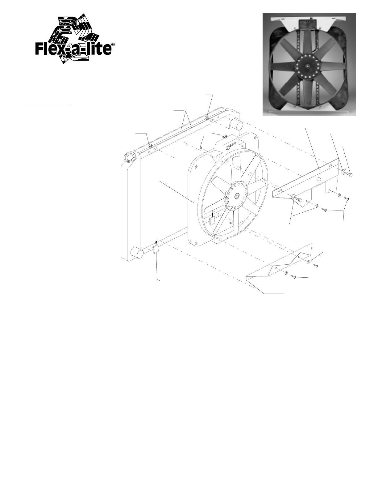
(1) fan, motor, & shroud assembly
(1) top aluminum bracket
(1) bottom aluminum bracket
(1) mounting kit bag
(1) electrical kit bag
(1) instruction sheet
Diagram A
Assembling the Fan
1. Using the screws, washers
and nuts in the mounting kit
bag, attach the large top
bracket to the top of the
electric fan shroud. See
diagram A
2. Again, using the screws,
washers and nuts provided,
attach the bottom aluminum
bracket to the bottom of the
electric fan shroud. See
diagram A.
3. Attach the thermostat control
knob provided in the electrical
kit bag to the thermostat in
the fan shroud.
Radiator
channel
Nut
Fan, motor &
shroud assembly
Radiator shroud
clip
Nut
Nut
Large top
bracket
Washer
Screw
Small bottom
bracket
Washer
Screw
Screw
Washer
Installation
1. Disconnect the battery.
2. Remove the vehicles original belt driven clutch & fan assembly. NOTE: It is not necessary to remove the
fan from the fan clutch.
3. Remove the vehicle’s factory fan shroud. Note: In some cases it may be easier to remove the fan, clutch
and shroud at once by simultaneously lifting each item upward.
4. Slide the small bottom bracket into the radiator shroud clips as the original shroud was mounted.
5. Tilt the electric fan assembly forward and match the bolt slots of the large top bracket to the bolt slots of
the radiator channel. Using the provided hardware, fasten the the unit securely. See Diagram A.
rev . 08-23-05 99978 p age 1 of 2
Page 2
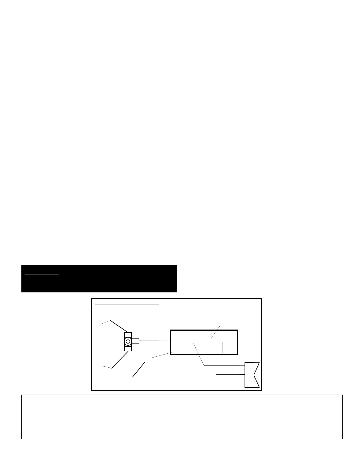
Wiring - Diagram C
Mandatory Connections
1. Connect the “+” terminal to a 12 volt positive (+) source. (i.e. fuse box)
Note: To stop the fan unit from operating when the vehicle is shut off, attach this wire to an ignition switched 12V power
source.
2. Connect the “B” terminal to a 12 volt positive (+) power source. (i.e. battery)
3 Connect the “G” terminal to ground. (i.e. chassis, negative(-) side of battery)
4. If you have air conditioning: with 3-way connector provided, pass the A/C clutch positive(+) wire (con-
nected to the A/C pump) through the connector. Place the black wire provided into the closed end of the
connector. Crimp metal plate. Snap plastic cover into place. Attach black wireto the "C" terminal of the
control box.
Insert probe in radiator core near upper hose. Install rubber cap over end of probe.
Adjusting the T emperature Control
1. Turn the adjustable control knob completely clockwise.
2. Idle the vehicle, when the vehicle is at 5 to 10 degrees higher than “normal” turn the adjustable control
knob counter clockwise until the fan comes on.
3. The fan will now activate at this temperature automatically and will shut off after it has cooled the vehicle
down 7 to 11 degrees. Note: It is typical for this fan unit to cycle on and off.
Optional Connection
(Note: Based on Flex-a-lite’s manual switch part # 31148, not included)
1. Connect the “M” terminal to terminal 1 on the switch.
2. Connect terminal 2 to a 12 volt positive(+) source.
3. Attach terminal 3 to ground to illuminate the switch.
Note (optional): T o stop the fan from activating thermost atically , omit the lead to the positive(+)
terminal of the control box. B, G, & M must remain connected.
*W ARNING: If not using Flex-a-lite's illuminated
switch (PN #31148) you must disconnect the switch
ground.
Mandatory Connections
+ 12 volt low amp
source
A/C Positive Lead
3-way
Connector
Optional Connection
G Ground
B 12 volt high amp
source
C Air conditioning relay
M Manual switch
Control Box
C
M
G
Ground
+
Diagram C
B
12 Volt Positive
The Flex-a-lite Limited Warranty
Flex-a-lite Consolidated, 7213-45th St. Ct. E. Fife, WA 98424, Telephone No. 253-922-2700, warrants to the original purchasing user, that all Flex-a-lite products to be free
of defects in material and workmanship for a period of 365 days (1 year) from date of purchase. Flex-a-lite products failing within 365 days (1 year) from date of purchase
may be returned to the factory through the point of purchase, transportation charges prepaid. If, on inspection, cause of failure is determined to be defective material or
workmanship and not by misuse, accidental or improper installation, Flex-a-lite will replace the fan free of charge, transportation prepaid. Flex-a-lite will not be liable for
incidental, progressive or consequential damages. Some states do not allow the exclusion or limitation of incidental or consequential damages, so the above limitation
or exclusion may not apply to you. This warranty gives you specific legal rights and you may have other rights, which vary from state to state.
The Flex-a-lite warranty is in compliance with the Magnuson-Moss Warranty Act of 1975.
In Line Fuse
12 Volt Source
Ground(Illuminate switch)
12 Volt Low Amp Source
1 2 3
rev . 08-23-05 99978 p age 2 of 2
 Loading...