

Page 1
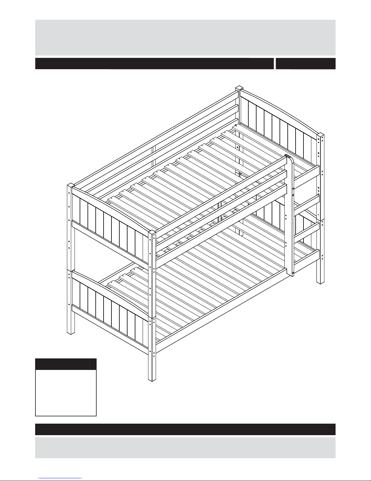
Classic antique bunkbed frame - 190x90 cm
Dimensions
Length - 195cm
Depth - 96/102cm
Height - 146cm
Weight - 43kg
Issue 3 - 03/09/15
Important – Please read these instructions fully before starting assembly
If you need help or have damaged or missing parts, call the Customer Helpline:
0045 7668 8055 or e-mail: order@fl exa.dk
Assembly Instructions - Please keep for future reference
6566878
Page 2

Safety and Care Advice
Important – Please read these instructions fully before starting assembly
• Check you have all the
components and tools listed on
pages 2, 3 and 4.
• Remove all fi ttings from the
plastic bags and separate them
into their groups.
• Keep children and animals
away from the work area, small
parts could choke if swallowed.
• Make sure you have enough
space to layout the parts before
starting.
• Do not stand or put weight on
the product, this could cause
damage.
• Assemble the item as close
to its fi nal position (in the same
room) as possible.
• Assemble on a soft level
surface to avoid damaging the
unit or your fl oor.
• Parts of the assembly will be
easier with 2 people.
• We do not
recommend the
use of power
drill/drivers for
inserting screws,
as this could
damage the unit. Only use hand
screwdrivers.
• Dispose of all packaging
carefully and responsibly.
• Only clean using a damp cloth
and mild detergent, do no use
bleach or abrasive cleaners.
• From time to time check that
there are no loose screws on
this unit.
• This product should not be
discarded with household waste.
Take to your local authority
waste disposal centre.
Care and maintenance
1
IMPORTANT - READ CAREFULLY -RETAIN FOR FUTURE REFERENCE
ASSEMBLY:
Always follow the instruction. Current legislation requires that the high bed / bunk bed must be fi tted with 4
safety-rails and a ladder or platform for the upper bunk. The high bed / bunk bed meets the European EN
747:2012 A1:2015 standards for security and durability.
MATTRESS:
This bed is designed to use a mattress size 190 cm long and 90 cm wide. The total thickness must not
exceed 16,1 cm. The mattress top must not pass the marking on the ladder / the post for the safety-rail.
WARNING:
High beds and the upper bed of bunk beds are not suitable for children under six years due to the risk of
injury from falls. Bunk beds and high beds can present a serious risk of injury from strangulation if not used
correctly. Never attach or hang items to any part of the bunk bed that are not designed to be used with the
bed, for example, but not limited to ropes, strings, cords, hooks, belts and bags. Children can be become
trapped between the bed and the wall, a roof pitch, the ceiling, adjoining pieces of furniture (e.g. cupboards)
and the like. To avoid risk of serious injury the distance between the top safety barrier and the adjoining
structure shall not exceed 75 mm or shall be more than 230 mm.
Do not use the high bed / bunk bed if any structural part is broken or missing.
MAINTENANCE INSTRUCTIONS:
Check regulary that all assembly fastenings are properly tightened. Ventilation of the room is necessary in
order to keep the humidity low and to prevent mould in and around the bed.
Page 3
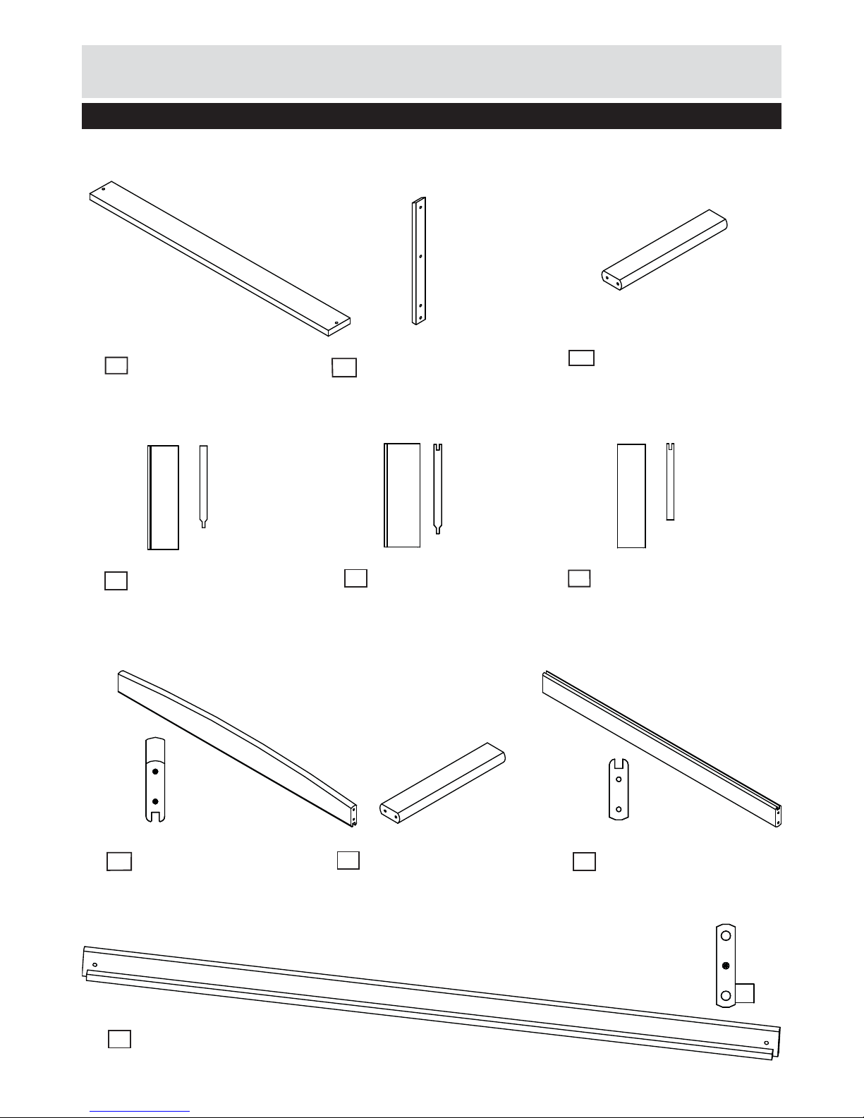
Components - Parts
Please check you have all the parts listed below
Panel x4 (27.6x8.7x0.8cm)
Panel x32 (27.6x9.4x0.8cm)
Tread (w.4 holes) x1
(35.0x6.5x2.0cm)
3
Panel x 4
(27.6x8.1x0.8cm)
6
Bedside x4
(186.7x8.9x2.0cm)
10
Slat x30
(89.7x6.5x1.5cm)
1
Endrail x4
(87.7x9.2x2.0cm)
7
Endrail x 4
(87.7x6.5x2.0cm)
4
5
9
List f.safety x2 (31.8x2.8x1.2cm)
2
No. 12-01203181-7
2
If you have damaged or missing components,
call the Customer Helpline: 0045 7668 8055
No. 12-02003503-7
No. 12-01508971
No. 12-00802761-7
No. 12-00802764-7
No. 12-00802765-7
No. 12-02008772-7
No. 12-02008771-7
No. 1305-18673-7
Tread (w.3 holes) x1
(35.0x6.5x2.0cm)
8
No. 12-02003504-7
Page 4
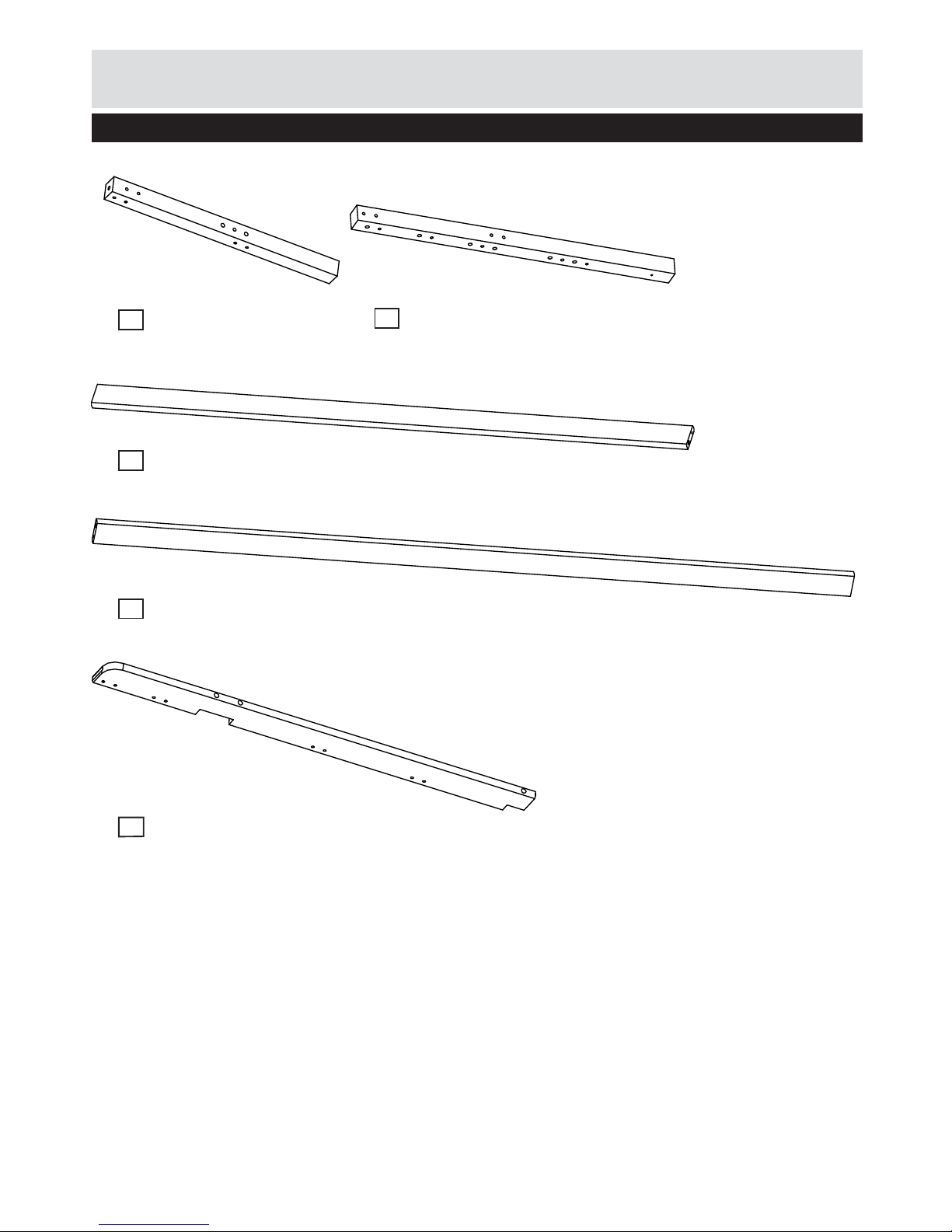
Components - Parts
Please check you have all the parts listed below
Leg short x4 (61.8x4.3x4.3cm)
11
No. 12-04306181-7
Safety rail 3/4 x2 (149.7x6.5x2.0cm)
12
No. 12-02014971-7
Leg long x4 (82.6x4.3x4.3cm)
13
No. 12-04308262-7
Safety rail 1/1 x2 (186.7x6.5x2.0cm)
14
No. 12-02018673-7
Ladderside bunkbed x1 (114.8x8.9x2.0cm)
15
No. 12-02011481-7
3
Page 5
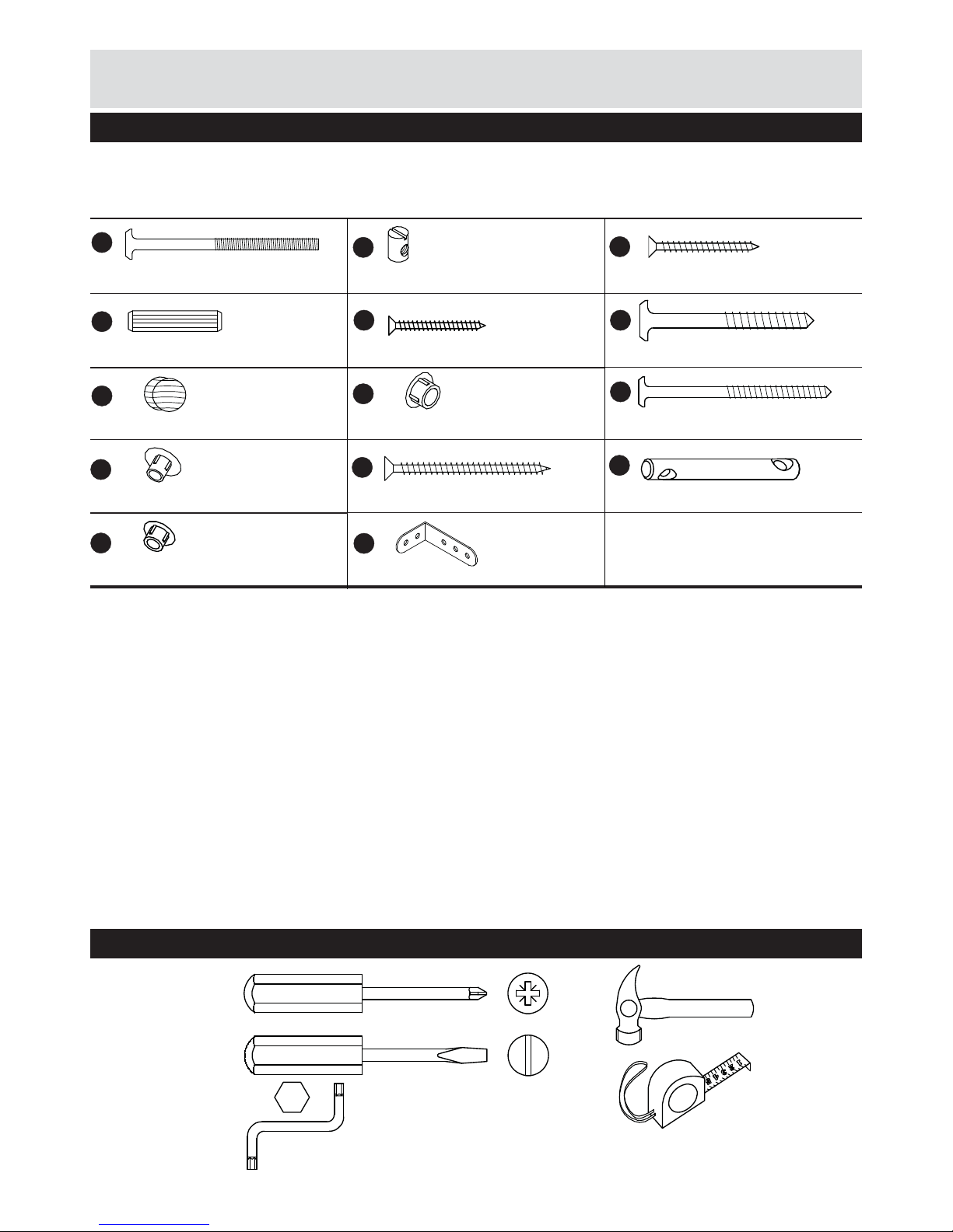
Please check you have all the fi ttings listed below
M6x90mm Connecting bolt x8
Tools required
A
Note: The quantities below are the correct amount to complete the assembly. In some cases more fi ttings
may be supplied than are required.
M6 Ø10x14mm Barrel nut x8
B
E
4,5x40mm Chipboard screw x4
C
10x45mm Dowel x22
D
Components - Fittings
Phillips
screwdriver
(medium)
Small
hammer
Ruler/tape
measure
4,0x30mm Chipboard screw x72
Allen key
4mm incl.
Flatblade
screwdriver
(medium)
6,3x50mm Assembly screw x8
F
No. 3909-63050
ø12x10mm Cover cap wood x3
G
No. 3939-00012-7
ø10mm Cover cap x10
H
No. 3938-00010-1
6,3x90mm Assembly screw x41
J
No. 3909-63090
ø7mm Cover cap x22
K
No. 3938-00007-1
4,5x60mm Chipboard screw x3
M
No. 3901-45060
ø10x88mm Connecting double bolt x4
N
No. 3934-10088
ø8mm Cover cap x8
L
No. 3938-000081-1
4
70x40,5x20mm Angle x2
O
No. 4008-022
No. 3901-45040
No. 3930-10045
No. 3901-40030
No. 3922-06014
No. 3913-06090
No. 4033-004
Page 6
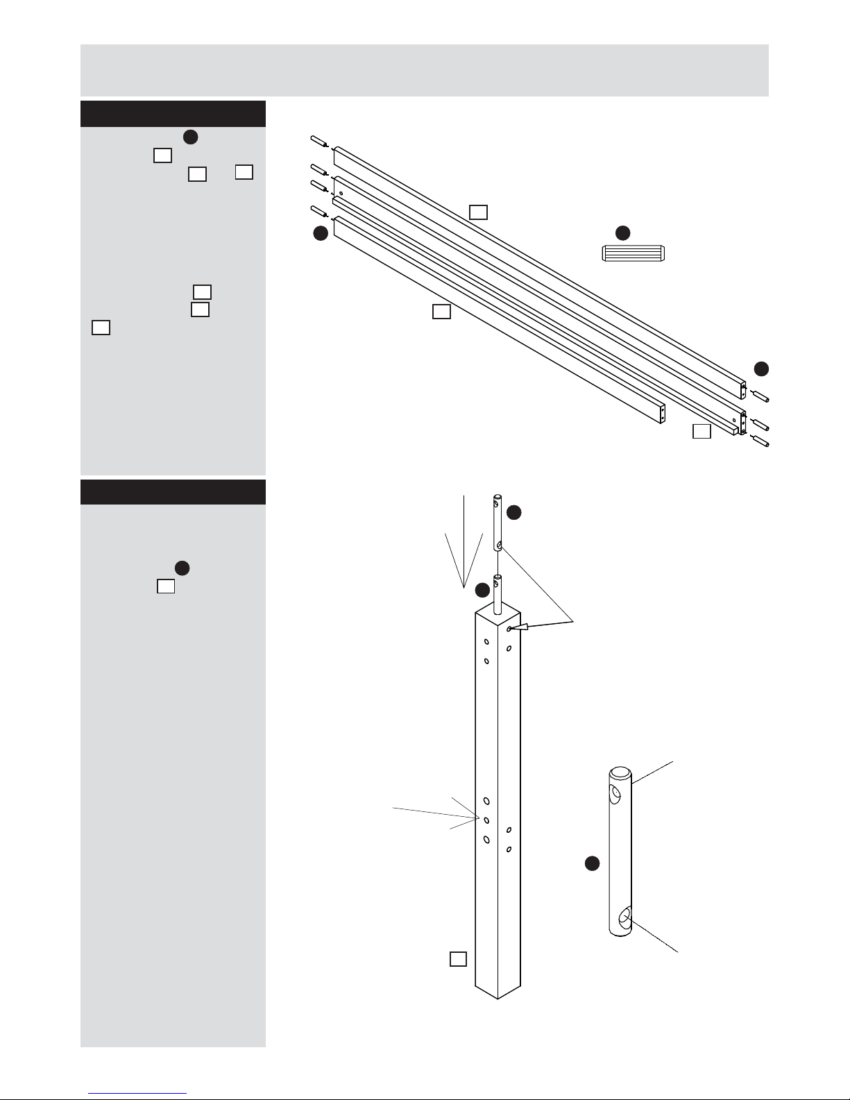
5
Assembly Instructions
Step 1
Step 2
Insert dowels to
bedsides – and to all
the safety rails and .
It may be necessary to
tap the dowel in very
gently with a small
hammer.
Repeat same procedure
for all bedsids
10
and
all safety rails
12
and
14
Insert the connecting
double bolts to all the
short legs
Twist /turn the bolt to
follow the hole ø6,8 mm
Counter sunk 5 mm
hole should face same
direction as bedside
drilling
11
11
10
10
12
14
D
N
D
N
12
14
D
N
D
x2
x2
x4
Ø5 MM
Ø6,8 MM
Ø6,8 MM
N
bedside
drilling
Page 7
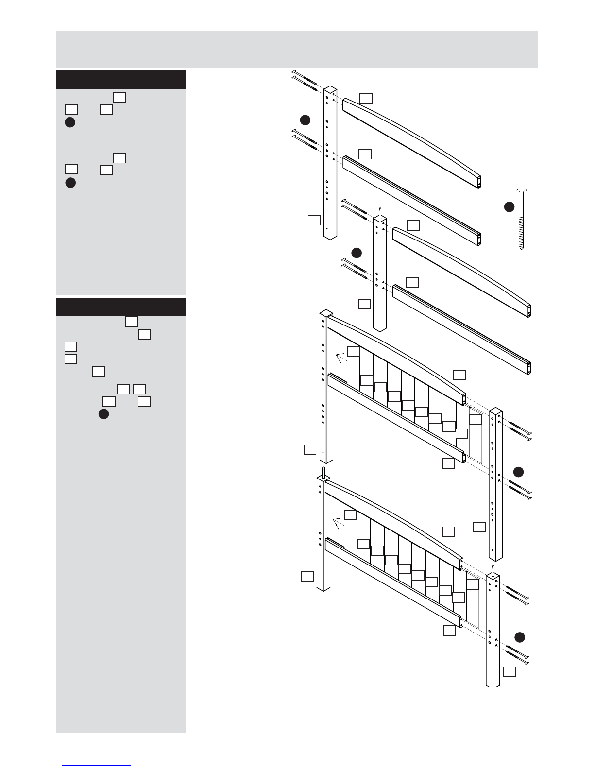
Important note:
A variation of the width of the panels of ±2-3%
has to be expected as wood is a live material,
i.e. variation of 2-3 cm per 1 meter.
Leaving some space at the panels, tongue & groove,
should be distributed regularly along the bed end.
If there is too little space for the panels, these should be
acclimatized for 2-5 days in order to adapt to the humidity
of the room.
The reason for this problem might be that the wood has absorbed a little
moisture during transportation/stocking.
Assembly Instructions
Step 3
Attach leg to endrails
. and with 4 screws
. using the allen key
Attach leg to endrails
. and with 4 screws
. using the allen key
Repeat same procedure
for both headboard and
footboard
Slide 1 panel
4
between endrail
7
and
9
followed by 8 panels
5
and fi nish with 1
panel
6
Attach legs
11/13
to
endrails
7
and 9 with
screws
J
using the allen
key.
Repeat same procedure
for both headboard and
footboard
Step 4
J
7
J
J
9
13
11
11
13
6
7
9
J
7
J
J
J
9
7
9
11
11
13
7
7
9
13
9
5
5
4
6
5
5
5
5
5
5
5
5
4
5
5
5
5
5
5
6
Page 8
F
Assembly Instructions
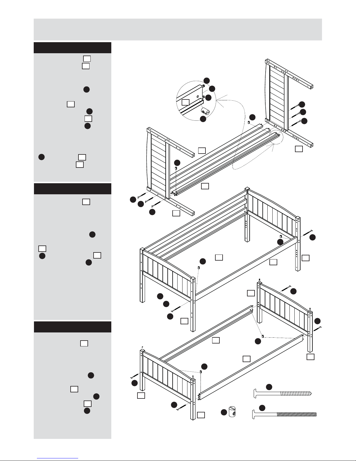
Step 5
Attach bedside and
both safety rails to the
bed fi rstly by placing the
dowels in holes in the legs.
Push barrel nuts into
the 2 small holes
in bedside push
1 connecting bolt
through each leg to
meet barrel nuts and
then fasten with the allen
key.
Push 4 assembly screws
. through legs to meet
the safety rails . and then
fasten with the allen key.
Attach bedside to
the bed fi rstly by
placing the dowels in
the holes in the legs.
Push 2 barrel nuts into
the small holes in bedside
. push 1 connecting bolt
. through each leg to
meet barrel nuts then
fasten with the allen key.
Attach bedside to the
bed fi rstly by placing the
dowels in the holes in the
leg.
Push 2 barrel nuts
into the small holes
in bedsides . push
one connecting bolt
through each leg to
meet barrel nuts and
then fasten with the allen
key.
Step 7
14
7
13
B
J
B
10
13
B
13
14
A
A
B
B
B
10
10
13
13
J
J
J
J
D
D
A
A
A
A
B
B
13
13
12
14
10
J
J
B
B
B
A
J
A
A
A
A
10
10
11
11
11
11
x2
x2
A
B
10
Step 6
10
A
10
B
10
11
B
10
Page 9
Assembly Instructions
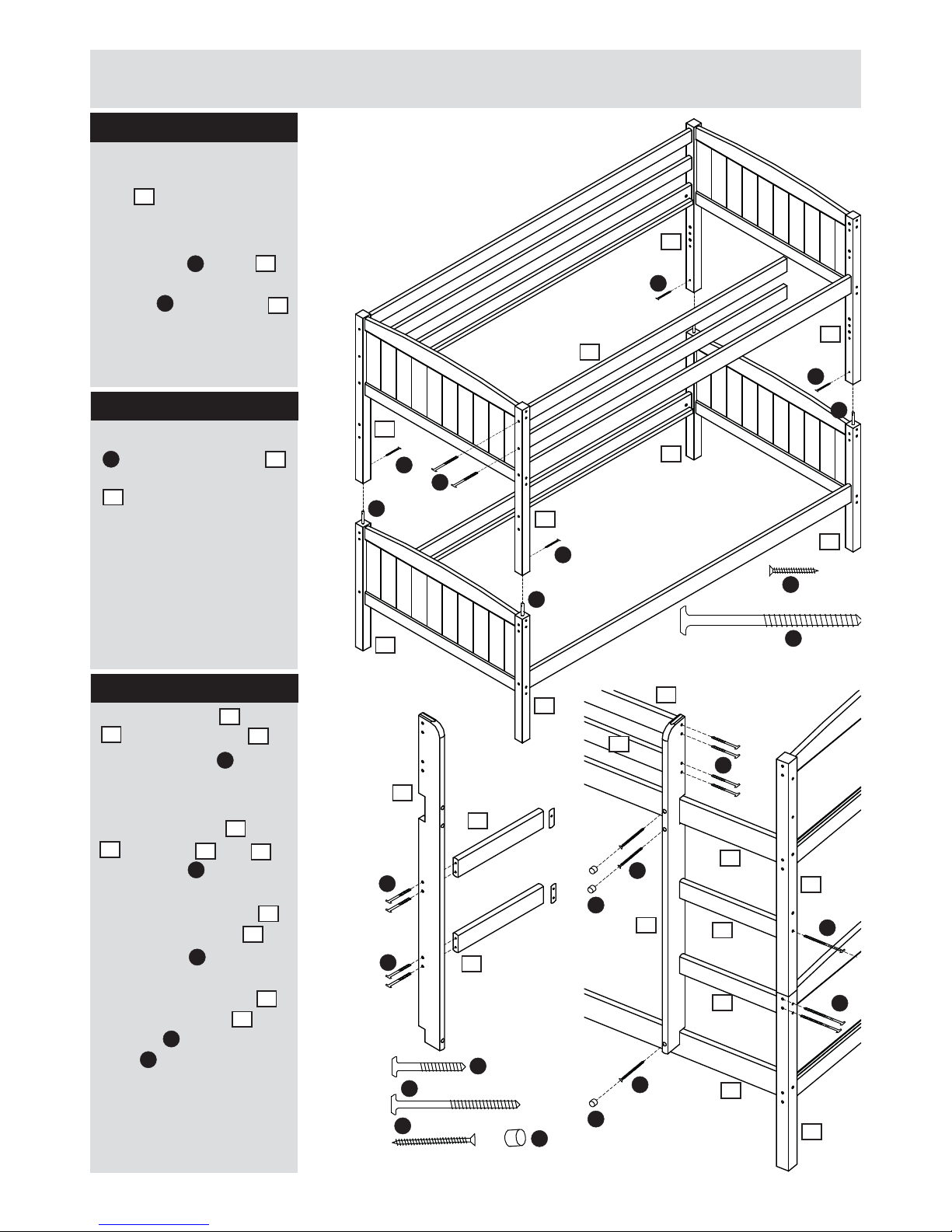
Step 8
Attach the 2 beds by
putting the one bed (with
legs ) in top of the
other bed.
Attach the connecting
double bolt in legs
with the upper bed by
screws through legs
Push 2 assembly screws
J
through the leg 13
to meet the safety rails
12
and then fasten
with the allen key.
Ladder can be
positioned
left or right !
Attach the tread and
. to the ladderside
with the screws
Attach the treads and
. to the leg and
with screws
Attach the ladderside
with the safety rails
with screws
Attach the ladderside
with the bedsides with
screws . Insert cover
caps in the holes.
Step 10
8
F
3
8
15
15
G
M
J
10
13
11
C
N
13
11
C
13
11
C
N
13
11
C
13
11
C
N
13
C
N
F
F
3
8
F
11
3
8
G
J
J
4 holes
3 holes
G
M
M
15
3
8
10
11
13
12
12
F
13
F
12
15
J
15
10
M
G
Step 9
J
J
12
x2
Page 10
9
Assembly Instructions
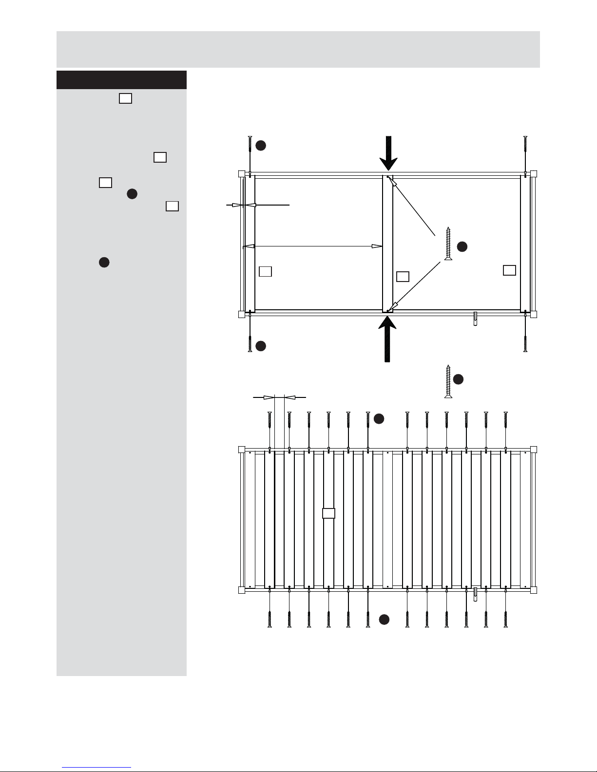
Step 11
Place 1 slat (No.8)
in the bed, follow the
measurement.
Push the bedsides .
together when attaching
the slat to the bed
with 2 screws Position
the remaining 14 slats
1
in the bed with a distance
of 64 mm between each.
Fasten each slat with 2 x
screws
1
E
64 mm
12 mm
1
10
E
912,5 mm
E
E
E
E
E
E
1
1
1
1
PUSH
PUSH
Page 11
Assembly Instructions
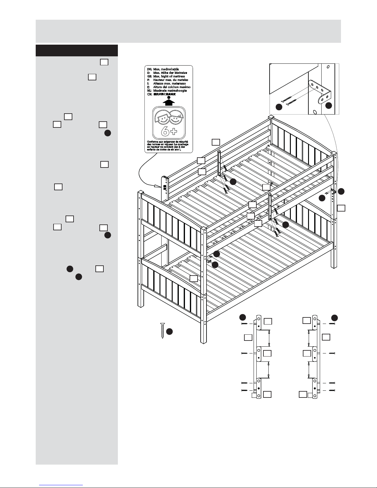
Step 12
Attach the safety list
inside the bed, on the
front safety rails
Should be in the center
of the front guards
between the slats.
Attach it to the safety
rails and bedside
with chipboard screws
Follow the measurement.
Attach the safety list
on the outside of the
bed, on the back safety
rails
14
should be in
the center of the back
guards.
Attach it to the safety
rails and bedside
with chipboard screws
Follow the measurement.
Attach wall mounting
brackets
O
to legs 11
with screws
E
.
Max. mattress height !
Assembly is complete.
2
12
2
12
10
E
2
2
14
10
E
10
Max mattress height !
2
2
2
2
E
E
E
E
E
8 8
8
10
12
12
12
12
71 mm
71 mm
10
10
10
E
E
E
O
O
O
11
11
Page 12
If you need help or have damaged or missing parts,
call the Customer Helpline: 0045 7668 8055
E-mail: order@fl exa.dk
Ref.no. 44-01115-7 C Stand: 030915 Page 12 (80-10403-7)
11
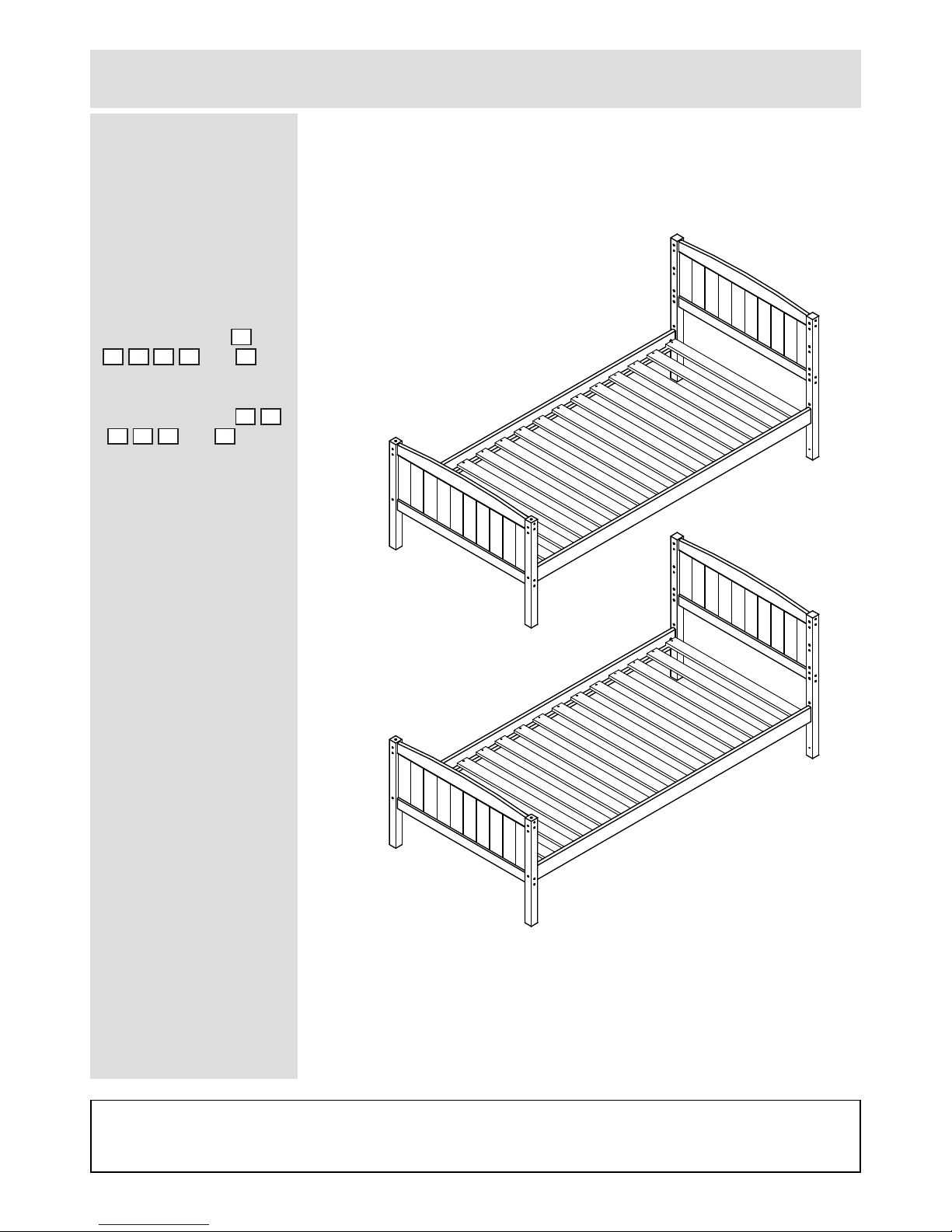
Assembly Instructions
Note: To acheive the
single bed look shown
on the picture, one
end of the upper bunk
(assembled parts
4
,
5,6,7,9
and )
should be swapped
over with the lower bunk
(assembled parts
4,5
,6,7,9 and 11).
Bunkbed as 2 single beds
13
 Loading...