

Page 1

User Guide
ROA 128 5068
POL SIP Evaluation Board
1/28701-ROA 128 5068 Rev A May 2018
© Flex
POL SIP Evaluation Board
ROA 128 5068
User Guide
Page 2

User Guide
2
ROA 128 5068
POL SIP Evaluation Board
1/28701-ROA 128 5068 Rev A May 2018
© Flex
Contents
1 User Guide ........................................................................................ 3
1.1 Power Up/Down Instructions ............................................................. 3
1.1.1 Power Supply Connection ................................................................. 3
1.2 USB to PMBus connections ............................................................... 4
1.3 Board to board connectors ................................................................ 6
2 Address and vout range resistors ...................................................... 7
2.1 Change of address resistors .............................................................. 8
2.1.1 BMR 462 adjustment of address resistors ......................................... 8
2.1.2 BMR 463/464 adjustment of address resistors .................................. 9
2.2 Change of Vout range resistors ....................................................... 10
2.2.1 BMR 462 adjustment of vout range resistors ................................... 10
2.2.2 BMR 463/464 adjustment of vout range resistors ............................ 11
3 Modification for Parallel Operation ................................................... 12
4 Dimensions ..................................................................................... 13
Page 3

User Guide
3
ROA 128 5068
POL SIP Evaluation Board
1/28701-ROA 128 5068 Rev A May 2018
© Flex
1 User Guide
1.1 Power Up/Down Instructions
This section of the document describes how to connect power supply for
different cases in order to avoid mistake during measurements.
1.1.1 Power Supply Connection
Connect 5-14V DC power to the “+IN and “-IN”” connectors (see Fig 1.1).
Fig 1.1 Connect 5-14V to either of the “+IN”and “-IN” DC power connectors located in
both ends of the board (see blue rectangles).
Fig 1.2 shows the RC switch in “On” position.
Fig 1.2 the RC switch in “On” position.
SW1
Page 4
User Guide
4
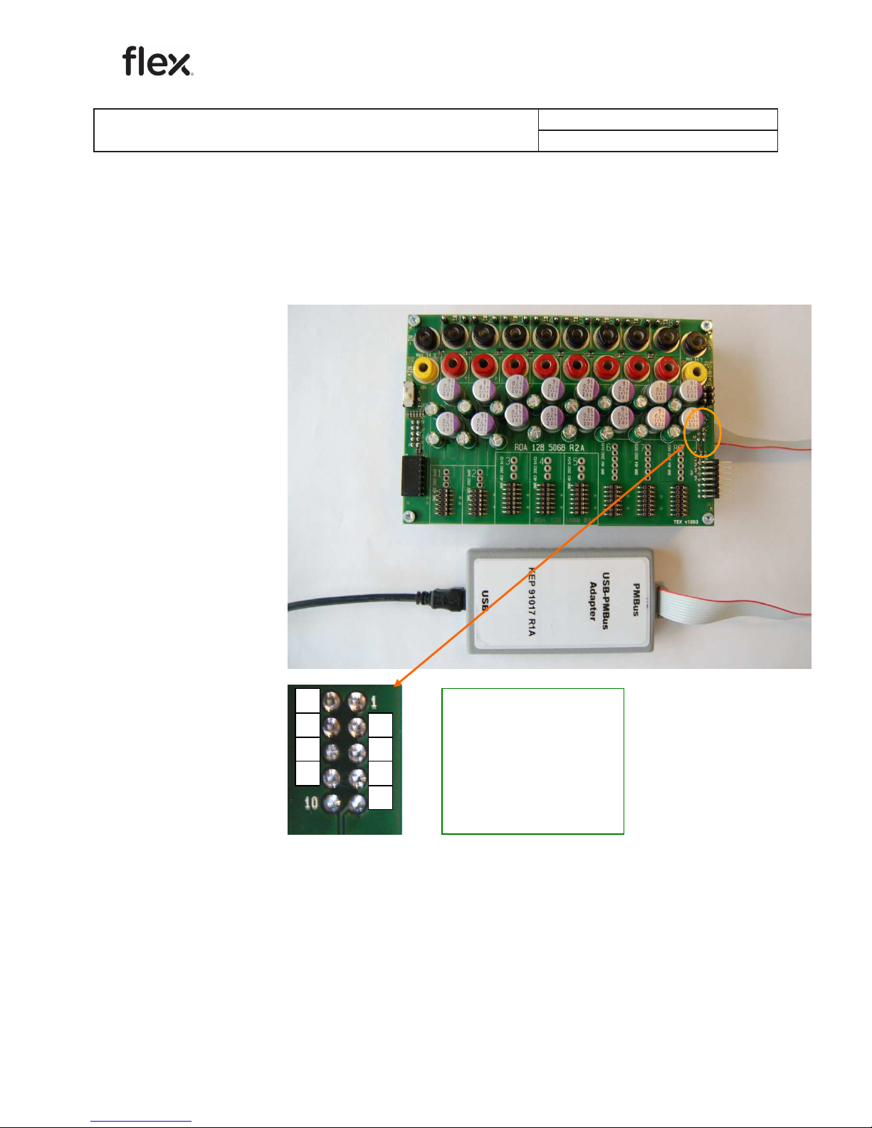
1 NC
3 NC
5 VI2C
7 CTRL
9 SCL
2 NC
4 NC
6 DGND
8 SALERT
10 SDA
ROA 128 5068
POL SIP Evaluation Board
1/28701-ROA 128 5068 Rev A May 2018
© Flex
1.2 USB to PMBus connections
Fig 1.3a and Fig 1.3b shows the connection of two types of USB-to-PMBus
adapters.
Fig 1.3a Connection of the Flex KEP 910 17 PMBus-to-USB adapter
(connector is found on the back side of the ROA 128 5068 board)
2
4
6
8
3
5
7
9
Page 5

User Guide
5
10 SDA
8 DGND
6 SALERT
4 VI2C
2 SCL
9 NC
7 NC
5 NC
3 NC
1 NC
ROA 128 5068
POL SIP Evaluation Board
1/28701-ROA 128 5068 Rev A May 2018
© Flex
Fig 1.3b Connection of the Intersil ZLUSBREF02 PMBus-to-USB adapter
(connector is found on the back side of the ROA 128 5068 board)
1.2.1 Power-up instruction:
- Mount the BMR:s in the desired positions
- Connect and turn On the 5-14 V supply
- Turn RC switch in On position
▪
The LEDs should now give green light, (unless the
outputs of the BMRs are not configured to be disabled).
- Connect the PMBus Adapter/Cable to the board.
- Start the software program.
1.2.2 Power-down instruction:
- Turn RC switch in Off position or turn Off the 5-14V Supply
- Now, the BMR modules can be removed/replaced.
9
7
5
3
8
6
4
2
Page 6

User Guide
6
ROA 128 5068
POL SIP Evaluation Board
1/28701-ROA 128 5068 Rev A May 2018
© Flex
1.3 Board to board connectors
Fig 1.4 shows the board to board connectors
The following signals are connected to the board to board connectors:
SYNC
SALERT
SCL
SDA
CTRL
GND
This board can be connected to other 3E evaluation boards through the board
to board connectors. All interconnected boards are sharing the same PMBus
and SYNC signals and only one PMBus to USB adapter is needed.
Note: When the switch SW1 (see fig 1.2) is in On position the CTRL_ALL pin
on each module is connected to CTRL which is connected to the board to
board connectors.
PMBus I/O
connector
Board I/O
connector
Fig 1.4 Board to board connectors
Page 7

User Guide
7
ROA 128 5068
POL SIP Evaluation Board
1/28701-ROA 128 5068 Rev A May 2018
© Flex
2 Address and vout range resistors
This section describes the locations of the Address and Vout-range pinstrap
resistors, see table 1 for the resistors for each POL position. To know what
resistor value to mount, please look in the actual technical specification of the
BMR product.
Fig 2.1 shows the positions of the address and vout range resistors.
Fig 2.1 Positions of the address and vout range resistors.
Page 8

User Guide
8
ROA 128 5068
POL SIP Evaluation Board
1/28701-ROA 128 5068 Rev A May 2018
© Flex
2.1 Change of address resistors
2.1.1 BMR 462 adjustment of address resistors
To change the address in a position, change the resistors values as shown in
fig. 2.2.
Fig 2.2 Address resistors in positions for BMR 462.
Page 9

User Guide
9
ROA 128 5068
POL SIP Evaluation Board
1/28701-ROA 128 5068 Rev A May 2018
© Flex
2.1.2 BMR 463/464 adjustment of address resistors
To change the address in a position, change the resistors values as shown in
fig. 2.3.
Fig 2.3 Address resistors in positions for BMR 463/464.
RSA1 RSA0
Page 10

User Guide
10
ROA 128 5068
POL SIP Evaluation Board
1/28701-ROA 128 5068 Rev A May 2018
© Flex
2.2 Change of Vout range resistors
2.2.1 BMR 462 adjustment of vout range resistors
To change the vout range in a position, change the resistors values as shown
in fig. 2.4.
Fig 2.4 Vout range resistors in positions for BMR 462.
Page 11

User Guide
11
ROA 128 5068
POL SIP Evaluation Board
1/28701-ROA 128 5068 Rev A May 2018
© Flex
2.2.2 BMR 463/464 adjustment of vout range resistors
To change the vout range in a position, change the resistors values as shown
in fig. 2.5.
Fig 2.5 Vout range resistors in positions for BMR 463/464.
POL position / Address Address resistors RSA0 / RSA1 Vout range resistor
1 / 0x6B
R103
R104
2 / 0x6C
R203
R204
3 / 0x52
R303 / R304
R305
4 / 0x53
R403 / R404
R405
5 / 0x54
R503 / R504
R505
6 / 0x55
R603 / R604
R605
7 / 0x56
R703 / R704
R705
8 / 0x57
R803 / R804
R805
Table 1 Address resistors and Vout resistors for different POL positions.
Page 12

User Guide
12
ROA 128 5068
POL SIP Evaluation Board
1/28701-ROA 128 5068 Rev A May 2018
© Flex
3 Modification for Parallel Operation
It is possible to operate two or three BMR 463 2002 or two or three BMR 464
2002 in parallel by connecting the output voltage connectors together.
For proper performance the connection shall be of low impedance and the
point of connection shall be at the PCB as indicated in Figure 3.1.
As connection power jumpers can be used as shown in Figure 3.2. Note that
the power jumpers shall be attached below the ring nuts of the output voltage
connectors. Alternatively the connection can be made of a piece of thick
copper wire that is soldered directly to the PCB.
Fig 3.1. Connection of output voltage for parallel operation.
Fig 3.2. Connection with power jumpers.
BMR 464
BMR 463
Points of connection
Page 13

User Guide
13
ROA 128 5068
POL SIP Evaluation Board
1/28701-ROA 128 5068 Rev A May 2018
© Flex
4 Dimensions
The outer dimensions (in mm) of the test board are shown in Fig 4.1.
Fig 4.1 The outer dimensions (in mm).
The whole test board has the outer dimensions 140 x 95 x 39.1 mm (L x W x
H). Weight of the complete test board is ~220 g.
 Loading...