

Page 1
L 3709-115
L 3709-125
LE 9-10 125
L 10-10 125
L 801
L 1001
Page 2

Originalbetriebsanleitung . . . . . . . . . . . . . . . . . . . . . . . 3
Original operating instructions . . . . . . . . . . . . . . . . . . . 14
Notice d’instructions d’origine . . . . . . . . . . . . . . . . . . . 24
Istruzioni per l’uso originali . . . . . . . . . . . . . . . . . . . . . . 35
Instrucciones de funcionamiento originales . . . . . . . . . 46
Instruções de serviço originais . . . . . . . . . . . . . . . . . . . 57
Originele gebruiksaanwijzing . . . . . . . . . . . . . . . . . . . . 68
Originale driftsvejledning . . . . . . . . . . . . . . . . . . . . . . . 79
Originale driftsanvisningen . . . . . . . . . . . . . . . . . . . . . . 89
Originalbruksanvisning . . . . . . . . . . . . . . . . . . . . . . . . . 99
Alkuperäinen käyttöohjekirja . . . . . . . . . . . . . . . . . . . . 109
Αυθεντικές οδηγίες χειρισμού . . . . . . . . . . . . . . . . . . . . . 119
Orijinal işletme kılavuzu . . . . . . . . . . . . . . . . . . . . . . . . . . 130
Instrukcja oryginalna . . . . . . . . . . . . . . . . . . . . . . . . . . . . 140
Eredeti üzemeltetési útmutató . . . . . . . . . . . . . . . . . . . 151
Originální návod k obsluze . . . . . . . . . . . . . . . . . . . . . . 162
Originálny návod na obsluhu . . . . . . . . . . . . . . . . . . . . 172
Originalna uputa za rad . . . . . . . . . . . . . . . . . . . . . . . . 183
Izvirno navodilo za obratovanje . . . . . . . . . . . . . . . . . . 193
Instrucţiuni de funcţionare originale . . . . . . . . . . . . . . . 203
Оригинално упътване за експлоатация . . . . . . . . . . 214
Оригинальная инструкция по эксплуатации
Originaalkasutusjuhend . . . . . . . . . . . . . . . . . . . . . . . . 237
Originali naudojimo instrukcija . . . . . . . . . . . . . . . . . . . 247
Lietošanas pamācības oriģināls . . . . . . . . . . . . . . . . . . 257
. . . . . . . . . . . . . . . . . . . . . . . . . . . . . . 278
. . . . . .
225
Page 3
L 3709 -115, L 3709 -125, LE 9-10 125, L 10-10 125, L 801, L 1001
Inhalt
Verwendete Symbole . . . . . . . . . . . . . . . 3
Symbole am Gerät . . . . . . . . . . . . . . . . . 3
Technische Daten . . . . . . . . . . . . . . . . . . 8
Auf einen Blick . . . . . . . . . . . . . . . . . . . . 9
Zu Ihrer Sicherheit . . . . . . . . . . . . . . . . . 10
Geräusch und Vibration . . . . . . . . . . . . . 7
Gebrauchsanweisung . . . . . . . . . . . . . . 10
Wartung und Pflege . . . . . . . . . . . . . . . 12
Entsorgungshinweise . . . . . . . . . . . . . . 13
-Konformität. . . . . . . . . . . . . . . . . . . . 13
Haftungsausschluss . . . . . . . . . . . . . . . 13
Verwendete Symbole
WARNUNG!
Bezeichnet eine unmittelbar drohende
Gefahr. Bei Nichtbeachten des Hinweises
drohen Tod oder schwerste Verletzungen.
VORSICHT!
Bezeichnet eine möglicherweise
gefährliche Situation. Bei Nichtbeachten
des Hinweises drohen Verletzungen oder
Sachschäden.
HINWEIS
Bezeichnet Anwendungstips und wichtige
Informationen.
Symbole am Gerät
Vor Inbetriebnahme
Bedienungsanleitung lesen!
Augenschutz tragen!
Schutzklasse II (vollständig
isoliert)
Entsorgungshinweis für das
Altgerät (siehe Seite 13)!
Zu Ihrer Sicherheit
WARNUNG!
Vor Gebrauch des Winkelschleifers lesen
und danach handeln:
–
die vorliegende Bedienungsanleitung,
–
die „Allgemeinen Sicherheitshinweise“
zum Umgang mit Elektrowerkzeugen im
beigelegten Heft (Schriften-Nr.:
315.915),
–
die für den Einsatzort geltenden Regeln
und Vorschriften zur Unfallverhütung.
Dieser Winkelschleifer ist nach dem Stand
der Technik und den anerkannten
sicherheits technischen Regeln gebaut.
Dennoch können bei seinem Gebrauch
Gefahren für Leib und Leben des Benutzers
oder Dritter bzw. Schäden an der Maschine
oder an anderen Sachwerten entstehen.
Der Winkelschleifer ist nur zu benutzen
–
für die bestimmungsgemäße
Verwendung,
–
in sicherheitstechnisch einwandfreiem
Zustand.
Die Sicherheit beeinträchtigende Störungen
umgehend beseitigen.
Bestimmungsgemäße Verwendung
Dieser Winkelschleifer ist bestimmt
– für den gewerblichen Einsatz in Industrie
und Handwerk,
– zum Schleifen und Trennen von Metall
und Stein im Trockenschliff; zum
Trennen ist eine spezielle
Trennschutzhaube erforderlich,
– zum Einsatz mit Schleifwerkzeug und
Zubehör, das in dieser Anleitung
angegeben oder vom Hersteller
empfohlen wird und für eine
Umfangsgeschwindigkeit von 80 m/s
zugelassen ist.
Nicht zulässig sind z. B. Kettenfrässcheiben,
Sägeblätter.
3
Page 4

L 3709 -115, L 3709 -125, LE 9-10 125, L 10-10 125, L 801, L 1001
Sicherheitshinweise für
Winkelschleifer
WARNUNG!
Lesen Sie alle mit dem Elektrowerkzeug
gelieferten Sicherheitshinweise, Anweisungen, Abbildungen und Spezifikationen.
Fehler bei der Einhaltung der folgenden
Warnhinweise können elektrischen Schlag,
Brand und/oder schwere Verletzungen
verursachen. Bewahren Sie alle Sicherheitshinweise und Anweisungen für die
Zukunft auf.
Gemeinsame Sicherheitshinweise zum
Schleifen und Trennschleifen:
Dieses Elektrowerkzeug ist zu verwenden
als Schleifer und Trennschleifmaschine.
Beachten Sie alle Sicherheitshinweise,
Anweisungen, Darstellungen und Daten,
die Sie mit dem Gerät erhalten.
Wenn Sie die folgenden Anweisungen
nicht beachten. kann es zu elektrischem
Schlag, Feuer und/oder schweren
Verletzungen kommen.
Dieses Elektrowerkzeug ist nicht geeignet
zum Sandpapierschleifen, Arbeiten mit
Drahtbürsten und Polieren.
Verwendungen, für die das
Elektrowerkzeug nicht vorgesehen ist,
können Gefährdungen und Verletzungen
verursachen.
Verwenden Sie kein Zubehör, das vom
Hersteller nicht speziell für dieses
Elektrowerkzeug vorgesehen und
empfohlen wurde.
Nur weil Sie das Zubehör an Ihrem
Elektrowerkzeug befestigen können,
garantiert das keine sichere
Verwendung.
Die zulässige Drehzahl des
Einsatzwerkzeugs muss mindestens so
hoch sein wie die auf dem
Elektrowerkzeug angegebene
Höchstdrehzahl.
schneller als zulässig dreht, kann
zerbrechen und umherfliegen.
Zubehör, das sich
Außendurchmesser und Dicke des
Einsatzwerkzeugs müssen den
Maßangaben Ihres Elektrowerkzeugs
entsprechen.
Falsch bemessene Einsatzwerkzeuge
können nicht ausreichend abgeschirmt
oder kontrolliert werden.
Schleifscheiben, Schleifteller oder
anderes Zubehör müssen genau auf die
Schleifspindel Ihres Elektrowerkzeugs
passen.
Einsatzwerkzeuge, die nicht genau auf
die Schleifspindel des Elektrowerkzeugs
passen, drehen sich ungleichmäßig,
vibrieren sehr stark und können zum
Verlust der Kontrolle führen.
Verwenden Sie keine beschädigten
Einsatzwerkzeuge. Kontrollieren Sie vor
jeder Verwendung Einsatzwerkzeuge auf
Absplitterungen und Risse, Schleifteller
auf Risse, Verschleiß oder starke
Abnutzung. Wenn das Elektrowerkzeug
oder das Einsatzwerkzeug herunterfällt,
überprüfen Sie, ob es beschädigt ist, oder
verwenden Sie ein unbeschädigtes
Einsatzwerkzeug. Wenn Sie das
Einsatzwerkzeug kontrolliert und
eingesetzt haben, halten Sie und in der
Nähe befindliche Personen sich
außerhalb der Ebene des rotierenden
Einsatzwerkzeugs auf und lassen Sie das
Gerät eine Minute lang mit
Höchstdrehzahl laufen.
Beschädigte Einsatzwerkzeuge brechen
meist in dieser Testzeit.
Tragen Sie persönliche
Schutzausrüstung. Verwenden Sie je
nach Anwendung Vollgesichtsschutz,
Augenschutz oder Schutzbrille. Soweit
angemessen, tragen Sie Staubmaske,
Gehörschutz, Schutzhandschuhe oder
Spezialschürze, die kleine Schleif
-
Materialpartikel von Ihnen fernhält.
Augen sollen vor herumfliegenden
Fremdkörpern geschützt werden, die bei
verschiedenen Anwendungen entstehen.
Staub
-
oder Atemschutzmaske müssen
den bei der Anwendung entstehenden
Staub filtern. Wenn Sie lange lautem Lärm
ausgesetzt sind, können Sie einen
Hörverlust erleiden.
und
Die
4
Page 5

L 3709 -115, L 3709 -125, LE 9-10 125, L 10-10 125, L 801, L 1001
Achten Sie bei anderen Personen auf
sicheren Abstand zu Ihrem
Arbeitsbereich. Jeder, der den
Arbeitsbereich betritt, muss persönliche
Schutzausrüstung tragen.
Bruchstücke des Werkstücks oder
gebrochener Einsatzwerkzeuge können
wegfliegen und Verletzungen auch
außerhalb des direkten Arbeitsbereichs
verursachen.
Halten Sie das Gerät nur an den isolierten
Griffflächen, wenn Sie Arbeiten ausführen,
bei denen das Einsatzwerkzeug
verborgene Stromleitungen oder das
eigene Netzkabel treffen kann.
Der Kontakt mit einer
spannungsführenden Leitung kann auch
metallene Geräteteile unter Spannung
setzen und zu einem elektrischen Schlag
führen.
Halten Sie das Netzkabel von sich
drehenden Einsatzwerkzeugen fern.
Wenn Sie die Kontrolle über das Gerät
verlieren, kann das Netzkabel
durchtrennt oder erfasst werden und Ihre
Hand oder ihr Arm in das sich drehende
Einsatzwerkzeug geraten.
Legen Sie das Elektrowerkzeug niemals
ab, bevor das Einsatzwerkzeug völlig zum
Stillstand gekommen ist.
Das sich drehende Einsatzwerkzeug
kann in Kontakt mit der Ablagefläche
geraten, wodurch Sie die Kontrolle über
das Elektrowerkzeug verlieren können.
Lassen Sie das Elektrowerkzeug nicht
laufen, während Sie es tragen.
Ihre Kleidung kann durch zufälligen
Kontakt mit dem sich drehenden
Einsatzwerkzeug erfasst werden und das
Einsatzwerkzeug sich in Ihren Körper
bohren.
Reinigen Sie regelmäßig die
Lüftungsschlitze Ihres Elektrowerkzeugs.
Das Motorgebläse zieht Staub in das
Gehäuse, und eine starke Ansammlung
von Metallstaub kann elektrische
Gefahren verursachen.
Verwenden Sie das Elektrowerkzeug nicht
Verwenden Sie keine Einsatzwerkzeuge,
die flüssige Kühlmittel erfordern.
Die Verwendung von Wasser oder
anderen flüssigen Kühlmitteln kann zu
einem elektrischen Schlag führen.
Rückschlag und entsprechende
Sicherheitshinweise
Rückschlag ist die plötzliche Reaktion infolge
eines hakenden oder blockierten drehenden
Einsatzwerkzeugs, wie Schleifscheibe,
Schleifteller, Drahtbürste usw. Verhaken oder
Blockieren führt zu einem abrupten Stopp des
rotierenden Einsatzwerkzeugs. Dadurch wird
ein unkontrolliertes Elektrowerkzeug gegen
die Drehrichtung des Einsatzwerkzeugs an
der Blockierstelle beschleunigt.
Wenn z. B. eine Schleifscheibe im Werkstück
hakt oder blockiert, kann sich die Kante der
Schleifscheibe, die in das Werkstück
eintaucht, verfangen und dadurch die
Schleifscheibe ausbrechen oder einen
Rückschlag verursachen. Die Schleifscheibe
bewegt sich dann auf die Bedienperson zu
oder von ihr weg, je nach Drehrichtung der
Scheibe an der Blockierstelle. Hierbei können
Schleifscheiben auch brechen.
Ein Rückschlag ist die Folge eines falschen
oder fehlerhaften Gebrauchs des
Elektrowerkzeugs. Er kann durch geeignete
Vorsichtsmaßnahmen, wie nachfolgend
beschrieben, verhindert werden.
Halten Sie das Elektrowerkzeug gut fest
und bringen Sie Ihren Körper und Ihre
Arme in eine Position, in der Sie die
Rückschlagkräfte abfangen können.
Verwenden Sie immer den Zusatzgriff,
falls vorhanden, um die größtmögliche
Kontrolle über Rückschlagkräfte oder
Reaktionsmomente beim Hochlauf zu
haben.
Die Bedienperson kann durch geeignete
Vorsichtsmaßnahmen die Rückschlagund Reaktionskräfte beherrschen.
Bringen Sie Ihre Hand nie in die Nähe sich
drehender Einsatzwerkzeuge.
Das Einsatzwerkzeug kann sich beim
Rückschlag über Ihre Hand bewegen.
in der Nähe brennbarer Materialien.
Funken können diese Materialien
entzünden.
5
Page 6

L 3709 -115, L 3709 -125, LE 9-10 125, L 10-10 125, L 801, L 1001
Meiden Sie mit Ihrem Körper den Bereich,
in den das Elektrowerkzeug bei einem
Rückschlag bewegt wird.
Der Rückschlag treibt das
Elektrowerkzeug in die Richtung
entgegengesetzt zur Bewegung der
Schleifscheibe an der Blockierstelle.
Arbeiten Sie besonders vorsichtig im
Bereich von Ecken, scharfen Kanten usw.
Verhindern Sie, dass Einsatzwerkzeuge
vom Werkstück zurückprallen und
verklemmen.
Das rotierende Einsatzwerkzeug neigt
bei Ecken, scharfen Kanten oder wenn
es abprallt dazu, sich zu verklemmen.
Dies verursacht einen Kontrollverlust
oder Rückschlag.
Verwenden Sie kein Ketten- oder
gezähntes Sägeblatt.
Solche Einsatzwerkzeuge verursachen
häufig einen Rückschlag oder den
Verlust der Kontrolle über das
Elektrowerkzeug.
Besondere Sicherheitshinweise zum
Schleifen und Trennschleifen:
Verwenden Sie ausschließlich die für Ihr
Elektrowerkzeug zugelassenen
Schleifkörper und die für diese
Schleifkörper vorgesehene Schutzhaube.
Schleifkörper, die nicht für das
Elektrowerkzeug vorgesehen sind,
können nicht ausreichend abgeschirmt
werden und sind unsicher.
Die Schutzhaube muss sicher am
Elektrowerkzeug angebracht und so
eingestellt sein, dass ein Höchstmaß an
Sicherheit erreicht wird, d. h. der
kleinstmögliche Teil des Schleifkörpers
zeigt offen zur Bedienperson.
Die Schutzhaube soll die Bedienperson
vor Bruchstücken und zufälligem Kontakt
mit dem Schleifkörper schützen.
Schleifkörper dürfen nur für die
empfohlenen Einsatzmöglichkeiten
verwendet werden. Zum Beispiel:
Schleifen Sie nie mit der Seitenfläche
einer Trennscheibe.
Trennscheiben sind zum Materialabtrag
mit der Kante der Scheibe bestimmt.
Seitliche Krafteinwirkung auf diese
Schleifkörper kann sie zerbrechen.
Verwenden Sie immer unbeschädigte
Spannflansche in der richtigen Größe und
Form für die von Ihnen gewählte
Schleifscheibe.
Geeignete Flansche stützen die
Schleifscheibe und verringern so die
Gefahr eines Schleifscheibenbruchs.
Flansche für Trennscheiben können sich
von den Flanschen für andere
Schleifscheiben unterscheiden.
Verwenden Sie keine abgenutzten
Schleifscheiben von größeren
Elektrowerkzeugen.
Schleifscheiben für größere
Elektrowerkzeuge sind nicht für die
höheren Drehzahlen von kleineren
Elektrowerkzeugen ausgelegt und
können brechen.
Besondere Sicherheitshinweise zum
Trennschleifen:
Vermeiden Sie ein Blockieren der
Trennscheibe oder zu hohen
Anpressdruck. Führen Sie keine
übermäßig tiefen Schnitte aus.
Eine Überlastung der Trennscheibe
erhöht deren Beanspruchung und die
Anfälligkeit zum Verkanten oder
Blockieren und damit die Möglichkeit
eines Rückschlags oder
Schleifkörperbruchs.
Meiden Sie den Bereich vor und hinter der
rotierenden Trennscheibe.
Wenn Sie die Trennscheibe im
Werkstück von sich wegbewegen, kann
im Falle eines Rückschlags das
Elektrowerkzeug mit der sich drehenden
Scheibe direkt auf Sie zugeschleudert
werden.
Falls die Trennscheibe verklemmt oder
Sie die Arbeit unterbrechen, schalten Sie
das Gerät aus und halten Sie es ruhig, bis
die Scheibe zum Stillstand gekommen ist.
Versuchen Sie nie, die noch laufende
Trennscheibe aus dem Schnitt zu
ziehen, sonst kann ein Rückschlag
erfolgen. Ermitteln und beheben Sie die
Ursache für das Verklemmen.
6
Page 7

L 3709 -115, L 3709 -125, LE 9-10 125, L 10-10 125, L 801, L 1001
Schalten Sie das Elektrowerkzeug nicht
wieder ein, solange es sich im Werkstück
befindet. Lassen Sie die Trennscheibe
erst ihre volle Drehzahl erreichen, bevor
Sie den Schnitt vorsichtig fortsetzen.
Anderenfalls kann die Scheibe verhaken,
aus dem Werkstück springen oder einen
Rückschlag verursachen.
Seien Sie besonders vorsichtig bei
„Taschenschnitten“ in bestehende Wände
oder andere nicht einsehbare Bereiche.
Die eintauchende Trennscheibe kann
beim Schneiden in Gas- oder
Wasserleitungen, elektrische Leitungen
oder andere Objekte einen Rückschlag
verursachen.
Stützen Sie Platten oder große
Werkstücke ab, um das Risiko eines
Rückschlags durch eine eingeklemmte
Trennscheibe zu vermindern.
Große Werkstücke können sich unter
ihrem eigenen Gewicht durchbiegen.
Das Werkstück muss auf beiden Seiten
der Scheibe abgestützt werden, und
zwar sowohl in der Nähe des
Trennschnitts als auch an der Kante.
Weitere Sicherheitshinweise
Netzspannung und Spannungsangabe
auf dem Typschild (9) muss
übereinstimmen.
Spindelarretierung (5) nur bei
stillstehendem Schleifwerkzeug drücken.
Der in diesen Anweisungen angegebene
Schwingungspegel ist entsprechend einem in
EN 60745 genormten Messverfahren
gemessen worden und kann für den Vergleich
von Elektrowerkzeugen miteinander
verwendet werden. Er eignet sich auch für
eine vorläufige Einschätzung der
Schwingungsbelastung. Der angegebene
Schwingungspegel repräsentiert die
hauptsächlichen Anwendungen des
Elektrowerkzeugs. Wenn allerdings das
Elektrowerkzeug für andere Anwendungen,
mit abweichenden Einsatzwerkzeugen oder
ungenügender Wartung eingesetzt wird, kann
der Schwingungspegel abweichen. Dies kann
die Schwingungsbelastung über den
gesamten Arbeitszeitraum deutlich erhöhen.
Für eine genaue Abschätzung der
Schwingungs
berücksichtigt werden, in denen das Gerät
abgeschaltet ist oder zwar läuft, aber nicht
tatsächlich im Einsatz ist. Dies kann die
Schwingungsbelastung über den gesamten
Arbeitszeitraum deutlich reduzieren. Legen
Sie zusätzliche Sicherheitsmaßnahmen zum
Schutz des Bedieners vor der Wirkung von
Schwingungen fest wie zum Beispiel: Wartung
von Elektrowerkzeug und Einsatzwerkzeugen,
Warmhalten der Hände, Organisation der
Arbeitsabläufe.
HINWEIS
belastung sollten auch die Zeiten
VORSICHT
Bei einem Schalldruck über 85 dB(A)
Geräusch und Vibration
Gehörschutz tragen.
HINWEIS
-
Werte für den A
bewertete Geräuschpegel
sowie die Schwingungsgesamtwerte der
Tabelle „Technische Daten“ entnehmen.
Die Geräusch
-
und Schwingungswerte
wurden entsprechend EN 60745 ermittelt.
WARNUNG!
Die angegebenen Messwerte gelten für
neue Geräte. Im täglichen Einsatz
verändern sich Geräusch
-
und
Schwingungswerte.
7
Page 8

Technische Daten
L 3709 -115, L 3709 -125, LE 9-10 125, L 10-10 125, L 801, L 1001
L 3709-115 L 3709-125
L 801
LE 9-10 125 L 10-10 125
L 1001
Gerätetyp Winkelschleifer
Max. Schleifwerkzeug-Ø mm 115 125 125 125
Schleifwerkzeugdicke mm 1–6
Aufnahmebohrung mm 22,23
Spindelgewinde M14
Drehzahl U/min 12500 12000 6000–11500 10000
Leistungsaufnahme W 750 800 900 1010
Leistungsabgabe W 450 480 530 600
Gewicht entsprechend
„EPTA
-
procedure 1/2003“ (ohne
kg 1,9 2,0 2,2
Kabel)
Schutzklasse
II/
A-bewerteter Geräuschpegel entsprechend EN 60745 (siehe „Geräusch und Vibration“)
Schalldruckpegel
Schallleistungspegel
Unsicherheit
dB(A)
dB(A)
db
84,6 87 91
95,6 98 102
3
Schwingungsgesamtwert entsprechend EN 60745 (siehe „Geräusch und Vibration“)
Emmisionswert a
Oberflächenschleifen
Emmisionswert ah beim
Trennen
Unsicherheit K
beim
h
m/s
m/s
m/s
2
2
2
6,5 6,5 6,6
6,3 8,1 6,2
1,5
8
Page 9
L 3709 -115, L 3709 -125, LE 9-10 125, L 10-10 125, L 801, L 1001
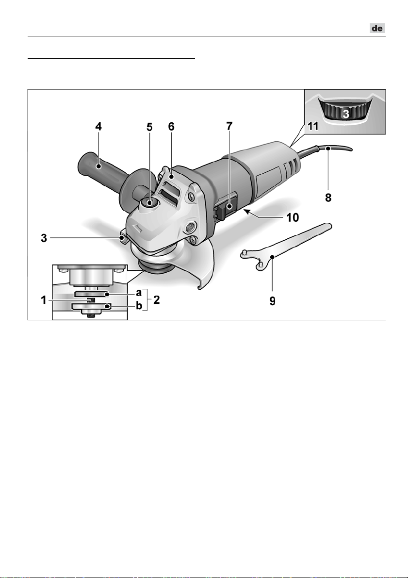
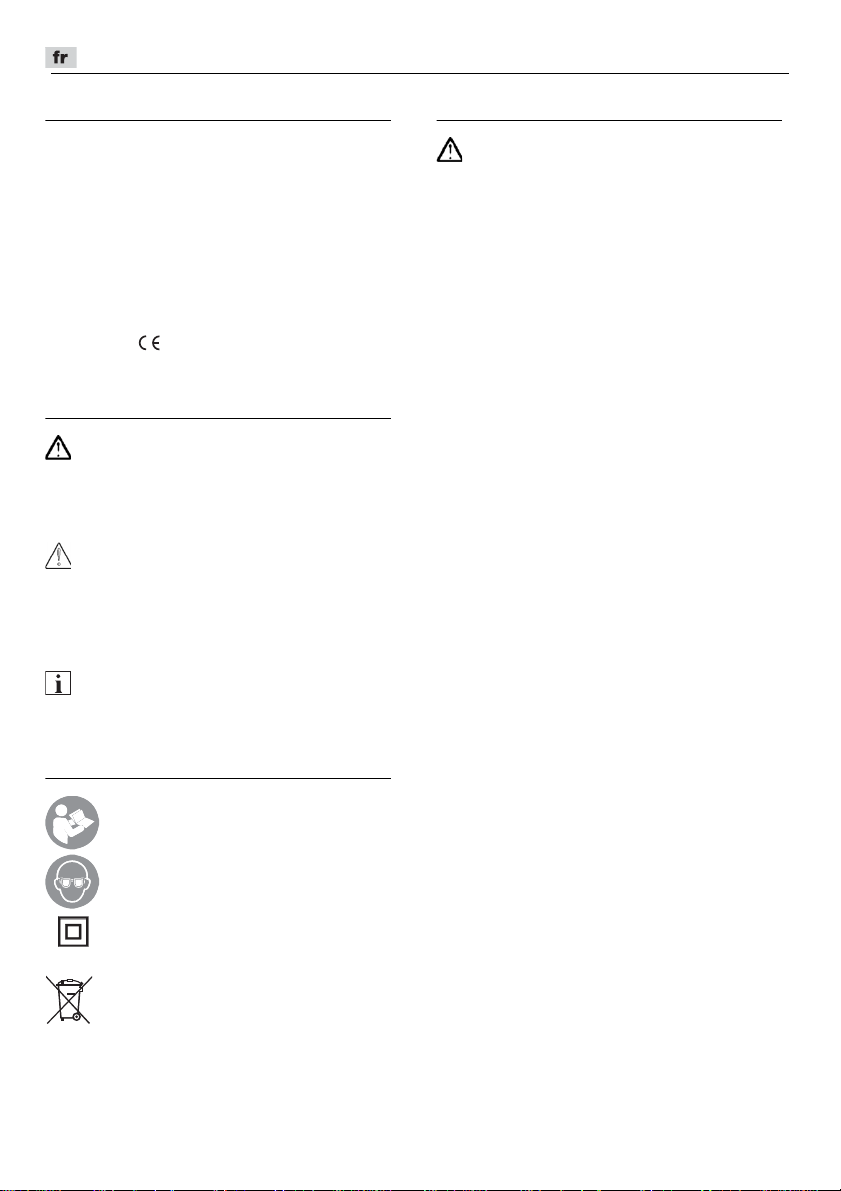
Auf einen Blick
In dieser Anleitung werden verschiedene Elektrowerkzeuge beschrieben.
Die Darstellung kann im Detail vom erworbenen Elektrowerkzeug abweichen.
1 Spindel
2 Gewindeflansch
a Spannflansch
b Spannmutter
3 Schutzhaube
4 Handgriff
Handgriff links und rechts montierbar.
5 Spindelarretierung
Zum Feststellen der Spindel beim
Werkzeugwechsel.
6 Getriebekopf
Mit Luftaustritt und Drehrichtungspfeil.
7Schalterwippe
Zum Ein- und Ausschalten. Mit
Raststellung für Dauerbetrieb.
8 Netzkabel 4,0 m mit Netzstecker
9 Stirnlochschlüssel
10 Typschild (nicht dargestellt)
11 Stellrad für Drehzahlvorwahl
(nur LE 9-10 125)
9
Page 10

L 3709 -115, L 3709 -125, LE 9-10 125, L 10-10 125, L 801, L 1001
Gebrauchsanweisung
Vor allen Arbeiten am Winkelschleifer den
WARNUNG!
Netzstecker ziehen.
Vor der Inbetriebnahme
Winkelschleifer auspacken und auf
Vollständigkeit der Lieferung und
Transportschäden kontrollieren.
Ein- und Ausschalten
Kurzzeitbetrieb ohne Einrasten:
Schalterwippe nach vorn schieben und
festhalten.
Zum Ausschalten Schalterwippe
loslassen.
Dauerbetrieb mit Einrasten:
Schalterwippe nach vorn schieben (1.)
und durch Druck auf vorderes Ende
einrasten (2.).
Zum Ausschalten Schalterwippe durch
Druck auf hinteres Ende entriegeln.
HINWEIS
Nach einem Stromausfall läuft das
eingeschaltete Gerät nicht wieder an.
Drehzahlvorwahl (nur LE 9-10 125)
Zum Einstellen der Arbeitsdrehzahl das
Stellrad auf den gewünschten Wert stellen.
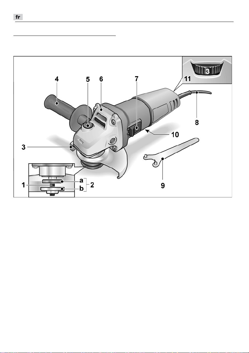
Sicherheits-Schutzhaube
(L 3709-115, L 801, L 3709-125)
Niemals ohne die Sicherheits
WARNUNG!
arbeiten.
Zur Anpassung an die Arbeitsaufgabe ist die
Sicherheits-Schutzhaube ohne Werkzeug
verstellbar.
Zum Trennen ist eine spezielle
Trennschutzhaube zu verwenden.
VORSICHT!
Verletzungsgefahr!
Schutzhandschuhe tragen.
Netzstecker ziehen.
-
Schutzhaube
10
Page 11
L 3709 -115, L 3709 -125, LE 9-10 125, L 10-10 125, L 801, L 1001
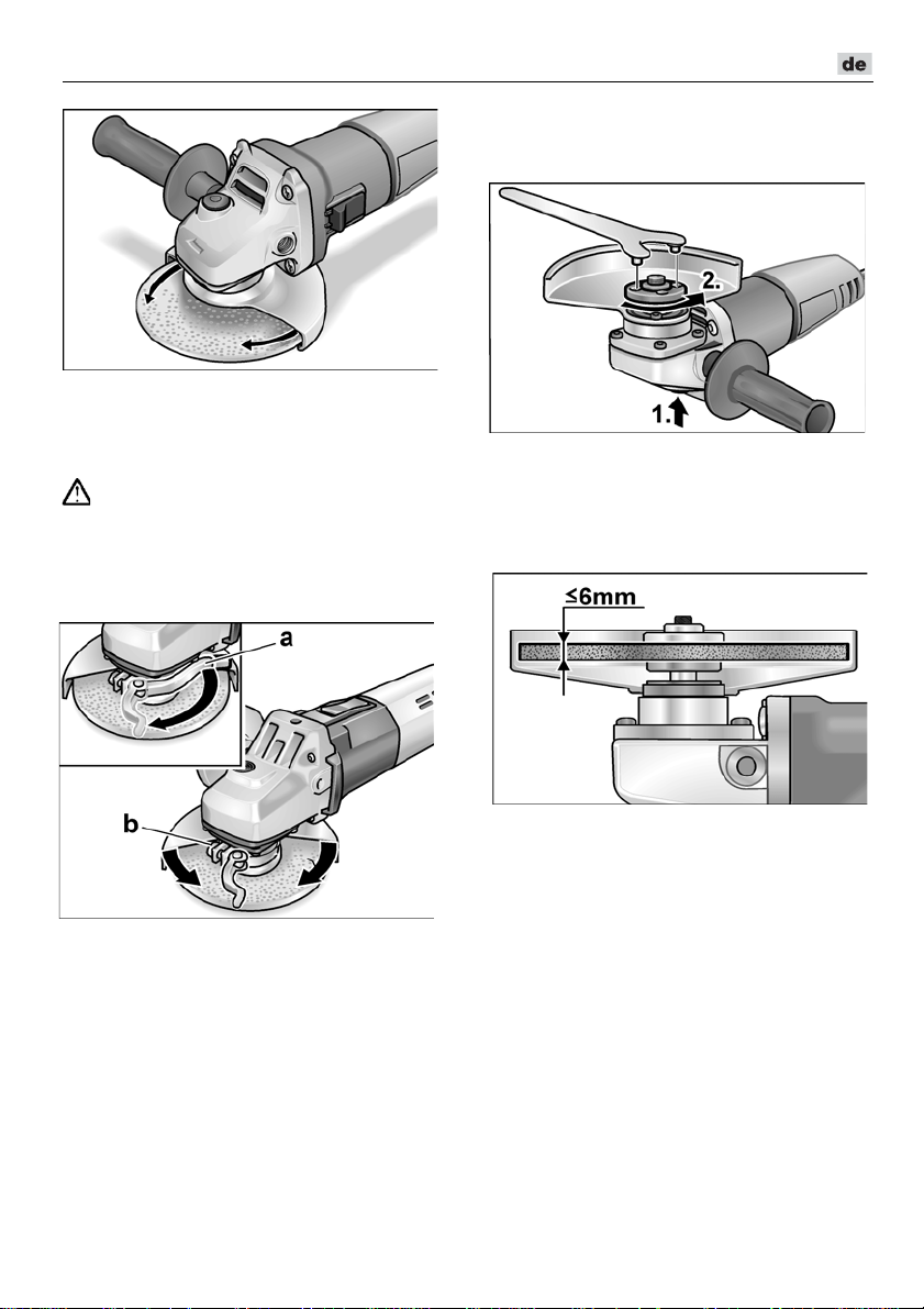
Schleifwerkzeug befestigen oder
wechseln
Netzstecker ziehen.
Sicherheits-Schutzhaube bis zur
erforderlichen Position drehen.
Schnellspannhaube (LE 9-10 125,
L10-10 125, L 1001)
WARNUNG!
Bei Schrupp
ohne Schutzhaube arbeiten.
Netzstecker ziehen.
Spannhebel (a) lösen.
Schutzhaube verstellen.
-
und Trennarbeiten niemals
Spindelarretierung drücken und gedrückt
halten (1.).
Mit Stirnlochschlüssel die Spannmutter
gegen den Uhrzeigersinn von der
Spindel lösen und abnehmen (2.).
Schleifscheibe lagerichtig einlegen.
Schraube (b) so fest anziehen, dass sich
der Spannhebel gerade noch von Hand
spannen lässt.
Spannhebel wieder festziehen.
Zum Trennen ist eine spezielle
Schnellspann-Trennschutzhaube zu
verwenden.
Spannmutter mit dem Bund nach oben
auf die Spindel schrauben.
Spindelarretierung drücken und gedrückt
halten.
Spannmutter mit dem Stirnlochschlüssel
festziehen.
Netzstecker in Steckdose stecken.
Winkelschleifer einschalten (ohne Ein-
rasten) und Winkelschleifer für ca.
30 Sekunden laufen lassen.
Auf Unwuchten und Vibrationen
kontrollieren.
Winkelschleifer ausschalten.
11
Page 12
L 3709 -115, L 3709 -125, LE 9-10 125, L 10-10 125, L 801, L 1001
Arbeitshinweise
HINWEIS
Nach dem Ausschalten läuft das
Schleifwerkzeug noch kurze Zeit nach.
Schruppschleifen
WARNUNG!
Niemals Trennscheiben zum
Schruppschleifen verwenden.
– Anstellwinkel 20–40° für besten Abtrag.
– Mit mäßigem Druck den Winkelschleifer
hin- und herbewegen. Dadurch wird das
Werkstück nicht zu heiß und es
entstehen keine Verfärbungen;
außerdem gibt es keine Rillen.
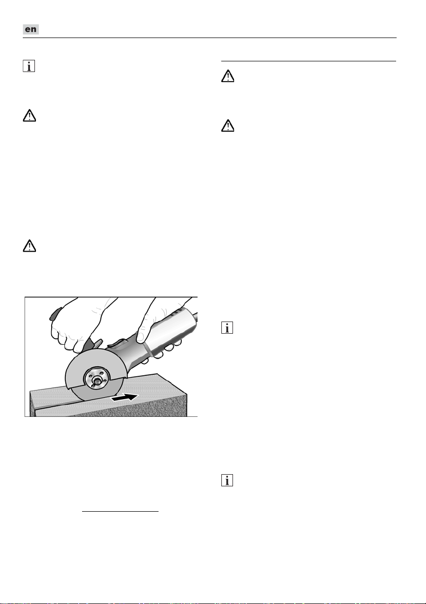
Trennschleifen
WARNUNG!
Zum Trennschleifen ist eine spezielle
Trennschutzhaube zu verwenden.
– Nicht drücken, nicht verkanten, nicht
oszillieren.
– Winkelschleifer muss stets im Gegenlauf
arbeiten. Ansonsten Gefahr des
unkontrollierten Herausspringens aus
der Rille.
– Vorschub an das zu bearbeitende
Material anpassen: je härter, desto
langsamer.
Weitere Informationen über die Produkte des
Herstellers unter www.flex-tools.com.
Wartung und Pflege
WARNUNG!
Vor allen Arbeiten am Winkelschleifer
den Netzstecker ziehen.
Reinigung
Bei der Bearbeitung von Metallen kann sich
bei extremem Einsatz leitfähiger Staub im
Gehäuseinnenraum ablagern.
Beeinträchtigung der Schutzisolierung!
Maschine über Fehlerstrom
(Auslösestrom 30 mA) betreiben.
Gerät und Lüftungsschlitze regelmäßig
reinigen. Häufigkeit ist vom bearbeiteten
Material und von der Dauer des Gebrauchs
abhängig. Gehäuseinnenraum mit Motor
regelmäßig mit trockener Druckluft
ausblasen.
Kohlenbürsten
Der Winkelschleifer ist mit Abschaltkohlen
ausgestattet.
Nach Erreichen der Verschleißgrenze der
Abschaltkohlen wird der Winkelschleifer
automatisch abgeschaltet.
Zum Austausch nur Originalteile des
Herstellers verwenden.
Bei Verwendung von Fremdfabrikaten
erlöschen die Garantieverpflichtungen des
Herstellers.
Durch die hinteren Lufteintrittsöffnungen
kann das Kohlenfeuer während des
Gebrauchs beobachtet werden.
Bei starkem Kohlenfeuer den Winkelschleifer
sofort ausschalten. Winkelschleifer an eine
vom Hersteller autorisierte
Kundendienstwerkstatt übergeben.
Getriebe
Die Schrauben am Getriebekopf während
der Garantiezeit nicht lösen.
Bei Nichtbeachtung erlöschen die
Garantieverpflichtungen des Herstellers.
WARNUNG!
HINWEIS
HINWEIS
-
Schutzschalter
12
Page 13

L 3709 -115, L 3709 -125, LE 9-10 125, L 10-10 125, L 801, L 1001
Klaus Peter Weinper
Head of Quality
Department (QD)
Eckhard Rhle
Manager Research &
Development (R & D)
Reparaturen
Reparaturen ausschließlich durch eine vom
Hersteller autorisierte
Kundendienstwerkstatt ausführen lassen.
Ersatzteile und Zubehör
Weiteres Zubehör, insbesondere
Schleifwerkzeuge und Trennschutzhauben,
den Katalogen des Herstellers entnehmen.
Explosionszeichnungen und Ersatzteillisten
finden Sie auf unserer Homepage:
www.flex-tools.com
Entsorgungshinweise
WARNUNG!
Ausgediente Geräte durch Entfernen des
Netzkabels unbrauchbar machen.
Nur für EU-Länder
Werfen Sie Elektrowerkzeuge nicht in
den Hausmüll!
Gemäss Europäischer Richtlinie 2012/19/EU
über Elektro- und Elektronik-Altgeräte und
Umsetzung in nationales Recht müssen
verbrauchte Elektrowerkzeuge getrennt
gesammelt und einer umweltgerechten
Wiederverwertung zugeführt werden.
HINWEIS
Über Entsorgungsmöglichkeiten beim
Fachhändler informieren!
-Konformität
Wir erklären in alleiniger Verantwortung,
dass das unter „Technische Daten“
beschriebene Produkt mit folgenden Normen
oder normativen Dokumenten
übereinstimmt:
EN 60745 gemäß den Bestimmungen der
Richtlinien
2011/65/EU.
Verantwortlich für technische Unterlagen:
FLEX-Elektrowerkzeuge GmbH, R & D
Bahnhofstrasse 15, D-71711 Steinheim/Murr
16.06.2016; FLEX-Elektrowerkzeuge GmbH
Bahnhofstrasse 15, D-71711 Steinheim/Murr
2014/30/EU
, 2006/42/EG,
Haftungsausschluss
Der Hersteller und sein Vertreter haften
nicht für Schäden und entgangenen Gewinn
durch Unterbrechung des
Geschäftsbetriebes, die durch das Produkt
oder die nicht mögliche Verwendung des
Produktes verursacht wurden.
Der Hersteller und sein Vertreter haften
nicht für Schäden, die durch
unsachgemäße Verwendung oder in
Verbindung mit Produkten anderer
Hersteller verursacht wurden.
13
Page 14
L 3709 -115, L 3709 -125, LE 9-10 125, L 10-10 125, L 801, L 1001
Contents
Symbols used in this manual . . . . . . . . . 14
Symbols on the power tool. . . . . . . . . . . 14
For your safety . . . . . . . . . . . . . . . . . . . 14
Noise and vibration . . . . . . . . . . . . . . . . 17
Technical specifications . . . . . . . . . . . . 18
Overview . . . . . . . . . . . . . . . . . . . . . . . . 19
Operating instructions . . . . . . . . . . . . . . 20
Maintenance and care . . . . . . . . . . . . . . 22
Disposal information . . . . . . . . . . . . . . . 23
-Declaration of Conformity . . . . . . . . 23
Exemption from liability . . . . . . . . . . . . . 23
Symbols used in this manual
WARNING!
Denotes impending danger.
Non-observance of this warning may result
in death or extremely severe injuries.
CAUTION!
Denotes a possibly dangerous situation.
Non-observance of this warning may result
in slight injury or damage to property.
NOTE
Denotes application tips and important
information.
Symbols on the power tool
Before switching on the power
tool, read the operating manual!
Wear goggles!
Protection class II
(completely insulated)
Disposal information for the old
machine (see page 23)!
For your safety
WARNING!
Before using the angle grinder, please read
and follow:
–
these operating instructions,
–
the ”General safety instructions” on the
handling of power tools in the enclosed
booklet (leaflet-no.: 315.915),
–
the currently valid site rules and the
regulations for the prevention of
accidents.
This angle grinder is state of the art and has
been constructed in accordance with the
acknowledged safety regulations.
Nevertheless, when in use, the power tool
may be a danger to life and limb of the user
or a third party, or the power tool or other
property may be damaged. The angle
grinder may be operated only if it is
–
as intended,
–
in perfect working order.
Faults which impair safety must be repaired
immediately.
Intended use
This angle grinder
– for commercial use in industry and trade,
– is designed for dry grinding and cutting
metal and stone,
– a special cutting guard is required
for cutting,
– is designed for use with grinding tools
and accessories which are indicated
in this manual or recommended by the
manufacturer and which are permitted to
run at a circumferential speed of 80 m/s.
Not permitted are e.g. chain cutting wheels,
saw blades.
Safety instructions
WARNING!
Read all safety warnings, instructions, illustrations and specifications provided with
this power tool. Failure to follow all instructions listed below may result in electric
shock, fire and/or serious injury. Save all
warnings and instructions for future
reference.
14
Page 15

L 3709 -115, L 3709 -125, LE 9-10 125, L 10-10 125, L 801, L 1001
Safety Warnings Common for Grinding
or Abrasive Cutting-Off Operations
This power tool is intended to function as
a grinder or cut-off tool. Read all safety
warnings, instructions, illustrations and
specifications provided with this power
tool.
Failure to follow all instructions listed
below may result in electric shock, fire and/
or serious injury.
Operations such as sanding, wire
brushing or polishing are not recommended to be performed with this power tool.
Operations for which the power tool was
not designed may create a hazard and
cause personal injury.
Do not use accessories which are not
specifically designed and recommended
by the tool manufacturer. J
accessory can be attached to your power
tool, it does not assure safe operation.
The rated speed of the accessory must be
at least equal to the maximum speed
marked on the power tool.
running faster than their rated speed can
break and fly apart.
The outside diameter and the thickness of
your accessory must be within the
capacity rating of your power tool.
Incorrectly sized accessories cannot be
adequately guarded or controlled.
Threaded mounting of accessories must
match the grinder spindle thread. For
accessories mounted by flanges, the
arbour hole of the accessory must fit the
locating diameter of the flange.
Accessories that do not match the
mounting hardware of the power tool will
run out of balance, vibrate excessively and
may cause loss of control.
Do not use a damaged accessory. Before
each use inspect the accessory such as
abrasive wheels for chips and cracks,
backing pad for cracks, tear or excess
wear, wire brush for loose or cracked
wires. If power tool or accessory is
dropped, inspect for damage or install an
undamaged accessory. After inspecting
and installing an accessory, position
yourself and bystanders away from the
ust because the
Accessories
plane of the rotating accessory and run the
power tool at maximum no-load speed for
one minute.
Damaged accessories will
normally break apart during this test time.
Wear personal protective equipment.
Depending on application, use face shield,
safety goggles or safety glasses. As
appropriate, wear dust mask, hearing
protectors, gloves and workshop apron
capable of stopping small abrasive or
workpiece fragments.
The eye protection
must be capable of stopping flying debris
generated by various operations. The dust
mask or respirator must be capable of
filtrating particles generated by your
operation. Prolonged exposure to high
intensity noise may cause hearing loss.
Keep bystanders a safe distance away
from work area. Anyone entering the work
area must wear personal protective
equipment.
Fragments of workpiece or of
a broken accessory may fly away and
cause injury beyond immediate area of
operation.
Hold the power tool by insulated gripping
surfaces only, when performing an
operation where the cutting accessory
may contact hidden wiring or its own cord.
Cutting accessory contacting a “live” wire
may make exposed metal parts of the
power tool “live” and could give the
operator an electric shock.
Position the cord clear of the spinning
accessory.
If you lose control, the cord
may be cut or snagged and your hand or
arm may be pulled into the spinning
accessory.
Never lay the power tool down until the
accessory has come to a complete stop.
The spinning accessory may grab the
surface and pull the power tool out of your
control.
Do not run the power tool while carrying it
at your side.
Accidental contact with the
spinning accessory could snag your
clothing, pulling the accessory into your
body.
Regularly clean the power tool’s air vents.
The motor’s fan will draw the dust inside
the housing and excessive accumulation
of powdered metal may cause electrical
hazards.
15
Page 16

L 3709 -115, L 3709 -125, LE 9-10 125, L 10-10 125, L 801, L 1001
Do not operate the power tool near
flammable materials.
Sparks could ignite
these materials.
Do not use accessories that require liquid
coolants.
Using water or other liquid
coolants may result in electrocution or
shock.
Kickback and Related Warnings
Kickback is a sudden reaction to a pinched or
snagged rotating wheel, backing pad, brush or
any other accessory. Pinching or snagging
causes rapid stalling of the rotating accessory
which in turn causes the uncontrolled power
tool to be forced in the direction opposite of the
accessory’s rotation at the point of the
binding.For example, if an abrasive wheel is
snagged or pinched by the workpiece, the
edge of the wheel that is entering into the pinch
point can dig into the surface of the material
causing the wheel to climb out or kick out. The
wheel may either jump toward or away from
the operator, depending on direction of the
wheel’s movement at the point of pinching.
Abrasive wheels may also break under these
conditions. Kickback is the result of power tool
misuse and/or incorrect operating procedures
or conditions and can be avoided by taking
proper precautions as given below.
Maintain a firm grip on the power tool and
position your body and arm to allow you to
resist kickback forces. Always use
auxiliary handle, if provided, for maximum
control over kickback or torque reaction
during start-up.
torque reactions or kickback forces, if
proper precautions are taken.
Never place your hand near the rotating
accessory.
your hand.
Do not position your body in the area
where power tool will move if kickback
occurs.
direction opposite to the wheel’s
movement at the point of snagging.
Use special care when working corners,
sharp edges etc. Avoid bouncing and
snagging the accessory.
edges or bouncing have a tendency to
snag the rotating accessory and cause
loss of control or kickback.
The operator can control
Accessory may kickback over
Kickback will propel the tool in
Corners, sharp
Do not attach a saw chain woodcarving
blade or toothed saw blade.
Such blades
create frequent kickback and loss of
control.
Safety Warnings Specific for Grinding
and Abrasive Cutting-Off Operations
Use only wheel types that are recommended for your power tool and the specific
guard designed for the selected wheel.
Wheels for which the power tool was not
designed cannot be adequately guarded
and are unsafe.
The grinding surface of centre depressed
wheels must be mounted below the plane
of the guard lip.
wheel that projects through the plane of
the guard lip cannot be adequately
protected.
The guard must be securely attached to
the power tool and positioned for
maximum safety, so the least amount of
wheel is exposed towards the operator.
The guard helps to protect the operator
from broken wheel fragments, accidental
contact with wheel and sparks that could
ignite clothing.
Wheels must be used only for recommended applications. For example: do not
grind with the side of cut-off wheel.
Abrasive cut-off wheels are intended for
peripheral grinding; side forces applied to
these wheels may cause them to shatter.
Always use undamaged wheel flanges
that are of correct size and shape for your
selected wheel.
support the wheel thus reducing the
possibility of wheel breakage. Flanges for
cut-off wheels may be different from
grinding wheel flanges.
Do not use worn down wheels from larger
power tools.
power tool is not suitable for the higher
speed of a smaller tool and may burst.
An improperly mounted
Proper wheel flanges
Wheel intended for larger
16
Page 17

L 3709 -115, L 3709 -125, LE 9-10 125, L 10-10 125, L 801, L 1001
Additional Safety Warnings specific for
Abrasive Cutting-Off Operations
Do not “jam” the cut-off wheel or apply
excessive pressure. Do not attempt to
make an excessive depth of cut.
Overstressing the wheel increases the
loading and susceptibility to twisting or
binding of the wheel in the cut and the
possibility of kickback or wheel breakage.
Do not position your body in line with and
behind the rotating wheel.
When the
wheel, at the point of operation, is moving
away from your body, the possible
kickback may propel the spinning wheel
and the power tool directly at you.
When wheel is binding or when
interrupting a cut for any reason, switch off
the power tool and hold the power tool
motionless until the wheel comes to a
complete stop.
Never attempt to remove
the cut-off wheel from the cut while the
wheel is in motion otherwise kickback may
occur. Investigate and take corrective
action to eliminate the cause of wheel
binding.
Do not restart the cutting operation in the
workpiece. Let the wheel reach full speed
and carefully re-enter the cut.
The wheel
may bind, walk up or kickback if the power
tool is restarted in the workpiece.
Support panels or any oversized
workpiece to minimize the risk of wheel
pinching and kickback.
Large workpieces
tend to sag under their own weight.
Supports must be placed under the
workpiece near the line of cut and near the
edge of the workpiece on both sides of the
wheel.
Use extra caution when making a “pocket
cut” into existing walls or other blind areas.
The protruding wheel may cut gas or water
pipes, electrical wiring or objects that can
cause kickback.
Additional safety instructions
The mains voltage and the voltage
specifications on the rating plate must
correspond.
Do not press the spindle lock until the
grinding tool stops.
Noise and vibration
NOTE
Values for the A-weighted sound pressure
level and for the total vibration values can
be found in the “Technical specifications”
table.
The noise and vibration values have been
determined in accordance with EN 60745.
CAUTION!
The indicated measurements refer to new
power tools. Daily use causes the noise and
vibration values to change.
NOTE
The vibration emission level given in this
information sheet has been measured in
accordance with a standardised test given
in EN 60745 and may be used to compare
one tool with another. It may be used for
a preliminary assessment of exposure. The
declared vibration emission level represents
the main applications of the tool. However if
the tool is used for different applications,
with different accessories or poorly
maintained, the vibration emission may
differ. This may significantly increase the
exposure level over the total working period.
However if the tool is used for different
applications, with different accessories or
poorly maintained, the vibration emission
may differ. This may significantly decrease
the exposure level over the total working
period.
Identify additional safety measures to
protect the operator from the effects of
vibration such as: maintain the tool and the
accessories, keep the hands warm,
organisation of work patterns.
CAUTION!
Wear ear protection at a sound pressure
above 85 dB(A).
17
Page 18

L 3709 -115, L 3709 -125, LE 9-10 125, L 10-10 125, L 801, L 1001
Technical specifications
Machine type
Max. grinding tool Ø
Grinding tool thickness
Tool hole diameter
Spindle thread
Speed
Power input
Power output
L 3709-115 L 3709-125
L 801
mm 115 125 125 125
mm 1–6
mm 22.23
r.p.m. 12500
W
W
750
(650 *)
450
(400 *)
12000
800 900 1010
480 530 600
LE 9-10 125 L 10-10 125
L 1001
Angle grinder
M14/WAF14
6000–11500 10000
Weight according to “EPTA
Procedure 01/2003”
kg 1,9 2,0 2,2
(without power cord)
Protection class
II/
A-weighted sound pressure level according to EN 60745 (see “Noise and vibration”):
Sound pressure level L
Sound power level L
WA
Uncertainty K
pA
dB(A)
dB(A)
db
84.6 87 91
95.6 98 102
3
Total vibration value according to EN 60745 (see “Noise and vibration”):
Emission value a
grinding surfaces
Emission value ah when
cutting-off
Uncertainty K
when
h
m/s
m/s
m/s
2
2
2
6.5 6.5 6.6
6.3 8.1 6.2
1.5
(... *) = 110 V
18
Page 19

L 3709 -115, L 3709 -125, LE 9-10 125, L 10-10 125, L 801, L 1001
Overview
1 Spindle
2 Threaded flange
a Clamping nut
b Clamping flange
3Guard
4 Handle
Handle can be fitted to the left or right.
5 Spindle lock
Secures the spindle when the tool
is changed.
6 Gear head
With air outlet and direction-of-rotation
arrow.
7 Switch rocker
Switches the power tool on and off.
With notched position for continuous
operation.
8 4.0 m power cord with plug
9 Face spanner
10 Rating plate (not illustrated)
11 Dial for preselecting the speed
(only LE 9-10 125)
19
Page 20
L 3709 -115, L 3709 -125, LE 9-10 125, L 10-10 125, L 801, L 1001
Operating instructions
Before carrying out any work on the angle
WARNING!
grinder, always pull out the mains plug.
Before switching on the power tool
Unpack the angle grinder and check that
there are no missing or damaged parts.
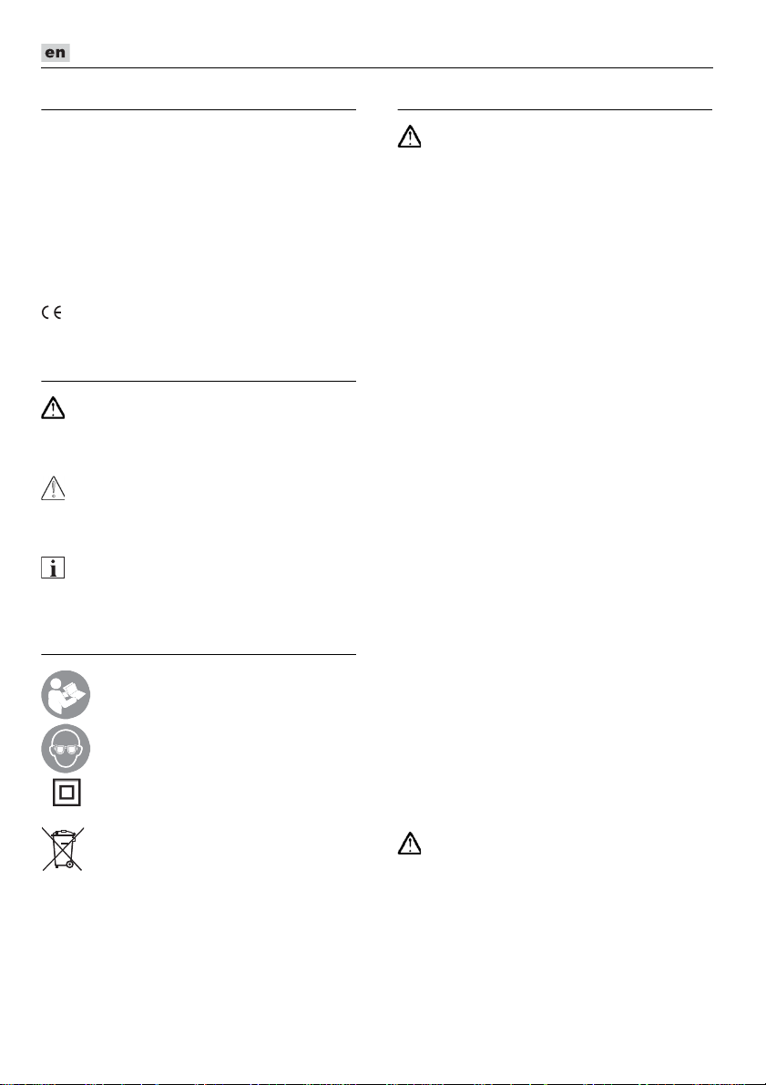
Switching on and off
Brief operation without engaged
switch rocker:
Push the switch rocker forwards and
hold in position.
To switch off the power tool, release
the switch rocker.
Continuous operation with engaged
switch rocker:
Push the switch rocker forwards (1.) and
engage by pressing the front end (2.).
To switch off the power tool, release
the switch rocker by pressing the rear
end.
NOTE
Following a power failure, the switched on
power tool does not restart.
Speed preselection
(LE 9-10 125 only)
To set the operating speed, move the dial
to the required value.
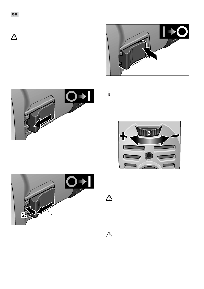
Safety guard
(L 3709-115, L 801, L 3709-125)
WARNING!
Never work without the safety guard.
The angle grinder is adapted to the job with
the safety guard which can be adjusted
without a tool.
A special cutting guard must be used
for cutting.
CAUTION!
Risk of injury! Wear protective gloves.
Pull out the mains plug.
20
Page 21
L 3709 -115, L 3709 -125, LE 9-10 125, L 10-10 125, L 801, L 1001
Attaching or changing the grinding
tool
Pull out the mains plug.
Rotate safety guard to the required
position.
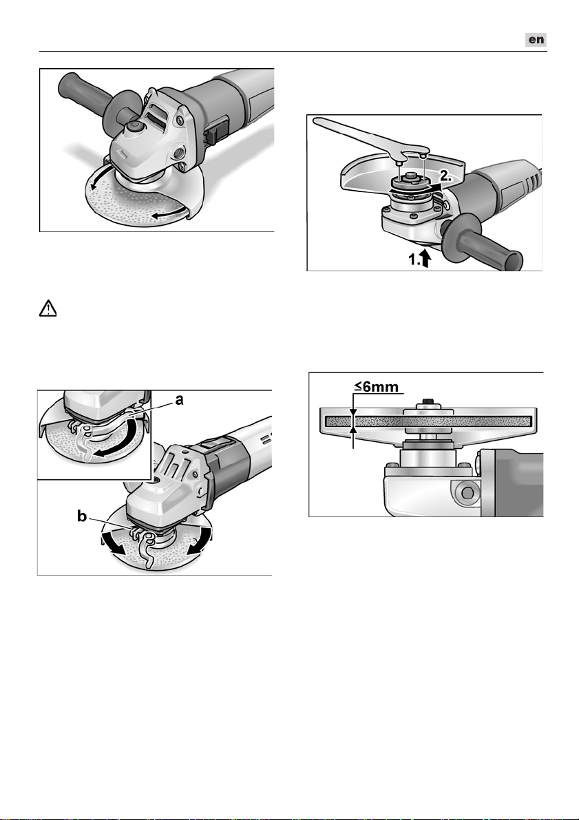
Quick-release guard
(LE 9-10 125, L 10-10 125, L 1001)
WARNING!
When using the angle grinder for roughing
or cutting, never work without the guard.
Pull out the mains plug.
Loosen the clamping lever (a).
Adjust the guard.
Press and hold down the spindle
lock (1.).
Using the face spanner, loosen the
clamping nut on the spindle in an anticlockwise direction and remove (2.).
Insert the grinding wheel in the correct
position.
Tighten screw (b) until the clamping lever
can just be clamped by hand.
Retighten the clamping lever.
A special quick-release cutting guard
must be used for cutting.
Screw the clamping nut with flange face
up, onto the spindle.
Press and hold down the spindle lock.
Tighten the clamping nut with the face
spanner.
Insert the mains plug into the socket.
Switch on the angle grinder (without
locking into position) and leave the angle
grinder running for approx. 30 seconds.
Check for imbalances and vibrations.
Switch off the angle grinder.
21
Page 22
L 3709 -115, L 3709 -125, LE 9-10 125, L 10-10 125, L 801, L 1001
Operating instructions
When the power tool is switched off, the
grinding tool continues running briefly.
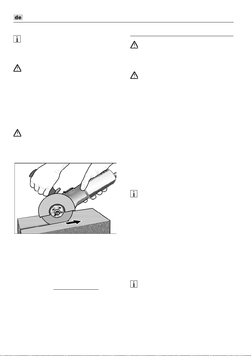
Rough-grinding
Never use cutting-off wheels for roughgrinding.
– Angle of wheel 20–40° for best cutting
– Applying moderate pressure, move
Cut-off grinding
A special cutting guard must be used
for cut-off grinding.
– Do not press, tilt or oscillate the power
– Angle grinder must always operate in the
– Adjust the feed to the material which is
For further information on the manufacturer’s
products go to www.flex-tools.com
NOTE
WARNING!
performance.
the angle grinder backwards and
forwards. As a result, the workpiece will
not become too hot and there will be no
discoloration; nor will there be any
grooves.
WARNING!
tool.
counter direction. Otherwise, there is
a risk of the angle grinder jumping
uncontrollably out of the groove.
to be work: the harder the material, the
slower the feed.
.
Maintenance and care
WARNING!
Before carrying out any work on the angle
grinder, always pull out the mains plug.
Cleaning
WARNING!
If metals are ground or cut over a prolonged
period, conductive dust may become
deposited inside the housing. Impairment of
the protective insulation! Operate the power
tool via a residual-current-operated circuitbreaker (tripping current 30 mA).
Regularly clean the power tool and
ventilation slots. Frequency of cleaning is
dependent on the material and duration of
use.
Regularly blow out the housing interior and
motor with dry compressed air.
Carbon brushes
The angle grinder features cut-off carbon
brushes.
When the wear limit of the cut-off carbon
brushes is reached, the angle grinder
switches off automatically.
NOTE
Use only original parts supplied by the
manu-facturer for replacement purposes.
If non-original parts are used, the guarantee
obligations of the manufacturer will be
deemed null and void.
When the power tool is being used, the
carbon brushes can be seen sparking
through the rear air inlet apertures.
If the carbon brushes spark excessively,
switch off the angle grinder immediately.
Take the angle grinder to a customer service
workshop authorised by the manufacturer.
Gears
NOTE
Do not loosen the screws on the gear head
during the warranty period.
Non-compliance will deem the guarantee
obligations of the manufacturer null and
void.
22
Page 23

L 3709 -115, L 3709 -125, LE 9-10 125, L 10-10 125, L 801, L 1001
Klaus Peter Weinper
Head of Quality
Department (QD)
Eckhard Rhle
Manager Research &
Development (R & D)
Repairs
Repairs may be carried out by an authorised
customer service centre only.
Spare parts and accessories
Other accessories, in particular sanding
tools and cutting guards, can be found
in the manufacturer's catalogues.
Exploded drawings and spare-part lists can
be found on our homepage:
www.flex-tools.com
Disposal information
WARNING!
Render redundant power tools unusable
by removing the power cord.
EU countries only
Do not throw electric power tools
into the household waste!
In accordance with the European Directive
2012/19/EU on Waste Electrical and
Electronic Equipment and transposition into
national law used electric power tools must
be collected separately and recycled in an
environmentally friendly manner.
NOTE
Please ask your dealer about disposal
options!
-Declaration of Conformity
We declare under our sole responsibility that
the product described under “Technical
specifications” conforms to the following
standards or normative documents:
EN 60745 in accordance with the
regulations of the directives
2014/30/EU, 2006/42/EC, 2011/65/EU.
Responsible for technical documents:
FLEX-Elektrowerkzeuge GmbH, R & D
Bahnhofstrasse 15, D-71711 Steinheim/Murr
16.06.2016; FLEX-Elektrowerkzeuge GmbH
Bahnhofstrasse 15, D-71711 Steinheim/Murr
Exemption from liability
The manufacturer and his representative are
not liable for any damage and lost profit due
to interruption in business caused by the
product or by an unusable product.
The manufacturer and his representative are
not liable for any damage which was caused
by improper use of the power tool or by use
of the power tool with products from other
manufacturers.
23
Page 24
L 3709 -115, L 3709 -125, LE 9-10 125, L 10-10 125, L 801, L 1001
Table des matières
Symboles utilisés . . . . . . . . . . . . . . . . . . 24
Symboles apposés sur l’appareil . . . . . . 24
Pour votre sécurité . . . . . . . . . . . . . . . . 24
Bruit et vibrations . . . . . . . . . . . . . . . . . . 28
Données techniques . . . . . . . . . . . . . . . 29
Vue d’ensemble . . . . . . . . . . . . . . . . . . . 30
Instructions d’utilisation . . . . . . . . . . . . . 31
Maintenance et nettoyage . . . . . . . . . . . 33
Consignes pour la mise au rebut . . . . . . 34
Conformité . . . . . . . . . . . . . . . . . . . . 34
Exclusion de responsabilité . . . . . . . . . . 34
Symboles utilisés
AVERTISSEMENT !
Ce symbole prévient d’un danger imminent ;
le non-respect des consignes qui le suivent
s’accompagne d’un danger de mort ou de
blessures très graves.
PRUDENCE !
Ce symbole désigne une situation
potentiellement dangereuse. Si vous ne
respectez pas cette consigne, vous risquez
de vous blesser ou de causer des dégâts
matériels.
REMARQUE
Ce symbole vous donne des conseils
d’utilisation et des informations importantes.
Symboles apposés sur l’appareil
Avant la mise en service, veuillez
lire la notice d’instructions !
Portez des lunettes
de protection !
Classe de protection II
(complètement isolé)
Consignes pour la mise au
rebut de l’ancien appareil
(voir page 34) !
Pour votre sécurité
AVERTISSEMENT !
Avant d’utiliser cette meuleuse d’angle,
veuillez lire les documents suivants et
respecter leurs contenus :
–
La présente notice d’utilisation,
–
les « Consignes générales de sécurité »
régissant l’emploi des appareils
électriques et réunies dans le fascicule
ci-joint (référence : 315.915),
–
les règles et prescriptions préventives
des accidents applicables sur le lieu
de mise en œuvre.
Cette meuleuse d’angle a été construite
conformément à l’état actuel de la technique
et en respectant les règles techniques de
sécurité reconnues. Toutefois, de son
emploi peut émaner un danger de mort et un
risque de blessures graves pour l’utilisateur
ou les tiers, ou un risque d’endommager la
machine elle-même ou d’autres objets de
valeur. Cette meuleuse d’angle ne pourra
servir
–
qu’à des fins conformes à l’usage prévu,
–
dans un état technique et de sécurité
parfait.
Supprimez immédiatement tout
dérangement susceptible de compromettre
la sécurité.
Conformité d’utilisation
Cette meuleuse d’angle est destinée
– aux utilisations professionnelles dans
l’industrie et l’artisanat,
– à meuler et sectionner du métal et de la
pierre par meulage à sec,
– pour tronçonner, il faut utiliser un capot
protecteur spécial,
– à servir équipée d’un outil de meulage et
des accessoires indiqués dans la
présente notice ou recommandés par le
fabricant et homologués pour supporter
une vitesse circonférentielle de 80 m/s.
Le montage de meules de fraisage à chaîne
et de lames de scie est interdit.
24
Page 25

L 3709 -115, L 3709 -125, LE 9-10 125, L 10-10 125, L 801, L 1001
Consigne de sécurité
AVERTISSEMENT !
Lire tous les avertissements de sécurité, les
instructions, les illustrations et les spécifications fournis avec cet outil électrique.
Ne pas suivre les instructions énumérées
ci
-
dessous peut provoquer un choc électrique, un incendie et/ou une blessure
sérieuse. Conserver tous les avertissements et toutes les instructions pour pouvoir
s'y reporter ultérieurement.
Avertissements de sécurité communs
pour les opérations de meulage et de
tronçonnage par meule abrasive
Il faut utiliser cet outil électroportatif
comme ponceuse et tronçonneuse
à disque. Lire toutes les mises en garde
de sécurité, les instructions, les illustrations et les spécifications fournies avec
cet outil électrique. Le fait de ne pas
suivre toutes les instructions données cidessous peut provoquer un choc
électrique, un incendie et / ou une
blessure grave
Cet outil électrique ne permet pas de
poncer avec du papier abrasif, de travailler
avec des brosses à crins métalliques et de
polir.
Les opérations pour lesquelles l’outil
électrique n’a pas été conçu peuvent
provoquer un danger et causer un
accident corporel
Ne pas utiliser d’accessoires non conçus
spécifiquement et recommandés par
le fabricant d’outils.
Le simple fait que l’accessoire puisse
être fixé à votre outil électrique ne garantit pas un fonctionnement en toute
sécurité.
La vitesse assignée de l’accessoire
doit être au moins égale à la vitesse
maximale indiquée sur l’outil électrique.
Les accessoires fonctionnant plus vite
que leur vitesse assignée peuvent
se rompre et voler en éclat.
Le diamètre extérieur et l’épaisseur
de votre accessoire doivent se situer
dans le cadre des caractéristiques
de capacité de votre outil électrique.
.
.
Les accessoires dimensionnés de façon
incorrecte ne peuvent pas être protégés
ou commandés de manière appropriée.
Le montage fileté d’accessoires doit être
adapté au filet de l’arbre de la meuleuse.
Pour les accessoires montés avec des
flasques, l’alésage central de l’accessoire doit s’adapter correctement au
diamètre du flasque. Les accessoires qui
ne correspondent pas aux éléments de
montage de l’outil électrique seront en
déséquilibre, vibreront de manière
excessive et pourront provoquer une
perte de contrôle.
Ne pas utiliser d’accessoire endommagé.
Avant chaque utilisation examiner les
accessoires comme les meules abrasives
pour détecter la présence éventuelle de
co-peaux et fissures, les patins d’appui
pour détecter des traces éventuelles de
fissures, de déchirure ou d’usure excessive, ainsi que les brosses métalliques
pour détecter des fils desserrés ou
fissurés.
Si l’outil électrique ou l’outil
monté chutent, vérifiez s’ils sont
endommagés ou utilisez un outil intact.
Après avoir contrôlé et monté l’outil,
faites tourner l’appareil pendant une
minute à la vitesse maximale en vous
tenant, vous et d’autres personnes
proches de vous, loin du plan de l’outil
installé en train de tourner.
Les accessoires endommagés seront
normalement détruits pendant cette
période d’essai.
Porter un équipement de protection
individuelle. En fonction de l’application,
utiliser un écran facial, des lunettes
de sécurité ou des verres de sécurité.
Si nécessaire, portez un masque à poussière, un casque anti-bruit, des gants
de protection ou une blouse spéciale
faisant barrage aux particules poncées
et de matière.
La protection oculaire doit être capable
d’arrêter les débris volants produits
par les diverses opérations. Le masque
antipoussières ou le respirateur doit être
capable de filtrer les particules produites
par vos travaux. L’exposition prolongée
aux bruits de forte intensité peut
provoquer une perte de l’audition.
25
Page 26

L 3709 -115, L 3709 -125, LE 9-10 125, L 10-10 125, L 801, L 1001
Maintenir les personnes présentes à une
distance de sécurité par rapport à la zone
de travail. Toute personne entrant dans
la zone de travail doit porter un équipement de protection individuelle.
Des fragments de pièce à usiner ou d’un
accessoire cassé peuvent être projetés
et provoquer des blessures en dehors
de la zone immédiate d’opération.
Ne tenez l’appareil que par ses poignées
isolantes lors de travaux au cours desquels l’outil installé risque de toucher des
câbles électriques invisibles ou le cordon
d’alimentation de l’appareil.
Le contact avec une ligne électrique
peut mettre les pièces métalliques sous
tension et provoquer une électrocution.
Placer le câble éloigné de l’accessoire
de rotation.
Si vous perdez le contrôle, le câble peut
être coupé ou subir un accroc et votre
main ou votre bras peut être tiré dans
l’accessoire de rotation.
Ne jamais reposer l’outil électrique avant
que l’accessoire n’ait atteint un arrêt
complet.
L’accessoire de rotation peut agripper
la surface et arracher l’outil électrique
hors de votre contrôle.
Ne pas faire fonctionner l’outil électrique
en le portant sur le côté.
Un contact accidentel avec l’accessoire
de rotation pourrait accrocher vos vêtements et attirer l’accessoire sur vous.
Nettoyer régulièrement les orifices
d’aération de l’outil électrique.
Le ventilateur du moteur attirera la poussière à l’intérieur du boîtier et une
accumulation excessive de poudre
de métal peut provoquer des dangers
électriques.
Ne pas faire fonctionner l’outil électrique
à proximité de matériaux inflammables.
Des étincelles pourraient enflammer
ces matériaux.
N’utilisez jamais d’outils requérant
un liquide de refroidissement.
L’utilisation d’eau ou d’autres liquides
de efroidissement peut provoquer une
électrocution.
Rebonds et mises en garde
correspondantes
Un recul brutal est la réaction qu’engendre
un outil en train de tourner (meule, plateau
de ponçage, brosse à crins métalliques,
etc.) et qui vient subitement d’accrocher
un objet ou de se bloquer. Un accrochage
ou blocage provoque un arrêt brutal de
l’outil installé qui était en train de tourner.
De ce fait, un outil électroportative non
fermement tenue subit une accélération
en sens opposé de celui de l’outil installé.
Si p. ex. une meule se coince ou se bloque
dans la pièce, l’arête qui plonge dans
la pièce peut stopper brutalement et provoquer la cassure de la meule ou un recul
brutal. Dans ce cas, la meule se déplace
dans un sens la rapprochant ou l’éloignant
de l’opérateur, tout dépend du sens dans
lequel la meule tournait à l’endroit où elle
s’est bloquée. Ce phénomène peut faire
casser les meules.
Le recul brutal est engendré par une utilisation erronée ou inexperte de l’outil
électrique. Le rebond résulte d’un mauvais
usage de l’outil et / ou de procédures ou de
conditions de fonctionnement incorrectes et
peut être évité en prenant les précautions
appropriées spécifiées ci-dessous.
Maintenir fermement l’outil électrique
et placer votre corps et vos bras pour
vous permettre de résister aux forces
de rebond. Toujours utiliser une poignée
auxiliaire, le cas échéant, pour une maîtrise maximale du rebond ou de la réaction de couple au cours du démarrage.
L’opérateur peut maîtriser les couples
de réaction ou les forces de rebond,
si les précautions qui s’imposent sont
prises.
Ne jamais placer votre main à proximité
de l’accessoire en rotation.
L’accessoire peut effectuer un rebond
sur votre main.
Ne pas vous placer dans la zone
où l’outil électrique se déplacera
en cas de rebond.
Le choc du recul force l’outil électrique
à tourner en direction opposée à celle
de la meule à l’endroit où cette dernière
s’est bloquée.
26
Page 27

L 3709 -115, L 3709 -125, LE 9-10 125, L 10-10 125, L 801, L 1001
Apporter un soin particulier lors de tra-
vaux dans les coins, les arêtes vives etc.
Eviter les rebondissements et les accrochages de l’accessoire.
En tournant, l’outil en place tend
à se coincer dans les angles, au contact
d’arêtes vives ou en cas d’impact.
Ceci provoque une perte de contrôle
ou un recul brutal.
Ne pas fixer de chaîne coupante,
de lame de sculpture sur bois, de chaîne
coupante ni de lame de scie dentée.
De telles lames provoquent des rebonds
fréquents et des pertes de contrôle.
Consignes de sécurité particulières
pour le ponçage et le tronçonnage
Utilisez exclusivement les moyens
de ponçage homologués pour aller
avec votre outil électrique, ainsi
que le capot protecteur prévu pour
ce moyen de ponçage.
Les moyens de ponçage qui ne sont pas
prévus pour cet outil électrique ne pourront pas être suffisamment protégés
et ne sont donc pas sûrs à l’emploi.
La surface de meulage des meules à moyeu déporté doit être montée sous le plan
de la lèvre du protecteur.
montée de manière incorrecte qui dépasse du plan de la lèvre du protecteur ne
peut pas être protégée de manière
appropriée.
Le protecteur doit être solidement fixé
à l’outil électrique et placé en vue d’une
sécurité maximale, de sorte que l’opérateur soit exposé le moins possible à la
meule.
Le protecteur permet de protéger
l’opérateur des fragments de meule
cassée, d’un contact accidentel avec la
meule et d’étincelles susceptibles
d’enflammer les vêtements.
Il ne faut utiliser les meules que dans les
domaines d’application recommandés.
Exemple : Ne poncez jamais avec
les flancs d’un disque de tronçonnage.
Sur les disques de tronçonnage, seule
la tranche du disque sert à abraser
de la matière. L’application d’une force
latérale sur ces moyens de ponçage
peut les faire se briser.
Une meule
Utilisez toujours des brides de serrage
intactes, ayant la taille et la forme
correctement adaptées au disque
de ponçage que vous avez choisi.
Des brides appropriées soutiennent
le disque de ponçage et réduisent
ainsi le risque de cassure du disque.
Les brides affectées aux disques de
tronçonnage peuvent différer des brides
affectées aux disques de ponçage.
N’utilisez jamais de disques de ponçage
usés provenant de plus gros outils
électroportatifs. Les disques de ponçage
installés sur de plus gros outils
électroportatifs n’ont pas été conçus pour
les vitesses plus élevées offertes par les
petits outils électroportatifs, ils risquent
donc de casser.
Consignes de sécurité particulières
additionnelles pour le tronçonnage
Évitez que le disque de tronçonnage
se bloque et de lui imprimer une pression
d’applique excessive. N’exécutez pas de
coupes excessivement profondes.
Une surcharge du disque de tronçonnage accroît la contrainte qu’il subit ;
il risque plus de se coincer ou de se
bloquer, ce qui accroît le risque d’un
recul brutal donc d’une cassure du
disque.
Évitez la zone située devant et derrière
le disque de tronçonnage en rotation.
Lorsque vous déplacez le disque
de tronçonnage, dans la pièce, dans
la direction l’éloignant de vous, l’outil
électrique risque en cas de recul brutal
d’être catapulté dans votre direction
avec le disque toujours en rotation.
Si le disque de tronçonnage se coince
ou si vous interrompez le travail pour
une raison quelconque, éteignez l’outil
électrique et tenez-le calmement
en main jusqu’à ce que le disque
se soit entièrement immobilisé.
Ne tentez jamais de sortir de la pièce le
disque encore en rotation, car ce dernier
risque de provoquer un recul brutal.
Déterminez la cause du coincement
et supprimez-la.
27
Page 28

L 3709 -115, L 3709 -125, LE 9-10 125, L 10-10 125, L 801, L 1001
Ne rallumez pas l’outil électrique tant
que le disque se trouve dans la pièce.
Avant d’entamer prudemment le tronçonnage, attendez que le disque
ait atteint sa pleine vitesse.
Le disque risquerait sinon de se coincer,
de sauter hors de la pièce ou de provoquer un recul brutal.
Étayez les dalles et pièces de grande
taille pour éviter le risque que le disque
de tronçonnage, en se coinçant dedans,
ne provoque un recul brutal.
Les grandes pièces peuvent s’incurver
sous leur poids propre. Il faut soutenir
la pièce sur les deux côtés du disque de
tronçonnage, à savoir aussi bien à proximité de la fente de tronçonnage que sur
les bords extérieurs de la pièce.
Soyez particulièrement prudent lors
des « coupes en poche » dans les
murs existants ou dans d’autres zones
n’offrant pas une visibilité complète.
Le disque de tronçonnage plongeant
dans la surface risque, s’il sectionne
des conduites de gaz ou d’eau,
des lignes électriques ou d’autres objets,
de provoquer un recul brutal.
Autres consignes de sécurité
La tension du secteur et celle indiquée
sur la plaque signalétique doivent
concorder.
N’appuyez sur le dispositif de blocage de
la broche que lorsque la meuleuse
ne tourne pas.
Bruit et vibrations
REMARQUE
Les valeurs du niveau de bruit exprimé en
décibels A ainsi que les valeurs totales des
vibrations figurent dans le tableau
« Données techniques ».
Les niveaux de bruits et vibrations ont été
déterminés conformément à EN 60745.
PRUDENCE !
Les valeurs de mesure indiquées s’appliquent aux appareils neufs. Pendant la mise
en œuvre quotidienne, les valeurs de bruit
et de vibrations varient.
Le niveau de vibrations indiqué dans ces
REMARQUE
instructions a été mesuré selon un procédé
standardisé dans la norme EN 60745,
et peut servir à comparer les outils électroportatifs entre eux. Ce procédé convient
également pour estimer provisoirement
la contrainte en vibrations.
Le niveau de vibrations indiqué se réfère
aux principales applications de l’outil électrique. Le niveau de vibrations représente
les principales formes d’utilisation de l’outil
électrique. Si toutefois ce dernier est utilisé
à d’autres fins, avec des outils montés
différents ou s’il ne subit qu’une maintenance insuffisante, le niveau de vibrations
pourra dévier de ce qui est indiqué.
Cela peut accroître nettement la contrainte
en vibrations sur l’ensemble de la période
de travail.
Pour une estimation précise de la contrainte
en vibrations, il faudrait également tenir
compte des temps au cours desquels
l’appareil est éteint ou bien de ceux au cours
desquels il tourne certes, mais que l’utilisateur ne s’en sert pas. Cela peut réduire
nettement la contrainte en vibrations
sur l’ensemble de la période de travail.
Pour protéger l’utilisateur contre les effets
des vibrations, définissez des mesures
de sécurité supplémentaires, dont par
exemple : Maintenance de l’outil électrique
et des outils installés, maintien des mains
au chaud, organisation des séquences
de travail.
PRUDENCE !
Lorsque la pression acoustique dépasse
85 dB(A), veuillez porter un casque
antibruit.
28
Page 29

L 3709 -115, L 3709 -125, LE 9-10 125, L 10-10 125, L 801, L 1001
Données techniques
L 3709-115 L 3709-125
LE 9-10 125 L 10-10 125
L 801
Type d’appareil Meuleuse d’angle
Ø max. de l’outil de meulage
Epaisseur de l’outil de meulage
Alésage réceptacle
Filetage de broche
Vitesse
Puissance absorbée
Puissance débitée
mm 115 125 125 125
mm 1–6
mm 22,23
M14
tr / mn
W
W
12500
750 (650 *)
450 (400 *)
12000
800 900 1010
480 530 600
6000–11500 10000
Poids conforme à
„EPTA-procedure
kg 1,9 2,0 2,2
1/2003“ (sans le cordon)
Classe de protection
II/
Niveau de bruit exprimé en décibels A correspondant à EN 60745
(voir « Bruit et vibrations ») :
Niveau de pression acoustique
L
pA
Niveau de puissance sonore
L
WA
Marge d’incertitude K
dB(A)
dB(A)
db
84,6 87 91
95,6 98 102
3
Valeur totale des vibrations correspondant à EN 60745
(voir « Bruit et vibrations ») :
Valeur émissive ah pendant
le ponçage de surfaces
Valeur émissive ah pendant le
tronçonnage
Marge d’incertitude K
m/s
m/s
m/s
2
2
2
6,5 6,5 6,6
6,3 8,1 6,2
1,5
(... *) = 110 V
L 1001
29
Page 30
L 3709 -115, L 3709 -125, LE 9-10 125, L 10-10 125, L 801, L 1001
Vue d’ensemble
Cette notice d’instructions décrit différents modèles d’outils portatifs.
Dans le détail, les illustrations peuvent différer de l’appareil acheté.
1 Broche
2 Flasque taraudé
a Ecrou de serrage
b Bride de serrage
3 Capot de protection
4 Poignée
La poignée peut se monter à gauche
et à droite.
5 Dispositif de blocage de la broche
Ce dispositif sert à bloquer la broche
lors d’un changement d’outil.
6 Boîte d’engrenages
Avec sortie d’air et flèche
directionnelle.
30
7 Interrupteur à bascule
Pour allumer et éteindre l’appareil.
Avec cran de maintien enclenché.
8 Cordon d’alimentation électrique
de 4,0 m, terminé par une fiche mâle.
9 Clé à ergots
10 Plaque signalétique (non représenté)
11 Molette de préréglage de la vitesse
(LE 9-10 125 seulement)
Page 31

L 3709 -115, L 3709 -125, LE 9-10 125, L 10-10 125, L 801, L 1001
Instructions d’utilisation
Avant d’effectuer tous travaux sur la
AVERTISSEMENT !
meuleuse d’angle, débranchez la fiche mâle
de la prise de courant.
Avant la mise en service
Déballez la meuleuse d’angle, vérifiez que
la livraison est au complet et qu’elle ne
comporte aucun dégâts dus au transport.
Allumage et extinction
Marche de courte durée, sans activer
le cran d’arrêt :
Poussez l’interrupteur à bascule vers
l’avant et maintenez-le en position.
Pour éteindre, relâchez l’interrupteur
àbascule.
Marche permanente avec encrantage :
Poussez l’interrupteur à bascule vers
l’avant (1.) puis appuyez sur sa partie
avant (2.).
Pour éteindre l’appareil, appuyez
sur la partie arrière de l’interrupteur.
REMARQUE
Après une coupure de courant, l’appareil
ne redémarre pas même s’il se trouvait
en position enclenchée.
Présélection de la vitesse
(LE 9-10 125 seulement)
Pour régler la vitesse de travail, amenez la
molette sur le chiffre souhaité.
Capot de protection de sécurité
(L 3709-115, L 801, L 3709-125)
AVERTISSEMENT !
Ne travaillez jamais sans capot protecteur
de sécurité.
Le capot protecteur de sécurité se déplace
sans outil, et s’adapte ainsi à la tâche à
réaliser.
Pour tronçonner, il faut utiliser un capot
protecteur spécial.
PRUDENCE !
Risque de blessures!
Portez des gants de protection.
Débranchez la fiche mâle de la prise
de courant.
31
Page 32
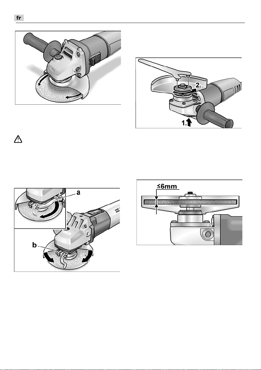
L 3709 -115, L 3709 -125, LE 9-10 125, L 10-10 125, L 801, L 1001
Tournez le capot protecteur de sécurité
pour l’amener sur la position requise.
Capot à serrage rapide
(LE 9-10 125, L 10-10 125, L 1001)
AVERTISSEMENT !
Lors de travaux de dégrossissage
et de sectionnement, ne travaillez
jamais sans capot de protection.
Débranchez la fiche mâle de la prise
de courant.
Desserrez le levier de serrage (a).
Déplacez le capot de protection.
Fixez l’outil de meulage
ou changez-le
Débranchez la fiche mâle de la prise
de courant.
Appuyez sur le dispositif de blocage
de la broche et maintenez-le appuyé (1.).
A l’aide de la clé à ergots, tournez l’écrou
de serrage en sens inverse des aiguilles
d’une montre pour le détacher de la
broche, puis retirez-le (2.).
Posez le disque de meulage dans la
bonne position.
Serrez la vis (b) ce qu’il faut pour que le
levier de serrage se laisse encore tout
juste serrer à la main.
Resserrez à fond le levier de serrage.
Pour tronçonner, il faut utiliser un capot
protecteur spécial à serrage rapide.
32
Vissez l’écrou de serrage (1b) sur la
broche avec le collet vers le haut.
Appuyez sur le dispositif de blocage
de la broche et maintenez-le appuyé.
Serrez l’écrou avec la clé à ergots.
Branchez la fiche mâle dans la prise
de courant.
Enclenchez la meuleuse d’angle (sans
utiliser le cran d’arrêt) puis laissez-la
marcher pendant env. 30 secondes.
Contrôlez l’absence de balourds
et de vibrations.
Eteignez la meuleuse d’angle.
Page 33
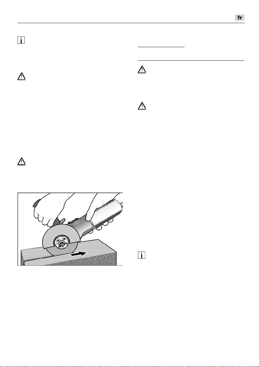
L 3709 -115, L 3709 -125, LE 9-10 125, L 10-10 125, L 801, L 1001
Consignes de travail
REMARQUE
Après que vous avez éteint l’appareil, l’outil
de meulage continue de tourner
brièvement.
Meulage de dégrossissage
AVERTISSEMENT !
N’utilisez jamais de disque à tronçonner
pour dégrossir des pièces.
– Présentez l’outil selon un angle de 20°
à 40°. A cette inclinaison, l’abrasion est
maximale.
– Imprimez un mouvement de va-et-vient
à la meuleuse d’angle en appuyant
modérément. Ceci empêche la pièce
de surchauffer et aucune décoloration
n’apparaît.
En outre, aucune rainure ne se forme.
Tronçonner des pièces
AVERTISSEMENT !
Pour tronçonner, il faut utiliser un capot
de protection spécial.
– N’appuyez pas sur l’outil, ne le coincez
pas, ne le faites pas osciller.
– La meuleuse d’angle doit toujours
travailler à contresens. Si vous ne
contrez pas le sens de progression
naturel, la meuleuse sortira brutalement
de la rainure.
– Adaptez la vitesse d’avance antagoniste
à la matière que vous êtes en train
de travailler. Plus la matière est dure et
plus il faudra progresser lentement.
Vous trouverez des informations avancées
sur les produits du fabricant à l’adresse
www.flex-tools.com
.
Maintenance et nettoyage
AVERTISSEMENT !
Avant d’effectuer tous travaux sur la
meuleuse d’angle, débranchez la fiche mâle
de la prise de courant.
Nettoyage
AVERTISSEMENT !
Lors du travail des métaux dans des
conditions d’emploi intensives, de la
poussière électroconductrice peut se
déposer à l’intérieur du boîtier de la
ponceuse.
Détérioration de l’isolation protectrice !
Ne raccordez l’appareil qu’à une prise
protégée par un disjoncteur différentiel
réagissant dès une intensité différentielle de
30 mA.
Nettoyez régulièrement l’appareil et les ouïes
de ventilation. La fréquence des nettoyages
dépend du matériau et de la durée
d’utilisation.
Nettoyez régulièrement l’intérieur du boîtier
et le moteur à l’aide d’air comprimé sec.
Balais de charbon
La meuleuse d’angle est équipée de balais
de charbon qui, au-delà d’une certaine limite
d’usure, empêchent le moteur de démarrer.
Une fois la limite d’usure atteinte, la
meuleuse d’angle s’éteint automatiquement.
REMARQUE
Ne remplacez ces balais que par des pièces
d’origine fournies par le fabricant.
En cas d’emploi de pièces d’autres
marques, le fabricant déclinera toute
obligation au titre du recours en garantie.
Les ouïes d’entrée d’air situées à l’arrière
permettent, pendant l’utilisation, de surveiller
les étincelles des balais sur le collecteur.
En présence d’une forte densité d’étincelles,
éteignez immédiatement la meuleuse.
Renvoyez-la à un atelier du service aprèsvente (SAV) agréé par le fabricant.
33
Page 34

L 3709 -115, L 3709 -125, LE 9-10 125, L 10-10 125, L 801, L 1001
Klaus Peter Weinper
Head of Quality
Department (QD)
Eckhard Rhle
Manager Research &
Development (R & D)
Réducteur
REMARQUE
Pendant la période de garantie, ne dévissez
pas les vis situées contre la boîte
d’engrenages. En cas de non-respect de
cette consigne, le fabricant déclinera toute
obligation au titre du recours en garantie.
Réparations
Ne confiez les réparations qu’à un atelier
de SAV agréé par le fabricant.
Pièces de rechange et accessoires
D’autres accessoires, notamment les outils
de meulage, figurent dans le catalogue
du fabricant.
Vous trouverez des vues éclatées et des
listes de pièces de rechange sur notre
site Web : www.flex-tools.com
Consignes pour la mise au rebut
AVERTISSEMENT !
Lorsque les appareils ont fini de servir,
enlevez leur cordon d’alimentation
électrique pour les rendre inutilisables.
Pays de l’UE uniquement
Ne mettez pas les outils électriques
à la poubelle des déchets
domestiques !
Conformément à la directive européenne
2012/19/UE visant les appareils électriques
et électroniques usagés, et à sa transposition en droit national, les outils électriques
ne servant plus devront être collectés
séparément et introduits dans un circuit de
recyclage respectueux de l’environnement.
REMARQUE
Pour connaître les possibilités de mise au
rebut, veuillez consulter votre revendeur
spécialisé.
Conformité
Nous déclarons sous notre responsabilité
exclusive que le produit décrit à la rubrique
« Données techniques » se conforme aux
normes ou aux documents normatifs
suivants :
EN 60745 conformément aux dispositions
énoncées dans les directives
2014/30/UE, 2006/42/CE, 2011/65/UE.
Responsables de la documentation
technique :
FLEX-Elektrowerkzeuge GmbH, R & D
Bahnhofstrasse 15, D-71711 Steinheim/Murr
16/06/2016; FLEX-Elektrowerkzeuge GmbH
Bahnhofstrasse 15, D-71711 Steinheim/Murr
Exclusion de responsabilité
Le fabricant et son représentant ne pourront
être tenus responsables des dommages et
du bénéfice perdu en raison d’une
interruption du fonctionnement de l
provoqués par le produit ou par
l’impossibilité de l’utiliser.
Le fabricant et son représentant ne pourront
être tenus responsables des dommages
provoqués par une utilisation inexperte du
produit ou par son utilisation en association
avec les produits d’autres fabricants.
’
affaire,
34
Page 35
L 3709 -115, L 3709 -125, LE 9-10 125, L 10-10 125, L 801, L 1001
Indice
Simboli utilizzati . . . . . . . . . . . . . . . . . . . 35
Dati tecnici . . . . . . . . . . . . . . . . . . . . . . . 40
Guida rapida . . . . . . . . . . . . . . . . . . . . . 41
Per la vostra sicurezza . . . . . . . . . . . . . 35
Rumore e vibrazione . . . . . . . . . . . . . . . 39
Istruzioni per l’uso . . . . . . . . . . . . . . . . . 42
Manutenzione e cura . . . . . . . . . . . . . . . 44
Istruzioni per la rottamazione
e lo smaltimento . . . . . . . . . . . . . . . . . . 45
Conformità . . . . . . . . . . . . . . . . . . . . 45
Esclusione della responsabilità . . . . . . . 45
Simboli utilizzati
PERICOLO!
Indica un pericolo imminente.
In caso d’inosservanza dell’avvertenza,
pericolo di morte o di ferite gravi.
PRUDENZA!
Indica una situazione eventualmente
pericolosa. In caso d’inosservanza
dell’avviso, pericolo di ferite o danni
materiali.
AVVISO
Indica consigli per l’impiego ed informazioni
importanti.
Simboli sull’apparecchio
Prima della messa in funzione
leggere le istruzioni per l’uso!
Indossare occhiali protettivi!
Classe di protezione II
(isolato completamente)
Avviso per la rottamazione
dell’apparecchio dimesso
(vedi pagina 45)!
Per la vostra sicurezza
PERICOLO!
Prima di usare la smerigliatrice angolare,
leggere e comportarsi secondo:
–
queste istruzioni per l’uso,
–
le «Istruzioni di sicurezza generali»
per l’uso di elettroutensili, nell’accluso
fascicolo (Scritti N°: 315.915),
–
le regole e le norme per la prevenzione
degli infortuni vigenti nel luogo d’impiego.
Questa smerigliatrice angolare è costruita
secondo l’attuale stato della tecnica e le
regole tecniche di sicurezza riconosciute.
Tuttavia nel suo impiego possono derivare
pericoli per l’incolumità e la vita dell’utilizzatore e di terzi, nonché danni alla macchina
o ad altri beni materiali. La smerigliatrice
angolare deve essere impiegata solo
–
per l’uso regolare previsto,
–
in perfetto stato tecnico di sicurezza.
Eliminare immediatamente i guasti che
pregiudicano la sicurezza.
Uso regolare
Questa smerigliatrice angolare è prevista
–per l’impiego professionale nell'industria
– per smerigliare e troncare metallo e
–per l
Non sono ammessi per es., dischi per
fresatrici a catena, lame da sega.
’
artigianato,
enell
pietra con taglio a secco; per la
troncatura è necessaria una speciale
cuffia di protezione da taglio,
’
impiego con utensile abrasivo
ed accessori indicato in questo libretto
di istruzioni o consigliato dal produttore
ed autorizzato per una velocità periferica
di 80 m/s.
35
Page 36

L 3709 -115, L 3709 -125, LE 9-10 125, L 10-10 125, L 801, L 1001
Istruzioni di sicurezza
PERICOLO!
Leggere tutte le avvertenze di sicurezza,
le istruzioni con relative illustrazioni e le
specifiche fornite con l’utensile elettrico.
La mancata ottemperanza alle avvertenze
e alle istruzioni può dare luogo a scosse
elettriche, a incendi e/o a lesioni serie.
Conservare tutte le avvertenze di sicurezza
e le istruzioni per poterle consultare in
futuro.
Istruzioni di sicurezza generali per
lavori di levigatura e troncatura
Utilizzare questo elettroutensile come
levigatrice e troncatrice.
Osservare tutte le istruzioni di sicurezza,
indicazioni, illustrazioni e dati consegnati
con l’apparecchio. In caso di mancata
osservanza delle istruzioni seguenti,
possibilità di scossa elettrica, incendio
e/o lesioni gravi.
Questo elettroutensile non è idoneo per la
smerigliatura con carta abrasiva, per lavori
con spazzole metalliche e per lucidare.
Gli impieghi, per i quali l’elettroutensile non
è previsto, possono causare pericoli
e lesioni
Non usare accessori, che non siano stati
espressamente previsti e raccomandati
dal costruttore per questo elettroutensile.
Il solo fatto che l’accessorio può essere
fissato a questo elettroutensile non
garantisce un uso sicuro.
Il numero di giri consentito dell’utensile
montato deve essere come minimo
uguale al numero di giri massimo
indicato sull’elettroutensile.
L’accessorio che gira ad una velocità
superiore a quella consentita può frantumarsi ed essere proiettato tutt’intorno.
Il diametro esterno e lo spessore
dell’utensile montato devono corrispondere alle dimensioni indicate dell’elettroutensile.
Gli utensili con caratteristiche sbagliate
non possono essere schermati o controllati adeguatamente.
.
Accessori con filetto riportato devono
essere adatti in modo preciso alla
filettatura dell’alberino. Negli accessori
che vengono montati tramite flangia, il
diametro del foro dell’accessorio deve
corrispondere al diametro di
alloggiamento della flangia. Accessori
che non vengono fissati in modo preciso
all’elettroutensile non ruotano in modo
uniforme, vibrano molto forte e possono
provocare la perdita del controllo.
Non impiegare utensili danneggiati.
Prima di ogni utilizzo controllare i portautensili e gli accessori ed accertarsi che
sui dischi abrasivi non vi siano scheggiature o crepature, che il platorello non sia
soggetto ad incrinature, crepature o forte
usura e che le spazzole metalliche non
abbiano fili metallici allentati oppure rotti.
In caso di caduta dell’elettroutensile
o dell’utensile, controllare se hanno
subito danni, o montare un utensile
di lavoro privo di danni. Dopo avere
controllato e montato l’utensile di lavoro,
allontanare le persone che sono nelle
vicinanze dal piano di rotazione
dell’utensile e fare girare l’apparecchio
per un minuto al massimo numero di giri.
In questo tempo di prova, gli utensili
montati che presentano danni per
lo più si rompono.
Indossare l’equipaggiamento protettivo
personale. A seconda dell’impiego,
usare la protezione integrale per il viso,
la protezione per gli occhi oppure occhiali
protettivi.
Se necessario, indossare la maschera
antipolvere, la protezione per l’udito,
guanti protettivi o il grembiule speciale,
che impedisce il contatto con piccole
particelle di abrasivo e di materiale.
Gli occhi devono essere protetti contro
corpi estranei volanti, che hanno origine
in diversi impieghi. La maschera antipolvere o maschera di respirazione deve
filtrare la polvere che si sviluppa durante
l’impiego. In caso di lunga esposizione
a forte rumore, vi è la possibilità di danni
all’udito.
36
Page 37

L 3709 -115, L 3709 -125, LE 9-10 125, L 10-10 125, L 801, L 1001
In presenza di altre persone, prestare
attenzione alla loro distanza di sicurezza
dalla vostra zona di lavoro.
Chiunque entri nella zona di lavoro deve
indossare l’equipaggiamento protettivo
personale.
Frammenti di materiale lavorato o di
utensili montati che si rompono possono
essere proiettati e causare anche lesioni
all’esterno dell’area di lavoro diretta.
Quando si eseguono lavori, durante
i quali l’utensile montato potrebbe
toccare linee elettriche nascoste oppure
il suo stesso cavo di alimentazione, afferrare l’elettroutensile solo sulle superfici
di presa isolate.
Il contatto con una linea elettrica sotto
tensione può mettere sotto tensione
anche le parti metalliche dell’elettroutensile e provocare una scossa elettrica.
Tenere il cavo di alimentazione lontano
da utensili montati in rotazione.
In caso di perdita del controllo dell’apparecchio, il cavo di alimentazione potrebbe essere troncato oppure potrebbe
avvolgersi sull’utensile in rotazione avvicinandolo così alla vostra mano oppure
al braccio.
Non deporre mai l’elettroutensile, prima
che l’utensile montato sia completamente fermo.
L’utensile montato in rotazione può
entrare in contatto con la superficie
di appoggio, causando così la perdita
del vostro controllo sull’elettroutensile.
Non tenere l’elettroutensile in funzione
durante il trasporto.
A causa del contatto accidentale con
l’utensile in rotazione il vostro abbigliamento s’impiglia nell’utensile e così
lo avvicina e lo fa penetrare nel vostro
corpo.
Pulire regolarmente le fessure di ventila-
zione dell’elettroutensile.
La ventola del motore attira la polvere
nella carcassa, ed un forte accumulo
di polvere metallica può causare pericoli
elettrici.
Non usare l’elettroutensile in prossimità
di materiali infiammabili.
Le scintille possono incendiare questi
materiali.
Non usare utensili montati, che richie-
dono l’impiego di refrigeranti liquidi.
L’impiego di acqua o di altri liquidi
di raffreddamento può causare una
scossa elettrica.
Contraccolpo e corrispondenti
istruzioni di sicurezza
Il contraccolpo è l’improvvisa reazione
di un utensile montato in rotazione che
s’incastra o si blocca, come disco abrasivo,
mola a tazza, spazzola metallica ecc.
L’incastrarsi o bloccarsi provoca un arresto
improvviso dell’utensile in rotazione.
A causa di ciò un elettroutensile, che non
è mantenuto saldamente, subisce nel punto
di arresto un’accelerazione nel senso
di rotazione contrario a quello dell’utensile
montato.
Se ad es. una mola s’inceppa o incastra
nel pezzo, il bordo della mola immersa nel
pezzo può restare incastrato e provocare
così la rottura della mola o oppure un
contraccolpo. La mola si avvicina in tal caso
all’operatore o si allontana da lui, a seconda
del senso di rotazione della mola nel punto
di arresto. In tal caso le mole possono
anche rompersi.
Un contraccolpo è la conseguenza di un uso
errato o imperfetto dell’elettroutensile.
Esso può essere impedito per mezzo
di idonee precauzioni, come in seguito
descritto.
Afferrare saldamente l’elettroutensile
e assumere con il corpo e le braccia
una posizione, nella quale sia possibile
intercettare le forze di contraccolpo.
Se disponibile, usare sempre l’impugnatura supplementare, al fine di avere
il massimo controllo possibile sulle forze
di contraccolpo o sulle coppie di reazione
durante l’accelerazione.
Attraverso idonee precauzioni, l’operatore riesce a controllare le forze
di contraccolpo e di reazione.
Non avvicinare mai la mano agli utensili
in rotazione.
In caso di contraccolpo l’utensile impiegato può raggiungere la mano.
37
Page 38

L 3709 -115, L 3709 -125, LE 9-10 125, L 10-10 125, L 801, L 1001
Evitare con il proprio corpo la zona, verso
la quale l’elettroutensile si muove in caso
di un contraccolpo.
Il contraccolpo spinge l’elettroutensile in
direzione opposta al senso di rotazione
della mola nel punto di arresto.
Lavorare con precauzione particolare
negli angoli, sugli spigoli vivi, ecc.
Impedire il rimbalzo o il bloccarsi
dell’utensile montato sulla superficie
lavorata.
L’utensile in rotazione tende ad
incastrarsi in prossimità di angoli,
spigoli acuti oppure in caso di rimbalzo.
Questo provoca una perdita di controllo
oppure un contraccolpo.
Non impiegare lame per seghe a catena
o lame per sega dentate.
Questi utensili provocano spesso in
contraccolpo o la perdita di controllo
sull’elettroutensile.
Avvertenze di sicurezza speciali
per la levigatura e troncatura
Usare esclusivamente mole approvate
per questo elettroutensile e la cuffia
di protezione prevista per queste mole.
Le mole non previste per questo elettroutensile non possono essere adeguatamente schermate e perciò non sono
sicure.
Dischi abrasivi piegati a gomito devono
essere montati in modo tale che la loro
superficie abrasiva non sporga oltre il
piano del bordo della cuffia di protezione.
Un disco abrasivo montato in modo non
corretto che sporge dal piano del bordo
della cuffia di protezione non può essere
schermato sufficientemente.
La cuffia di protezione deve essere
applicata in modo sicuro all’elettroutensile
e deve essere regolata in modo tale da
poter garantire il massimo possibile di
sicurezza, questo significa che la parte
dell’utensile abrasivo rivolta verso
l’operatore, deve essere ridotta al minimo
possibile.
l’operatore da frammenti, da contatto
accidentale con l’utensile abrasivo nonché
da scintille che possono far prendere fuoco ai vestiti.
La cuffia di protezione protegge
Usare le mole solo per le possibilità
d’impiego raccomandate. Ad esempio:
non levigare mai con la superficie
laterale di una mola per troncare.
Le mole per troncare sono destinate
all’asportazione di materiale con il bordo
della mola. L’effetto di forza laterale
su questi corpi abrasivi può provocarne
la rottura.
Usare sempre flange di serraggio prive
di danni, della grandezza e forma adatte
alla mola scelta.
Le flange adatte supportano la mola
riducendo così il pericolo della sua
rottura. Flange e mole per troncare
possono essere diverse dalle flange
per altri tipi di mole abrasive.
Non utilizzare mole consumate
di elettroutensili più grandi.
Le mole per elettroutensili più grandi non
sono previste per le maggiori velocità
di rotazione degli elettroutensili più
piccoli e possono rompersi.
Ulteriori avvertenze di sicurezza
speciali per la troncatura
Evitare il bloccaggio del disco da taglio
oppure una pressione di spinta eccessiva. Non eseguire tagli eccessivamente
profondi.
Un sovraccarico del disco da taglio
aumenta la sollecitazione su di esso
e la sua tendenza ad inclinarsi o bloccarsi e di conseguenza la possibilità
di un contraccolpo o della rottura del
corpo abrasivo.
Mantenersi a distanza dalla zona avanti
e dietro al disco da taglio in rotazione.
Quando muovete il disco da taglio nel
pezzo con movimento in allontanamento
dal vostro corpo, in caso di un rimbalzo
l’elettroutensile può essere scaraventato
direttamente verso di voi con il disco
in rotazione.
38
Page 39

L 3709 -115, L 3709 -125, LE 9-10 125, L 10-10 125, L 801, L 1001
Se il disco si blocca o se interrompete
il lavoro, spegnete l’elettroutensile
e mantenetelo in posizione sul pezzo
finché il disco non si è completamente
fermato.
Non cercate mai di estrarre il disco
ancora in rotazione dall’interno del taglio,
altrimenti vi è pericolo di un contraccolpo.
In caso di bloccaggio accertare ed eliminare la causa.
Non riaccendere l’elettroutensile quando
il disco è ancora nell’interno del pezzo.
Attendere che il disco da taglio abbia
raggiunto la massima velocità, prima
di riprendere con precauzione il taglio.
Altrimenti il disco può incepparsi,
saltare fuori dal pezzo o causare
un contraccolpo.
Per evitare il rischio di contraccolpo a
causa dell’incepparsi del disco da taglio,
sostenere le piastre o i grandi pezzi
lavorati.
I pezzi grandi possono flettersi sotto
il loro stesso peso. Il pezzo deve essere
sostenuto sui entrambi i lati del disco
da taglio, vale a dire sia in prossimità
del taglio sia dei bordi.
Prestare molta attenzione nei «tagli
a tasca» in esistenti pareti o in altre
zone non visibili.
Il disco da taglio durante l’immersione,
nel taglio di tubazioni del gas o dell’acqua, di condutture elettriche o di altri
oggetti può provocare un contraccolpo.
Ulteriori avvertenze di sicurezza
La tensione di rete e l’indicazione di
tensione sulla targhetta d’identificazione
devono coincidere.
Premere l’arresto dell’alberino solo
quando l’utensile di rettifica è fermo.
Rumore e vibrazione
AVVISO
I valori per il livello di rumore stimato A
ed i valori totali di vibrazione risultano
dalla tabella „Dati tecnici“.
I valori di rumore e vibrazione sono stati
rilevati secondo EN 60745.
PRUDENZA!
I valori di misura indicati sono validi solo per
apparecchi nuovi. Nell’impiego quotidiano
i valori di rumore e vibrazione cambiano.
AVVISO
Il livello di vibrazioni indicato in queste
istruzioni è stato misurato conformemente
ad un procedimento di misura standardizzato in EN 60745 e può essere utilizzato
per il confronto tra elettroutensili.
Esso è idoneo anche per una valutazione
temporanea della sollecitazione da vibrazioni. Il livello di vibrazioni indicato rappresenta gli impieghi principali dell’elettroutensile. Se tuttavia l’elettroutensile viene
impiegato per altri usi, con diverso utensile
montato o manutenzione insufficiente,
il livello di vibrazioni può differire.
Questo può aumentare notevolmente
la sollecitazione da vibrazioni per tutta
la durata del lavoro.
Per un’esatta stima della sollecitazione
da vibrazioni si devono considerare anche
i tempi, nei quali l’apparecchio è spento
oppure è in funzione, ma non è effettivamente impiegato. Questo può ridurre notevolmente la sollecitazione da vibrazioni
per tutto il periodo di lavoro.
Per proteggere l’operatore dall’effetto delle
vibrazioni, stabilire misure di sicurezza
aggiuntive, come ad esempio: manutenzione dell’elettroutensile e degli utensili
impiegati, riscaldamento delle mani,
organizzazione delle procedure di lavoro
PRUDENZA!
In caso di pressione acustica superiore
a 85 dB(A) indossare la protezione
acustica.
.
39
Page 40

Dati tecnici
L 3709 -115, L 3709 -125, LE 9-10 125, L 10-10 125, L 801, L 1001
L 3709-115 L 3709-125
L 801
LE 9-10 125 L 10-10 125
L 1001
Tipo di apparecchio Smerigliatrice angolare
Max. Ø utensile di rettifica
Spessore utensile di rettifica
Foro di montaggio
Filettatura del mandrino
Giri
Potenza assorbita
Potenza resa
Peso secondo la „EPTA-
procedure 1/2003“ (senza cavo)
Classe di protezione
mm 115 125 125 125
mm 1–6
mm 22,23
M14
rpm 12500
12000
6000–11500 10000
W 750 800 900 1010
W 450 480 530 600
kg 1,9 2,0 2,2
II/
Livello rumore stimato A conforme alla norma EN 60745 (vedi «Rumore e vibrazione»):
Livello di pressione acustica L
Livello di potenza acustica L
Insicurezza K
WA
pA
dB(A)
dB(A)
db
84,6 87 91
95,6 98 102
3
Valore totale di vibrazione conforme alla norma EN 60745 (vedi «Rumore e vibrazione»):
Valore di emissione a
rettifica di superfici
Valore di emissione ah nella
troncatura
Insicurezza K
nella
h
m/s
m/s
m/s
2
2
2
6,5 6,5 6,6
6,3 8,1 6,2
1,5
40
Page 41
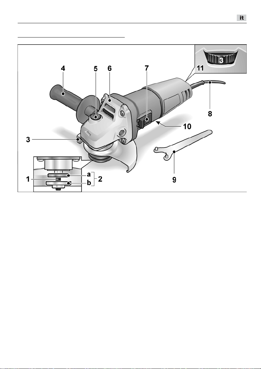
L 3709 -115, L 3709 -125, LE 9-10 125, L 10-10 125, L 801, L 1001
Guida rapida
1Alberino
2 Flangia filettata
a Dado di serraggio
b Flangia di serraggio
3 Cuffia di protezione
4Maniglia
Impugnatura montabile a sinistra
edestra.
5 Arresto alberino
Per bloccare l’alberino nella
sostituzione dell’utensile di rettifica.
6 Testa ingranaggi
Con uscita aria e freccia per il senso
di rotazione.
7 Bilico dell’interruttore
Per accendere e spegnere.
Con posizione di arresto per servizio
continuo.
8 Cavo d’alimentazione 4,0 m con spina
9 Chiave a pioli
10 Targhetta d’identificazione
(non rappresentato)
11 Rotella di regolazione per presele-
zione velocità (solo LE 9-10 125)
41
Page 42

Istruzioni per l’uso
L 3709 -115, L 3709 -125, LE 9-10 125, L 10-10 125, L 801, L 1001
Prima di qualsiasi lavoro alla smerigliatrice
PERICOLO!
angolare, estrarre la spina d’alimentazione.
Prima della messa in funzione
Disimballare la smerigliatrice angolare
e controllare la completezza della fornitura
e l’eventuale presenza di danni di trasporto.
Accendere e spegnere
Servizio discontinuo senza arresto
del bilico:
Spingere il bilico dell’interruttore verso
avanti e mantenerlo.
Per spegnere rilasciare il bilico dell’inter-
ruttore.
Servizio continuo con arresto del bilico:
Per spegnere, sbloccare il bilico
dell’interruttore premendo sull’estremità
posteriore.
AVVISO
Dopo un’interruzione dell’alimentazione
elettrica, l’apparecchio rimasto acceso
non si rimette in funzione.
Preselezione del numero di giri
(solo LE 9-10 125)
Spingere il bilico dell’interruttore verso
avanti (1.) ed arrestarlo con una
pressione sull’estremità anteriore (2.).
42
Per la regolazione del numero di giri di
lavoro, disporre la rotella di regolazione sul
valore desiderato.
Cuffia di protezione di sicurezza
(L 3709-115, L 801, L 3709-125)
PERICOLO!
Non lavorare mai senza la cuffia protettiva
di sicurezza.
Per l’adattamento al compito di lavoro, la
cuffia di protezione di sicurezza è regolabile
senza utensile.
Per la troncatura utilizzare una speciale
cuffia di protezione da taglio.
PRUDENZA!
Pericolo di ferite! Indossare guanti protettivi.
Estrarre la spina d’alimentazione.
Page 43

L 3709 -115, L 3709 -125, LE 9-10 125, L 10-10 125, L 801, L 1001
Fissare o sostituire la mola
Estrarre la spina d’alimentazione.
Ruotare la cuffia di protezione di
sicurezza nella posizione necessaria.
Cuffia a serraggio rapido
(LE 9-10 125, L 10-10 125, L 1001)
PERICOLO!
Nei lavori di sgrosso e troncatura non
lavorare mai senza cuffia di protezione.
Estrarre la spina d’alimentazione.
Allentare la leva di bloccaggio (a).
Spostare la cuffia di protezione.
Premere l’arresto dell’alberino e mante-
nerlo premuto (1.).
Con la chiave a pioli svitare il dado
di serraggio dall’alberino in senso
antiorario e smontarlo (2.).
Inserire la mola nella posizione corretta.
Stringere la vite (b) con forza tale che la
leva di serraggio possa essere ancora
stretta a mano.
Stringere di nuovo la leva di serraggio.
Per la troncatura utilizzare una speciale
cuffia di protezione da taglio a montaggio
rapido.
Avvitare sull’alberino il dado di serraggio
(1b) con il collare rivolto verso l’alto.
Premere l’arresto dell’alberino (5) e
mantenerlo premuto.
Stringere il dado di serraggio con
la chiave a pioli.
Inserire la spina d’alimentazione nella
presa.
Accendere la smerigliatrice angolare
(senza arresto) e tenerla in funzione
per ca. 30 secondi.
Controllare eventuali squilibri e
vibrazioni.
Spegnere la smerigliatrice angolare.
43
Page 44

L 3709 -115, L 3709 -125, LE 9-10 125, L 10-10 125, L 801, L 1001
Istruzioni per il lavoro
Dopo lo spegnimento l’utensile di rettifica
continua a ruotare brevemente per inerzia.
Rettifica di sgrosso
Per la rettifica di sgrosso non usare mai
mole per troncare.
– Per la migliore asportazione, angolo
– Muovere la smerigliatrice angolare con
Taglio con la mola
Per troncare deve essere usata una
speciale cuffia di protezione da taglio.
– Non premere, non inclinare lateralmente,
– La smerigliatrice angolare deve lavorare
– Adeguare l’avanzamento al tipo di
Altre informazioni sui prodotti del produttore
www.flex-tools.com
AVVISO
PERICOLO!
d’incidenza 20°–40°.
moderata pressione in avanti e indietro.
Ciò facendo il pezzo non si riscalda
eccessivamente e non subentrano
alterazioni di colore; inoltre non si
formano rigature.
PERICOLO!
non oscillare.
sempre in controrotazione.
Altrimenti sussiste pericolo di salto
incontrollato fuori dalla fessura di taglio.
materiale da lavorare: quanto più duro,
tanto più lentamente.
.
Manutenzione e cura
PERICOLO!
Prima di qualsiasi lavoro alla smerigliatrice
angolare, estrarre la spina d’alimentazione.
Pulizia
PERICOLO!
Nella lavorazione di metalli, in caso
d’impiego in condizioni estreme, nell’interno
della carcassa può accumularsi polvere
conduttrice.
Pregiudizio per l’isolamento protettivo!
Collegare la machina tramite un interruttore
differenziale (corrente di scatto 30 mA).
Pulire regolarmente l’apparecchio e le fessure di ventilazione. La frequenza dipende
dal materiale lavorato e dalla durata dell’uso.
Soffiare regolarmente con aria compressa
secca l’interno della carcassa con il motore.
Spazzole di carbone
La smerigliatrice angolare è dotata di
spazzole di carbone di sicurezza.
Quando il limite di usura delle spazzole
è stato raggiunto, la smerigliatrice angolare
si disinserisce automaticamente.
AVVISO
Per la sostituzione usare solo parti originali
del produttore. In caso di uso di prodotti
d’altra provenienza si estinguono i doveri di
garanzia del produttore.
Attraverso le aperture di entrata aria
posteriori si può osservare lo scintillio delle
spazzole durante il funzionamento.
Se lo scintillio è eccessivo, spegnere
immediatamente la smerigliatrice angolare.
Affidare la smerigliatrice angolare ad
un’officina del servizio assistenza clienti
autorizzata dal produttore.
Meccanismo
AVVISO
Durante il periodo di garanzia, non svitare le
viti sulla testa ingranaggi . In caso
d’inosservanza si estinguono i doveri
di garanzia del produttore.
44
Page 45

L 3709 -115, L 3709 -125, LE 9-10 125, L 10-10 125, L 801, L 1001
Klaus Peter Weinper
Head of Quality
Department (QD)
Eckhard Rhle
Manager Research &
Development (R & D)
Riparazioni
Fare eseguire le riparazioni esclusivamente
da un’officina del servizio assistenza clienti
autorizzata dal produttore.
Ricambi ed accessori
Per altri accessori, specialmente utensili
di rettifica, consultare i cataloghi del produttore.
Per i disegni esplosi e le liste dei ricambi
consultare il nostro sito: www.flex-tools.com
Istruzioni per la rottamazione
e lo smaltimento
PERICOLO!
Rendere inservibili gli apparecchi fuori
uso eliminando il cavo d’alimentazione.
Solo per paesi dell’UE
Non gettare elettroutensili nei rifiuti
domestici!
Secondo la Direttiva europea 2012/19/CE
sui rifiuti di apparecchiature elettriche ed
elettroniche e sua conversione nel diritto
nazionale, gli elettroutensili dimessi devono
essere raccolti separatamente ed avviati ad
un riciclaggio ecologico.
AVVISO
Informarsi presso il rivenditore specializzato
sulle possibilità di rottamazione.
Conformità
Dichiariamo sotto nostra esclusiva responsabilità, che il prodotto descritto sotto
«Dati tecnici» è conforme alle seguenti
norme o documenti normativi:
EN 60745 ai sensi delle disposizioni
delle direttive 2014/30/UE,
2006/42/CE, 2011/65/UE.
Il responsabile della documentazione tecnica:
-
Elektrowerkzeuge GmbH, R & D
FLEX
Bahnhofstrasse 15, D-71711 Steinheim/Murr
16/06/2016; FLEX
Bahnhofstrasse 15, D
-
Elektrowerkzeuge GmbH
-
71711 Steinheim/Murr
Esclusione della responsabilità
Il produttore ed il suo rappresentante
non rispondono di danni e lucro cessante
derivanti da interruzione dell’esercizio
dell’attività causata dal prodotto o da
impossibilità d’utilizzazione del prodotto.
Il produttore ed il suo rappresentante non
rispondono di danni causati da impiego
inappropriato o in collegamento con prodotti
di altri produttori.
45
Page 46

L 3709 -115, L 3709 -125, LE 9-10 125, L 10-10 125, L 801, L 1001
Contenido
Símbolos empleados . . . . . . . . . . . . . . . 46
Símbolos en el aparato . . . . . . . . . . . . . 46
Para su seguridad . . . . . . . . . . . . . . . . . 46
Ruidos y vibraciones . . . . . . . . . . . . . . . 50
Datos técnicos . . . . . . . . . . . . . . . . . . . . 51
De un vistazo . . . . . . . . . . . . . . . . . . . . . 52
Indicaciones para el uso . . . . . . . . . . . . 53
Mantenimiento y cuidado . . . . . . . . . . . 55
Indicaciones para la depolución . . . . . . 56
Conformidad . . . . . . . . . . . . . . . . . . 56
Exclusión de la garantía . . . . . . . . . . . . 56
Símbolos empleados
¡ADVERTENCIA!
Indica un peligro inminente. En caso de
incumplimiento, existe peligro de muerte o
lesiones de la mayor gravedad.
¡CUIDADO!
Indica una situación posiblemente
peligrosa. El incumplimiento implica el
peligro de lesiones o daños materiales.
NOTA
Indica consejos para el uso e informaciones
importantes.
Símbolos en el aparato
¡Leer las instrucciones antes
de poner en funcionamiento
el equipo!
¡Utilizar protección para la vista!
Tipo de protección II
(aislamiento total)
¡Indicaciones respecto
de la eliminación de equipos
en desuso (ver página 56)!
Para su seguridad
¡ADVERTENCIA!
Leer antes de utilizar la amoladora angular
y obrar según se indica:
–
las instrucciones de funcionamiento
presentes,
–
las «Indicaciones generales de seguridad» en el uso de herramientas
eléctricas en el cuadernillo adjunto
(n° de texto: 315.915),
–
las reglas y prescripciones para la preven-
ción de accidentes vigentes en el lugar.
Esta amoladora angular, fue construida
según el estad actual de al técnica y las reglas
de técnicas de seguridad reconocidas.
A pesar de ello, pueden producirse riesgos
para la vida y salud del operario durante
su uso, o bien daños en la máquina u otros
valores. La amoladora angular deberá utilizarse exclusivamente
–
para trabajos adecuados a su función,
–
en estado óptimo de condiciones
de técnicas de seguridad.
Deben eliminarse inmediatamente todas
aquellas perturbaciones que afecten
la seguridad
Utilización adecuada a su función
Esta amoladora angular está destinada
– el uso profesional en la industria y el
oficio,
– para amolar y tronzar metal y piedras
en procedimiento seco; para el tronzado
se requiere de una cubierta de
protección especial adecuada a ello,
– para su utilización con herramientas
indicadas en estas instrucciones
o recomendadas por el fabricante y que
esté autorizado para una velocidad
perimetral de 80 m/s.
No están autorizadas, p. ej., discos fresadores
a cadena u hojas de sierra.
.
46
Page 47

L 3709 -115, L 3709 -125, LE 9-10 125, L 10-10 125, L 801, L 1001
Indicaciones de seguridad
¡ADVERTENCIA!
Lea todas las indicaciones de seguridad,
instrucciones, figuras y especificaciones
suministradas con la herramienta eléctrica.
Omisiones en el cumplimiento de las
indicaciones de seguridad y las instrucciones
pueden ser causa de descargas eléctricas,
incendios y/o lesiones de gravedad.
Conserve todas las indicaciones de seguridad
e instrucciones en sitio seguro.
Advertencias de peligro generales al
realizar trabajos de amolado
y tronzado
Esta herramienta eléctrica debe utili-
zarse como amoladora y tronzadora.
Tener en cuenta todas las advertencias
de seguridad, instrucciones, representaciones y datos que se entregan conjuntamente con este equipo.
En caso de ignorar estas advertencias,
se corre peligro de descargas eléctricas,
incendios y/o lesiones graves.
Esta herramienta eléctrica no es
adecuada para tareas de amolado con
papel de lija, tareas con cepillos de acero
y para el pulido.
Usos para los cuales es inadecuado el
equipo eléctrico, pueden causar peligros
y lesiones
Utilizar exclusivamente accesorios que
hayan sido aprobadas específicamente
por el fabricante, para su uso con esta
herramienta eléctrica.
El solo hecho de poder sujetar el accesorio en la herramienta eléctrica,
no garantiza que su uso presente
la seguridad necesaria.
La velocidad de giro de la herramienta
utilizada debe ser como mínimo del valor
que aquella indicada en el equipo
eléctrico.
Accesorios que giran a velocidades
superiores que las permitidas, pueden
destrozarse, haciendo volar los trozos
por los alrededores.
Las dimensiones externas y el espesor
de la herramienta utilizada debe corresponder a las medidas indicadas
en el equipo eléctrico.
.
Herramientas de aplicación mal dimensionadas, no pueden protegerse
o controlarse de modo suficiente.
Los útiles de fijación a rosca deberán
ajustar exactamente en la rosca del
husillo. En los útiles de fijación por brida
su diámetro de encaje deberá ser
compatible con el de alojamiento en la
brida. Los útiles que no vayan fijados
exactamente sobre la herramienta
eléctrica giran descentrados, vibran
mucho, y pueden hacerle perder el
control sobre el aparato.
No use útiles dañados. Antes de cada uso
inspeccione el estado de los útiles con el
fin de detectar, p.ej., si están desportillados o fisurados los útiles de amolar, si
está agrietado o muy desgastado el plato
lijador, o si las púas de los cepillos de
alambre están flojas o rotas.
Si se le cae
la herramienta eléctrica o el útil, inspeccione si han sufrido algún daño o monte
otro útil en correctas condiciones. Una
vez controlado y montado el útil sitúese
Vd. y las personas circundantes fuera del
plano de rotación del útil y deje funcionar
la herramienta eléctrica en vacío, a las
revoluciones máximas, durante un
minuto. Por lo regular, aquellos útiles
que estén dañados suelen romperse al
realizar esta comprobación.
Usar equipo de protección personal.
Utilice protección facial integral, protección para los ojos o gafas protectoras
según la aplicación.
Si hiciera falta, utilice una máscara
contra el polvo, protección para el oído,
guantes de protección, calzado especial
o un delantal que mantenga alejadas
de su persona las pequeñas partículas
producto del amolado.
Los ojos deben estar protegidos contra
cuerpos extraños que puedan producirse
durante las diversas aplicaciones.
La máscara contra el polvo o para
la respiración debe filtrar el polvo
que se genera durante el amolado.
Si se está expuesto a ruidos fuertes
durante un tiempo prolongado, puede
producirse la pérdida de la audición.
47
Page 48

L 3709 -115, L 3709 -125, LE 9-10 125, L 10-10 125, L 801, L 1001
Cuide que otras personas en su cercanía
se encuentren fuera de su zona de trabajo. Toda persona que acceda a la zona
de trabajo debe estar provista con el
equipamiento de protección adecuado.
Pueden volar trozos de la pieza en proceso o de la herramienta destrozada,
produciendo lesiones en zonas aún
externas a la zona de trabajo.
Sujetar el equipo de las superficies
aisladas correspondientes cuando
la herramienta de aplicación puede
incidir en conductores eléctricos
ocultos o cables pertenecientes
a la red eléctrica.
El contacto con conductores bajo tensión
puede aplicar esta tensión también
a las partes metálicas del equipo, produciendo una descarga eléctrica.
Mantener el cable de alimentación
alejado de partes de la herramienta
que se encuentren en movimiento.
Si se pierde el control sobre el equipo,
puede cortarse o ser tomado el cable de
alimentación de red, entrando la mano
o el brazo en contacto con la herramienta de aplicación que está girando.
Nunca asentar la herramienta eléctrica
antes que la herramienta de aplicación
se haya parado completamente.
La herramienta de aplicación puede
entrar en contacto con la superficie
de asiento, lo que lleva a la pérdida
de control sobre el equipo.
No dejar la herramienta eléctrica
en marcha mientras se la lleva
de un sitio a otro.
La indumentaria del operador puede
entrar casualmente en contacto con
la herramienta de aplicación, penetrando
la herramienta de aplicación en el cuerpo
del mismo.
Limpiar con regularidad las rendijas de
ventilación de la herramienta eléctrica.
El ventilador del motor aspira polvo hacia
el interior de la carcasa y una cantidad
suficiente de polvo metálico dentro
de ésta, puede ser causa de peligros
de descargas eléctricas.
No utilizar la herramienta eléctrica en
la cercanía de sustancias inflamables.
Las chispas pueden producir la ignición
de estas sustancias.
No utilizar herramientas de aplicación
que requieran de refrigerantes líquidos.
La utilización de agua u otros agentes
refrigerantes líquidos puede ser causa
de descargas eléctricas.
Retroceso y medidas de seguridad
correspondientes
El contragolpe es una reacción repentina
debida a que una herramienta de aplicación
se traba o bloquea, como puede ocurrir con
un disco amolador, un plato amolador,
un cepillo de acero, etc.
Un bloqueo conduce a un paro repentino
de la herramienta de aplicación que se encuentra en rotación. Esto causa la aceleración descontrolada del equipo eléctrico
en el punto de bloqueo, en sentido de giro
opuesto a aquél de la herramienta.
Si por ejemplo un disco amolador se traba
o bloquea en la pieza a procesar, puede
quebrarse un trozo del disco amolador
que está penetrando en la pieza a procesar
o bien producir un contragolpe. El disco
amolador se mueve entonces en dirección
al operario o alejándose de él, según
el sentido de giro del disco en el punto
de bloqueo. Esto también puede ser causa
para que el disco amolador se quiebre.
Un contragolpe es la consecuencia de
un uso incorrecto o deficiente de la herramienta eléctrica. Puede evitárselo mediante
medidas preventivas, según se describe
a continuación.
Sujetar firmemente la herramienta eléc-
trica y ubicar el cuerpo y los brazos en
una posición que permita contrarrestar
los contragolpes. En caso de existir,
utilizar siempre la manija adicional
a fin de disponer del mayor control
en caso de contragolpes o momentos
de reacción durante el arranque.
El operario puede dominar las fuerzas
de contragolpe o reacción, mediante
las medidas de precaución adecuadas.
Nunca acercar la mano a la herramienta
de aplicación en movimiento giratorio.
La herramienta puede moverse sobre
su mano en caso de un contragolpe.
48
Page 49

L 3709 -115, L 3709 -125, LE 9-10 125, L 10-10 125, L 801, L 1001
Evite penetrar con el cuerpo en la zona
donde el equipo eléctrico eventualmente
se mueve durante un retroceso.
El contragolpe impulsa la herramienta
eléctrica en sentido opuesto al movimiento del disco amolador en el punto
de bloqueo.
Trabaje con especial precaución
en la cercanía de esquinas, cantos
filosos, etc. Evite que la herramienta
rebote de la pieza en proceso y se trabe.
La herramienta de aplicación en movimiento de giro, tiende a trabarse en
las esquinas, bordes agudos o cuando
rebota de la pieza en proceso.
Esto causa la pérdida de control o bien
un contragolpe.
No utilizar hojas de cadenas o de sierra.
Herramientas de aplicación de este tipo,
muchas veces causan contragolpes
o la pérdida de control.
Advertencias de seguridad especiales
para el amolado y el tronzado
Utilizar exclusivamente elementos des-
bastadores aprobados para esta herramienta eléctrica con la cobertura de protección correspondiente al mismo.
Elementos desbastadores no aprobados
para esta herramienta eléctrica no
pueden cubrirse en forma adecuada
y no son seguros.
La cobertura de protección debe estar
montada firmemente en la herramienta
eléctrica y estar ajustada de modo
de lograr un máximo de seguridad.
Es decir, que la menor porción posible
del agente amolador señale hacia
el operador sin estar cubierto.
La cubierta de protección cumple
la función de proteger al operario de los
trozos desprendidos y de un eventual
contacto con el elemento amolador.
Los elementos amoladores deben
utilizarse exclusivamente para los usos
a ellos asignados.
Por ejemplo: Nunca amolar con la superficie lateral de un disco tronzador.
Los discos tronzadores están destinados
a desbastar el material con el borde del
disco. Una fuerza aplicada lateralmente
al elemento amolador, puede causar
la quebradura del mismo.
Utilizar siempre acoplamientos de mon-
taje libres de daños que presenten
el tamaño adecuado para el disco
amolador seleccionado.
Los acoplamientos adecuados protegen
el disco amolador y disminuyen el riesgo
que el disco amolador se quiebre.
Los acoplamientos para los discos amoladores pueden diferenciarse de aquellos para otros discos amoladores.
No utilizar discos amoladores gastados
procedentes de máquinas más grandes.
Los discos amoladores para herramientas eléctricas más grandes no son adecuados para las velocidades de giro
mayores de las herramientas eléctricas
más pequeñas y pueden quebrarse.
Advertencias de seguridad adicionales
especiales para el tronzado
Evitar que el disco tronzador se trabe
o sea sometido a presiones demasiado
elevadas. No practicar cortes de excesiva profundidad.
Una sobrecarga del disco tronzador
aumenta la exigencia sobre la herramienta y también el peligro de que ésta
se cruce o trabe, produciendo un contragolpe o la quebradura del cuerpo amolador.
Evitar la zona que se encuentra delante
y detrás del disco tronzador.
Si se mueve el disco tronzador alejándose del operario durante el proceso
de tronzado, puede ocurrir que la herramienta eléctrica sea lanzada contra
el operario debido a un contragolpe.
En caso que el disco tronzador se trabe
o que el operario interrumpa el trabajo,
apagar el equipo y sostenerlo quieto
hasta que el disco se pare por completo.
Nunca debe intentarse extraer el disco
tronzador de la ranura de corte mientras
está en movimiento, ya que puede ser
causa de un contragolpe.
Determinar y solucionar la causa que
originó el trabado del disco.
49
Page 50

L 3709 -115, L 3709 -125, LE 9-10 125, L 10-10 125, L 801, L 1001
No hacer arrancar la herramienta eléc-
trica nuevamente mientras se encuentre
dentro de la pieza en proceso.
Dejar que el disco tronzador alcance
su velocidad de giro nominal antes de
continuar cuidadosamente con el corte.
De lo contrario el disco puede trabarse,
saltando de la pieza a procesar o causando un contragolpe.
Apoyar adecuadamente las placas
o piezas a procesar de tamaño mayor,
a fin de evitar contragolpes debido
al trabado del disco.
Piezas a procesar grandes pueden
doblarse debido a su propio peso.
La pieza a procesar debe apoyarse
a ambos lados del corte.
Tanto en la cercanía del corte como
cerca del borde.
Debe trabajarse con cuidado especial
cuando se trata de «cortes bolsillo»
en paredes ya existentes o en zonas
donde no se posee una buena vista.
El disco tronzador que penetra, puede
causar un contragolpe cuando corta una
tubería de gas o de electricidad u otros
objetos.
Otras indicaciones de seguridad
La tensión de la red de alimentación
y las indicaciones de tensión de la
chapa de características, deben
coincidir.
Presionar la traba para el husillo exclu-
sivamente con la amoladora completamente parada.
Ruidos y vibraciones
El nivel de las oscilaciones indicado
NOTA
en estas instrucciones fue medido según
un procedimiento de medición conforme
a EN 60745 y puede utilizarse para la comparación de las herramientas eléctricas
entre sí. También es apto para una estimación provisoria de las oscilaciones.
El nivel de oscilaciones indicado, es representativo para las principales aplicaciones
de la herramienta eléctrica.
Sin embargo, si la herramienta eléctrica
se utiliza con herramientas de aplicación
diferentes o con un mantenimiento deficiente, pueden diferir los niveles de oscilación. Esto puede aumentar significativamente la carga por oscilaciones a lo largo
de la totalidad del tiempo.
Para una estimación exacta de la carga por
oscilaciones, deberán tenerse en cuenta
también, los tiempos durante los cuales
el equipo no estuvo en marcha, o bien que,
estando en marcha, no fue realmente
aplicado a su función específica.
Esto puede reducir significativamente
la carga por oscilaciones a lo largo
de la totalidad del tiempo de trabajo.
Implemente medidas de seguridad adicionales para la protección del operario, antes
de determinar las oscilaciones, como por
ejemplo: el mantenimiento de las herramientas eléctricas y de aplicación, mantener calientes las manos, organización
de las secuencias de trabajo.
¡CUIDADO!
Utilizar protección para el oído en caso
de niveles de presión sonora superiores
a los 85 dB(A).
NOTA
Por el nivel sonoro según A al igual que por
los valores totales de oscilación rogamos
consultar la tabla «Datos técnicos».
Los niveles de ruido y de vibración fueron
determinados según EN 60745.
¡ADVERTENCIA!
Los valores indicados son válidos para
equipos nuevos. Los valores de ruido y de
vibración se modifican durante el uso diario.
50
Page 51

L 3709 -115, L 3709 -125, LE 9-10 125, L 10-10 125, L 801, L 1001
Datos técnicos
L 3709-115 L 3709-125
L 801
LE 9-10 125 L 10-10 125
L 1001
Tipo de equipo Amoladora angular
Diámetro máximo de la
herramienta amoladora (Ø)
Espesor de la herramienta
amoladora
Perforación del alojamiento
Rosca husillo
Número de revoluciones
Consumo de energía
Potencia entregada
Peso según „EPTA-procedure
1/2003“ (sin cable)
Tipo de protección
mm 115 125 125 125
mm 1–6
mm
22,23
M14
r.p.m.
12500
W 750 (650 *)
W
450 (400 *)
12000
800 900 1010
480 530 600
6000–11500 10000
kg 1,9 2,0 2,2
II/
Nivel sonoro según A, de acuerdo con la norma EN 60745 (ver «Ruidos y vibraciones»):
Nivel de presión sonora L
Nivel de potencia sonora L
Incertidumbre K
pA
WA
dB(A)
dB(A)
db
84,6 87 91
95,6 98 102
3
Valor total de oscilaciones de acuerdo con la norma EN 60745 (ver «Ruidos y vibraciones»):
Valor de emisión a
el amolado de superficies
Valor de emisión ah durante el
tronzado
Incertidumbre K
durante
h
m/s
m/s
m/s
2
2
2
6,5 6,5 6,6
6,3 8,1 6,2
1,5
(... *) = 110 V
51
Page 52

L 3709 -115, L 3709 -125, LE 9-10 125, L 10-10 125, L 801, L 1001
De un vistazo
En estas instrucciones se describen diferentes herramientas eléctricas. La representación
puede diferir en detalles de la herramienta eléctrica adquirida.
1 Husillo
2 Acoplamiento a rosca
a Tuerca de montaje
b Acoplamiento de montaje
3 Cubierta de protección
4 Manija
La manija puede montarse tanto
a la derecha como a la izquierda.
5 Traba para el husillo
Para trabar el husillo durante el cambio
de herramienta.
6 Cabeza del engranaje
Con salida para el aire y flecha
indicadora del sentido de giro.
52
7 Conmutador balancín
Para el encendido y apagado.
Con traba en una posición, para
el funcionamiento continuo.
8 Cable de conexión a la red de 4,0 m
con el enchufe correspondiente
9 Llave de pivotes
10 Chapa de características (no se
representa)
11 Rueda de ajuste para la preselección
de la velocidad de giro
(únicamente LE 9-10 125)
Page 53

L 3709 -115, L 3709 -125, LE 9-10 125, L 10-10 125, L 801, L 1001
Indicaciones para el uso
Antes de realizar cualquier trabajo en la
¡ADVERTENCIA!
amoladora, desconectar el enchufe de red.
Antes de la puesta en marcha
Desembalar la amoladora angular y controlar la existencia de daños y que el volumen
de entrega esté completo.
Encendido y apagado
Marcha de tiempo reducido sin
trabado:
Desplazar el conmutador balancín hacia
delante y sujetarlo en esta posición.
Para el paro, soltar el conmutador
balancín.
Funcionamiento continuo con traba:
Desplazar el conmutador balancín hacia
delante (1.) y trabarlo presionando su
parte anterior (2.).
Para el apagado, presionar la parte
posterior del conmutador balancín,
a fin de destrabarlo.
NOTA
Después de un corte en el suministro
de energía eléctrica, el equipo no vuelve
a arrancar solo.
Preselección de la velocidad de giro
(solamente para LE 9-10 125)
Para ajustar la velocidad de trabajo, girar la
rueda de ajusta al valor deseado.
Cubierta de protección de seguridad (L 3709-115, L 801,
L 3709-125)
¡ADVERTENCIA!
Nunca trabajar sin la cubierta de protección
de seguridad.
Para presentar una adaptación a la tarea
a realizar, la cubierta de protección de seguridad puede ajustarse sin el uso de una
herramienta.
Para el tronzado debe utilizarse una cubierta
de protección especial para esta operación.
53
Page 54
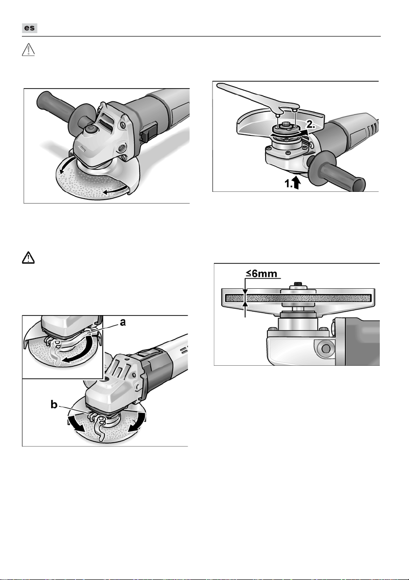
L 3709 -115, L 3709 -125, LE 9-10 125, L 10-10 125, L 801, L 1001
¡Peligro de lesiones!
¡CUIDADO!
Usar guantes de protección.
Desconectar el enchufe de red.
Girar la cubierta de protección de seguri-
dad hasta lograr la posición requerida.
Cubierta de montaje rápido
(LE 9-10 125, L 10-10 125, L 1001)
¡ADVERTENCIA!
Nunca trabajar sin la cubierta de protección
durante tareas de desbastado o tronzado.
Desconectar el enchufe de red.
Aflojar la palanca de montaje (a).
Ajustar la cubierta.
Sujeción o cambio de la herramienta amoladora
Desconectar el enchufe de red.
Presionar la traba del husillo y sostenerla
en esta posición (1.).
Aflojar la tuerca de montaje del husillo,
mediante la llave de pivotes, girando en
sentido antihorario (2.).
Colocar el disco amolador en la posición
correcta.
Ajustar el tornillo (b) con una fuerza tal,
que la palanca de ajuste solo pueda
ajustarse con fuerza.
Volver a ajustar la palanca de montaje.
Para el tronzado debe utilizarse una
cubierta de protección para tronzado
especial de montaje rápido.
54
Enroscar la tuerca de montaje (1b) con
el collarín hacia arriba en el husillo.
Presionar la traba del husillo (5) y
sostenerla presionada.
Ajustar la tuerca de montaje con la llave
de pivotes.
Conectar el enchufe de red.
Poner en marcha la amoladora angular
(sin traba) y dejarla en marcha durante
aprox. 30 segundos. Controlar si existen
excentricidades o vibraciones.
Parar la amoladora angular.
Page 55
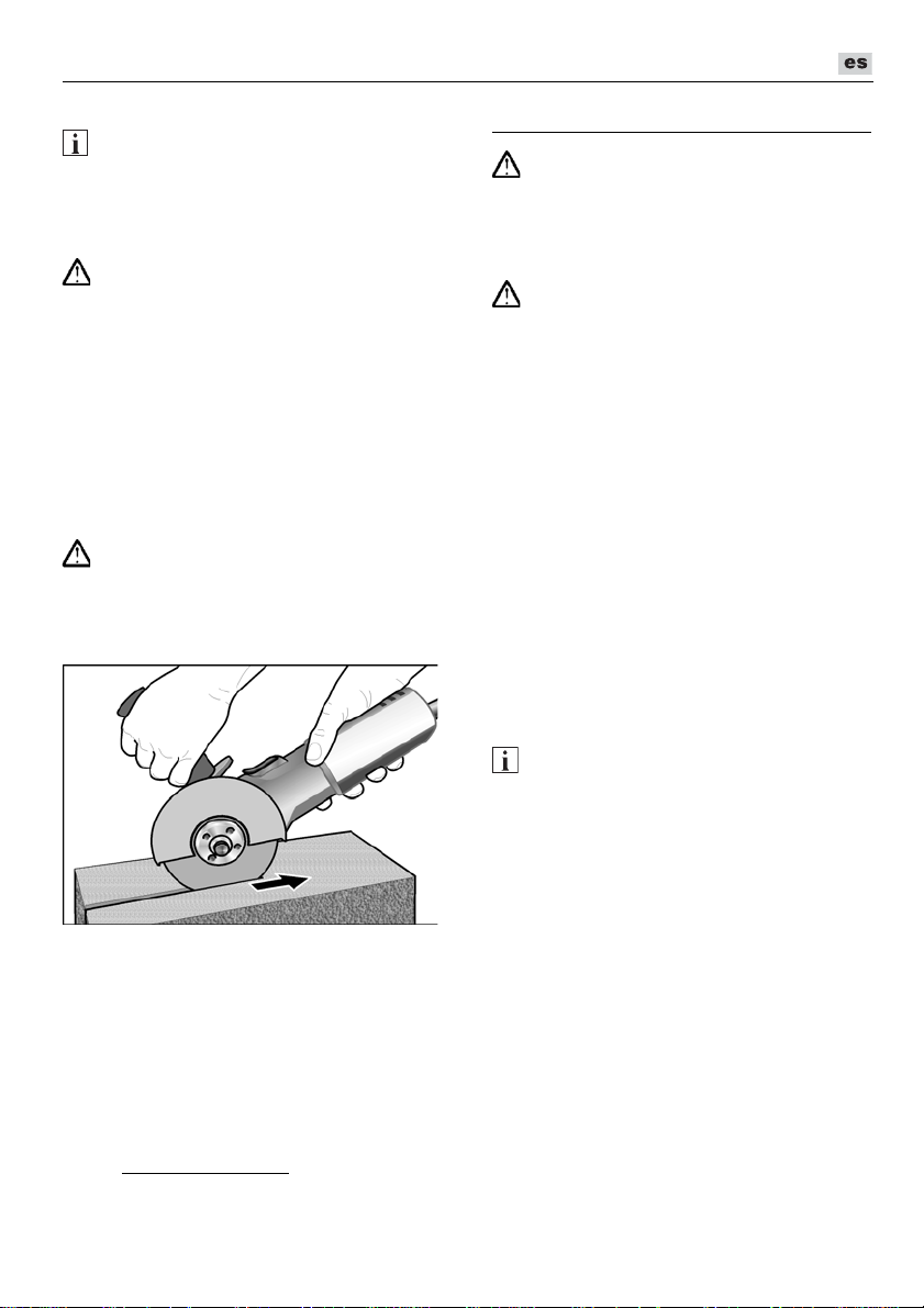
L 3709 -115, L 3709 -125, LE 9-10 125, L 10-10 125, L 801, L 1001
Indicaciones para el trabajo
Una vez apagada, la herramienta
amoladora presenta una breve marcha
inercial.
Amolado y desbastado
Nunca utilizar los discos para el tronzado,
para efectuar trabajos de desbastado.
– Para el mejor desbastado, se aconseja
– Efectuar un movimiento de vaivén,
Amolado y tronzado
Para el amolado/tronzado debe utilizarse
una cubierta de protección para tronzado
especial.
– No presionar, no ladear, no oscilar.
– La amoladora angular debe trabajar
– Adaptar la fuerza de avance al material
Obtendrá más informaciones sobre el producto por parte del fabricante, visitando
el sitio www.flex-tools.com
NOTA
¡ADVERTENCIA!
un ángulo de incidencia de 20° a 40°.
aplicando una presión moderada.
De esta modo la pieza en proceso no
se calienta demasiado y no se producen
cambios en el color de la misma.
Aparte se evita la formación de ranuras.
¡ADVERTENCIA!
siempre en contramarcha.
De lo contrario se corre el riesgo que
salte incontroladamente de la ranura de
corte.
en proceso: mientras mas duro, más
lento el avance.
.
Mantenimiento y cuidado
¡ADVERTENCIA!
Antes de realizar cualquier trabajo
en la amoladora, desconectar el enchufe
de red.
Limpieza
¡ADVERTENCIA!
Cuando se procesan metales, puede depositarse polvo conductor en el interior
de la carcasa. ¡Influencias sobre el
aislamiento de protección! Hacer funcionar
la máquina a través de un disyuntor
diferencial (corriente de accionamiento
máxima de 30 mA).
Limpiar regularmente el equipo y las ranuras
de ventilación. La frecuencia de la limpieza
dependerá del material y la intensidad de
uso.
Limpiar periódicamente la parte interior de la
carcasa y el motor con aire comprimido seco.
Escobillas de carbón
La amoladora angular está equipada con
escobillas de corte automático.
Cuando éstas llegan al límite de su
desgaste, la amoladora angular se detiene
automáticamente.
NOTA
Utilizar únicamente repuestos legítimos del
fabricante. En caso de uso de productos
de terceros, expira la garantía del
fabricante.
A través de las ranuras de ventilación posteriores, puede observarse el chispeo de las
escobillas durante el funcionamiento.
Si se observa un chispeo muy pronunciado,
deberá pararse inmediatamente la amoladora
angular. Entregar la amoladora a un taller de
servicio a clientes autorizado por el fabricante.
55
Page 56

L 3709 -115, L 3709 -125, LE 9-10 125, L 10-10 125, L 801, L 1001
Klaus Peter Weinper
Head of Quality
Department (QD)
Eckhard Rhle
Manager Research &
Development (R & D)
Engranaje
NOTA
No aflojar los tornillos en la cabeza del
engranaje durante el período de garantía.
El incumplimiento conduce a que la
garantía del fabricante caduque.
Reparaciones
Hacer efectuar las reparaciones exclusivamente por un taller de servicios a clientes
autorizado por el fabricante.
Repuestos y accesorios
Por otros accesorios, especialmente herramientas amoladoras y cubiertas de
protección para tronzadoras, rogamos
consultar los catálogos del fabricante.
Una gráfica de expansión y una lista de
piezas de repuesto se encuentran en la
homepage:
www.flex-tools.com
Indicaciones para la depolución
¡ADVERTENCIA!
Inutilizar equipos radiados, cortando el
cable de alimentación.
Unicamente para países pertenecientes a la CE
¡No arroje herramientas eléctricas
en los residuos domiciliarios!
Según la pauta europea 2012/19/UE y su
implementación a través de leyes nacio-
nales, los equipos eléctricos o electrónicos
en desuso deben coleccionarse por
separado, haciéndoselos llegar a un
reciclado que proteja el medio ambiente.
NOTA
¡Hágase informar por su comerciante
especializado respecto de las posibilidades
de eliminación!
Conformidad
Declaramos bajo nuestra única responsabilidad, que el producto descrito bajo
«Datos técnicos» coincide con las siguientes
normas y documentos normativos:
EN 60745 según las determinaciones
de la pauta 2014/30/UE, 2006/42/CE,
2011/65/UE
Responsable de la documentación técnica:
FLEX-Elektrowerkzeuge GmbH, R & D
Bahnhofstrasse 15, D-71711 Steinheim/Murr
16/06/2016; FLEX-Elektrowerkzeuge GmbH
Bahnhofstrasse 15, D-71711 Steinheim/Murr
.
Exclusión de la garantía
El fabricante y su representante no asumen
responsabilidad alguna por daños o pérdidas
de ganancia causados a la interrupción del
funcionamiento de la empresa, debidos al
producto o la no utilización del mismo.
El fabricante y su representante no asumen
responsabilidad alguna por daños causados
por el uso indebido o la utilización en
combinación con productos de otros
fabricantes.
56
Page 57
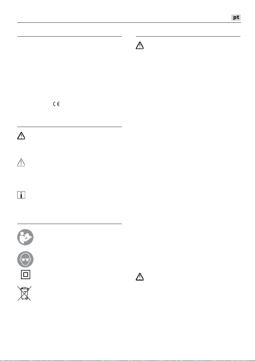
L 3709 -115, L 3709 -125, LE 9-10 125, L 10-10 125, L 801, L 1001
Índice
Símbolos utilizados . . . . . . . . . . . . . . . . 57
Símbolos no aparelho . . . . . . . . . . . . . . 57
Para sua segurança . . . . . . . . . . . . . . . 57
Ruído e vibração . . . . . . . . . . . . . . . . . . 61
Características técnicas . . . . . . . . . . . . 62
Panorâmica da máquina . . . . . . . . . . . . 63
Instruções de utilização . . . . . . . . . . . . . 64
Manutenção e tratamento . . . . . . . . . . . 66
Indicações sobre reciclagem . . . . . . . . . 67
Conformidade . . . . . . . . . . . . . . . . . 67
Exclusão de responsabilidades . . . . . . . 67
Símbolos utilizados
AVISO!
Caracteriza um perigo imediato e eminente.
A não observação da indicação, pode
implicar morte ou ferimentos muito graves.
ATENÇÃO!
Caracteriza uma situação possivelmente
perigosa. A não observação da indicação,
pode implicar ferimentos ou prejuízos
materiais.
INDICAÇÃO
Caracteriza conselhos para utilização
e informações importantes.
Símbolos no aparelho
Antes da colocação em funcionamento, leia as Instruções
de serviço!
Usar óculos de protecção!
Classe de protecção II
(completamente isolado)
Indicações sobre reciclagem para
o aparelho antigo (ver a pág. 67)!
Para sua segurança
AVISO!
Antes da utilização da rebarbadora, ler:
–
estas Instruções de serviço,
–
as instruções gerais de segurança, para
utilização com ferramentas eléctricas na
documentação anexa (Textos n.: 315.915),
–
as regras e as normas em vigor para
prevenção contra acidentes no local
de utilização.
Esta rebarbadora foi construída de acordo com
o estado actual da técnica e as regras técnicas
de segurança reconhecidas.
No entanto, na sua utilização, podem existir
danos para o utilizador ou terceiros, ou danos
na máquina ou noutros bens.
A rebarbadora só deve ser utilizada
–
de acordo com as disposições legais,
–
em perfeita situação de segurança técnica.
As anomalias que prejudiquem a segurança
devem ser imediatamente eliminadas
Utilização de acordo com
as disposições legais
Esta rebarbadora foi concebida
– para utilização profissional na indústria
e artesanato,
– para desbastar e cortar metais e pedras
em corte a seco; para cortar, é necessária uma capa especial de protecção de
corte,
– para aplicação com ferramenta de polir
e acessório que seja indicado nestas
instruções ou que seja recomendado
pelo fabricante e homologado para
uma velocidade periférica de 80 m/s.
Não são autorizados, p. ex. discos de fresar
de corrente, folhas de serra.
Indicações sobre segurança
AVISO!
Leia todas as indicações de segurança,
instruções, figuras e especificações
fornecidas com a ferramenta elétrica.
Negligências no respeito pelas indicações de
segurança podem ter como consequência um
choque eléctrico, incêndio e/ou ferimentos
graves. Guarde todas as indicações de
segurança e instruções para o futuro.
.
57
Page 58

L 3709 -115, L 3709 -125, LE 9-10 125, L 10-10 125, L 801, L 1001
Advertências gerais de segurança para
lixar normal e rectificar
Esta ferramenta eléctrica deve ser
utilizada como lixadora e como máquina
rectificadora. Respeitar todas as indicações de segurança, instruções, apresentações e dados fornecidos juntamente
com o aparelho.
Se as instruções seguintes não forem
respeitadas, podem ser surgir choques
eléctricos, incêndios e/ou ferimentos
graves.
Esta ferramenta eléctrica não é própria
para lixar com lixa de papel, para trabalhar
com escovas de arame e para polir.
Utilizações para as quais a ferramenta
eléctrica não está prevista podem
provocar perigos e ferimentos
Não utilizar qualquer acessório que
não tenha sido previsto e recomendado
especialmente pelo fabricante para esta
ferramenta eléctrica.
Só porque foi possível fixar o acessório
na sua ferramenta eléctrica, isso não
garante uma utilização com segurança.
A rotação permitida para a ferramenta
de utilização tem, no mínimo, que ser
tão elevada como a rotação máxima
indicada na própria ferramenta eléctrica.
Um acessório que gire com uma rotação
superior à recomendada pode partir-se
e ser projectado em várias direcções.
Diâmetro exterior e espessura da ferra-
menta de utilização têm que corresponder às indicações de medidas
referidas na ferramenta eléctrica.
Ferramentas mal dimensionadas podem
não ser suficientemente protegidas
ou controladas.
Ferramentas de trabalho com encaixe
roscado devem caber exactamente na
rosca do veio de rectificação. Para ferramentas de trabalho montadas com flange
é necessário que o diâmetro do furo da
ferramenta de trabalho tenha as dimensões apropriadas para o flange.
Ferramentas de trabalho, que não são
fixas exactamente na ferramenta eléctrica,
giram de forma irregular, vibram fortemente e podem levar à perda de controlo.
.
Nunca usar ferramenta danificadas. Antes
de cada utilização deverá controlar as
ferramentas de trabalho, e verificar se por
exemplo os discos abrasivos apresentam
fissuras e estilhaços, se pratos abrasivos
apresentam fissuras, se há desgaste ou
forte atrição, se as escovas de arame
apresentam arames soltos ou quebrados.
Se a ferramenta eléctrica ou a ferramenta
de adaptação sofrer uma queda, verificar
se alguma delas apresenta danos ou
utilizar outra ferramenta livre de danos.
Depois de ter sido controlada e aplicada a
ferramenta, o operador e, eventualmente,
outras pessoas, devem manter-se fora da
área da ferramenta em rotação e deixar o
aparelho funcionar com a rotação máxima
durante um minuto.
As ferramentas
danificadas partem-se na maioria das
vezes durante este tempo de teste.
Utilizar equipamento de segurança
pessoal. De acordo com a utilização
usar protecção total da face, protecção
para os olhos e óculos de protecção.
Se for considerado conveniente, utilizar
máscara para o pó, protecção para os
ouvidos, luvas de protecção ou aventais
especiais que mantém afastadas pequenas partículas de lixa e de material.
Os olhos devem estar protegidos contra
corpos estranhos projectados, o que
pode acontecer em diversas situações
de utilização do aparelho.
Máscaras para o pó e de respiração
têm que filtrar o pó provocado durante
a utilização. Se o operador estiver sujeito
a ruído intenso e prolongado, pode sofrer
danos de audição.
Tomar atenção relativamente a uma
distância de segurança entre outras
pessoas e o seu local de trabalho.
Qualquer pessoa que entre na zona
de trabalho tem que usar equipamento
de protecção pessoal.
Pedaços de material da obra ou
ferramentas partidas podem ser
projectados e provocar ferimentos,
mesmo distanciados do local de trabalho
directo.
58
Page 59

L 3709 -115, L 3709 -125, LE 9-10 125, L 10-10 125, L 801, L 1001
Segurar o aparelho somente pelas
superfícies de manipulação isoladas,
quando se executam trabalhos, nos
quais a ferramenta pode encontrar cabos
eléctricos ocultos ou o próprio cabo
de alimentação de corrente.
O contacto com um cabo sob tensão
pode também colocar componentes
metálicos do aparelho sob tensão
e provocar um choque eléctrico.
Manter o cabo de rede afastado de ferra-
mentas em rotação.
Se o operador perder o controlo do aparelho, o cabo de rede pode ser cortado
ou colhido e a mão ou o braço do operador podem ser atingidos pela ferramenta
em rotação.
Nunca pousar o aparelho antes da ferra-
menta estar completamente parada.
A ferramenta em rotação pode entrar em
contacto com a superfície de assento,
o que pode provocar a perda de controlo
do aparelho.
Não deixar a ferramenta eléctrica funcio-
nar enquanto esta é transportada.
O vestuário do operador pode, por
contacto ocasional, ser captado pela
ferramenta em rotação e provocar-lhe
ferimentos graves.
Limpar regularmente as ranhuras
de ventilação da ferramenta eléctrica.
A turbina do motor aspira pó para
o interior do aparelho e uma forte
acumulação de pó com teor de metal
pode provocar perigo de choque
eléctrico.
Não utilizar a ferramenta eléctrica nas
proximidades de materiais inflamáveis.
Faíscas podem inflamar estes materiais.
Não utilizar ferramentas que exijam
agentes de refrigeração líquidos.
A utilização de água ou outros agentes
de refrigeração líquidos pode provocar
choques eléctricos.
Contragolpe e instruções de segurança
correspondentes
Contragolpe é a reacção repentina em
consequência de uma prisão ou bloqueio de
uma ferramenta em rotação, como discos
de lixar, pratos de lixar, escovas de arame
etc. Prisão ou bloqueio dá origem a uma
paragem abrupta da ferramenta
em rotação. Devido a isso, uma ferramenta
eléctrica descontrolada é acelerada,
no ponto de bloqueio, contra o sentido
de rotação da ferramenta de utilização.
Se, p. ex., um disco de lixar prender
ou bloquear na peça em processamento,
significa que a aresta do disco de lixar que
penetra na peça pode encravar e, devido
a isso, o disco de lixar partir ou provocar
um contragolpe.
O disco de lixar movimenta-se, então,
na direcção do operador ou afastando-se
deste, dependente do sentido de rotação
no ponto de bloqueio. Devido a isso, os
discos de lixar podem também partir-se.
Um contragolpe é a consequência
de uma utilização errada ou defeituosa
da ferramenta eléctrica. Ele pode ser
evitado através de medidas de precaução
adequadas, conforme descrito a seguir.
Manter a ferramenta eléctrica bem presa
e colocar o corpo e os braços numa posição, em que as forças do contragolpe
possam ser suportadas. Utilizar sempre
o punho adicional, caso esteja disponível, para ter o máximo controlo possível sobre as forças do contragolpe ou
momentos de reacção no funcionamento
do aparelho em rotação elevada.
O operador pode dominar as forças
de contragolpe e de reacção com
medidas de precaução adequadas.
Nunca colocar as mãos na proximidade
de ferramentas em rotação.
A ferramenta em utilização pode movimentar-se contra as mãos do operador
em caso de contragolpe.
Evite, com o seu corpo, o espaço onde
a ferramenta eléctrica é movimentada
no caso dum contragolpe.
O contragolpe movimenta a ferramenta
eléctrica no sentido contrário ao movimento do disco de lixar no ponto
de bloqueio.
59
Page 60

L 3709 -115, L 3709 -125, LE 9-10 125, L 10-10 125, L 801, L 1001
Trabalhar com precaução redobrada
em esquinas, cantos aguçados etc.
Evitar que ferramentas de utilização
ressaltem da peça a trabalhar
eseencravem.
A ferramenta em rotação tem tendência
para encravar em cantos, arestas
aguçadas ou se fizer ricochete.
Isto provoca uma perda de controlo
ou um contragolpe.
Não utilizar lâminas de serra de corrente
ou de dentes.
As ferramentas deste tipo provocam
frequentemente um contragolpe
ou a perda de controlo sobre a ferramenta eléctrica.
Instruções especiais de segurança
para lixar e para rectificar
Utilizar exclusivamente os rebolos
de lixar homologados para a sua ferramenta eléctrica e a tampa de protecção
prevista para este rebolo de lixar.
Rebolos de lixar não previstos para esta
ferramenta eléctrica podem não estar
suficientemente protegidos e não são
seguros.
Rebolos acotovelados devem ser
montados de modo que a sua superfície
rectificadora não sobressaia do nível da
borda da cobertura de protecção.
Um rebolo montado de forma incorrecta,
que sobressai do nível da borda da
cobertura de protecção, não pode ser
suficientemente protegido.
A tampa de protecção deve ser firme-
mente aplicada na ferramenta eléctrica
e fixa, de modo que seja alcançado um
máximo de segurança, ou seja, que
apenas uma mínima parte do rebolo
aponte abertamente na direcção do
operador.
A tampa de protecção ajuda a proteger
a pessoa, que está a operar a máquina,
contra estilhaços, contacto acidental com
o rebolo, e contra faíscas que possam
incendiar as roupas.
Os rebolos de lixar só podem ser utiliza-
dos nas possibilidades de aplicação
recomendadas. Por exemplo: Nunca
lixar com a superfície lateral de um disco
de corte.
Os discos de corte estão preparados
para cortar o material com a aresta
do disco. Um efeito de força lateral
sobre este rebolo de lixar pode parti-lo.
Utilizar sempre flanges de aperto intac-
tos, com o tamanho e a forma correctos,
para o disco de lixar por si seleccionado.
Flanges adequados apoiam o disco de
lixar e, por isso, reduzem o perigo da sua
ruptura. Os flanges para discos de corte
podem ser diferentes dos flanges para
outros discos de lixar.
Nunca utilizar discos de lixar desgasta-
dos de ferramentas eléctricas maiores.
Os discos de lixar para ferramentas eléctricas maiores não estão preparados
para as rotações mais elevadas de ferramentas eléctricas mais pequenas
e podem quebrar.
Outras i
nstruções especiais de
segurança para rectificar
Evitar o bloqueio do disco de corte
ou uma pressão de encosto demasiado
elevada. Não executar cortes demasiado
profundos.
Uma sobrecarga do disco de corte
aumenta o esforço a que este está
sujeito e a sua tendência para encravar
ou bloquear e, assim, a possibilidade
de um contragolpe ou o quebrar
do corpo de corte.
Evitar a zona circundante ao disco
de corte em rotação.
Se o disco de corte se afastar da peça
a trabalhar, pode acontecer que, no caso
de um contragolpe, a ferramenta eléctrica, com o disco em rotação, se lance
directamente contra si.
Se o disco de corte encravar ou V.
interromper o trabalho, deverá desligar
o aparelho e segurá-lo calmamente
até que o disco pare completamente.
Nunca tentar retirar do corte o disco
de corte em rotação, pois pode surgir
um contragolpe. Verificar e eliminar
a causa do disco encravar.
60
Page 61

L 3709 -115, L 3709 -125, LE 9-10 125, L 10-10 125, L 801, L 1001
Não voltar a ligar a ferramenta eléctrica,
enquanto ela se encontrar inserida na
peça. Deixar o disco de corte atingir
a rotação máxima e só depois prosseguir
com o corte.
Caso contrário, o disco pode encravar,
saltar para fora da ferramenta ou provocar um contragolpe.
Seja particularmente prudente ao execu-
tar «cortes de bolso» em paredes
já existentes ou noutras zonas não
reconhecíveis.
O disco de corte penetrante, ao cortar
canalizações para gás e água, cabos
eléctricos ou outros objectos, pode
provocar um contragolpe.
Apoiar as placas ou as grandes
peças a trabalhar, para reduzir o risco
de um contragolpe, devido ao disco
de corte entalado.
Peças grandes podem curvar sob o seu
próprio peso. A peça a trabalhar deve
estar apoiada de ambos os lados, quer
na proximidade do corte quer também
junto à aresta.
Outras instruções de segurança
A tensão da rede e a indicação
de tensão na chapa de características têm que ser coincidentes.
O bloqueio do veio só deve ser activado
com a ferramenta abrasiva
completamente parada.
Ruído e vibração
INDICAÇÃO
Consultar os valores do nível de ruído avaliado com A e os valores totais das vibrações na tabela «Características técnicas».
Os valores de ruído e de vibração foram
apurados de acordo com a EN 60745.
ATENÇÃO!
Os valores de medição indicados são
válidos para aparelhos novos.
Na utilização diária alteram-se os valores
de ruído e de oscilação.
O nível de vibrações indicado nestas instruções foi medido em conformidade com
um processo de medição normalizado
na EN 60745 e pode ser utilizado para
a comparação de ferramentas eléctricas
entre si. Este processo também é adequado
para uma estimativa provisória da carga
das vibrações.
O nível de vibrações indicado representa
as principais utilizações das ferramentas
eléctricas. Se, no entanto, a ferramenta
eléctrica for aplicada noutras situações com
ferramentas diferentes ou com insuficiente
manutenção, o nível de vibrações também
pode ser diferente. Isto pode aumentar
claramente a carga das vibrações durante
o período global de trabalho.
Para uma estimativa exacta da carga das
vibrações, devem, também, ser considerados os tempos, durante os quais o aparelho
está desligado ou, embora estando a funcionar, não está, de facto, em utilização.
Isto pode reduzir claramente a carga
das vibrações durante o período global
de trabalho.
Determinar medidas de segurança adicionais para protecção do utilizador do efeito
das vibrações, como, por exemplo:
Manutenção da ferramenta eléctrica
e das ferramentas aplicadas, manutenção
das mãos quentes, organização dos ciclos
de trabalho
.
ATENÇÃO!
Com um nível de pressão acústica superior
a 85 dB(A), deve ser usado um protector
para os ouvidos.
INDICAÇÃO
61
Page 62

L 3709 -115, L 3709 -125, LE 9-10 125, L 10-10 125, L 801, L 1001
Características técnicas
L 3709-115 L 3709-125
L 801
LE 9-10 125 L 10-10 125
L 1001
Tipo do aparelho Rebarbadora
Ø máx. da ferramenta abrasiva
Espessura da ferramenta
abrasiva
Furo do porta ferramentas
Rosca do veio
Rotações
Potência absorvida
Potência útil
mm 115 125 125 125
mm 1–6
mm 22,23
M14
rpm 12500
12000
6000–11500 10000
W 750 800 900 1010
W 450 480 530 600
Peso de acordo com „EPTA
Procedure 01/2003“ (sem
kg 1,9 2,0 2,2
cabo)
Classe de protecção
II/
Nível de ruído avaliado com A de acordo com a EN 60745 (ver «Ruído e vibração»):
Nível de pressão acústica L
Nível de potência acústica L
Insegurança K
pA
WA
dB(A)
dB(A)
db
84,6 87 91
95,6 98 102
3
Valor total das vibrações conforme a EN 60745 (ver «Ruído e vibração»):
Valor de emissão a
superfícies
Valor de emissão ah durante
a operação de corte
Insegurança K
ao lixar
h
m/s
m/s
m/s
2
2
2
6,5 6,5 6,6
6,3 8,1 6,2
1,5
62
Page 63

L 3709 -115, L 3709 -125, LE 9-10 125, L 10-10 125, L 801, L 1001
Panorâmica da máquina
Neste manual são descritas várias ferramentas eléctricas. As representações gráficas podem
divergir da ferramenta eléctrica adquirida no que diz respeito a detalhes.
1 Veio roscado
2 Flange roscada
a Porca de aperto
b Flange de aperto
3 Capa de protecção
4 Punho
Punho com montagem possível
à esquerda e à direita.
5 Bloqueio do veio
Para fixação do veio na mudança
da ferramenta.
6 Cabeça de engrenagem
Com saída de ar e seta indicadora
do sentido das rotações.
7 Interruptor basculante
Para ligar e desligar a máquina.
Com posição de encaixe para
funcionamento contínuo.
8 Cabo de rede com 4,0 m e com ficha
de ligação à rede.
9 Chave de boca com pinos
10 Chapa de características
(não é apresentado)
11 Volante de ajuste para prévia selecção
das rotações (só para LE 9-10 125)
63
Page 64
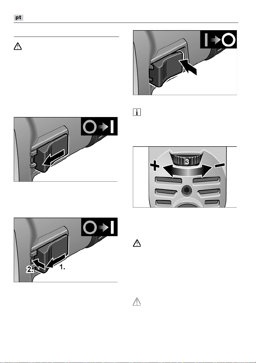
L 3709 -115, L 3709 -125, LE 9-10 125, L 10-10 125, L 801, L 1001
Instruções de utilização
Antes de quaisquer trabalhos na rebarba-
AVISO!
dora, desligue a ficha da tomada.
Antes da colocação em funcionamento
Desembalar a rebarbadora e verificar,
se o fornecimento está completo e não
existem danos de transporte.
Ligar e desligar
Funcionamento curta sem engate:
Deslocar o interruptor basculante
para a frente e prendê-lo.
Para desligar, libertar o interruptor
basculante.
Funcionamento contínuo com engate:
Deslocar o interruptor basculante para
a frente e engatá-lo (1.), exercendo
pressão na parte da frente (2.).
Para desligar, exercer pressão na parte
de trás do interruptor.
INDICAÇÃO
Depois duma falta de corrente, o aparelho
ligado não volta a arrancar.
Selecção prévia da rotação
(só para LE 9-10 125)
Para regular as rotações de serviço, colocar
o volante de ajuste no valor desejado.
Capa de protecção de segurança
(L 3709-115, L 801, L 3709-125)
AVISO!
Nunca trabalhar sem a capa de protecção
e segurança de corte.
Para adaptação ao trabalho a executar,
a tampa de protecção de segurança
é ajustável sem necessidade de
ferramentas.
Para cortar, deve ser utilizada uma capa
especial de protecção de corte.
ATENÇÃO!
Perigo de ferimentos!
Utilizar luvas de protecção.
Desligar a ficha da tomada.
64
Page 65
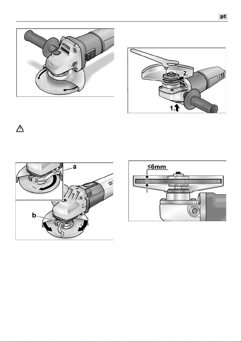
L 3709 -115, L 3709 -125, LE 9-10 125, L 10-10 125, L 801, L 1001
Fixar ou substituir a ferramenta
de lixar
Desligar a ficha da tomada.
Rodar a tampa de protecção de
segurança até à posição necessária.
Resguardo de fixação rápida
(LE 9-10 125, L 10-10 125, L 1001)
AVISO!
Nos trabalhos de desbastar e de cortar,
utilizar sempre a capa de protecção.
Desligar a ficha da tomada.
Desapertar a alavanca de fixação (a).
Ajustar o resguardo de protecção.
Premir e manter premido o bloqueio
do veio (1.).
Com a chave de boca com pinos,
desmontar a porca de fixação do veio
rodando-a em sentido contrário ao dos
ponteiros do relógio (2.).
Colocar a ferramenta abrasiva na
posição correcta.
Apertar o parafuso (b) de modo que
ainda seja possível apertar
manualmente a alavanca de aperto.
Voltar a apertar a alavanca de fixação.
Para cortar, deve ser utilizada uma capa
especial de protecção de corte de aperto
rápido.
Apertar a porca de fixação no veio,
com o colar para cima.
Premir e manter premido o bloqueio
do veio.
Apertar a porca de aperto com a chave
de boca com pinos.
Encaixar a ficha de rede na tomada.
Ligar a rebarbadora com interruptor
basculante, (sem o encaixar) e colocar
a rebarbadora em funcionamento,
durante ca. de 30 segundos.
Verificar, se existem desequilíbrios
ou vibrações.
Desligar a rebarbadora.
65
Page 66
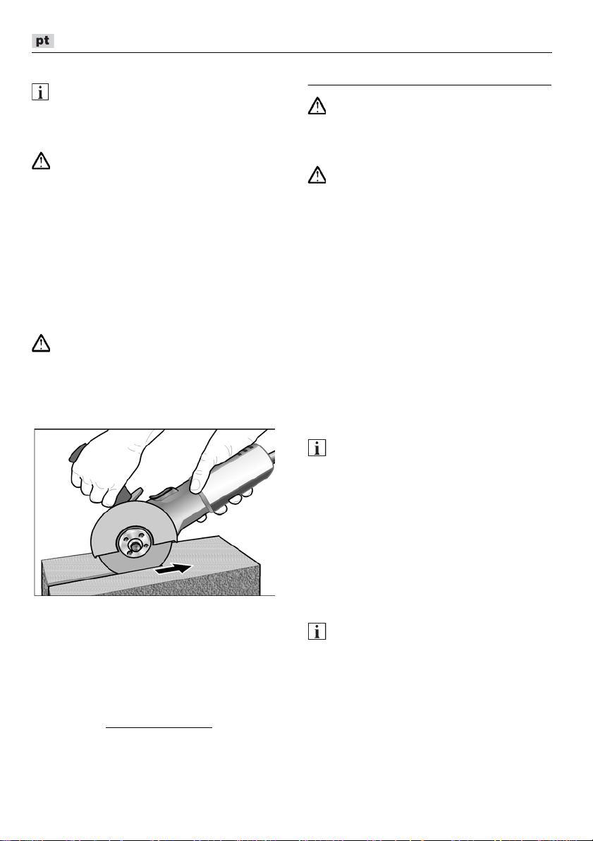
L 3709 -115, L 3709 -125, LE 9-10 125, L 10-10 125, L 801, L 1001
Indicações sobre trabalho
Depois de desligada, a ferramenta eléctrica
ainda roda durante breves momentos.
Desbastar
Nunca utilizar um disco de corte para
efectuar trabalhos de desbaste.
– Ângulo de ataque 20°–40º para um
– Deslocar a rebarbadora, para lá e para
Trabalhos de cortar
Para um corte de separação tem que
ser utilizada uma tampa de protecção
especial.
– Não pressionar, não emperrar, não
– A rebarbadora tem que funcionar,
– Adaptar o avanço ao material que se
Mais informações sobre os produtos do fabricante no site www.flex-tools.com
INDICAÇÃO
AVISO!
trabalho de desbaste em melhores
condições.
cá, com uma pressão moderada.
Assim, a peça não aquece muito e não
se verificam descolorações; além disso
não se formam estrias.
AVISO!
oscilar.
sempre, em sentido contrário.
Caso contrário, existe perigo de salto
descontrolado para fora da ranhura.
está a trabalhar: quanto mais duro, mais
lento.
.
Manutenção e tratamento
AVISO!
Antes de quaisquer trabalhos na rebarbadora, desligue a ficha da tomada.
Limpeza
AVISO!
Ao trabalhar-se com metais e em caso
de utilização extrema, pode depositar-se
pó condutivo no interior da estrutura. Danos no
isolamento de protecção! A máquina deve
funcionar através dum interruptor de protecção
contra corrente de falha (corrente de activação
máxima 30 mA).
Limpar regularmente o aparelho e as ranhuras de ventilação. A frequência da limpeza
depende do material a trabalhar e da duração da utilização.
Limpar, regularmente, com ar comprimido
seco, o interior da estrutura com motor.
Escovas de carvão
A rebarbadora está equipada com carvões
de corte de ligação.A atingir-se o limite
de desgaste dos carvões, a rebarbadora
desliga automaticamente.
INDICAÇÃO
Na substituição, utilizar somente peças
originais do fabricante. Sendo utilizadas
peças de outros fabricantes, expiram
as obrigações de garantia do fabricante.
Através das entradas de ar traseiras, podese observar a ignição dos carvões, durante
o funcionamento. Caso a chama das escovas seja muito forte, desligar imediatamente
a rebarbadora. Entregar a rebarbadora num
Posto Oficial de Assistência Técnica.
Engrenagem
INDICAÇÃO
Não desapertar os parafusos da cabeça
de engrenagem. Se esta indicação não
for respeitada, expiram as obrigações
de garantia do fabricante.
66
Page 67

L 3709 -115, L 3709 -125, LE 9-10 125, L 10-10 125, L 801, L 1001
Klaus Peter Weinper
Head of Quality
Department (QD)
Eckhard Rhle
Manager Research &
Development (R & D)
Reparações
As reparações devem ser executadas,
exclusivamente, por Serviços Técnicos
autorizados pelo fabricante.
Peças de reparação e acessórios
Para mais acessórios, principalmente ferramentas abrasivas, consulte o catálogo
do fabricante.
Desenhos de explosão e listas de peças
de reparação podem ser consultados
na nossa Homepage:
www.flex-tools.com
Indicações sobre reciclagem
AVISO!
Os aparelhos fora de serviço devem
ser inutilizados, retirando-lhes os cabos
de ligação à rede.
Só para os países da UE
Não colocar as ferramentas
eléctricas no lixo doméstico!
Em conformidade com a Directiva
Europeia 2012/19/UE sobre aparelhos
eléctricos e electrónicos usados e com
a transposição para o Direito Nacional,
as ferramentas eléctricas usadas têm que
ser reunidas separadamente e encaminhadas para o reaproveitamento sem
poluição do meio ambiente.
INDICAÇÃO
Informe-se sobre possibilidades de reciclagem junto do agente especializado!
Conformidade
Declaramos, sob nossa inteira responsabilidade, que o produto descrito em
«Características técnicas» se encontra em
conformidade com as normas e os documentos normativos seguintes:
EN 60745 de acordo com as determinações das directivas 2014/30/UE,
2006/42/CE, 2011/65/UE.
Responsável pela documentação técnica:
FLEX-Elektrowerkzeuge GmbH, R & D
Bahnhofstrasse 15, D-71711 Steinheim/Murr
16/06/2016; FLEX-Elektrowerkzeuge GmbH
Bahnhofstrasse 15, D-71711 Steinheim/Murr
Exclusão de responsabilidades
O fabricante e seus representantes não
se responsabilizam por danos e perda de
lucros, resultantes da interrupção do
negócio, provocada pelo produto ou pela
possível não utilização do mesmo.
O fabricante e seus representantes não se
responsabilizam por danos provocados por
uma utilização inadequada ou em ligação
com produtos de outros fabricantes.
67
Page 68
L 3709 -115, L 3709 -125, LE 9-10 125, L 10-10 125, L 801, L 1001
Inhoud
Gebruikte symbolen . . . . . . . . . . . . . . . 68
Symbolen op het gereedschap . . . . . . . 68
Voor uw veiligheid . . . . . . . . . . . . . . . . . 68
Geluid en trillingen . . . . . . . . . . . . . . . . . 72
Technische gegevens . . . . . . . . . . . . . . 73
In één oogopslag . . . . . . . . . . . . . . . . . . 74
Gebruiksaanwijzing . . . . . . . . . . . . . . . . 75
Onderhoud en verzorging . . . . . . . . . . . 77
Afvoeren van verpakking en machine . . 78
-Conformiteit . . . . . . . . . . . . . . . . . . . 78
Uitsluiting van aansprakelijkheid . . . . . . 78
Gebruikte symbolen
WAARSCHUWING!
Geeft een onmiddellijk dreigend gevaar
aan. Als de waarschuwing niet in acht wordt
genomen, dreigen levensgevaarlijke of zeer
ernstige verwondingen.
VOORZICHTIG!
Geeft een mogelijk gevaarlijke situatie aan.
Als de aanwijzing niet in acht wordt
genomen, kunnen persoonlijk letsel of
materiële schade het gevolg zijn.
LET OP
Geeft gebruikstips en belangrijke informatie
aan.
Symbolen op het gereedschap
Lees de gebruiksaanwijzing
voordat u het gereedschap
in gebruik neemt!
Draag een oogbescherming!
Isolatieklasse II
(volledig geïsoleerd)
Afvoeren van het oude apparaat
(zie pagina 78)!
Voor uw veiligheid
WAARSCHUWING!
Lees voor het gebruik van de haakse
slijpmachine de volgende voorschriften
en neem deze in acht:
–
deze gebruiksaanwijzing,
–
de „Algemene veiligheidsvoorschriften”
voor het gebruik van elektrische gereedschappen in de meegeleverde brochure
(document-nummer: 315.915),
–
de op de plaats van gebruik geldende
regels en voorschriften ter voorkoming
van ongevallen.
Deze haakse slijpmachine is geconstrueerd
volgens de huidige stand van de techniek
en de erkende veiligheidstechnische regels.
Toch kunnen bij het gebruik ervan levensgevaar en verwondingsgevaar voor de
gebruiker en voor andere personen resp.
gevaren voor beschadigingen aan de machine
of aan andere zaken optreden. De haakse
slijpmachine mag alleen worden gebruikt:
–
volgens de bestemming,
–
in een veiligheidstechnisch optimale
toestand.
Verhelp storingen die de veiligheid in gevaar
brengen onmiddellijk
Gebruik volgens bestemming
Deze haakse slijpmachine is bestemd:
– voor professioneel gebruik in de industrie
en door de vakman,
– voor het droog slijpen en doorslijpen
van metaal en steen; voor doorslijpen is
een speciale doorslijpbeschermkap
vereist,
– voor gebruik met slijpgereedschap en
toebehoren dat in deze gebruiksaanwijzing aangegeven of door de fabrikant
wordt geadviseerd en voor een omtrek-
snelheid van 80 m/s is toegestaan.
Niet toegestaan zijn bijvoorbeeld kettingfreesschijven en zaagbladen.
.
68
Page 69

L 3709 -115, L 3709 -125, LE 9-10 125, L 10-10 125, L 801, L 1001
Veiligheidsvoorschriften
WAARSCHUWING!
Lees alle met het elektrisch gereedschap
meegeleverde veiligheidsvoorschriften,
aanwijzingen, afbeeldingen en specificaties.
Als de veiligheidsvoorschriften en aanwijzingen niet in acht worden genomen, kan dit
een elektrische schok, brand en/of ernstig
letsel tot gevolg hebben. Bewaar alle veiligheidsvoorschriften en aanwijzingen voor de
toekomst.
Algemene waarschuwingen voor
slijpen en doorslijpen
Dit elektrische gereedschap is te ge-
bruiken als slijp- en doorslijpmachine.
Neem alle veiligheidsvoorschriften, aanwijzingen, afbeeldingen en gegevens die
u bij het gereedschap ontvangt in acht.
Als u de volgende aanwijzingen niet
in acht neemt, kunnen een elektrische
schok, brand en/of ernstig letsel het
gevolg zijn.
Dit elektrische gereedschap is niet
geschikt voor schuurwerkzaamheden
(met schuurpapier), werkzaamheden met
draadborstels en polijstwerkzaamheden.
Toepassingen waarvoor het elektrische
gereedschap niet is voorzien, kunnen
gevaren en verwondingen veroorzaken
Gebruik uitsluitend toebehoren dat door
de fabrikant speciaal voor dit elektrische
gereedschap is voorzien en geadviseerd.
Het feit dat u het toebehoren aan het
elektrische gereedschap kunt bevestigen, waarborgt nog geen veilig gebruik.
Het toegestane toerental van het inzet-
gereedschap moet minstens even hoog
zijn als het maximale toerental dat op het
elektrische gereedschap vermeld staat.
Toebehoren dat sneller draait dan toegestaan, kan onherstelbaar beschadigd
worden en wegvliegen.
De buitendiameter en de dikte van het
inzetgereedschap moeten overeenkomen met de maatgegevens van het
elektrische gereedschap. Inzetgereed-
.
Inzetgereedschappen met schroefdraadinzetstuk moeten nauwkeurig op de
schroefdraad van de uitgaande as
passen. De gatdiameter van met een flens
gemonteerde inzetgereedschappen moet
passen bij de opnamediameter van de
flens.
Inzetgereedschappen die niet
nauwkeurig op de uitgaande as van het
elektrische gereedschap passen,
draaien ongelijkmatig, trillen sterk en
kunnen tot het verlies van de controle
leiden.
Gebruik geen beschadigde inzetgereed-
schappen. Controleer voor het gebruik
altijd inzetgereedschappen zoals
slijpschijven op afsplinteringen en
scheuren, steunschijven op scheuren of
sterke slijtage en draadborstels op losse
of gebroken draden. Als het elektrische
gereedschap of het inzetgereedschap
valt, dient u te controleren of het beschadigd is, of gebruik een onbeschadigd
inzetgereedschap. Als u het inzetgereedschap hebt gecontroleerd en ingezet,
laat u de machine een minuut lang met
het maximale toerental lopen.
Daarbij dient u en dienen andere personen uit de buurt van het ronddraaiende
inzetgereedschap te blijven.
Beschadigde inzetgereedschappen
breken meestal gedurende deze testtijd.
Draag persoonlijke beschermende uit-
rusting. Gebruik afhankelijk van de toepassing een volledige gezichtsbescherming, oogbescherming of veiligheidsbril.
Draag indien van toepassing een stofmasker, een gehoorbescherming,
werkhandschoenen of een speciaal
schort dat kleine slijp- en metaaldeeltjes
tegenhoudt.
Uw ogen moeten worden beschermd
tegen wegvliegende deeltjes die bij verschillende toepassingen ontstaan.
Een stof- of ademmasker moet het stof
filteren dat bij de toepassing ontstaat.
Als u lang wordt blootgesteld aan luid
lawaai, kan uw gehoor worden beschadigd.
schappen met onjuiste afmetingen
kunnen niet voldoende afgeschermd of
gecontroleerd worden.
69
Page 70

L 3709 -115, L 3709 -125, LE 9-10 125, L 10-10 125, L 801, L 1001
Let erop dat andere personen zich
op een veilige afstand bevinden van
de plaats waar u werkt. Iedereen
die de werkomgeving betreedt, moet
persoonlijke beschermende uitrusting
dragen.
Brokstukken van het werkstuk
of gebroken inzetgereedschappen
kunnen wegvliegen en verwondingen
veroorzaken, ook buiten de directe
werkomgeving.
Houd het gereedschap alleen aan
de geïsoleerde greepvlakken vast
als u werkzaamheden uitvoert waarbij
het inzetgereedschap verborgen stroomleidingen of de eigen stroomkabel kan
raken.
Contact met een onder spanning
staande leiding kan ook metalen delen
van het gereedschap onder spanning
zetten en tot een elektrische schok
leiden.
Houd de stroomkabel uit de buurt van
draaiende inzetgereedschappen.
Als u de controle over het gereedschap
verliest, kan de stroomkabel worden
doorgesneden of meegenomen en uw
hand of arm kan in het ronddraaiende
inzetgereedschap terechtkomen.
Leg het elektrische gereedschap nooit
neer voordat het inzetgereedschap
volledig tot stilstand is gekomen.
Het draaiende inzetgereedschap kan
in contact komen met het oppervlak,
waardoor u de controle over het elektrische gereedschap kunt verliezen.
Laat het elektrische gereedschap niet
lopen terwijl u het draagt.
Uw kleding kan door toevallig contact
met het draaiende inzetgereedschap
worden meegenomen en het inzetgereedschap kan zich in uw lichaam
boren.
Reinig regelmatig de ventilatieopeningen
van het elektrische gereedschap.
De motorventilator trekt stof in het huis
en een sterke ophoping van metaalstof
kan elektrische gevaren veroorzaken.
Gebruik het elektrische gereedschap niet
in de buurt van brandbare materialen.
Vonken kunnen deze materialen
ontsteken.
Gebruik geen inzetgereedschappen waarvoor vloeibare koelmiddelen vereist zijn.
Het gebruik van water of andere vloeibare koelmiddelen kan tot een elektrische schok leiden.
Terugslag en bijbehorende veiligheidsvoorschriften
Terugslag is de plotselinge reactie als
gevolg van een vasthakend of geblokkeerd
draaiend inzetgereedschap, zoals een
slijpschijf, schuurschijf, steunschijf, draadborstel, enz. Vasthaken of blokkeren leidt
tot een abrupte stop van het ronddraaiende
inzetgereedschap. Daardoor wordt een
ongecontroleerd elektrisch gereedschap
tegen de draairichting van het inzetgereedschap versneld op de plaats van de blokkering.
Als bijvoorbeeld een slijpschijf in het
werkstuk vasthaakt of blokkeert, kan de
rand van de slijpschijf die in het werkstuk
invalt, zich vastgrijpen. Daardoor kan
de slijpschijf uitbreken of een terugslag
veroorzaken. De slijpschijf beweegt zich
vervolgens naar de bediener toe of van
de bediener weg, afhankelijk van de draairichting van de schijf op de plaats van
de blokkering. Hierbij kunnen slijpschijven
ook breken.
Een terugslag is het gevolg van verkeerd of
onjuist gebruik van het elektrische gereedschap. Terugslag kan worden voorkomen
door geschikte voorzorgsmaatregelen,
zoals hieronder beschreven.
Houd het elektrische gereedschap goed
vast en breng uw lichaam en uw armen
in een positie waarin u de terugslagkrachten kunt opvangen.
Gebruik altijd de extra handgreep, indien
aanwezig, om de grootst mogelijke
controle te hebben over terugslagkrachten of reactiemomenten bij het
op toeren komen.
De bediener kan door geschikte voorzorgsmaatregelen de terugslag- en
reactiekrachten beheersen.
Breng uw hand nooit in de buurt
van draaiende inzetgereedschappen.
Het inzetgereedschap kan bij de
terugslag over uw hand bewegen.
70
Page 71

L 3709 -115, L 3709 -125, LE 9-10 125, L 10-10 125, L 801, L 1001
Mijd met uw lichaam het gebied waar-
heen het elektrische gereedschap
bij een terugslag wordt bewogen.
De terugslag drijft het elektrische gereedschap in de richting die tegengesteld
is aan de beweging van de slijpschijf
op de plaats van de blokkering.
Werk bijzonder voorzichtig in de buurt
van hoeken, scherpe randen, enz.
Voorkom dat inzetgereedschappen
van het werkstuk terugstoten en vastklemmen.
Het ronddraaiende inzetgereedschap
neigt er toe, zich vast te klemmen
bij hoeken, scherpe randen of wanneer
het terugspringt. Dit veroorzaakt een
controleverlies of terugslag.
Gebruik geen kettingblad of getand
zaagblad.
Zulke inzetgereedschappen veroorzaken
vaak een terugslag of het verlies van
de controle over het elektrische gereedschap.
Bijzondere veiligheidsvoorschriften
voor slijp- en doorslijpwerkzaamheden
Gebruik uitsluitend het voor het elek-
trische gereedschap toegestane schuurtoebehoren en de voor dit schuurtoebehoren voorziene beschermkap.
Schuurtoebehoren dat niet voor het
elektrische gereedschap is voorzien,
kan niet voldoende worden afgeschermd
en is niet veilig.
Gebogen slijpschijven moeten zodanig
gemonteerd worden dat hun
slijpoppervlak niet boven de rand van de
beschermkap uit steekt.
gemonteerde slijpschijf die over de rand
van de slijpschijf uitsteekt, kan
onvoldoende afgeschermd worden.
De beschermkap moet stevig op het
elektrische gereedschap zijn aangebracht
en voor een maximum aan veiligheid
zodanig zijn ingesteld dat het kleinst
mogelijke deel van het slijptoebehoren
open naar de bediener wijst.
De beschermkap helpt de bediener te
beschermen tegen brokstukken en
toevallig contact met het slijptoebehoren
alsmede tegen vonken die de kleding kunnen doen ontbranden.
Een onjuist
Schuurtoebehoren mag alleen worden
gebruikt voor de geadviseerde toepassingsmogelijkheden. Bijvoorbeeld: slijp
nooit met de zijkant van een doorslijpschijf.
Doorslijpschijven zijn bestemd voor
materiaalafname met de rand van
de schijf. Een zijwaartse krachtinwerking
op dit schuurtoebehoren kan het toebehoren breken.
Gebruik altijd onbeschadigde span-
flenzen in de juiste maat en vorm voor
de door u gekozen slijpschijf.
Geschikte flenzen steunen de slijpschijf
en verminderen zo het gevaar van een
slijpschijfbreuk. Flenzen voor doorslijpschijven kunnen verschillen van
de flenzen voor andere slijpschijven.
Gebruik geen versleten slijpschijven van
grotere elektrische gereedschappen.
Slijpschijven voor grotere elektrische
gereedschappen zijn niet geconstrueerd
voor de hogere toerentallen van kleinere
elektrische gereedschappen en kunnen
breken.
Overige bijzondere veiligheidsvoorschriften voor doorslijpwerkzaamheden
Voorkom blokkeren van de doorslijpschijf
en te hoge aandrukkracht.
Slijp niet overmatig diep.
Een overbelasting van de doorslijpschijf
vergroot de slijtage en de gevoeligheid
voor kantelen of blokkeren en daardoor
de mogelijkheid van een terugslag
of breuk van het slijptoebehoren.
Mijd de omgeving voor en achter
de ronddraaiende doorslijpschijf.
Als u de doorslijpschijf in het werkstuk
van u weg beweegt, kan in het geval van
een terugslag het elektrische gereedschap met de draaiende schijf rechtstreeks naar u toe worden geslingerd.
Als de doorslijpschijf vastklemt of als
u de werkzaamheden onderbreekt,
schakelt u het gereedschap uit en houdt
u het rustig vast tot de schijf tot stilstand
is gekomen.
Probeer nooit om de nog draaiende
doorslijpschijf uit de groef te trekken.
Anders kan een terugslag het gevolg zijn.
Stel de oorzaak van het vastklemmen
vast en maak deze ongedaan.
71
Page 72

L 3709 -115, L 3709 -125, LE 9-10 125, L 10-10 125, L 801, L 1001
Schakel het elektrische gereedschap
niet opnieuw in zolang het zich in het
werkstuk bevindt. Laat de doorslijpschijf
eerst het volledige toerental bereiken
voordat u het doorslijpen voorzichtig
voortzet.
Anders kan de schijf vasthaken, uit het
werkstuk springen of een terugslag
veroorzaken.
Ondersteun platen of grote werkstukken
om het risico van een terugslag door
een ingeklemde doorslijpschijf te verminderen.
Grote werkstukken kunnen onder hun
eigen gewicht doorbuigen.
Het werkstuk moet aan beide zijden van
de schijf worden ondersteund, zowel
vlakbij de slijpgroef als aan de rand.
Wees bijzonder voorzichtig bij invallend
frezen in bestaande muren of andere
plaatsen zonder voldoende zicht.
De invallende doorslijpschijf kan bij het
doorslijpen van gas- of waterleidingen,
elektrische leidingen of andere objecten
een terugslag veroorzaken.
Overige veiligheidsvoorschriften
De netspanning en de op het typeplaatje
vermelde spanningsgegevens moeten
overeenkomen.
Druk alleen op knop voor de blokkering
van de uitgaande as als het slijpgereedschap stilstaat.
Geluid en trillingen
Het is deze instructies vermelde trillingsniveau is gemeten volgens de meetmethode zoals beschreven in de norm
EN 60745 en kan worden gebruikt voor
de onderlinge vergelijking van elektrische
gereedschappen. Het is ook geschikt voor
een voorlopige inschatting van de trillingsbelasting. Het vermelde trillingsniveau geldt
voor de voornaamste toepassingen van het
elektrische gereedschap. Indien het elektrische gereedschap wordt gebruikt voor
andere toepassingen, met afwijkende
inzetgereedschappen of zonder voldoende
onderhoud, kan het trillingsniveau afwijken.
Dit kan de trillingsbelasting over het gehele
arbeidstijdvak duidelijk verhogen.
Voor een nauwkeurige schatting van
de trillingsbelasting moeten ook de tijden
in aanmerking worden genomen waarin het
gereedschap uitgeschakeld is, of waarin het
wel loopt, maar niet feitelijk wordt gebruikt.
Dit kan de trillingsbelasting over het gehele
arbeidstijdvak duidelijk verminderen.
Leg aanvullende veiligheidsmaatregelen
ter bescherming van de bediener tegen het
effect van trillingen vast, zoals: onderhoud
van elektrische gereedschap en inzetgereedschappen, warm houden van
de handen, organisatie van de arbeidsprocessen
.
VOORZICHTIG!
Draag een gehoorbescherming bij een
geluidsdruk van meer dan 85 dB(A).
LET OP
LET OP
Waarden voor het A-gewogen geluidsniveau en de totale trillingswaarden staan
in de tabel „Technische gegevens“.
De geluids- en trillingswaarden zijn vastgesteld volgens EN 60745.
VOORZICHTIG!
De aangegeven meetwaarden gelden
voor nieuwe gereedschappen.
Bij dagelijks gebruik veranderen geluidsen trillingswaarden.
72
Page 73

L 3709 -115, L 3709 -125, LE 9-10 125, L 10-10 125, L 801, L 1001
Technische gegevens
L 3709-115 L 3709-125
LE 9-10 125 L 10-10 125
L 801
Machinetype Haakse slijpmachine
Max. Ø slijpgereedschap
Dikte slijpgereedschap
Opnameboorgat
Schroefdraad uitgaande as
Toerental
Opgenomen vermogen
Afgegeven vermogen
mm 115 125 125 125
mm 1–6
mm
22,23
M14
o.p.m. 12500 12000 6000–11500 10000
W
750 800 900 1010
W 450 480 530 600
Gewicht volgens
„EPTA-procedure
kg 1,9 2,0 2,2
1/2003“ (zonder Kabel)
Isolatieklasse
II/
A-gewogen geluidsniveau volgens EN 60745 (zie „Geluid en trillingen”):
Geluidsdrukniveau L
pA
Geluidsvermogenniveau L
Onzekerheid K
WA
dB(A)
dB(A)
db
84,6 87 91
95,6 98 102
3
Totale trillingswaarde volgens EN 60745 (zie „Geluid en trillingen”):
Emissiewaarde a
oppervlakte-
h
bij
m/s
2
6,5 6,5 6,6
schuurwerkzaamheden
Emissiewaarde ah bij doorslijp-
werkzaamheden
Onzekerheid K
m/s
m/s
2
2
6,3 8,1 6,2
1,5
L 1001
73
Page 74

L 3709 -115, L 3709 -125, LE 9-10 125, L 10-10 125, L 801, L 1001
In één oogopslag
In deze gebruiksaanwijzing worden verschillende elektrische gereedschappen beschreven.
Details van de afbeeldingen kunnen afwijken van het door u gekochte elektrische gereedschap.
1 Uitgaande as
2 Schroefdraadflens
a Spanmoer
b Spanflens
3 Beschermkap
4 Handgreep
Handgreep kan links en rechts worden
gemonteerd.
5 Blokkering van de uitgaande as
Voor het vastzetten van de uitgaande
as bij het wisselen van inzetgereed-
schap.
6 Machinekop
Met luchtafvoeropening en draai-
richtingpijl.
74
7 Schakelaar
Voor in- en uitschakelen.
Met vergrendelingsstand voor continu
gebruik.
8 Netsnoer 4,0 m met stekker
9 Spansleutel
10 Typeplaatje (niet afgebeeld)
11 Stelwiel voor vooraf instelbaar
toerental (alleen LE 9-10 125)
Page 75
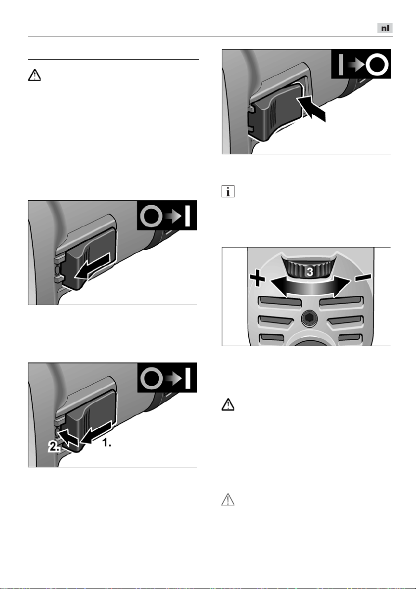
L 3709 -115, L 3709 -125, LE 9-10 125, L 10-10 125, L 801, L 1001
Gebruiksaanwijzing
Trek voor alle werkzaamheden aan de
WAARSCHUWING!
haakse slijpmachine de stekker uit het
stopcontact.
Voor de ingebruikneming
Pak de haakse slijpmachine uit en controleer
of alles compleet is meegeleverd en er geen
transportschade is.
In- en uitschakelen
Gebruik voor korte duur zonder
vergren-deling:
Duw de schakelaar naar voren en houd
deze vast.
Als u de machine wilt uitschakelen,
laat u de schakelaar los.
Continu gebruik met vergrendeling:
Duw de schakelaar naar voren (1.) en ver-
grendel vervolgens de schakelaar door
deze vooraan in te drukken (2.).
Als u de machine wilt uitschakelen,
ontgrendelt u de schakelaar door
deze achteraan in te drukken.
LET OP
Nadat de stroom is uitgevallen, start het
ingeschakelde gereedschap niet opnieuw.
Vooraf instelbaar toerental
(alleen LE 9-10 125)
Als u het werktoerental wilt instellen, zet u het
stelwiel op de gewenste waarde.
Veiligheidsbeschermkap
(L 3709-115, L 801, L 3709-125)
WAARSCHUWING!
Nooit zonder de veiligheidsbeschermkap
werken.
Voor de aanpassing aan de te verrichten
werkzaamheden kunt u de veiligheidsbeschermkap zonder hulpgereedschap
verstellen.
Voor doorslijpen moet een speciale
doorslijpbeschermkap worden gebruikt.
VOORZICHTIG!
Verwondingsgevaar!
Draag werkhandschoenen!
Trek de stekker uit de contactdoos.
75
Page 76

L 3709 -115, L 3709 -125, LE 9-10 125, L 10-10 125, L 801, L 1001
Draai de veiligheidsbeschermkap
in de gewenste stand.
Snelspanschroef
(LE 9-10 125, L 10-10 125, L 1001)
WAARSCHUWING!
Werk bij afbraam- en
doorslijpwerkzaamheden nooit zonder
beschermkap.
Trek de stekker uit de contactdoos.
Maak de spanhendel (a) los.
Verstel de beschermkap.
Slijpgereedschap bevestigen
of wisselen
Trek de stekker uit de contactdoos.
Arretering van uitgaande as indrukken en
ingedrukt houden (1.).
Draai met de spansleutel de spanmoer
tegen de wijzers van de klok in los van
de uitgaande as en verwijder de
spanmoer (2.).
Leg de slijpschijf in de juiste positie
op de uitgaande as.
Schroef (b) zo vast aandraaien dat de
spanhendel net nog met de hand kan
worden gespannen.
Draai de spanhendel weer vast.
Voor doorslijpen moet een speciale
snelspan-doorslijpbeschermkap worden
gebruikt.
76
Draai de spamoer met de kraag naar
boven op de uitgaande as.
Druk op de blokkering van de uitgaande
as en houd deze ingedrukt.
Draai de spanmoer met de spansleutel
vast.
Steek de stekker in de contactdoos.
Schakel de haakse slijpmachine
in met de schakelaar zonder deze
vast te klikken en laat de haakse
slijpmachine gedurende ca. 30 seconden
lopen. Controleer de machine op
onbalans en trillingen.
Schakel de haakse slijpmachine uit.
Page 77

L 3709 -115, L 3709 -125, LE 9-10 125, L 10-10 125, L 801, L 1001
Tips voor de werkzaamheden
Na het uitschakelen loopt het
slijpgereedschap nog korte tijd uit.
Afbramen
Gebruik nooit doorslijpschijven voor
afbraam-werkzaamheden.
– Aanzethoek 20°–40° voor optimale
– Beweeg de haakse slijpmachine met
Doorslijpen
Voor doorslijpwerkzaamheden moet een
speciale doorslijpbeschermkap worden
gebruikt.
– Druk de machine niet aan.
– De haakse slijpmachine moet altijd
– Pas de voeding aan het te bewerken
Zie www.flex-tools.com
over de producten van de fabrikant.
LET OP
WAARSCHUWING!
afname.
matige druk heen en weer.
Daardoor wordt het werkstuk niet te heet
en ontstaan er geen verkleuringen.
Bovendien komen er zo geen groeven
in het werkstuk.
WAARSCHUWING!
Houd de machine niet schuin.
Laat de machine niet oscilleren.
in tegengestelde richting werken.
Anders kan de schijf ongecontroleerd
uit de groef springen.
materiaal aan. Hoe harder het materiaal,
hoe langzamer u naar voren beweegt.
voor meer informatie
Onderhoud en verzorging
WAARSCHUWING!
Trek voor alle werkzaamheden aan de
haakse slijpmachine de stekker uit het
stopcontact.
Reiniging
WAARSCHUWING!
Bij het bewerken van metalen kan zich
bij intensief gebruik geleidend stof in het
machinehuis ophopen.
Gevaar voor beschadiging van de veiligheidsisolatie! Gebruik de machine via
een aardlekschakelaar (inschakelstroom
30 mA).
Reinig de machine en de ventilatieopeningen regelmatig. De frequentie van de reiniging is afhankelijk van het bewerkte
materiaal en van de duur van het gebruik.
Blaas de binnenzijde van het machinehuis
met de motor regelmatig met droge perslucht door.
Koolborstels
De haakse slijpmachine is voorzien
van zelfuitschakelende koolborstels.
Na het bereiken van de slijtagegrens
schakelen de koolborstels de haakse
slijpmachine automatisch uit.
LET OP
Gebruik uitsluitend originele vervangingsonderdelen van de fabrikant. Bij het gebruik
van onderdelen van een andere fabrikant
vervallen de garantieverplichtingen van
de fabrikant.
Door de luchttoevoeropeningen aan de
achterzijde kunnen de koolborstelvonken
tijdens het gebruik worden geobserveerd.
Schakel de haakse slijpmachine onmiddellijk uit bij sterke vonkontwikkeling van
de koolborstels.
Geef de haakse slijpmachine vervolgens af
bij een door de fabrikant erkende klantenservice.
77
Page 78

L 3709 -115, L 3709 -125, LE 9-10 125, L 10-10 125, L 801, L 1001
Klaus Peter Weinper
Head of Quality
Department (QD)
Eckhard Rhle
Manager Research &
Development (R & D)
Machinekop
LET OP
Draai de schroeven op de machinekop
tijdens de garantietijd niet los.
Anders vervallen de garantieverplichtingen
van de fabrikant.
Reparaties
Laat reparaties uitsluitend uitvoeren door
een door de fabrikant erkende klantenservice.
Vervangingsonderdelen
en toebehoren
Zie voor meer toebehoren, in het bijzonder
slijpgereedschappen, de catalogi van
de fabrikant.
Explosietekeningen en onderdelenlijsten
vindt u op onze website:
www.flex-tools.com
Afvoeren van verpakking
en machine
WAARSCHUWING!
Maak een versleten machine onbruikbaar
door het netsnoer te verwijderen.
Alleen voor EU-landen
Gooi elektrische gereedschappen
niet bij het huisvuil.
Volgens de Europese richtlijn 2012/19/EU
betreffende afgedankte elektrische en elektronische apparatuur en de omzetting van
de richtlijn in nationaal recht moeten
versleten elektrische gereedschappen apart
worden ingezameld en op een voor het
milieu verantwoorde wijze opnieuw worden
gebruikt.
LET OP
Vraag uw vakhandel naar de mogelijkheden
om uw oude gereedschap af geven.
-Conformiteit
Wij verklaren als alleen verantwoordelijke dat
het onder „Technische gegevens”
beschreven product voldoet aan de volgende
normen en normatieve documenten:
EN 60745 volgens de bepalingen van
de richtlijnen 2014/30/EU, 2006/42/EG,
2011/65/EU.
Verantwoordelijk voor technische
documentatie:
FLEX-Elektrowerkzeuge GmbH, R & D
Bahnhofstrasse 15, D-71711 Steinheim/Murr
16-06-2016; FLEX-Elektrowerkzeuge GmbH
Bahnhofstrasse 15, D-71711 Steinheim/Murr
Uitsluiting van aansprakelijkheid
De fabrikant en zijn vertegenwoordiger zijn niet
aansprakelijk voor schade en verloren winst
door onderbreking van de werkzaamheden
die door het product of het niet-mogelijke
gebruik van het product zijn veroorzaakt.
De fabrikant en zijn vertegenwoordiger zijn
niet aansprakelijk voor schade die door ondeskundig gebruik of in combinatie met producten
van andere fabrikanten is veroorzaakt.
78
Page 79

L 3709 -115, L 3709 -125, LE 9-10 125, L 10-10 125, L 801, L 1001
Indhold
Anvendte symboler . . . . . . . . . . . . . . . . 79
Symboler på maskinen . . . . . . . . . . . . . 79
For Deres egen sikkerheds skyld . . . . . 79
Støj og vibration . . . . . . . . . . . . . . . . . . 82
Tekniske data . . . . . . . . . . . . . . . . . . . . 83
Oversigt . . . . . . . . . . . . . . . . . . . . . . . . . 84
Brugsanvisning . . . . . . . . . . . . . . . . . . . 85
Vedligeholdelse og eftersyn . . . . . . . . . 87
Bortskaffelseshenvisninger . . . . . . . . . . 88
-Overensstemmelse . . . . . . . . . . . . . 88
Ansvarsudelukkelse . . . . . . . . . . . . . . . 88
Anvendte symboler
ADVARSEL!
Betegner en umiddelbar truende fare.
Ved tilsidesættelse af henvisningen opstår
der livsfare eller fare for alvorlig
tilskadekomst.
FORSIGTIG!
Betegner en mulig farlig situation.
Ved tilsidesættelse af henvisningen er der
fare for tilskadekomst, eller der kan opstå
materielle skader.
BEMÆRK
Betegner anvendelsestips og vigtige
informationer.
Symboler på maskinen
Læs betjeningsvejledningen,
inden maskinen tages i brug!
Benyt øjenværn!
Beskyttelsesklasse II (helt isoleret)
Henvisning om bortskaffelse af
den udtjente maskine (se side 88)!
For Deres egen sikkerheds skyld
ADVARSEL!
Læs følgende før vinkelsliberen benyttes
og følg instruktionerne:
–
denne betjeningsvejledning,
–
„Generelle sikkerhedsanvisninger“
for håndtering af elværktøjer i vedlagte
hæfte (skrift-nr.: 315.915),
–
de for anvendelsesstedet gældende
regler og forskrifter vedrørende
forebyggelse af ulykker.
Denne vinkelsliber er konstrueret i henhold
til det aktuelle tekniske niveau og de
anerkendte sikkerhedstekniske regler.
Alligevel kan der ved dets brug opstå fare
for brugers eller tredjemands liv og lemmer,
maskinen kan beskadiges, eller der kan
opstå andre materielle skader.
Vinkelsliberen må kun benyttes
–
til det dertil beregnede formål,
–
i sikkerhedsteknisk upåklagelig tilstand.
Fejl, der har negativ indflydelse på
sikkerheden, skal afhjælpes omgående.
Bestemmelsesmæssig brug
Denne vinkelsliber er beregnet
– til erhvervsmæssig brug inden for industri
og håndværk,
– til slibning og overskæring af metal og
sten ved tørslibning; til skæring skal der
bruges en særskilt beskyttelsesskærm,
– til brug med slibeværktøj og tilbehør som
angivet i denne vejledning eller som
anbefales af producenten og er godkendt
til en periferihastighed på 80 m/s.
Kædefræseskiver og savblade er f.eks. ikke
tilladt.
Sikkerhedsinstrukser
ADVARSEL!
Læs venligst alle sikkerhedsinstrukser,
anvisninger, afbildninger og specifikationer,
der er leveret sammen med el-værktøjet.
I tilfælde af manglende overholdelse af
sikkerhedsinstrukserne og anvisningerne er
der risiko for elektriske stød, brand og/eller
alvorlige kvæstelser. Opbevar venligst alle
sikkerhedsinstrukser og anvisninger for
senere brug.
79
Page 80

L 3709 -115, L 3709 -125, LE 9-10 125, L 10-10 125, L 801, L 1001
Fælles sikkerhedsinstrukser til slibning
og skærearbejde
Dette elværktøj skal anvendes som sliber
og skæremaskine. Følg alle sikkerhedshenvisninger, anvisninger, illustrationer og
data, der følger med apparatet.
Hvis efterfølgende anvisninger
tilsidesættes, kan det medføre elektriske
stød, brand og/eller alvorlige kvæstelser.
Dette elværktøj er ikke egnet til
sandpapirslibning, arbejder med
trådbørster og polering.
Hvis elværktøjet anvendes til andre
formål, end det er beregnet til, kan
personer udsættes for fare og kvæstes
Der må ikke anvendes tilbehør, der ikke
specielt er beregnet og anbefalet
af fabrikanten til dette elværktøj.
Selv om tilbehøret kan fastgøres
på elværktøjet, er det ikke en garanti
for en sikker brug.
Det tilladte omdrejningstal af indsats-
værktøjet skal være mindst lige så højt
som det på elværktøjet angivne maksimale omdrejningstal.
Tilbehør der drejer hurtigere end tilladt
kan brække og kastes rundt.
Det anvendte indsatsværktøjs yderdia-
meter og tykkelse skal svare til målangivelserne for elværktøjet.
Forkert dimensionerede indsatsværktøjer kan ikke afskærmes tilstrækkeligt
eller kontrolleres.
Indsatsværktøj med gevindindsats skal
passe nøjagtigt på slibespindlens gevind.
Ved indsatsværktøj, der monteres med en
flange, skal indsatsværktøjets huldiameter
passe til flangens holdediameter.
Indsatsværktøjer, der ikke passer nøjagtigt på elværktøjets slibespindel, drejer
ujævnt, vibrerer kraftigt, og det kan medføre, at man mister kontrollen over dem.
Beskadigede indsatsværktøjer må ikke
anvendes. Kontrollér altid før brug
indsatsværktøj som f.eks. slibeskiver for
afsplintninger og revner, slibebagskiver
for revner, slid eller stærkt slid, trådbørster for løse eller brækkede tråde.
Hvis elværktøjet er faldet på gulvet,
kontrollér, om det er beskadiget, eller
anvend et ubeskadiget indsatsværktøj.
.
Når indsatsværktøjet er kontrolleret og
sat på plads, skal du holde dig selv og
andre personer, der befinder sig i
nærheden, uden for det niveau, hvor
indsatsværktøjet roterer. Lad apparatet
køre et minut med maks. omdrejningstal.
Beskadigede indsatsværktøjer brækker
for det meste i løbet af denne testtid.
Bær personligt beskyttelsesudstyr.
Benyt helmaske til ansigtet, øjenværn
eller beskyttelsesbriller, afhængigt
af det udførte arbejde.
Benyt afhængigt af arbejdets art støvmaske, høreværn, beskyttelseshandsker
eller specialforklæde, der beskytter mod
små slibe- og materialepartikler.
Øjnene skal beskyttes mod fremmedlegemer, der kastes rundt og som opstår
i forbindelse med forskelligt arbejde.
Støv- eller åndedrætsmasken skal filtrere
det støv, der opstår under arbejdet.
Udsættes du for kraftig støj i længere tid,
kan du lide høretab.
Sørg for at andre personer opholder sig
i sikker afstand af dit arbejdsområde.
Enhver, der betræder arbejdsområdet,
skal bruge personligt beskyttelsesudstyr.
Brudstykker af arbejdsemnet eller brækkede indsatsværktøjer kan blive kastet
rundt og medføre kvæstelser, også uden
for selve arbejdsområdet.
Hold kun apparatet fast i de isolerade
grepsflader, når der arbejdes på steder,
hvor indsatsværktøjet vil kunne ramme
skjulte strømledninger eller apparatets
eget netkabel.
Kontakt med en spændingsførende ledning kan også sætte metaldele på apparatet under spænding og medføre elektriske stød.
Hold netkablet borte fra roterende
indsatsværktøjer.
Mister du kontrollen over apparatet,
kan netkablet skæres over eller rammes,
og din hånd eller arm kan trækkes ind
i det roterende indsatsværktøj.
Læg aldrig elværktøjet til side før det står
helt stille.
Det roterende indsatsværktøj kan
komme i kontakt med fralægningsfladen,
hvorved du kan miste kontrollen over
elværktøjet.
80
Page 81

L 3709 -115, L 3709 -125, LE 9-10 125, L 10-10 125, L 801, L 1001
Lad ikke elværktøjet køre, mens det
bæres.
Ved tilfældig kontakt med det roterende
indsatsværktøj kan dit tøj blive fanget,
hvorved indsatsværktøjet kan bore
sig ind i din krop.
Rengør ventilationsslidserne på elværk-
tøjet regelmæssigt.
Motorblæseren trækker støv ind i huset,
og store mængder metalstøv kan forårsage elektrisk fare.
Ikke anvend elværktøjet i nærheden
af brændbare materialer.
Gnister kan antænde disse materialer.
Ikke anvend indsatsværktøjer,
der kræver flydende kølemidler.
Brug af vand eller andre flydende kølemidler kan medføre, at der opstår elektriske stød.
Tilbageslag og tilsvarende sikkerhedshenvisninger
Tilbageslag er en pludselig reaktion, som
skyldes, at et roterende indsatsværktøj,
f.eks. slibeskive, slibetallerken, trådbørste
osv., har sat sig fast eller blokerer.
Fastsættelse eller blokering medfører
et pludseligt stop af det roterende indsatsværktøj. Derved accelereres et ukontrolleret
elværktøj mod indsatsværktøjets omdrejningsretning på blokeringsstedet.
Sidder f.eks. en slibeskive fast i et emne
eller blokerer i et arbejdsemne, kan kanten
på slibeskiven, der dykker ned i arbejdsemnet, blive siddende, hvorved slibeskiven
brækker af eller giver tilbageslag.
Slibeskiven bevæger sig hen imod eller
bort fra brugeren, afhængigt af skivens
omdrejningsretning på blokeringsstedet.
Derved kan slibeskiver også brække.
Et tilbageslag skyldes forkert eller
fejlbehæftet brug af elværktøjet.
Det kan forhindres ved at træffe egnede
forsigtighedsforanstaltninger, der beskrives
nedenfor.
Hold godt fast i elværktøjet og sørg for,
at både krop og arme befinder sig
i en position, der modvirker tilbageslagskræfterne. Anvend altid ekstrahåndtaget, hvis et sådant findes, for at
have så meget kontrol som muligt over
tilbageslag-skræfterne eller reaktionsmomenterne, når apparatet kører op
i hastighed. Brugeren kan beherske
tilbageslags- og reaktionskræfterne ved
at træffe egnede sikkerheds-
foranstaltninger.
Sørg for at hænderne aldrig kommer
i nærheden af de roterende indsats-
værktøjer.
Indsatsværktøjet kan bevæge sig
hen over din hånd i forbindelse med
et tilbageslag.
Undgå at kroppen befinder sig i det
område, hvor elværktøjet bevæger
sig i forbindelse med et tilbageslag.
Tilbageslaget driver elværktøjet i modsat
retning af slibeskivens bevægelse
på blokeringsstedet.
Vær særlig forsigtig ved arbejder i om-
råder som f.eks. hjørner, skarpe kanter
osv. Det skal forhindres, at indsatsværk-
tøjet slår tilbage fra arbejdsemnet og
sætter sig fast.
Det roterende indsatsværktøj har ten-
dens til at sætte sig fast, når det anven-
des i hjørner, skarpe kanter, eller hvis
det springer tilbage.
Dette medfører, at man mister kontrollen,
eller der opstår et tilbageslag.
Brug ikke kædesavklinger eller
fortandede savklinger.
Sådanne indsatsværktøjer bevirker
ofte et tilbageslag, eller at man mister
kontrollen over elværktøjet.
Særlige sikkerhedsanvisninger
vedrørende slibning og
slibeskiveskæring
Der må kun anvendes slibelegemer,
der er godkendt til elværktøjet og beskyt-
telseskapper, der er beregnet til disse
slibelegemer.
Slibelegemer, der ikke er beregnet
til elværktøjet, kan ikke afskærmes
tilstrækkeligt og er usikre.
Krøppede slibeskiver skal monteres,
så deres slibeflade ikke rager ud over
niveauet på beskyttelseshættens kant.
En forkert monteret slibeskive, der rager
ud over niveauet på beskyttelseshættens
kant, kan ikke afskærmees tilstrækkeligt.
81
Page 82

L 3709 -115, L 3709 -125, LE 9-10 125, L 10-10 125, L 801, L 1001
Beskyttelseskappen skal være anbragt
sikkert på el-værktøjet og være indstillet
på en sådan måde, at der opnås maks.
sikkerhed, dvs. at den mindste del af
slibeskiven peger åbent hen imod
betjeningspersonen.
Beskyttelseskappen
er med til at beskytte betjeningsper-sonen
mod brudstykker, tilfældig kontakt med
slibeskiven/slibestiften samt gnister, der
kan sætte ild i tøjet.
Slibelegemer må kun anvendes til de an-
befalede anvendelsesmuligheder.
Eksempel: Slib aldrig med sidefladen
af en kapskive.
Kapskiver er beregnet til at fjerne
materiale med kanten af skiven.
Udsættes disse slibetallerkner for sidevendt kraftpåvirkning, kan de knække.
Anvend altid ubeskadigede spænde-
flanger i rigtig størrelse og form til den
valgte slibeskive. Egnede flanger støtter
slibeskiven og reducerer således
risikoen for, at slibeskiven brækker.
Flanger til kapskiver kan være anderledes end flanger til andre slibeskiver.
Anvend ikke slidte slibeskiver fra større
elværktøjer.
Slibeskiver til større elværktøjer er ikke
dimensioneret til højere omdrejningstal
på mindre elværktøjer og kan brække.
Yderligere særlige sikkerhedsanvisninger vedrørende slibeskiveskæring
Undgå at skæreskiven blokerer, eller
at den udsættes for et for højt pressetryk.
Foretag ikke meget dybe snit.
Overbelastning af skæreskiven medfører
større slitage og tendens til, at den sætter
sig fast eller blokerer.
Dette bevirker et evt. tilbageslag, eller
at slibelegemet brækker.
Undgå området for og bag ved den
roterende skæreskive.
Bevæger du skæreskiven i emnet væk
fra dig selv, kan elværktøjets roterende
skæreskive slynges direkte tilbage mod
dig i tilfælde af et tilbageslag.
Sidder skæreskiven i klemme eller
afbryder du arbejdet, slukkes maskinen
og holdes roligt, indtil skæreskiven står
helt stille. Forsøg aldrig at trække
skæreskiven ud af snittet, mens den
roterer, da dette kan føre til et tilbageslag. Lokalisér fejlen og afhjælp årsagen
til fastklemningen.
Tænd aldrig elværktøjet så længe
det befinder sig i arbejdsemnet.
Sørg for at skæreskiven først når
op på sit fulde omdrejningstal, før
du forsigtigt fortsætter savning.
Ellers kan skæreskiven sætte sig
i klemme, springe ud af arbejdsemnet
eller forårsage et tilbageslag.
Understøt plader eller store arbejdsem-
ner for at reducere risikoen for et tilbageslag som følge af en fastklemt skæreskive. Store arbejdsemner kan bøje sig
på grund af egenvægten. Arbejdsemnet
skal støttes på begge sider af skæreskiven, både i nærheden af skæresnittet
og ved kanten.
Vær særlig forsigtig ved „lommesnit“
i forhåndenværende vægge eller andre
områder, der ikke kan ses.
Den neddykkede skæreskive kan forårsage et tilbageslag, når der skæres
i gas- eller vandledninger, elledninger
eller andre genstande.
Videre sikkerhedshenvisninger
Netspændingen og spændingsangivel-
sen på typeskiltet skal stemme overens.
Tryk kun på spindellåsen når slibe-
værktøjet står stille.
Støj og vibration
BEMÆRK
Værdierne for det A-vægtede støjniveau
samt de samlede svingningsværdier
fremgår af tabellen „Tekniske data“.
Støj- og svingningsværdierne er beregnet
ifølge EN 60745.
FORSIGTIG!
De angivne måleværdier gælder for nye
apparater. Støj- og svingningsværdierne
ændrer sig ved daglig brug.
82
Page 83

L 3709 -115, L 3709 -125, LE 9-10 125, L 10-10 125, L 801, L 1001
Det svingningsniveau, der er angivet
BEMÆRK
i disse anvisninger, er blevet målt i henhold
til en standardiseret måleproces i EN 60745
og kan bruges til at sammenligne elværktøjerne. Det egner sig også til en foreløbig
vurdering af svingnings-belastningen.
Det angivne svingningsniveau repræsenterer elværktøjets hovedsagelige anvendelse. Hvis elværktøjet dog benyttes
til andre formål, med afvigende indsatsværktøjer eller det vedligeholdes utilstrækkeligt, kan svingningsniveauet ændre sig.
Dette kan øge svingningsbelastningen
betydeligt i hele arbejdstidsrummet.
For nøjagtigt at kunne vurdere svingningsbelastningen bør man også tage højde
for de tider, hvor apparatet er slukket eller
kører, men ikke bruges. Dette kan reducere
svingningsbelastningen betydeligt i hele
arbejdstidsrummet.
Fastlæg derfor yderligere sikkerhedsforanstaltninger til beskyttelse af brugeren
imod påvirkning af svingninger, f.eks.
vedligeholdelse af elværktøj og indsatsværktøjer, varmholdelse af hænder,
organisation af arbejdsforløb
FORSIGTIG!
Ved et lydtryk på over 85 dB(A) skal der
benyttes høreværn.
Tekniske data
L 3709-115 L 3709-125
L 801
Apparattype Vinkelsliber
Slibeværktøjets max. Ø
Slibeværktøjets tykkelse
Styrehul
mm 115 125 125 125
mm 1–6
mm 22,23
Spindelgevind
Omdrejningstal
Optagen effekt
Afgivet effekt
omdr./min
W 750 800 900 1010
W 450 480 530 600
12500 12000 6000–11500 10000
Vægt i henhold til "EPTAprocedure 01/2003" (uden
kg 1,9 2,0 2,2
kabel)
Beskyttelsesklasse
A-vægtet støjniveau i henhold til EN 60745 (se „Støj og vibration“):
Lydtryksniveau L
Lydeffektniveau L
Usikkerhed K
pA
WA
dB(A)
dB(A)
db
84,6 87 91
95,6 98 102
Samlet svingningsværdi i henhold til EN 60745 (se „Støj og vibration“):
Emmisionsværdi a
overfladeslibning
Emmisionsværdi ah ved
skærearbejder
Usikkerhed K
ved
h
m/s
m/s
m/s
2
2
2
6,5 6,5 6,6
6,3 8,1 6,2
LE 9-10 125 L 10-10 125
M14
II/
3
1,5
.
L 1001
83
Page 84

L 3709 -115, L 3709 -125, LE 9-10 125, L 10-10 125, L 801, L 1001
Oversigt
I nærværende vejledning beskrives forskellige elværktøjer.
Beskrivelsen kan afvige i detaljerne fra den købte maskine.
1 Spindel
2 Gevindflange
a Spændemøtrik
b Spændeflange
3 Beskyttelseshætte
4 Håndtag
Håndtag monterbart på venstre og
højre side.
5 Spindellås
Til låsning af spindlen ved
værktøjsskift.
6 Gearhoved
Med luftudslip og omdrejningsret-
ningspil.
84
7 Vippekontakt
Tænder og slukker maskinen.
Med indgrebsstilling for konstant drift.
8 Netkabel 4,0 m med netstik
9 Topnøgle
10 Typeskilt (ikke vist)
11 Indstillingshjul til forvalg af omdrej-
ningstal
(kun LE 9-10 125)
Page 85
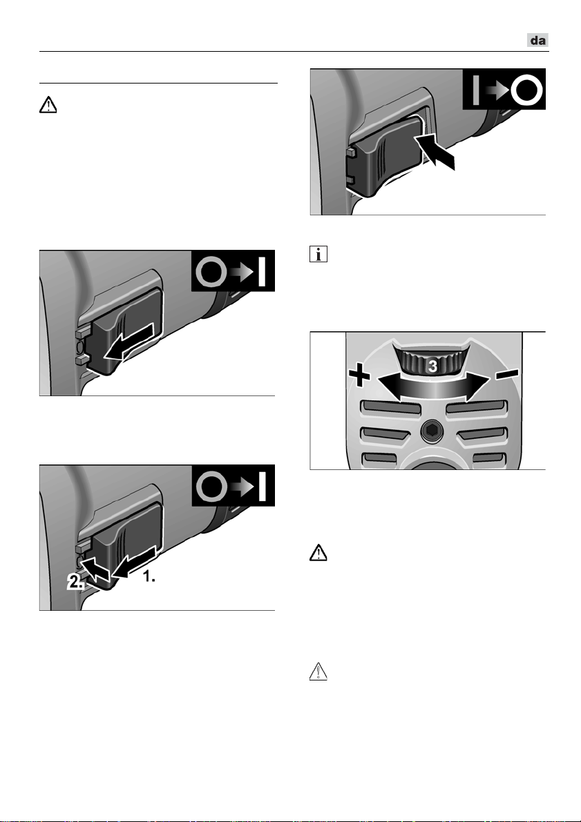
L 3709 -115, L 3709 -125, LE 9-10 125, L 10-10 125, L 801, L 1001
Brugsanvisning
Træk altid netstikket ud før der arbejdes
ADVARSEL!
på vinkelsliberen.
Inden ibrugtagning
Pak vinkelsliberen ud og kontrollér, om leveringen er komplet eller om den er blevet
beskadiget under transporten.
Tænd og sluk
Kortvarig drift uden indgreb:
Skub vippekontakten fremad og hold den
fast.
Slip vippekontakten for at slukke.
Konstant drift med indgreb:
Skub vippekontakten fremad (1.) og lad
den gå i indgreb ved at trykke på forreste
ende (2.).
Frigør vippekontakten ved at trykke
på bagerste ende for at slukke.
BEMÆRK
Efter strømsvigt starter den tændte maskine
ikke igen.
Forvalg af omdrejningstal
(kun LE 9-10 125)
Stil indstillingshjulet på den ønskede værdi
for indstilling af arbejdshastigheden.
Sikkerheds-beskyttelseshætte
(L 3709-115, L 801, L 3709-125)
ADVARSEL!
Arbejd aldrig uden sikkerhedsbeskyttelseshætte.
Sikkerheds-beskyttelseshætten kan justeres
uden brug af værktøj og tilpasses arbejdsopgaven.
Til skæring skal der anvendes en særskilt
beskyttelsesskærm.
FORSIGTIG!
Kvæstelsesfare! Bær
beskyttelseshandsker.
Træk netstikket ud.
85
Page 86
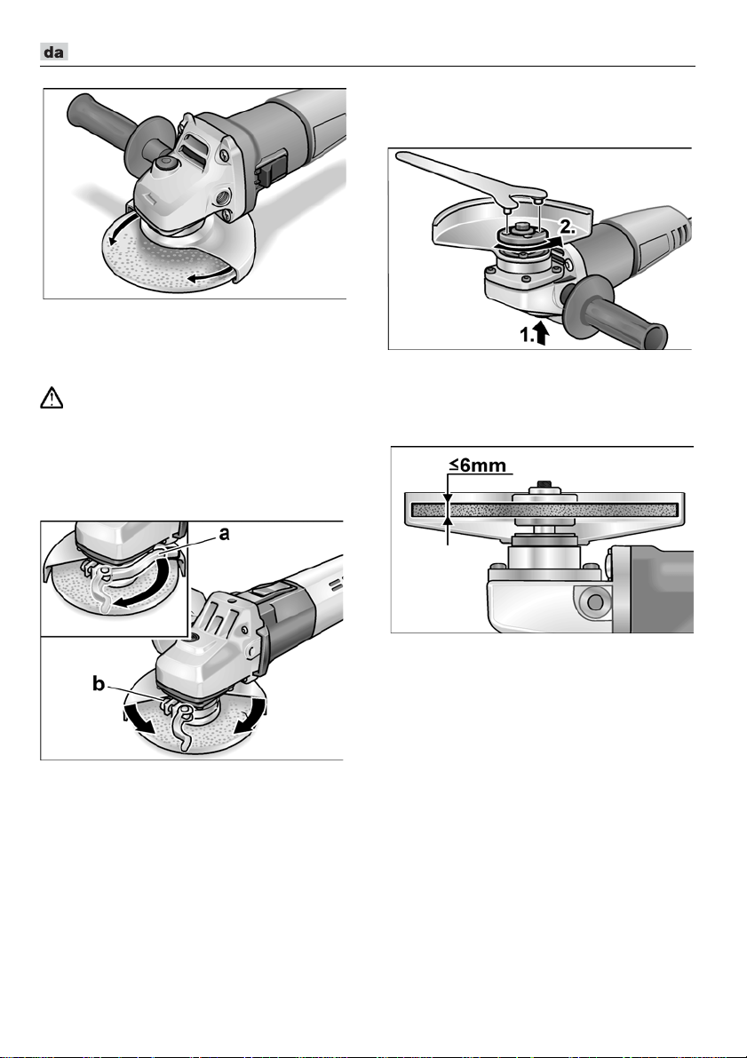
L 3709 -115, L 3709 -125, LE 9-10 125, L 10-10 125, L 801, L 1001
Drej sikkerheds-beskyttelseshætten
til nødvendige position.
Hurtigspænd-beskyttelseshætte
(LE 9-10 125, L 10-10 125, L 1001)
ADVARSEL!
Arbejd aldrig uden beskyttelseshætte, når
der udføres grove arbejder og
skærearbejder.
Træk netstikket ud.
Løsn (a) spændearmen.
Justér beskyttelseshætten.
Fastgøring eller udskiftning
af slibeværktøj
Træk netstikket ud.
Tryk på spindellåsen og hold den inde (1.).
Løsgør spændemøtrikken på spindlen
med topnøglen ved at dreje den mod uret
og tag den af (2.).
Læg slibeskiven på i rigtig position.
Spænd skruen (b) så fast, at spænde-
håndtaget netop kan spændes med
hånden.
Spænd spændearmen fast igen.
Til skæring skal der anvendes en særskilt
hurtigspænd-beskyttelsesskærm.
86
Skru spændemøtrikken på spindlen med
brystet opadvendt.
Tryk på spindellåsen og hold den inde.
Spænd spændemøtrikken fast med
topnøglen.
Sæt netstikket i stikkontakten.
Tænd vinkelsliberen med vippekontak-
ten (uden indgreb) og lad vinkelsliberen
løbe ca. 30 sekunder. Kontrollér den for
ubalance og vibrationer.
Sluk vinkelsliberen.
Page 87
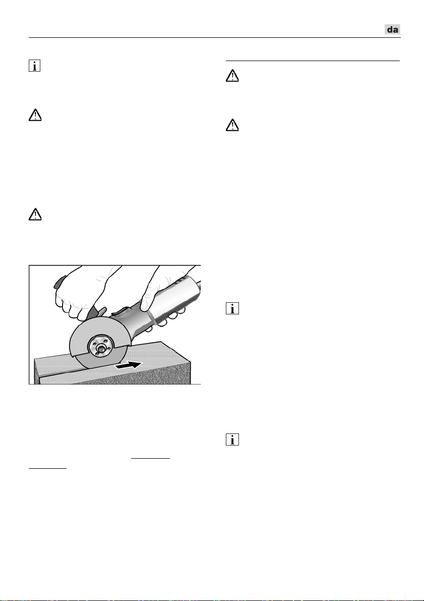
L 3709 -115, L 3709 -125, LE 9-10 125, L 10-10 125, L 801, L 1001
Arbejdsinstrukser
BEMÆRK
Slibeværktøjet har et kort efterløb efter
slukning.
Grovslibning
ADVARSEL!
Anvend aldrig skæreskiver til grovslibning.
– Indstillingsvinkel 20–40° for optimal
bearbejdning.
– Bevæg vinkelsliberen frem og tilbage ved
at trykke lidt på den. Derved bliver emnet
ikke for varmt og misfarves ikke.
Desuden opstår der ingen riller.
Bortslibning
ADVARSEL!
Til bortslibning skal der anvendes
en særskilt beskyttelsesskærm.
– Tryk ikke, pas på at vinkelsliberen ikke
sætter sig fast eller svinger.
– Vinkelsliberen skal altid arbejde i
modløb. Den vil ellers kunne springe
ukontrolleret ud af rillen.
– Tilpas fremskydningen af materialet,
der bearbejdes; jo hårdere, desto
langsommere.
Besøg vores hjemmeside www.flextools.com for flere oplysninger.
Vedligeholdelse og eftersyn
ADVARSEL!
Træk altid netstikket ud før der arbejdes
på vinkelsliberen.
Rengøring
ADVARSEL!
Der kan aflejres lededygtigt støv i husets
indre ved ekstrem anvendelse i forbindelse
med bearbejdning af metaller.
Dette har negativ indflydelse på beskyttelsesisoleringen! Maskinen skal drives via
et HFI-relæ (belastningssikring 30 mA).
Rengør apparatet og ventilationsslidserne
regelmæssigt. Intervallerne afhænger
af materialet, der skal bearbejdes,
og af brugsvarigheden.
Blæs husets indre med motor ud regelmæssigt med tør trykluft.
Kulbørster
Vinkelsliberen er udstyret med udkoblingskul. Når udkoblingskullenes slidgrænse nås,
slukkes vinkelsliberen automatisk.
BEMÆRK
Der må kun anvendes originale dele
fra fabrikanten ved udskiftning.
Fabrikantens garantiforpligtelser bortfalder
ved benyttelse af fremmede fabrikater.
Ilden fra kullet kan iagttages gennem
de bagerste luftindgangsåbninger under
brugen. Hvis ilden fra kullet bliver kraftigt,
skal vinkelsliberen slukkes omgående.
Aflever vinkelsliberen til et autoriseret
kundeservice-værksted.
Gearkasse
BEMÆRK
Skruerne på gearhovedet må ikke løsnes
i garantiperioden.
Ved tilsidesættelse af dette bortfalder
fabrikantens garantiforpligtelser.
Reparationer
Reparationer må udelukkende udføres
af et af fabrikanten autoriseret kundeservice-værksted.
87
Page 88
L 3709 -115, L 3709 -125, LE 9-10 125, L 10-10 125, L 801, L 1001
Klaus Peter Weinper
Head of Quality
Department (QD)
Eckhard Rhle
Manager Research &
Development (R & D)
Reservedele og tilbehør
Andet tilbehør, især slibeværktøjer, findes
i katalogerne fra producenten.
Eksplosionstegninger og reservedelslister
findes på vores hjemmeside:
www.flex-tools.com
Bortskaffelseshenvisninger
ADVARSEL!
Gør udtjente maskiner ubrugelige ved
at fjerne netkablet.
Kun for EU-lande
Elektroværktøjer er ikke normalt
husholdningsaffald.
I henhold til europæisk direktiv 2012/19/EU
om affald af elektrisk og elektronisk udstyr
og omsætning til national ret skal udtjente
elektriske værktøjer samles separat og afleveres på et opsamlingssted for materialegenvinding.
BEMÆRK
Faghandlen giver oplysninger om bortskaffelsesmuligheder!
-Overensstemmelse
Vi erklærer under almindeligt ansvar,
at produktet beskrevet under „Tekniske data“
er i overensstemmelse med følgende
standarder eller normative dokumenter:
EN 60745 ifølge bestemmelserne i direktiv
2014/30/EU, 2006/42/EF, 2011/65/EU.
Ansvarlig for det tekniske dossier:
FLEX-Elektrowerkzeuge GmbH, R & D
Bahnhofstrasse 15, D-71711 Steinheim/Murr
Ansvarsudelukkelse
Fabrikanten og hans repræsentant hæfter ikke
for skader og fortjeneste som virksomheden
evt. er gået glip af som følge af driftsafbrydelse
i virksomheden, forårsaget af produktet eller
fordi produktet ikke kunne benyttes.
Fabrikanten og dennes repræsentant hæfter
ikke for skader opstået som følge af usagkyndig anvendelse eller i forbindelse med produkter fra andre fabrikanter
.
16-06-2016; FLEX-Elektrowerkzeuge GmbH
Bahnhofstrasse 15, D-71711 Steinheim/Murr
88
Page 89
L 3709 -115, L 3709 -125, LE 9-10 125, L 10-10 125, L 801, L 1001
Innhold
Symboler som brukes . . . . . . . . . . . . . . 89
Symbolene på apparatet . . . . . . . . . . . . 89
For din egen sikkerhet . . . . . . . . . . . . . . 89
Støy og vibrasjon . . . . . . . . . . . . . . . . . 92
Tekniske data . . . . . . . . . . . . . . . . . . . . 93
Et overblikk . . . . . . . . . . . . . . . . . . . . . . 94
Bruksanvisning . . . . . . . . . . . . . . . . . . . 95
Vedlikehold og pleie . . . . . . . . . . . . . . . 97
Henvisninger om skroting . . . . . . . . . . . 98
-Konformitet. . . . . . . . . . . . . . . . . . . . 98
Utelukkelse av ansvar . . . . . . . . . . . . . . 98
Symboler som brukes
ADVARSEL!
Gjør oppmerksom på en umiddelbar
truende fare. Det er kan oppstå livsfare eller
fare for alvorlige skader dersom dette ikke
blir fulgt.
FORSIKTIG!
Gjør oppmerksom på en situasjon som kan
være farlig. Det kan oppstå skade på
personer eller ting dersom dette ikke blir
fulgt.
HENVISNING
Betyr tips og informasjoner om bruken.
Symbolene på apparatet
Les igjennom disse før bruk!
Bruk øyevern!
Beskyttelsesklasse II
(fullstendig isolert)
Henvisninger om avskaffing av
gammelt apparat (se side 98)!
For din egen sikkerhet
ADVARSEL!
Før bruk av vinkelsliperen må du lese
igjennom og ta hensyn til følgende:
–
betjeningsveiledningen som er vedlagt,
–
de “generelle sikkerhetshenvisningene”
i omgang med elektroverktøy i den
vedlagte brosjyren-(Nr.: 315.915),
–
de regler og forskrifter som gjelder på
stedet for uhellsforebyggende tiltak.
Vinkelsliperen er produsert etter dagens
teknisk stand og anerkjente,
sikkerhetstekniske regler. Det kan allikevel
oppstå skade for liv og levnet for brukeren
eller tredje personer eller også skade på
ting under bruken av maskinen.
Vinkelsliperen må kun brukes
–
til de arbeider den er beregnet for,
–
når den er i sikkerhetsteknisk lytefri
tilstand.
Feil på maskinen som har innflytelse på den
tekniske sikkerheten må straks utbedres.
Forskriftsmessig bruk
Denne vinkelsliperen er beregnet
– profesjonelt bruk i industri og håndverk,
– for sliping og skilling av metall og stein
ved tørrsliping; for skilling er det nødvendig med en spesiell vernehette for
skilling,
– for bruk med slipeverktøy og tilbehør som
er angitt i denne anvisningen, eller som
er anbefalt av produsenter og som er
tillatt for en omfangshastighet på 80 m/s.
Ikke tillatt er f. eks. kjedefreseskiver, sagblad.
Sikkerhetshenvisninger
ADVARSEL!
Lese igjennom alle sikkerhetsveiledningene
og anvisningene. Dersom sikkerhetsveiledningene ikke blir overholdt, kan dette føre til
elektrisk støt, brann eller alvorlige skader.
Oppbevar sikkerhetsveiledningene og
anvisningene for senere bruk.
89
Page 90

L 3709 -115, L 3709 -125, LE 9-10 125, L 10-10 125, L 801, L 1001
Felles advarsler om sliping og
skillesliping
Dette elektroverktøyet skal brukes som
sliper og skilleslipemaskin. Ta hensyn til
alle sikkerhetshenvisninger, anvisninger,
fremstillinger og data som følger med
apparatet.
Dersom de følgende anvisningene ikke blir
tatt hensyn til, kan dette føre til elektrisk
støt, brann og/eller alvorlige skader.
Dette elektroverktøyet er ikke egnet for
sliping med sandpapir, arbeider med
trådbørster og polering.
Dersom elektroverktøyet brukes til formål
som det ikke er beregnet for, kan det
forårsake fare og skader
Ikke bruk tilbehør som ikke er spesielt
beregnet og anbefalt av produsenten
for bruk med dette elektroverktøyet.
Kun dersom tilbehøret kan bli festet fast
til elektroverktøyet, garanterer dette
ingen sikker bruk.
Det tillatte turtallet for innsatsverktøyet
må være minst så høyt som det høyeste
turtallet som er angitt på elektroverktøyet.
Tilbehør som dreies rundt hurtigere enn
tillatt, kan ødelegges og bli slynget bort.
Innsatsverktøyets utvendig diameter
og tykkelse må tilsvare målangivelsene
på elektroverktøyet ditt.
Feilt dimensjonerte innsatsverktøy
kan ikke bli tilstrekkelig avskjermet
eller kontrollert.
Innsatsverktøy med gjengeinnsats må
passe nøyaktig på slipespindelens
gjenger. Ved innsatsverktøy som
monteres ved hjelp av en flens må
hulldiameteren til innsatsverktøyet passe
til festediameteren til flensen.
Innsatsverktøy som ikke passer nøyaktig
oppå slipespindelen, dreier seg ujevnt,
vibrerer meget sterkt og kan føre til at du
mister kontrollen.
Ikke bruk skadete innsatsverktøy. Sjekk
før hver bruk om innsatsverktøy slik som
slipeskiver er splintret eller revnet, om
slipetallerkener er revnet eller svært slitt,
om stålbørster har løse eller har brukkede tråder. Dersom elektroverktøyet
eller innsatsverktøyet faller ned,
.
kontrollér om det har tatt skade, eller
bruk et annet innsatsverktøy som ikke er
skadet. Når du har kontrollert innsatsverktøyet og har satt det inn, må du og
andre personer som befinner seg i
nærheten holde dere på avstand utenfor
flaten for det roterende innsatsverktøyet,
og la apparatet først gå i ett minutt
med høyeste turtall.
Skadete innsatsverktøy brekker for det
meste i løpet av denne testtiden.
Bruk personlig verneutstyr.
Alt etter anvendelsen, må du bruke
ansiktsvern, øyevern eller vernebrille.
Dersom det er nødvendig, må du bruke
støvmaske, hørselsvern, vernehansker
eller spesialforkle som beskytter deg mot
små slipe- og materialpartikler.
Øynene må beskyttes mot fremmedlegemer som kan bli slynget rundt ved forskjellige anvendelser.
Støv- eller pustevernmaske skal filtrere
det støvet som oppstår under bruken.
Dersom du blir utsatt for sterk støy i lang
tid, kan dette føre til tap av hørselen.
Pass på at andre personer blir holdt
på sikker avstand fra arbeidsområdet.
Enhver som kommer innenfor arbeidsområdet, må ha på seg personlig
verneutstyr.
Bruddstykker av arbeidsstykke eller
brukne innsatsverktøy kan bli slynget
rundt og kan forårsake skade også
utenfor det direkte arbeidsområdet.
Hold apparatet kun i de isolerte
gripeflatene når du utfører arbeid hvor
innsatsverktøyet kan treffe på gjemte
strømledninger eller dens egen
nettkabel.
Kontakt med spenningsførende ledninger kan også sette apparatdeler
av metall under spenning og føre
til elektrisk støt.
Hold nettkabelen alltid borte fra innsats-
verktøy som dreier seg.
Dersom du mister kontrollen over apparatet, kan nettkabelen bli kuttet over eller
henge fast, slik at hånden eller armen din
kan komme inn i innsatsverktøy som
dreier seg.
90
Page 91

L 3709 -115, L 3709 -125, LE 9-10 125, L 10-10 125, L 801, L 1001
Legg elektroverktøyet aldri fra deg før
innsatsverktøyet er helt stoppet opp.
Et innsatsverktøy som dreier seg kan
komme i kontakt med overflaten der
apparatet legges fra og du kan dermed
miste kontrollen over elektroverktøyet.
La ikke elektroverktøyet være i gang
mens du bærer det.
Klærne dine kan ved en tilfeldighet
komme i kontakt med innsatsverktøy
som dreier seg og henge fast i disse
slik at innsatsverktøyet kan bore seg
inn i kroppen din.
Rengjør regelmessig ventilasjonssprek-
kene på elektroverktøyet ditt.
Motorviften trekker støv inn i kassen
og en sterk oppsamling av metallstøv
kan føre til elektrisk fare.
Ikke bruk elektroverktøyet i nærheten
av brennbare materialer.
Gnister kan antenne disse materialene.
Ikke bruk innsatsverktøy som krever
flytende kjølemiddel.
Bruk av vann eller andre flytende
kjølemidler kan føre til elektrisk støt.
Tilbakeslag og tilsvarende sikkerhetshenvisninger
Tilbakeslag er en plutselig reaksjon
som oppstår når et dreiende innsatsverktøy,
som f.eks. slipeskive, slipetallerken, trådbørste osv henger seg opp eller blokkerer.
Fastkjøring eller blokkering fører til en plutselig stopp av det roterende verktøyet.
Dermed blir et ukontrollert elektroverktøy
akselerert imot dreieretningen til innsatsverktøyet ved blokkeringsstedet.
Dersom f.eks. en slipeskive henger fast eller
blokkerer i arbeidsstykket, kan kanten på
slipeskiven som skjærer inn i arbeidsstykket
bli hengende fast og dermed kan slipeskiven brekke ut eller forårsake et tilbakeslag. Slipeskiven beveger seg så enten imot
betjeningspersonen eller bort fra denne,
alt etter dreieretningen på skiven ved
blokkeringsstedet.
Derved kan slipeskivene også brekkes.
Et tilbakeslag er følgen av en feil eller ikke
sakkyndig bruk av elektroverktøyet.
Dette kan forhindres ved egnete forsiktighetstiltak som beskrevet under.
Hold elektroverktøyet godt fast og hold
kroppen og armene i en posisjon som
kan fange opp tilbakeslagskrefter.
Bruk alltid tilleggshåndtaket, dersom
dette finnes, for å ha mest mulig kontroll
over tilbakeslagskrefter eller reaksjonsmomenter når apparatet kjøres opp.
Betjeningspersonen kan ved egnete
forsiktighetstiltak beherske tilbakeslagsog reaksjonskreftene.
Hendene må aldri komme i nærheten
av innsatsverktøy som dreier seg.
Innsatsverktøyet kan ved et tilbakeslag
bevege seg over hånden din.
Unngå at kroppen din kommer inn i det
området hvor elektroverktøyet beveger
seg ved et tilbakeslag.
Et tilbakeslag driver elektroverktøyet
i den motsatte retning av bevegelsen
til slipeskiven ved blokkeringsstedet.
Arbeid særlig forsiktig i områder ved
hjørner, skarpe kanter osv.
Forhindre at innsatsverktøyene blir slått
tilbake fra arbeidsstykket og klemmes
fast.
Det roterende innsatsverktøyet har lett
for å klemme fast ved hjørner, skarpe
kanten eller når det kastes tilbake.
Dette forårsaker at du mister kontrollen
eller at det oppstår et tilbakeslag.
Ikke bruk et sagblad med kjede eller
tenner.
Slike innsatsverktøy forårsaker ofte
et tilbakeslag eller gjør at du mister
kontrollen over elektroverktøyet.
Særlige sikkerhetsveiledninger for
sliping og skillesliping
Bruk utelukkende de slipeskivene som
er godkjent for ditt elektroverktøy og den
vernehetten som er beregnet for disse
slipeskivene.
Slipeskiver som ikke er beregnet for
dette elektroverktøyet, kan ikke avskjermes tilstrekkelig, og er således usikre.
Slipeskiver med forsenket senter/nav må
monteres slik at slipeflaten ikke rager ut
over planet til vernedekselets kant. En
usakkyndig montert slipeskive som rager
ut over vernedekselets kant, kan ikke
skjermes tilstrekkelig.
91
Page 92

L 3709 -115, L 3709 -125, LE 9-10 125, L 10-10 125, L 801, L 1001
Vernehetten må monteres sikkert på
elektroverktøyet og innstilles slik at det
oppnås så stor sikkerhet som mulig med at
den minste delen på slipeskiven peker
åpent mot brukeren.
Vernehetten
beskytter betjeningspersonen mot
bruddstykker, tilfeldig kontakt med slipeskiven og gnister som kan antenne
klær.
Slipeskiven må kun brukes for den
innsatsmuligheten som den er beregnet
for. For eksempel: Du må aldri slipe med
sideflaten av en kutteskive.
Kutteskivene er beregnet for å slipe med
kanten på skiven.
Kraftinnvirkning fra siden på denne
slipeskiven kan føre til at den brekkes.
Bruk alltid spennflens som er helt uten
skader og som har riktig størrelse
og form for den slipeskiven som
du har valgt å bruke.
Egnete flenser støtter slipeskiven og forringer således faren for et brudd på slipeskiven. Flenser for kutteskiver kan være
forskjellige fra flenser for andre slipeskiver.
Bruk ingen slitte slipeskiver fra større
elektroverktøy.
Slipeskiver for større elektroverktøy
er ikke utlagt for det høye turtallet
som brukes for mindre elektroverktøy
og kan dermed brekke.
Ytterligere særlige sikkerhetsveiledninger for skillesliping
Unngå av kutteskiven blokkerer eller
får et for høyt presstrykk.
Ikke foreta meget dype snitt.
En overbelastning på kutteskiven fører
til en høy påkjenning og maskinen kan
klemme fast eller blokkere og dermed
oppstår det mulig med et tilbakeslag eller
brudd på slipeskiven.
Unngå områdene foran og bak den
roterende skilleskiven.
Når du skyver skilleskiven bort fra deg
i arbeidsstykket, kan elektroverktøyet
med den dreiende skiven bli slengt
direkte mot deg dersom det skulle skje
et tilbakeslag.
Dersom skilleskiven klemmer fast eller
du avbryter arbeidet, må du slå av apparatet og holde det rolig inntil skiven er helt
stoppet opp.
Forsøk aldri å trekke skilleskiven
ut av snittet dersom den går ennå,
ellers kan det oppstå et tilbakeslag.
Finn årsaken til fastklemmingen
og fjern denne før du arbeider videre.
Ikke slå elektroverktøyet på igjen så
lenge det befinner seg inne i arbeidsstykket. La kutteskiven først få oppnå
sitt fulle turtall før du forsiktig fortsetter
snittet. Ellers kan skiven sette seg fast,
springe ut av arbeidsstykket eller
forårsake et tilbakeslag.
Støtt av plater og store arbeidsstykker,
for å forminske risikoen for et tilbakeslag
på grunn av fastklemt skilleskive.
Store arbeidsstykker kan bli bøyet
på grunn av sin egen vekt.
Arbeidsstykket må støttes av på begge
sidene av skiven, både i nærheten
av skillesnittet og også ved kanten.
Vær særlig forsiktig ved “lommesnitt”
som foretas i vegger eller andre områder
hvor man ikke har innsikt.
Kutteskiven som skjærer inn kan treffe
på gass- eller vannledninger, elektriske
ledninger eller andre objekter og kan
forårsake et tilbakeslag.
Ytterligere sikkerhetshenvisninger
Nettspenningen må stemme overens
med spenningsangivelsen på typeskiltet.
Trykk spindelstopperen kun når slipe-
verktøyet står stille.
Støy og vibrasjon
HENVISNING
Verdiene for det A-vurderte støynivået
såsom de samlete svingningsverdiene
finnes i tabellen “Tekniske data”.
Støy- og svingningsverdiene er målt
i henhold til EN 60745.
FORSIKTIG!
De angitte måleverdiene gjelder for nye
apparater. Under den daglige bruken
forandres støy- og svingningsverdiene.
92
Page 93

L 3709 -115, L 3709 -125, LE 9-10 125, L 10-10 125, L 801, L 1001
Det svingningsnivået som er angitt i disse
HENVISNING
anvisningene er målt i henhold til et målemetode som er normert etter EN 60745,
og kan brukes for sammenligning
av elektroverktøy. Den egner seg også for
en foreløpig vurdering av svingningsbelastningen. Det angitte svingningsnivået
representerer de hovedsakelige
anvendelsene til elektroverktøyet.
Dersom elektroverktøyet blir brukt for annen
bruk med avvikende innsatsverktøy, eller
det ikke foretas tilstrekkelig vedlikehold,
kan svingningsnivået avvike. Dette kan føre
til en tydelig forhøying av svingnings-
For en nøyaktig vurdering av svingningsbelastningen bør også tidene tas hensyn
til hvor apparatet er slått av eller er i gang,
men ikke blir brukt.
Dette kan tydelig redusere svingningsbelastningen over hele arbeidstiden.
Det bør fastlegges ekstra sikkerhetstiltak
for vern av brukeren overfor svingninger,
som f.eks. vedlikehold av elektroverktøy
og innsatsverktøy, oppvarming av hendene,
organisasjon av arbeidsforløpene
FORSIKTIG!
Ved lydtrykk på over 85 dB(A) må det
brukes hørselsvern.
belastningen for hele arbeidstiden.
Tekniske data
L 3709-115 L 3709-125
L 801
Apparattype Vinkelsliper
Max. slipeverktøy-Ø
Tykkelse på slipeverktøy
Opptaksboring
mm 115 125 125 125
mm 1–6
mm 22,23
Spindelgjenge
Turtall
Effektopptak
Utgangseffekt
Vekt i henhold til „EPTA-pro-
sedyre 01/2003“ (uten kabel)
o/min 12500
W 750 800 900 1010
W 450 480 530 600
kg 1,9 2,0 2,2
12000
Beskyttelsesklasse
A-vurderte støynivå tilsvarende EN 60745 (se “Støy og vibrasjon”):
Lydtrykksnivå L
Lydeffektnivå L
Usikkerhet K
pA
WA
dB(A)
dB(A)
db
84,6 87 91
95,6 98 102
Samlet svingningsverdi tilsvarende EN 60745 (se “Støy og vibrasjon”):
Emisjonsverdi a
flatesliping
Emisjonsverdi ah ved skilling
Usikkerhet K
ved over-
h
m/s
m/s
m/s
2
2
2
6,5 6,5 6,6
6,3 8,1 6,2
LE 9-10 125 L 10-10 125
M14
6000–11500 10000
II/
3
1,5
.
L 1001
93
Page 94

L 3709 -115, L 3709 -125, LE 9-10 125, L 10-10 125, L 801, L 1001
Et overblikk
I denne veiledningen blir forskjellige elektroverktøy beskrevet. Framstillingen kan avvike
i detalj fra det elektroverktøyet som du har kjøpt.
1 Spindel
2 Gjengeflens
a Spennmutter
b Spennflens
3 Beskyttelsesdeksel
4 Håndtak
Håndtaket kan monteres til venstre
eller høyre.
5 Spindelstopper
For å feste spindelen ved skift av
verktøy.
6 Drivhode
Med luftutslipp og pil for dreieretning.
94
7 Bryterknapp
For å slå på og av. Låseknapp for varig
drift.
8 Strømkabel 4,0 m med støpsel
9 Tappnøkkel
10 Typeskilt (ikke framstilt)
11 Innstillingshjul for forvalg av turtall
(kun LE 9-10 125)
Page 95

L 3709 -115, L 3709 -125, LE 9-10 125, L 10-10 125, L 801, L 1001
Bruksanvisning
Før alle arbeider med vinkelsliperen
ADVARSEL!
må strømkabelen trekkes ut.
Før ibruktaking
Pakk ut vinkelsliperen og kontroller at leveringen er fullstendig og at det ikke er oppstått
transportskader.
Inn- og utkopling
Korttidsdrift uten fastlåsing:
Skyv bryteren framover og hold den fast.
For utkopling slippes bryteren igjen.
Varig drift med fastlåsing:
Skyv bryteren framover (1.) og trykk den
fast i forreste posisjon (2.).
For utkopling frigjøres bryteren igjen ved
å trykke bak på den.
HENVISNING
Etter et Strømbrudd starter det innkoplete
Apparatet ikke igjen.
Valg av turtall (kun LE 9-10 125)
For innstilling av arbeidsturtallet må
innstillingshjulet stilles på ønsket verdi.
Sikkerhetsdeksel
(L 3709-115, L 801, L 3709-125)
ADVARSEL!
Det må aldri arbeides uten denne
vernehetten.
For tilpasning til de forskjellige arbeidsoppgavene, kan sikkerhetsdekselet innstilles
uten å bruke verktøy.
For skilling må det brukes en spesiell
vernehette for skilling.
FORSIKTIG!
Fare for skade! Bruk vernehansker.
Trekk ut støpselet.
95
Page 96
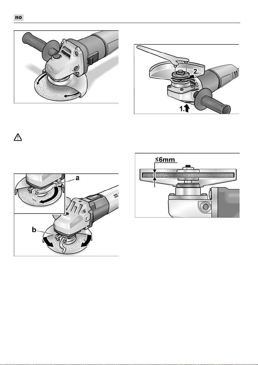
L 3709 -115, L 3709 -125, LE 9-10 125, L 10-10 125, L 801, L 1001
Drei sikkerhetsdekselet til den ønskede
posisjonen.
Hurtigspennhette
(LE 9-10 125, L 10-10 125, L 1001)
ADVARSEL!
Ved skrubb- og skillearbeider må det aldri
arbeides uten deksel.
Trekk ut støpselet.
Løsne spennspaken (a).
Still inn vernehetten.
Festing eller skift av slipeverktøy
Trekk ut støpselet.
Trykk stopperen for spindelen og hold
den stoppet (1.).
Med tappnøkkelen løsnes spennmutte-
ren mot klokkens retning fra spindelen og
tas av (2.).
Legg slipeskiven inn riktig.
Skruen (b) skrues så fast at
spennspaken såvidt kan spennes fast
med hånden.
Skru spennspaken fast igjen.
For skilling må det brukes en spesiell
vernehette for hurtigspenning.
96
Skru spennmutteren på spindelen med
anslaget opp.
Trykk spindellåsen og hold den trykketn.
Fest fast spennmutteren med
tappnøkkelen.
Stikk støpselet inn i stikkontakten.
Slå på vinkelsliperen med bryteren
(uten å låse den fast) og la vinkelsliperen gå i ca. 30 sekunder.
Kontroller den for ujevnheter og vibrasjoner.
Slå vinkelsliperen av.
Page 97
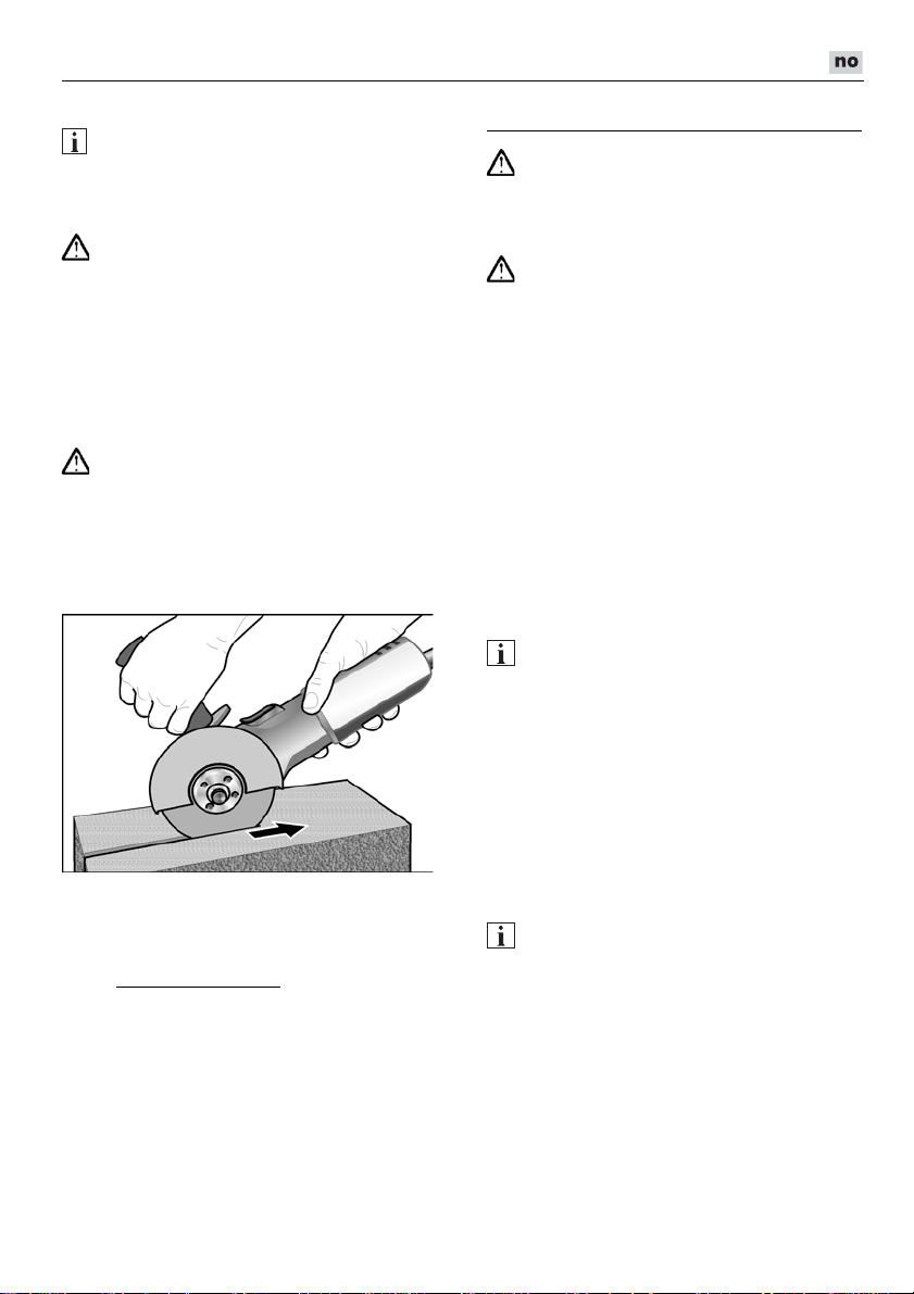
L 3709 -115, L 3709 -125, LE 9-10 125, L 10-10 125, L 801, L 1001
Arbeidstips
HENVISNING
Etter utkopling går slipeverktøyet etter i kort
tid.
Skrubbsliping
ADVARSEL!
Bruk aldri skilleskiver til skrubbsliping.
– Bruk skråvinkel 20–40º for best sliping.
– Bevege vinkelsliperen fram og tilbake
med middels trykk. Dermed blir
arbeidsstykket ikke for varmt og det
oppstår ingen misfarginger; Det oppstår
heller ingen riller.
Skillesliping
ADVARSEL!
For skillesliping må det brukes en spesiell
vernehette for skillesliping.
– Ikke trykk, ikke klem, ikke oscillere.
– Tilpass framdriften til det arbeidsstykket
som skal bearbeides; jo hardere, desto
langsommere må det arbeides.
– Vinkelsliperen må alltid arbeide i motløp.
Ellers oppstår det fare for at den springer
ukontrollert ut av rillen.
Videre informasjoner om produktene finnes
under www.flex-tools.com.
Vedlikehold og pleie
ADVARSEL!
Før alle arbeider med vinkelsliperen må
strømkabelen trekkes ut.
Rengjøring
ADVARSEL!
Ved bearbeiding av metaller kan det ved
ekstrem innsats avleires ledende støv
på innsiden av kapslingen.
Dette kan ha innvirkning på beskyttelsesisolasjonen! Maskinen må derfor drives via
en feilstrømbryter (utløsningsstrøm 30 mA).
Apparatet og ventilasjonssprekkene
må rengjøres regelmessig.
Hvor ofte dette må skje er avhengig av hvor
lenge maskinen er i bruk.
Innsiden av kassen med motoren må
regelmessig blåses ut med tørr trykkluft.
Kullbørster
Vinkelsliperen er utstyrt med utkoplingskull.
Når slitasjegrensen til utkoplingskullene er
nådd, blir vinkelsliperen automatisk slått av.
HENVISNING
For utskifting må det kun brukes originaldeler fra produsenten. Ved bruk av andre
fabrikater, gjelder ikke garantien fra produsentens side.
Igjennom luftinntaksåpningen bak kan
kullfyret kontrolleres under bruken.
Ved sterkt kullfyr, må vinkelsliperen slås av.
Vinkelsliperen må leveres inn på et kundeservice verksted som er autorisert av produsenten.
Drevet
HENVISNING
Skruen på drivhodet må ikke løsnes
i garantitiden. Dersom dette ikke blir fulgt,
slettes produsentens garantiforpliktelser.
Reparasjoner
Reparasjoner må utelukkende utføres
av et kundeserviceverksted som er autorisert av produsenten.
97
Page 98

L 3709 -115, L 3709 -125, LE 9-10 125, L 10-10 125, L 801, L 1001
Klaus Peter Weinper
Head of Quality
Department (QD)
Eckhard Rhle
Manager Research &
Development (R & D)
Reservedeler og tilbehør
Videre tilbehør, særlig slipeverktøy finnes
i katalogen til produsenten.
Eksplosjonstegninger og lister for reservedeler finnes på vår hjemmeside:
www.flex-tools.com
Henvisninger om skroting
ADVARSEL!
Utrangerte maskiner må gjøres ubrukelige
ved å fjerne strømkabelen.
Kun for EU-land
Ikke kast elektrisk verktøy i bosset.
I henhold til det europeiske direktivet
2012/19/EF om avhending av elektrisk
og elektronisk gammelt utstyr og omsetting
av nasjonal rett, må brukte elektriske
verktøy samles separat og avhendes på en
miljø-vennlig måte.
HENVISNING
Faghandelen vil gi deg informasjon
om avhendingsmåter.
-Konformitet
Vi erklærer hermed at vi alene er ansvarlig
for at de punkter som er beskrevet under
„Tekniske data“ stemmer overens med
følgende normer eller normative
dokumenter:
EN 60745 i henhold til bestemmelsene
i direktivene 2014/30/EF, 2006/42/EF,
2011/65/EF.
Ansvarlig for tekniske dokumenter:
FLEX-Elektrowerkzeuge GmbH, R & D
Bahnhofstrasse 15, D-71711 Steinheim/Murr
Utelukkelse av ansvar
Produsenten og hans representant er ikke
ansvarlige for skader eller tapt vinning på
grunn av avbrytelser i driften som er
forårsaket av produktet og ikke mulig bruk
av produktet.
Produsenten og hans representant er ikke
ansvarlige for skader som er forårsaket av
ikke forskriftsmessig bruk av eller i
forbindelse med produkter fra andre
produsenter.
16.06.2016; FLEX-Elektrowerkzeuge GmbH
Bahnhofstrasse 15, D-71711 Steinheim/Murr
98
Page 99
L 3709 -115, L 3709 -125, LE 9-10 125, L 10-10 125, L 801, L 1001
Innehåll
Teckenförklaring . . . . . . . . . . . . . . . . . . 99
Tecken på maskinen . . . . . . . . . . . . . . . 99
Tekniska data . . . . . . . . . . . . . . . . . . . 103
Översikt . . . . . . . . . . . . . . . . . . . . . . . . 104
För din säkerhet . . . . . . . . . . . . . . . . . . 99
Buller och vibration . . . . . . . . . . . . . . . 102
Bruksanvisning . . . . . . . . . . . . . . . . . . 103
Underhåll . . . . . . . . . . . . . . . . . . . . . . . 107
Skrotning och avfallshantering . . . . . . 108
-Försäkran om överensstämmelse . 108
Ansvar . . . . . . . . . . . . . . . . . . . . . . . . . 108
Teckenförklaring
VARNING!
Varnar för en omedelbart hotande fara!
Risk för liv och lem om varningen ej
beaktas.
VAR FÖRSIKTIG!
Varnar för en möjlig farlig situation.
Om varningen ej beaktas kan person- eller
sakskador uppstå.
OBS
Hänvisar till tips och viktig information.
Tecken på maskinen
Läs bruksanvisningen innan
maskinen tas bruk!
Använd skyddsglasögon!
Skyddsklass II
(fullständigt isolerad)
Skrotningsanvisning för den gamla
maskinen (se sida 108)!
För din säkerhet
Läs igenom och beakta:
–
–
–
Denna vinkelslipmaskin är konstruerad
enligt modern teknik och allmänt erkända
säkerhets-tekniska regler. Trots det kan fara
för liv och lem liksom för maskinen eller
andra föremål uppstå. Vinkelslipmaskinen
får endast användas
–
–
Störningar som kan påverka säkerheten
måste omgående åtgärdas.
Avsedd användning
Denna vinkelslipmaskin är avsedd
– för användning inom industri och
– för torr slipning och kapning av metall och
– för slipning med tillbehör som anges
Ej tillåtet är t.ex. kedjefrässkivor och sågblad.
Säkerhetsanvisningar
Läs igenom alla säkerhetsanvisningar,
instruktioner, illustrationer och
specifikationer som medföljer elverktyget.
Om dessa inte följs kan elektriska stötar,
brand och/eller svåra skador uppstå.
Förvara alla säkerhetsanvisningarna på en
åtkomlig säker plats.
Gemensamma säkerhetsanvisningar
för slipning och kapslipning
VARNING!
föreliggande bruksanvisning,
”Allmänna säkerhetsanvisningar”
för elverktyg i det bifogade häftet
(nr. 315.915),
gällande arbetarskyddsbestämmelser.
för avsett ändamål,
i tekniskt felfritt tillstånd.
hantverk,
sten; för kapning är ett speciellt
sprängskydd nödvändigt,
in denna bruksanvisning eller rekommenderas av tillverkaren och är godkända för en periferihastighet på 80 m/s.
VARNING!
Detta elverktyg är avsett för användning
som slipmaskin och kap-/slipmaskin.
Beakta alla säkerhetsanvisningar,
anvisningar, bilder och data som erhålls
med maskinen.
99
Page 100

L 3709 -115, L 3709 -125, LE 9-10 125, L 10-10 125, L 801, L 1001
Om följande anvisningar ej beaktas kan
elektriska stötar, brand och/eller svåra
personskador uppstå.
Detta elverktyg är ej lämpligt för slipning
med sandpapper, arbete med trådborste
och polering.
Ej avsedd användning av elverktyget kan
förorsaka faror och personskador
Använd aldrig tillbehör som inte är avsett
.
och rekommenderat av tillverkaren
speciellt för detta elverktyg. Bara för att
ett tillbehör kan monteras på elverktyget
garanteras ingen säker användning.
Insatsverktygets tillåtna varvtal måste
vara minst så högt som elverktygets
angivna max varvtal.
Tillbehör som roterar snabbare än tillåtet,
kan gå sönder och flyga omkring.
Insatsverktygets ytterdiameter och tjock-
lek måste motsvara elverktygets angivna
mått. Felaktigt uppmätta insatsverktyg
kan inte skärmas eller kontrolleras
tillräckligt.
Insatsverktyg med gänginsats måste
passa exakt till slipspindelns gänga.
Vid insatsverktyg som monteras med fläns
måste insatsverktygets håldiameter passa
till flänsens infästningsdiameter.
Insatsverktyg som inte passar exakt på
elverktygets slipspindel roterar ojämnt,
vibrerar starkt och kan leda till att kontrollen förloras.
Använd aldrig skadade insatsverktyg.
Kontrollera före varje användning
insatsverktygen som t.ex. slipskivor
avseende splitterskador och sprickor,
sliprondeller avseende sprickor repor
eller kraftig nedslitning, stålborstar
avseende lösa eller brustna trådar.
Kontrollera att elverktyget eller insatsverktyget ej tagit skada om det fallit ner
eller använd ett oskadat insatsverktyg.
När insatsverktyget kontrollerats och
monterats, måste du hålla dig och andra
personer utanför det roterande insatsverktygets plan och låta maskinen
gå en minut med högsta varvtal.
Skadade insatsverktyg bryts oftast redan
under denna testtid.
Använd personlig skyddsutrustning.
Använd beroende på tillämpning ansiktsskydd, ögonskydd eller skyddsglasögon.
Använd vid behov dammfiltermask, hörselskydd, skyddshandskar eller specialförkläde som skyddar mot fina slip- och
materialpartiklar. Ögonen måste
skyddas mot kringflygandefrämmande
partiklar, som uppstår vid olika
tillämpningar. Vid användning måste
damm- eller andningsskyddsmask filtrera
uppstående damm. Om du utsätter dig
länge för starkt buller, kan hörseln ta
skada.
Se till att andra personer håller tillräckligt
avstånd till ditt arbetsområde. Alla som
beträder arbetsområdet måste bära
personlig skyddsutrustning. Brottstycken
från arbetsstycket eller avbrutna
insatsverktyg kan flyga omkring och
förorsaka personskador även utanför det
direkta arbetsområdet.
Håll maskinen under arbete endast
i de isolerade greppytorna om insatsverktyget kan träffa dolda strömledningar
eller den egna nätkabeln.
Kontakt med en strömförande ledning
kan även sätta metallmaskindelar under
spänning och leda till elektriska stötar.
Håll nätkabeln på avstånd från roterande
insatsverktyg.
Om du tappar kontrollen över maskinen,
kan nätkabeln kapas eller gripas och din
hand eller arm komma i kontakt med det
roterande verktyget.
Lägg aldrig ifrån dig elverktyget förrän
insatsverktyget står helt stilla.
Det roterande insatsverktyget kan
komma i kontakt med avläggningsytan,
varigenom du kan tappa kontrollen
över elverktyget.
Låt aldrig elverktyget vara igång
när det bärs.
Din klädsel kan genom tillfällig kontakt
gripas av det roterande insatsverktyget
och insatsverktyget kan borra in sig
i din kropp.
Rengör elverktygets ventilationsspringor
regelbundet.
Motorfläkten suger in damm i huset
och en större mängd metalldamm kan
förorsaka elektriska faror.
Använd ej elverktyget i närheten
av brännbart material.
Gnistor kan tända dessa material.
100
 Loading...