

Page 1
DD 2G 18.0-EC
PD 2G 18.0-EC
IW 1/2" 18.0-EC
ID 1/4" 18.0-EC
Page 2

Originalbetriebsanleitung . . . . . . . . . . . . . . . . . . . . . . . . 3
Original operating instructions . . . . . . . . . . . . . . . . . . . . 17
Notice d’instructions d’origine . . . . . . . . . . . . . . . . . . . . . 30
Istruzioni per l’uso originali . . . . . . . . . . . . . . . . . . . . . . . 44
Instrucciones de funcionamiento originales . . . . . . . . . . 59
Instruções de serviço originais . . . . . . . . . . . . . . . . . . . . 74
Originele gebruiksaanwijzing . . . . . . . . . . . . . . . . . . . . . 89
Originale driftsvejledning . . . . . . . . . . . . . . . . . . . . . . . . 104
Originale driftsanvisningen . . . . . . . . . . . . . . . . . . . . . . . 117
Originalbruksanvisning . . . . . . . . . . . . . . . . . . . . . . . . . . 130
Alkuperäinen käyttöohjekirja . . . . . . . . . . . . . . . . . . . . . . 143
Αυθεντικές οδηγίες χειρισμού . . . . . . . . . . . . . . . . . . . . . 156
Orijinal işletme kılavuzu . . . . . . . . . . . . . . . . . . . . . . . . 171
Instrukcja oryginalna . . . . . . . . . . . . . . . . . . . . . . . . . . . . 184
Eredeti üzemeltetési útmutató . . . . . . . . . . . . . . . . . . . . 199
Originální návod k obsluze . . . . . . . . . . . . . . . . . . . . . . . 213
Originálny návod na obsluhu . . . . . . . . . . . . . . . . . . . . . 227
Originalna uputa za rad . . . . . . . . . . . . . . . . . . . . . . . . 241
Izvirno navodilo za obratovanje . . . . . . . . . . . . . . . . . . 254
Instrucţiuni de funcţionare originale . . . . . . . . . . . . . . . 268
Оригинално упътване за експлоатация . . . . . . . . . . 282
Оригинальная инструкция по эксплуатации . . . . . . . . 297
Originaalkasutusjuhend . . . . . . . . . . . . . . . . . . . . . . . . . 312
Originali naudojimo instrukcija . . . . . . . . . . . . . . . . . . . . 325
Lietošanas pamācības oriģināls . . . . . . . . . . . . . . . . . . . 339
ﺔﻴﻠــــﺻﻷا ﻞﻴﻐــــﺸﺘﻟا تادﺎــــﺷرﻹ ﺔــــﻤﺟﺮﺗ . . . . . . . . . . . . . . . . . . . . 365
Page 3

DD 2G 18.0-EC / PD 2G 18.0-EC / IW 1/2" 18.0-EC / ID 1/4" 18.0-EC
Inhalt
Verwendete Symbole . . . . . . . . . . . . . . . 3
Symbole am Gerät . . . . . . . . . . . . . . . . . 3
Zu Ihrer Sicherheit . . . . . . . . . . . . . . . . . . 3
Geräusch und Vibration . . . . . . . . . . . . . 5
Technische Daten . . . . . . . . . . . . . . . . . . 6
Auf einen Blick . . . . . . . . . . . . . . . . . . . . 7
Gebrauchsanweisung . . . . . . . . . . . . . . . 8
Wartung und Pflege . . . . . . . . . . . . . . . 14
Transport . . . . . . . . . . . . . . . . . . . . . . . . 15
-Konformität . . . . . . . . . . . . . . . . . . . 15
Entsorgungshinweise . . . . . . . . . . . . . . 15
Haftungsausschluss. . . . . . . . . . . . . . . . 16
Verwendete Symbole
WARNUNG!
Bezeichnet eine unmittelbar drohende
Gefahr. Bei Nichtbeachten des Hinweises
drohen Tod oder schwerste Verletzungen.
VORSICHT!
Bezeichnet eine möglicherweise
gefährliche Situation. Bei Nichtbeachten
des Hinweises drohen Verletzungen oder
Sachschäden.
HINWEIS
Bezeichnet Anwendungstips und wichtige
Informationen.
Symbole am Gerät
Vor Inbetriebnahme
Bedienungsanleitung lesen!
Augenschutz tragen!
Kurzschlussfester
Sicherheitstransformator
Schützen Sie den Akku vor Hitze,
z. B. auch vor dauernder Sonneneinstrahlung, und Feuer.
Es besteht Explosionsgefahr.
Akku nicht ins Feuer werfen.
Es besteht Explosionsgefahr.
Gerät ist nur zur Verwendung in
Räumen geeignet. Gerät nicht
dem Regen aussetzen.
Elektrowerkzeug und Akkus in
trockenen Räumen lagern.
Entsorgungshinweise
(siehe Seite 15)!
Zu Ihrer Sicherheit
WARNUNG!
Lesen Sie alle mit dem Elektrowerkzeug
gelieferten Sicherheitshinweise, Anweisun-
gen, Abbildungen und Spezifikationen.
Versäumnisse bei der Einhaltung der
Sicherheitshinweise und Anweisungen
können elektrischen Schlag, Brand und/oder
schwere Verletzungen zur Folge haben
Bewahren Sie alle Sicherheitshinweise und
Anweisungen für die Zukunft auf.
Vor Gebrauch des Elektrowerkzeuges lesen
und danach handeln:
–
die vorliegende Bedienungsanleitung,
–
die „Allgemeinen Sicherheitshinweise“
zum Umgang mit Elektrowerkzeugen im
beigelegten Heft (Schriften
–
die für den Einsatzort geltenden Regeln
-
Nr.: 315.915),
und Vorschriften zur Unfallverhütung.
Dieses Elektrowerkzeug ist nach dem Stand
der Technik und den anerkannten
sicherheitstechnischen Regeln gebaut.
Dennoch können bei seinem Gebrauch
Gefahren für Leib und Leben des Benutzers
oder Dritter bzw. Schäden an der Maschine
oder an anderen Sachwerten entstehen.
Das Elektrowerkzeug ist nur zu benutzen
–
für die bestimmungsgemäße
Verwendung,
–
in sicherheitstechnisch einwandfreiem
Zustand.
Die Sicherheit beeinträchtigende Störungen
sind umgehend zu beseitigen.
.
3
Page 4

DD 2G 18.0-EC / PD 2G 18.0-EC / IW 1/2" 18.0-EC / ID 1/4" 18.0-EC
Bestimmungsgemäße Verwendung
Der Akku-Bohrschrauber DD 2G 18.0-EC
ist bestimmt
– für den gewerblichen Einsatz in Industrie
und Handwerk,
– zum Eindrehen und Lösen von Schrauben,
– zum Bohren in Holz, Metall, Keramik und
Kunststoff.
Der Akku-Schlagbohrschrauber
PD 2G 18.0-EC ist bestimmt
– für den gewerblichen Einsatz in Industrie
und Handwerk,
– zum Eindrehen und Lösen von Schrauben,
– zum Bohren in Holz, Metall, Keramik und
Kunststoff,
– zum Schlagbohren in Ziegel, Mauerwerk
und Gestein.
Der Akku-Schlagschrauber IW 1/2" 18.0-EC /
ID 1/4" 18.0-EC ist bestimmt
– für den gewerblichen Einsatz in Industrie
und Handwerk,
– zum Anziehen und Lösen von Muttern
und Schrauben in den angegebenen
Abmessungen.
Sicherheitshinweise für
Bohrmaschinen und Schrauber
Halten Sie das Gerät an den isolierten
Griffflächen, wenn Sie Arbeiten ausführen, bei denen das Einsatzwerkzeug
oder die Schraube verborgene Stromleitungen oder das eigene Netzkabel
treffen kann. Der Kontakt der Schraube
mit einer spannungsführenden Leitung
kann auch metallene Geräteteile unter
Spannung setzen und zu einem
elektrischen Schlag führen.
Benutzen Sie Zusatzgriffe, wenn diese
mit dem Elektrowerkzeug mitgeliefert
werden. Der Verlust der Kontrolle kann
zu Verletzungen führen.
Verwenden Sie geeignete Suchgeräte,
um verborgene Versorgungsleitungen
aufzuspüren, oder ziehen Sie die örtliche
Versorgungsgesellschaft hinzu. Kontakt
mit Elektroleitungen kann zu Feuer und
elektrischem Schlag führen. Beschädigung
einer Gasleitung kann zur Explosion
führen. Eindringen in eine Wasserleitung
verursacht Sachbeschädigung.
Schalten Sie das Elektrowerkzeug sofort
aus, wenn das Einsatzwerkzeug
blockiert. Seien Sie auf hohe Reaktions-
momente gefasst, die einen Rückschlag
verursachen.
Das Einsatzwerkzeug blockiert, wenn:
– das Elektrowerkzeug überlastet wird
oder
– es im zu bearbeitenden Werkstück
verkantet.
Halten Sie das Elektrowerkzeug gut fest.
Beim Festziehen und Lösen von
Schrauben können kurzfristig hohe
Reaktionsmomente auftreten.
Sichern Sie das Werkstück. Ein mit
Spannvorrichtungen oder Schraubstock
festgehaltenes Werkstück ist sicherer
gehalten als mit Ihrer Hand.
Warten Sie, bis das Elektrowerkzeug
zum Stillstand gekommen ist, bevor Sie
es ablegen. Das Einsatzwerkzeug kann
sich verhaken und zum Verlust der Kontrolle über das Elektrowerkzeug führen.
Verwenden Sie nur Original-Akkus mit
der auf dem Typenschild Ihres Elektrowerkzeugs angegebenen Spannung.
Bei Gebrauch anderer Akkus, z.B. Nachahmungen, aufgearbeiteter Akkus oder
Fremdfabrikaten, besteht die Gefahr von
Verletzungen sowie Sachschäden durch
explodierende Akkus.
Zusätzlicher Sicherheitshinweis für
Schlagbohrschrauber (PD...)
Tragen Sie Gehörschutz beim Schlag-
bohren. Die Einwirkung von Lärm kann
Gehörverlust bewirken.
Sicherheitshinweise zum Umgang
mit Akkus
Öffnen Sie den Akku nicht. Es besteht die
Gefahr eines Kurzschlusses.
Schützen Sie den Akku vor Hitze, z. B.
auch vor dauernder Sonneneinstrahlung,
Feuer, Wasser und Feuchtigkeit.
Es besteht Explosionsgefahr.
Bei Beschädigung und unsachgemäßem
Gebrauch des Akkus können Dämpfe austreten. Führen Sie Frischluft zu und suchen
Sie bei Beschwerden einen Arzt auf. Die
Dämpfe können die Atemwege reizen.
Bei falscher Anwendung kann Flüssigkeit
aus dem Akku austreten. Vermeiden Sie
den Kontakt damit. Bei zufälligem Kontakt
mit Wasser abspülen. Wenn die Flüssigkeit in die Augen kommt, nehmen Sie
4
Page 5
DD 2G 18.0-EC / PD 2G 18.0-EC / IW 1/2" 18.0-EC / ID 1/4" 18.0-EC
zusätzlich ärztliche Hilfe in Anspruch.
Austretende Akkuflüssigkeit kann zu Hautreizungen oder Verbrennungen führen.
Laden Sie die Akkus nur mit Ladegeräten
auf, die vom Hersteller empfohlen werden.
Durch ein Ladegerät, das für eine bestimmte Art von Akkus geeignet ist, besteht
Brandgefahr, wenn es mit anderen Akkus
verwendet wird.
Durch spitze Gegenstände wie z. B. Nagel
oder Schraubenzieher oder durch äußere
Krafteinwirkung kann der Akku beschädigt
werden. Es kann zu einem internen Kurzschluss kommen und der Akku brennen,
rauchen, explodieren oder überhitzen.
Ladegerät
Überprüfen Sie immer, ob die Netz-
spannung der auf dem Typenschild des
Ladegeräts angegebenen Spannung
entspricht.
Der Anschlussstecker des Ladegerätes
muss in die Steckdose passen. Der
Stecker darf in keiner Weise verändert
werden. Verwenden Sie keine Adapterstecker gemeinsam mit schutzgeerdeten
Elektrowerkzeugen. Unveränderte
Stecker und passende Steckdosen
verringern das Risiko eines elektrischen
Schlages.
Setzen Sie das Ladegerät nur in trocke-
nen Räumen ein und vermeiden Sie den
Kontakt mit Nässe und Regen.
Das Eindringen von Wasser in das
Ladegerät erhöht das Risiko eines
elektrischen Schlags.
Benutzen Sie niemals das Ladegerät,
wenn Kabel, Stecker oder das Gerät
selbst durch äußerliche Einwirkungen
beschädigt sind. Bringen Sie das
Ladegerät zur nächsten Fachwerkstatt.
Öffnen Sie auf keinen Fall das Lade-
gerät. Bringen Sie es im Fall einer Störung
in eine Fachwerkstatt.
Legen Sie keine Gegenstände auf das
Ladegerät und stellen Sie es nicht auf
weichen Oberflächen ab. Es besteht
Brandgefahr.
Spezielle Sicherheitshinweise
Vor allen Arbeiten am Elektrowerkzeug
Drehrichtungsvorwahl-Schalter (2) in
Mittelstellung stellen.
Drehrichtungsvorwahl-Schalter (2) bzw.
Drehmomenteneinstellung (5) nur bei
stillstehendem Werkzeug betätigen.
Zur Kennzeichnung des Elektro-
werkzeugs nur Klebschilder verwenden.
Keine Löcher in das Gehäuse bohren.
Geräusch und Vibration
HINWEIS
Die Geräusch- und Schwingungswerte
wurden entsprechend EN 62841 ermittelt.
Die Werte finden Sie in der Tabelle
„Technische Daten“.
VORSICHT!
Die angegebenen Messwerte gelten für neue
Geräte. Im täglichen Einsatz verändern sich
Geräusch- und Schwingungswerte.
HINWEIS
Der in diesen Anweisungen angegebene
Schwingungspegel ist entsprechend einem in
EN 62841 genormten Messverfahren gemessen worden und kann für den Vergleich von
Elektrowerkzeugen miteinander verwendet
werden. Er eignet sich auch für eine vorläufige
Einschätzung der Schwingungsbelastung.
Der angegebene Schwingungspegel repräsentiert die hauptsächlichen Anwendungen
des Elektrowerkzeugs. Wenn allerdings das
Elektrowerkzeug für andere Anwendungen,
mit abweichenden Einsatzwerkzeugen oder
ungenügender Wartung eingesetzt wird, kann
der Schwingungspegel abweichen. Dies kann
die Schwingungsbelastung über den gesamten Arbeitszeitraum deutlich erhöhen.
Für eine genaue Abschätzung der Schwingungsbelastung sollten auch die Zeiten
berücksichtigt werden, in denen das Gerät
abgeschaltet ist oder zwar läuft, aber nicht
tatsächlich im Einsatz ist. Dies kann die
Schwingungsbelastung über den gesamten
Arbeitszeitraum deutlich reduzieren.
Legen Sie zusätzliche Sicherheitsmaßnahmen zum Schutz des Bedieners vor der
Wirkung von Schwingungen fest wie zum
Beispiel: Wartung von Elektrowerkzeug und
Einsatzwerkzeugen, Warmhalten der Hände,
Organisation der Arbeitsabläufe.
VORSICHT!
Bei einem Schalldruck über 85 dB(A)
Gehörschutz tragen.
5
Page 6

Technische Daten
DD 2G 18.0-EC / PD 2G 18.0-EC / IW 1/2" 18.0-EC / ID 1/4" 18.0-EC
Gerät DD 2G
18.0-EC
Bohr-
Typ
schrauber
PD 2G
18.0-EC
Schlag-
bohr-
IW 1/2"
18.0-EC
Schlag-
schrauber
schrauber
Akku AP 18.0/2,5
AP 18.0/5,0
Ladezeit (je nach Ladezustand)
– AP 18.0/2,5
– AP 18.0/5,0
min
min
0–40
0–45
Drehmoment, maximal
– weicher Schraubfall
– harter Schraubfall
Nm
Nm
56
90
56
90
–
250
Drehmomentstufen 20 24 –
Leerlaufdrehzahl
– Stufe 1
– Stufe 2
– Stufe 3
min
min
min
-1
-1
-1
0...600
0...2300
–
0...600
0...2300
–
1500
2000
2500
Schlagzahl
– Stufe 1
– Stufe 2
– Stufe 3
min
min
min
-1
-1
-1
–
–
–
0...9600
0...37000
–
1300
2800
3300
Bohrfutter mm 1,5–13 –
Max. Bohrdurchmesser
– in Holz
– in Stahl
– im Mauerwerk
Gewicht entsprechend „EPTA-
procedure 01/2003“ (ohne Akku)
Gewicht Akku 2,5 Ah
Gewicht Akku 5,0 Ah
mm
mm
mm
60
13
16
60
13
16
–
–
–
kg 1,5 1,6 1,1 1,1
kg
kg
0,4
0,7
A-bewerteter Schalldruckpegel
Schalldruckpegel L
pA
Schallleistungspegel L
WA
dB(A) 78* 78* / 95** 91*** 91***
dB(A) 89* 89* / 106** 102*** 102***
Unsicherheit K db 3,0
Schwingungsgesamtwerte (Vektorsumme dreier Richtungen)
Schwingungsemissionswert a
– Bohren in Metall
– Schlagbohren in Beton
– Schrauben
Unsicherheit K
* Bohren in Metall / ** Schlagbohren in Beton / *** Schlagschrauben
beim ....
h
m/s
m/s
m/s
m/s
2
<2,5 <2,5 – –
2
2
2
– 15,5 – –
<2,5 <2,5 18,5*** 18,5***
1,5
ID 1/4"
18.0-EC
Schlag-
schrauber
–
225
1500
2000
2500
1300
2800
3300
–
–
–
6
Page 7

DD 2G 18.0-EC / PD 2G 18.0-EC / IW 1/2" 18.0-EC / ID 1/4" 18.0-EC
Auf einen Blick
In dieser Anleitung werden verschiedene Elektrowerkzeuge beschrieben. Die Darstellung
kann im Detail vom erworbenen Elektrowerkzeug abweichen.
1 Schalter
Zum Ein- und Ausschalten sowie zum
Hochfahren bis zur maximalen Drehzahl
2 Drehrichtungsvorwahl-Schalter
3 Geschwindigkeits-Wahlschalter
4 Drehring für Betriebsart (nur PD ...)
5 Drehring für Drehmomenteinstellung
6 Werkzeugaufnahme
7 Arbeitsplatzbeleuchtung
8 Handgriff
9 Bedienfeld Drehzahlstufen
10 Einschubschacht für Akku
11 Winkelvorsatz mit Entriegelungsring
12 Wechselbohrfutter mit
Entriegelungsring
13 Bithaltervorsatz mit Entriegelungsring
14 Zusatzhandgriff
15 Li-Ion-Akku (2,5 Ah)
16 Entriegelungstaste für Akku
17 Akkuzustands-Anzeige
18 Li-Ion-Akku (5,0 Ah)
19 Gürtelklammer
20 Befestigungsschraube
21 Bit-Halter
7
Page 8
DD 2G 18.0-EC / PD 2G 18.0-EC / IW 1/2" 18.0-EC / ID 1/4" 18.0-EC
Gebrauchsanweisung
Vor der Inbetriebnahme
Elektrowerkzeug und Zubehör
auspacken und auf Vollständigkeit der
Lieferung und Transportschäden
kontrollieren.
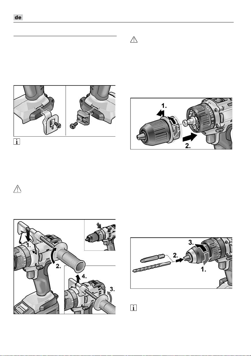
Gürtelklammer bzw. Bit-Halter mit
beiliegender Schraube befestigen.
HINWEIS
Die Akkus sind bei Lieferung nicht vollständig geladen. Vor dem ersten Betrieb
die Akkus vollständig laden. Siehe dazu
„Ladegerät/Ladevorgang“.
Zusatzhandgriff montieren/
demontieren (PD/DD 2G 18.0-EC)
VORSICHT!
Benutzen Sie Zusatzgriffe, wenn diese mit
dem Elektrowerkzeug mitgeliefert werden.
Der Verlust der Kontrolle kann zu
Verletzungen führen.
Wechselbohrfutter BF 18.0-EC
VORSICHT!
Vor allen Arbeiten am Elektrowerkzeug
Drehrichtungsvorwahl-Schalter (2) in
Mittelstellung stellen.
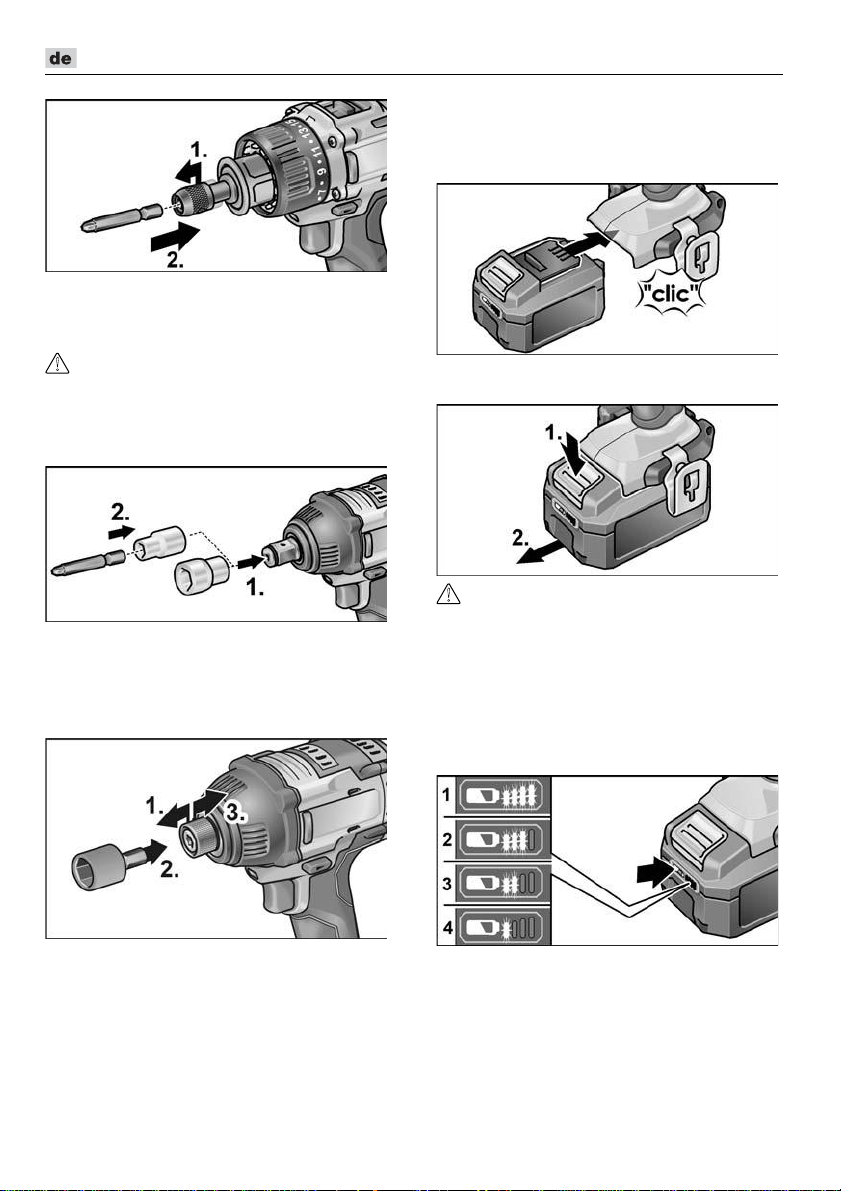
Montieren
Entriegelungsring nach vorn ziehen (1.)
und Wechselbohrfutter bis zum Anschlag
auf die Werkzeugaufnahme drücken (2.).
Entriegelungsring loslassen. Einrastung
des Bohrfutters kontrollieren.
Demontieren
Entriegelungsring nach vorn ziehen und
Bohrfutter abnehmen.
Einsetzen der Werkzeuge
Im Bohrfutter werden Bohrer mit einem
Durchmesser von 1,5–13 mm, Schrauberbits
½" sowie Bithalter ½" sicher gehalten.
Elektrowerkzeug mit einer Hand
festhalten und das Bohrfutter mit der
anderen Hand drehen.
– Gegen den Uhrzeigersinn drehen,
um das Bohrfutter weiter zu öffnen.
– Im Uhrzeigersinn drehen, um das
Bohrfutter zu schließen.
Werkzeug einsetzen.
Bohrfutter vollständig schließen.
HINWEIS
Probelauf durchführen, um die zentrische
Einspannung der Werkzeuge zu prüfen.
8
Page 9
DD 2G 18.0-EC / PD 2G 18.0-EC / IW 1/2" 18.0-EC / ID 1/4" 18.0-EC
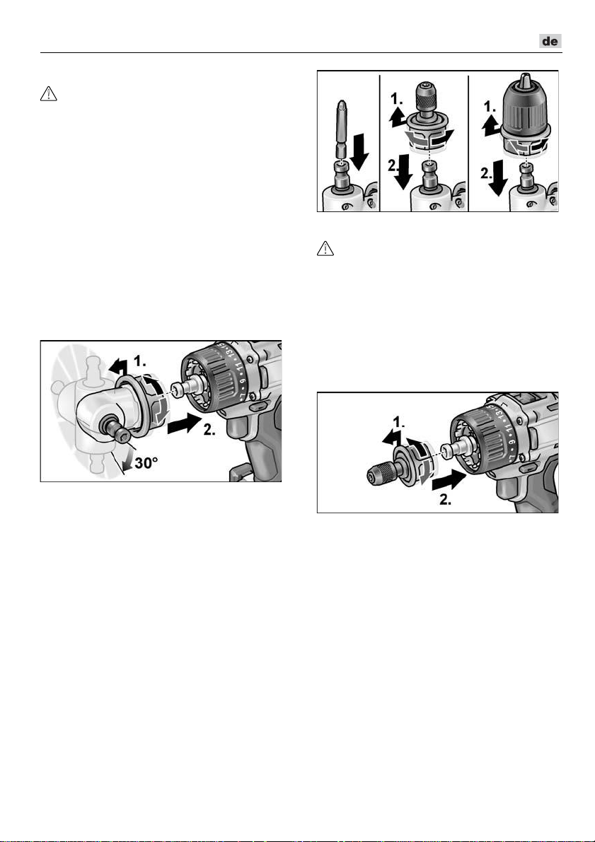
Winkelvorsatz WV 18.0-EC
VORSICHT!
Vor allen Arbeiten am Elektrowerkzeug
Drehrichtungsvorwahl-Schalter (2) in
Mittelstellung stellen.
Der Winkelvorsatz erleichtert das Arbeiten
an schwer zugänglichen Stellen.
Der Winkelvorsatz lässt sich in verschiedenen Winkelstellungen jeweils 30° versetzt
einrasten.
Montieren
Entriegelungsring nach vorn ziehen (1.)
und Winkelvorsatz bis zum Anschlag auf
die Werkzeugaufnahme drücken (2.).
Winkelvorsatz in der gewünschten
Winkelstellung einrasten lassen.
Entriegelungsring loslassen. Einrastung
kontrollieren.
Bithaltervorsatz BV 18.0-EC
VORSICHT!
Vor allen Arbeiten am Elektrowerkzeug
Drehrichtungsvorwahl-Schalter (2) in
Mittelstellung stellen.
Montieren
Entriegelungsring nach vorn ziehen (1.)
und Bithaltervorsatz bis zum Anschlag
auf die Werkzeugaufnahme drücken (2.).
Entriegelungsring loslassen. Einrastung
kontrollieren.
Demontieren
Entriegelungsring nach vorn ziehen und
Winkelvorsatz abnehmen.
Einsetzen der Werkzeuge
Der Winkelvorsatz verfügt über eine
½" Werkzeugaufnahme. In der
Werkzeugaufnahme werden Schrauberbits
sowie Bithalter sicher gehalten.
Auf dem Winkelvorsatz kann auch das
Wechselbohrfutter (siehe „Wechselbohrfutter BF 18.0-EC“) oder der Bithalter (siehe
„Bithaltervorsatz BV 18.0-EC“) montiert
werden.
Demontieren
Entriegelungsring nach vorn ziehen und
Bithaltervorsatz abnehmen.
Einsetzen der Werkzeuge
Der Bithaltervorsatz verfügt über eine
½" Werkzeugaufnahme. In der Werkzeug-
aufnahme werden Schrauberbits sicher
gehalten.
Werkzeugarretierung nach vorn zie-
hen (1.) und das Werkzeug bis zum
Anschlag eindrücken (2.).
Werkzeugarretierung loslassen.
9
Page 10
DD 2G 18.0-EC / PD 2G 18.0-EC / IW 1/2" 18.0-EC / ID 1/4" 18.0-EC
Zum Entnehmen der Werkzeuge
Werkzeugarretierung nach hinten ziehen.
Werkzeugwechsel
VORSICHT!
Vor allen Arbeiten am Elektrowerkzeug
Drehrichtungsvorwahl-Schalter (2) in
Mittelstellung stellen.
IW 1/2“ 18.0-EC:
Steckschlüssel auf Vierkantvorsatz
des Schlagschraubers drücken (1.).
Werkzeug in Steckschlüssel
einsetzen (2.).
ID 1/4“ 18.0-EC:
Akku einsetzen/wechseln
Geladenen Akku bis zum vollständigen
Einrasten in das Elektrowerkzeug
eindrücken.
Zum Entnehmen die Entriegelungstasten
drücken (1.) und Akku herausziehen (2.).
VORSICHT!
Bei Nichtgebrauch die Kontakte des Akkus
schützen. Lose Metallteile können die
Kontakte kurzschließen, es besteht
Explosions- und Brandgefahr!
Ladezustand des Akkus
Durch Drücken der Taste kann an den
LED‘s der Akkuzustands-Anzeige der
Ladezustand geprüft werden.
Werkzeugarretierung nach vorn
ziehen (1.) und das Werkzeug bis zum
Anschlag eindrücken (2.).
Werkzeugarretierung loslassen.
Zum Entnehmen der Werkzeuge
Werkzeugarretierung nach hinten
ziehen (3.).
10
Die Anzeige erlischt nach 5 Sekunden.
Blinkt eine der LED‘s, muss der Akku
geladen werden. Wenn nach dem Drücken
der Taste keine LED leuchtet, ist der Akku
defekt und muss ersetzt werden.
Page 11
DD 2G 18.0-EC / PD 2G 18.0-EC / IW 1/2" 18.0-EC / ID 1/4" 18.0-EC
Drehrichtungsvorwahl
VORSICHT!
Drehrichtung nur bei Stillstand des
Elektrowerkzeugs ändern.
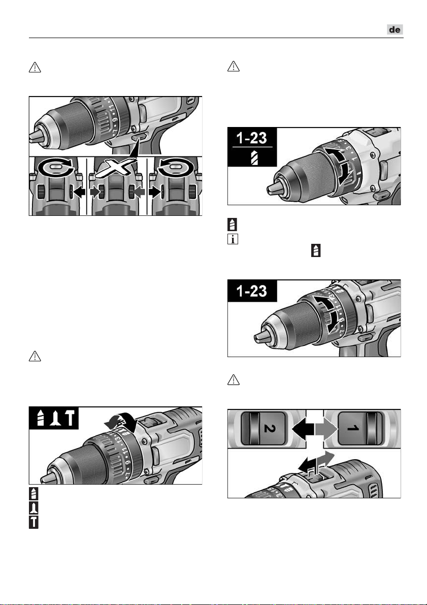
Drehrichtungsvorwahl-Schalter auf die
benötigte Position stellen:
– Links: gegen den Uhrzeigersinn
(Schrauben herausdrehen, Schrauben
lösen)
– Rechts: im Uhrzeigersinn
(Bohren, Schrauben eindrehen,
Schrauben festziehen)
– Mitte: Einschaltsperre
(Werkzeugwechsel, bei allen Arbeiten
am Elektrowerkzeug)
Betriebsart (nur PD 2G 18.0-EC)
VORSICHT!
Betriebsart nur bei Stillstand des
Elektrowerkzeugs ändern.
Drehring für Betriebsart auf die benötigte
Position stellen.
Drehmomentvorwahl
VORSICHT!
Drehmoment nur bei Stillstand des
Elektrowerkzeugs ändern.
Drehring für Drehmomenteinstellung auf
die benötigte Position stellen.
DD 2G 18.0-EC:
1–23: Schrauben
: Bohren
HINWEIS
In der Bohr-Stellung ist die Rutschkupplung deaktiviert.
PD 2G 18.0-EC:
Geschwindigkeitsvorwahl
VORSICHT!
Geschwindigkeit nur bei Stillstand des
Elektrowerkzeugs ändern.
: Bohren
: Schrauben
: Schlagbohren
Wahlschalter auf die benötigte Stufe stellen:
1: langsame Geschwindigkeit,
hohes Drehmoment
2: schnelle Geschwindigkeit,
niedriges Drehmoment
11
Page 12
DD 2G 18.0-EC / PD 2G 18.0-EC / IW 1/2" 18.0-EC / ID 1/4" 18.0-EC
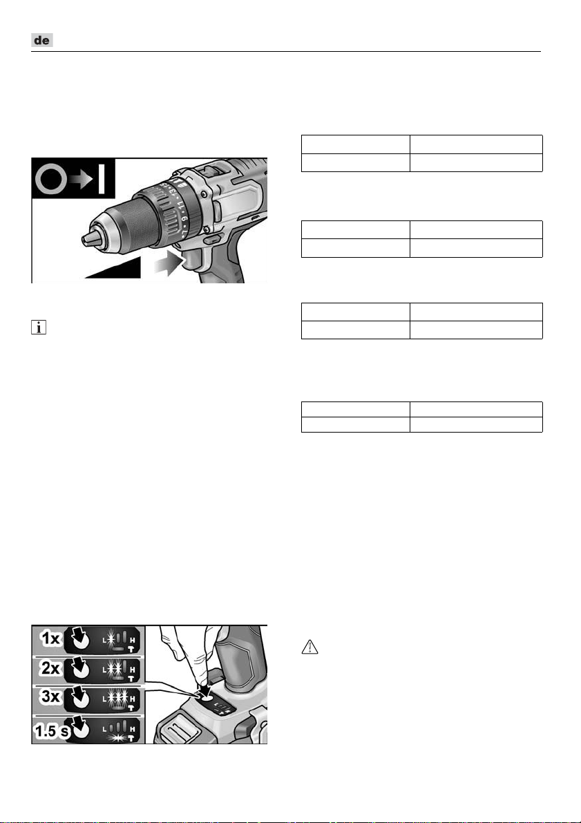
Elektrowerkzeug einschalten
Gerät einschalten:
Schalter drücken.
Der Schalter des Elektrowerkzeugs
ermöglicht ein stufenweises Steigern
der Drehzahl bis zum Maximalwert.
Gerät ausschalten:
Schalter loslassen.
HINWEIS
–
Das Elektrowerkzeug verfügt über eine
Bremse, die das Einsatzwerkzeug sofort
nach Loslassen des Schalters stoppt.
–
Bei dauerhaftem Einsatz des Elektrowerkzeugs sollte hauptsächlich mit voll durchgedrücktem Schalter gearbeitet werden.
Arbeitsplatzbeleuchtung ein-/
ausschalten
1. Drehrichtungsvorwahl-Schalter (2) in
Stellung „Vorwärts“ oder „Rückwärts“
schalten.
2. Ein-/Ausschalter (1) Elektrowerkzeug
drücken
– Arbeitsplatzbeleuchtung leuchtet
3. Ein-/Ausschalter (1) Elektrowerkzeug
loslassen
– Arbeitsplatzbeleuchtung erlischt
automatisch nach ca. 10 s
Drehzahl- und Drehmomentenvorwahl
IW 1/2“ 18.0-EC / ID 1/4“ 18.0-EC
Drehzahl-/Drehmoment umschalten
1. Ein-/Ausschalter (1) einschalten
2. Modusschalter kurz drücken (ca. 0,5 s).
– Eine LED leuchtet – Drehmoment:
IW 1/2“ 18.0-EC:
ID 1/4“ 18.0-EC:
3. Modusschalter kurz drücken
– Zwei LED‘s leuchten – Drehmoment:
IW 1/2“ 18.0-EC:
ID 1/4“ 18.0-EC:
4. Modusschalter kurz drücken
– Drei LED‘s leuchten – Drehmoment:
IW 1/2“ 18.0-EC:
ID 1/4“ 18.0-EC:
5. Modusschalter kurz drücken
– Eine LED leuchtet – Drehmoment
schaltet zurück auf:
IW 1/2“ 18.0-EC: 150 Nm
ID 1/4“ 18.0-EC: 60 Nm
Drehmoment kann wie beschrieben wieder
hochgeschaltet werden.
Im Rückwärtslauf des Elektrowerkzeugs –
hat nur eine Drehzahl – erlöschen die im
Fuß befindlichen LED‘s automatisch.
150 Nm / 1500 min
60 Nm / 1500 min
180 Nm / 2000 min
105 Nm / 2000 min
250 Nm / 2500 min
225 Nm / 2500 min
-1
-1
-1
-1
-1
-1
Einzelschlag-Modus in
Schlagschrauber-Modus umschalten
Modusschalter ca. 1,5 s drücken.
– LED-Modusanzeige leuchtet –
Einzelschlag-Modus aktiv
– LED-Modusanzeige leuchtet nicht –
Schlagschrauber-Modus aktiv.
Arbeiten mit dem Elektrowerkzeug
VORSICHT!
Vor allen Arbeiten am Elektrowerkzeug
Drehrichtungsvorwahl-Schalter (2) in
Mittelstellung stellen.
12
Page 13
DD 2G 18.0-EC / PD 2G 18.0-EC / IW 1/2" 18.0-EC / ID 1/4" 18.0-EC
HINWEIS
Damit die Handhabung beim Schrauben
leichter wird, kann der Schrauberbit auch
direkt in die Werkzeugaufnahme des
Gerätes eingesetzt werden.
1. Werkzeugträger (Wechselbohrfutter,
Winkelvorsatz, Bithaltervorsatz)
montieren.
2. Akku einsetzen.
3. Werkzeug (Bohrer, Schrauberbits,
Bithalter) einsetzen.
4. Betriebsart entsprechend der Arbeits-
aufgabe einstellen (nur PD...).
5. Drehmomentvorwahl auf die benötigte
Stufe stellen.
6. Geschwindigkeit auf die benötigte Stufe
stellen.
7. Benötigte Drehrichtung einstellen.
8. Elektrowerkzeug mit einer Hand am
Handgriff ergreifen und Arbeitsposition
einnehmen.
Bei laufendem Motor niemals den
Drehrichtungsvorwahl-Schalter bzw.
Drehmomenteneinstellung betätigen!
9. Gerät einschalten.
Nach Arbeitsende:
10. Schalter loslassen.
11. Drehrichtungsvorwahl-Schalter (2) in
Mittelstellung stellen.
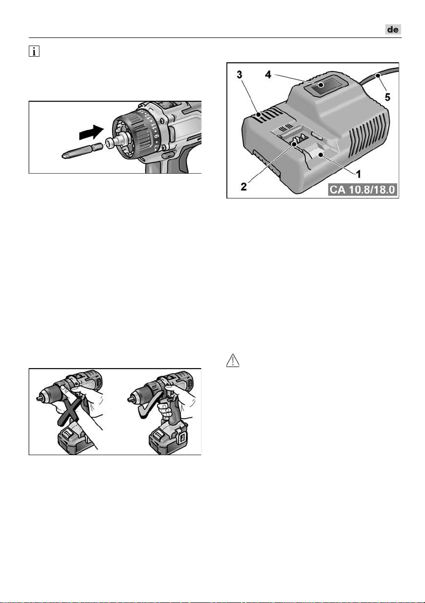
Ladegerät
1 Einschubschacht für Akku
2 Kontakte
3 Lüftungsschlitze
4 Display zur Anzeige des
Betriebszustandes
5 Netzkabel mit Netzstecker
Das Ladegerät CA 10.8/18.0 ist bestimmt
zum Laden von FLEX-Akkus der Typen
– AP 10.8 (2,5 Ah),
– AP 18.0 (2,5 Ah),
– AP 10.8 (5,0 Ah),
– AP 18.0 (5,0 Ah).
Hinweise für eine lange AkkuLebensdauer
VORSICHT!
–
Akkus niemals bei Temperaturen unter
0 °C bzw. über 55 °C laden.
–
Akkus nicht in Umgebung mit hoher
Luftfeuchtigkeit oder Umgebungstemperatur laden.
–
Akkus und Ladegerät während des
Ladevorgangs nicht bedecken.
–
Netzstecker des Ladegeräts nach Ende
des Ladevorgangs ziehen.
Während des Ladevorgangs erwärmen sich
Akku und Ladegerät. Das ist normal!
Lithium-Ionen-Akkus weisen nicht den
bekannten „Memory-Effekt“ auf. Trotzdem
sollte ein Akku vor dem Aufladen vollständig
entladen werden und der Ladevorgang immer
vollständig abgeschlossen werden.
Werden die Akkus längere Zeit nicht benutzt,
Akkus teilweise geladen und kühl lagern.
13
Page 14
DD 2G 18.0-EC / PD 2G 18.0-EC / IW 1/2" 18.0-EC / ID 1/4" 18.0-EC
Ladevorgang
VORSICHT!
Nur Originalakkus in das mitgelieferte
Ladegerät einsetzen.
Netzstecker des Ladegeräts einstecken.
Die Hintergrundbeleuchtung des Displays
leuchtet für 2 Sekunden grün und verlischt
dann wieder. Es wird OK angezeigt.
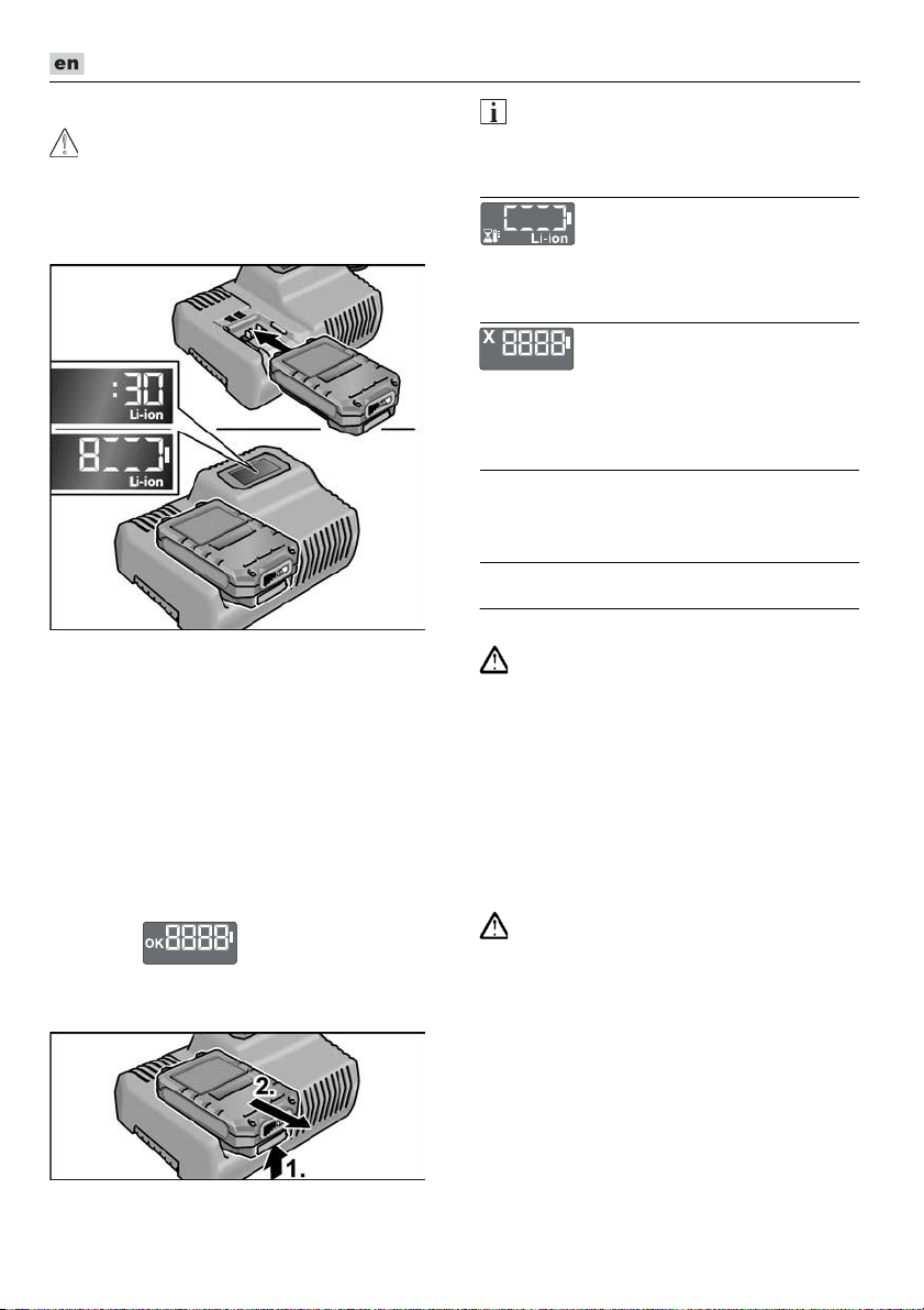
Akku vollständig bis zum Einrasten in
das Ladegerät einsetzen.
– Im Display wird abwechselnd die
Restdauer des Ladevorgangs (bis zur
vollständigen Ladung des Akkus) und
eine grafische Darstellung des
Ladezustandes angezeigt.
– Die Hintergrundbeleuchtung des
Displays leuchtet orange, wenn der
Akku weniger als 80% geladen ist.
– Ab 80% Akkuladung leuchtet das
Display grün und es wird OK
angezeigt.
Der Akku ist vollständig geladen, wenn
die Anzeige erscheint.
Die grüne Hintergrundbeleuchtung
verlischt nach kurzer Zeit.
Akku aus dem Ladegerät entnehmen.
Netzstecker ziehen.
HINWEIS
Wenn nach dem Einsetzen des Akkus in
das Ladegerät das Display blinkt, liegt ein
Fehler am Akku oder am Ladegerät vor.
Display blinkt langsam.
Hintergundbeleuchtung orange.
Der Akku ist zu heiß bzw. zu kalt. Wenn der
Akku die Ladetemperatur (0°C...55°C)
erreicht hat, beginnt der Ladevorgang.
Display blinkt schnell.
Hintergundbeleuchtung rot.
Akku aus dem Ladegerät entnehmen und
wieder einsetzen. Bei gleicher Anzeige ist
der Akku defekt. Akku austauschen oder in
einer Fachwerkstatt überprüfen lassen.
Wenn mit einem anderem Akku ebenfalls
diese Fehlermeldung angezeigt wird, liegt
ein Defekt am Ladegerät vor. Ladegerät von
einer Fachwerkstatt überprüfen lassen.
Wartung und Pflege
Reinigung
WARNUNG!
Bei der Bearbeitung von Metallen kann sich
bei extremem Einsatz leitfähiger Staub im
Gehäuseinnenraum ablagern.
Elektrowerkzeug und Lüftungsschlitze
regelmäßig reinigen. Häufigkeit ist vom
bearbeiteten Material und von der Dauer
des Gebrauchs abhängig.
Gehäuseinnenraum mit Motor regel-
mäßig mit trockener Druckluft ausblasen.
Elektrowerkzeug dabei laufen lassen.
14
Page 15

DD 2G 18.0-EC / PD 2G 18.0-EC / IW 1/2" 18.0-EC / ID 1/4" 18.0-EC
Ladegerät
WARNUNG!
Vor allen Arbeiten Netzstecker ziehen.
Kein Wasser oder flüssige Reinigungsmittel
verwenden.
Schmutz und Staub mit einem Pinsel
oder trockenem Lappen vom Gehäuse
entfernen.
Reparaturen
Reparaturen ausschließlich durch eine
vom Hersteller autorisierte Kundendienstwerkstatt ausführen lassen.
Ersatzteile und Zubehör
Weiteres Zubehör, insbesondere Einsatzwerkzeuge, den Katalogen des Herstellers
entnehmen.
Explosionszeichnungen und Ersatzteillisten
finden Sie auf unserer Homepage:
www.flex-tools.com
Transport
Die Lithiumäquivalentmenge der im Lieferumfang enthaltenen Akkus liegt unter den
einschlägigen Grenzwerten. Daher unterliegt
der Akku als Einzelteil sowie das Elektrowerkzeug mit seinem Lieferumfang nicht nationalen
oder internationalen Gefahrgutvorschriften.
Beim Transport mehrerer Geräte mit Lithiumionen-Akkus können diese Vorschriften relevant werden und besondere Sicherheitsmaßnahmen (z. B. für die Verpackung) erfordern.
Informieren Sie sich in diesem Fall über die für
das Einsatzland geltenden Vorschriften.
-Konformität
Wir erklären in alleiniger Verantwortung, dass
das unter „Technische Daten“ beschriebene
Produkt mit folgenden Normen oder
normativen Dokumenten übereinstimmt:
EN 62841 gemäß den Bestimmungen
der Richtlinien 2014/30/EU, 2006/42/EG,
2011/65/EU.
Verantwortlich für technische Unterlagen:
FLEX-Elektrowerkzeuge GmbH, R & D
Bahnhofstrasse 15, D-71711 Steinheim/Murr
18.12.2017
FLEX-Elektrowerkzeuge GmbH
Bahnhofstrasse 15, D-71711 Steinheim/Murr
Entsorgungshinweise
WARNUNG!
Ausgediente Elektrowerkzeuge vor der
Entsorgung unbrauchbar machen:
–
netzbetriebene Elektrowerkzeuge durch
Entfernen des Anschlusssteckers,
–
akkubetriebene Elektrowerkzeuge durch
Entfernen des Akkus.
Nur für EU-Länder.
Werfen Sie Elektrowerkzeuge nicht in
den Hausmüll! Gemäß Europäischer
Richtlinie 2012/19/EU über Elektro- und
Elektronik-Altgeräte und Umsetzung in
nationales Recht müssen verbrauchte
Elektrowerkzeuge getrennt gesammelt und
einer umwelt-gerechten Wiederverwertung
zugeführt werden.
Rohstoffrückgewinnung statt Müllentsorgung.
Gerät, Zubehör und Verpackung sollten einer
umweltgerechten Wiederverwertung zugeführt werden. Zum sortenreinen Recycling
sind Kunststoffteile gekennzeichnet.
WARNUNG!
Akkus/Batterien nicht in den Hausmüll,
ins Feuer oder ins Wasser werfen.
Ausgediente Akkus nicht öffnen.
Akkus/Batterien sollen gesammelt, recycelt
oder auf umweltfreundliche Weise entsorgt
werden.
15
Page 16

DD 2G 18.0-EC / PD 2G 18.0-EC / IW 1/2" 18.0-EC / ID 1/4" 18.0-EC
Nur für EU-Länder.
Gemäß Europäischer Richtlinie 2006/66/EG
müssen defekte oder verbrauchte Akkus/
Batterien getrennt gesammelt und einer
umweltgerechten Wiederverwertung
zugeführt werden.
HINWEIS
Über Entsorgungsmöglichkeiten beim
Fachhändler informieren.
Haftungsausschluss
Der Hersteller und sein Vertreter haften nicht
für Schäden und entgangenen Gewinn durch
Unterbrechung des Geschäftsbetriebes, die
durch das Produkt oder die nicht mögliche
Verwendung des Produktes verursacht wurden. Der Hersteller und sein Vertreter haften
nicht für Schäden, die durch unsachgemäße
Verwendung oder in Verbindung mit Produkten anderer Hersteller verursacht wurden.
16
Page 17
DD 2G 18.0-EC / PD 2G 18.0-EC / IW 1/2" 18.0-EC / ID 1/4" 18.0-EC
Contents
Symbols used in this manual . . . . . . . . 17
Symbols on the power tool . . . . . . . . . . 17
Important safety information . . . . . . . . . 17
Noise and vibration . . . . . . . . . . . . . . . . 19
Technical data . . . . . . . . . . . . . . . . . . . . 20
Overview . . . . . . . . . . . . . . . . . . . . . . . . 21
Instructions for use . . . . . . . . . . . . . . . . 22
Maintenance and care . . . . . . . . . . . . . . 28
Transport . . . . . . . . . . . . . . . . . . . . . . . . 29
conformity . . . . . . . . . . . . . . . . . . . . 29
Disposal information . . . . . . . . . . . . . . . 29
Exemption from liability . . . . . . . . . . . . . 29
Symbols used in this manual
WARNING!
Denotes impending danger. Nonobservance of this warning may result in
death or extremely severe injuries.
CAUTION!
Denotes a potentially dangerous situation.
Non-observance of this warning may result
in injury or damage to property.
NOTE
Denotes application tips and important
information.
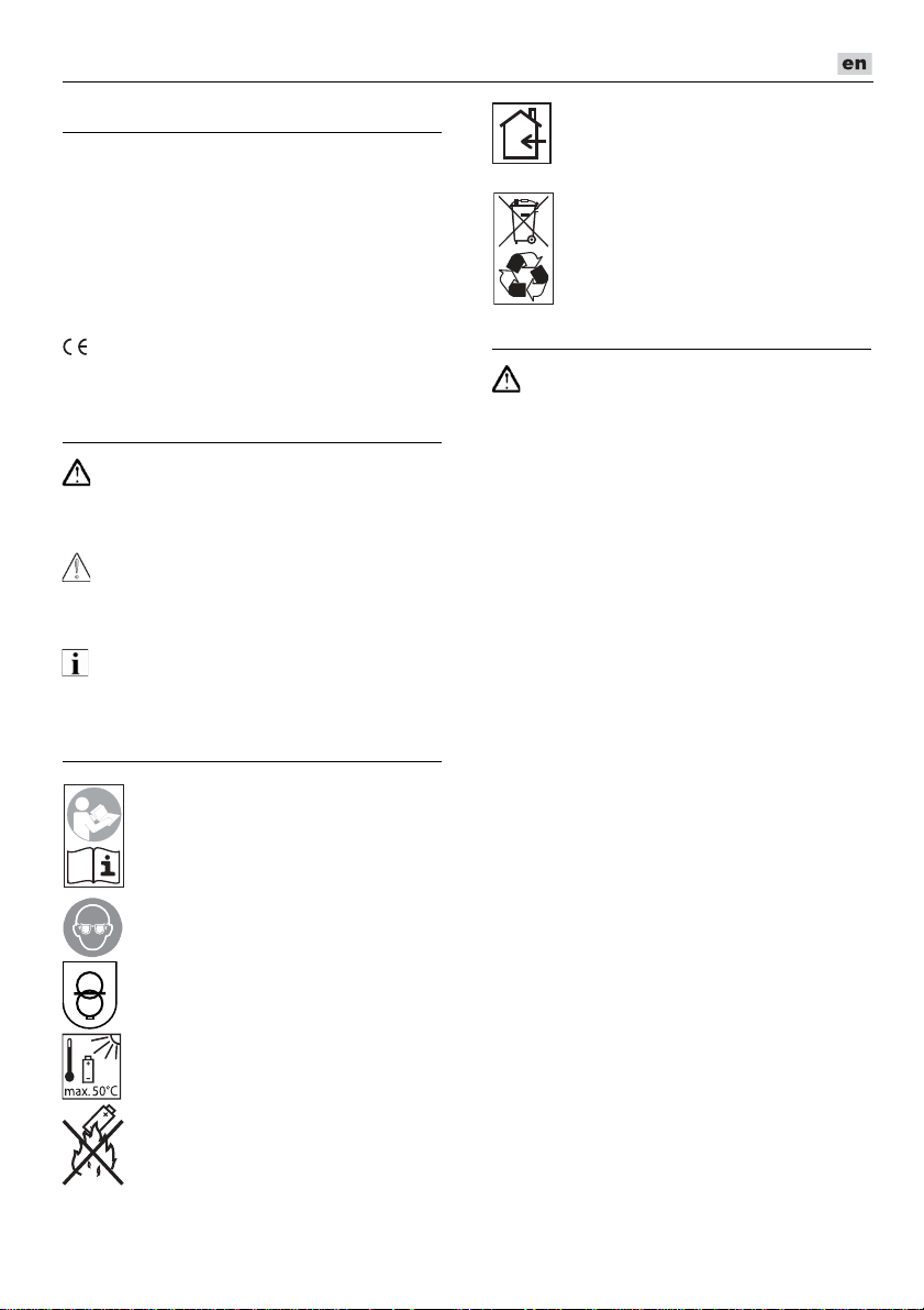
Symbols on the power tool
Before switching on the power tool
for the first time, read the
operating manual.
Wear protective goggles.
Short-circuit-proof safety
transformer.
Protect the battery against heat,
including prolonged sunshine, and
fire. Explosion hazard!.
Do not throw the battery into a fire.
Explosion hazard!
The tool is only suitable for use
indoors. Do not expose the tool to
rain. Store power tools and
batteries in dry rooms.
Disposal information
(see page 29).
Important safety information
WARNING!
Read all safety warnings, instructions, illustrations and specifications provided with
this power tool. Failure to follow all instructions listed below may result in electric
shock, fire and/or serious injury. Save all
warnings and instructions for future
reference.
Before using the power tool, please read the
following and act accordingly:
–
these operating instructions,
–
the “General safety instructions” on the
handling of power tools in the enclosed
booklet (leaflet no.: 315.915),
–
the currently valid site rules and the
regulations for the prevention of
accidents.
This power tool is state of the art and has
been constructed in accordance with the
acknowledged safety regulations.
Nevertheless, when in use, the power tool
may be a danger to life and limb of the user
or a third party, or the power tool or other
property may be damaged.
The power tool may be operated only if it is
–
for its intended use,
–
in perfect working order.
Faults which compromise safety must be
repaired immediately.
Intended use
The DD 2G 18.0-EC cordless drill driver is
intended
– for commercial use in industry and trade,
– for inserting and releasing screws,
– for drilling in wood, metal, ceramic and
plastic.
17
Page 18

DD 2G 18.0-EC / PD 2G 18.0-EC / IW 1/2" 18.0-EC / ID 1/4" 18.0-EC
The PD2G18.0-EC cordless percussion
drill is intended
– for commercial use in industry and trade,
– for inserting and releasing screws,
– for drilling in wood, metal, ceramic and
plastic,
– for impact drilling in brick, masonry and
stone.
The IW 1/2" 18.0-EC / ID 1/4" 18.0-EC
cordless impact driver is intended
– for commercial use in industry and trade,
– for tightening and releasing nuts and
screws in the specified dimensions.
Safety instructions for drills and
drivers
Hold the power tool by the insulated
gripping surfaces when performing an
operation where the cutting accessory or
the screw may contact hidden wiring or
its own power cord.
The screw contacting a “live” wire may
make exposed metal parts of the power
tool “live” and cause an electric shock.
Use auxiliary handles if these are
supplied with the power tool. The loss of
control may result in injuries.
Use suitable detectors to detect
concealed power supply cables or
consult your local supply company.
Contact with electric cables may result in
a fire and/or electric shock. A damaged
gas pipe may cause an explosion. Cutting
into a water pipe will cause damage to
property.
Switch off the power tool immediately
when the cutting accessory jams. Be
prepared for high reaction torques which
cause kickback. The cutting accessory
jams when:
– the power tool is overloaded
or
– it snags in the workpiece to be
machined.
Maintain a firm grip on the power tool.
High reaction torques can occur briefly
when screws are tightened and released.
Secure the workpiece. A workpiece is
held more securely in a clamping device or
vice than by hand.
Wait until the power tool has come to
a stop before putting it down. The cutting
accessory may snag, causing the operator
to lose control of the power tool.
Use only original batteries with the
voltage indicated on the type plate of
your power tool. The use of other
batteries, e.g. imitations, reconditioned
batteries or other makes, increases the risk
of injury and damage to property by
exploding batteries.
Additional safety instruction for
percussion drill (PD...)
Wear ear defenders when impact drilling.
The effect of noise may result in loss of
hearing.
Safety instructions for handling
batteries
Do not open the battery. Short-circuiting
hazard!
Protect the battery against heat,
including prolonged sunshine, fire, water
and moisture. Explosion hazard!
A damaged or incorrectly used battery may
result in the emission of fumes.
Ensure a supply of fresh air and consult
a doctor in the event of any physical
complications. The fumes may irritate the
respiratory tracts.
Liquid may leak out of the battery if the
battery is incorrectly used. Avoid contact
with such liquid. If contact accidentally
occurs, rinse with water. If liquid contacts
eyes, seek medical attention.
Liquid discharged from the battery may
cause irritation or burns.
Recharge batteries only with chargers
recommended by the manufacturer.
A charger that is suitable for one type of
battery may create a fire hazard when used
with another battery.
The battery may be damaged by pointed
objects such as e.g. nails or screwdrivers or
by external application of force. This may
give rise to an internal short circuit, causing
the battery to burn, smoke, explode or
overheat.
18
Page 19
DD 2G 18.0-EC / PD 2G 18.0-EC / IW 1/2" 18.0-EC / ID 1/4" 18.0-EC
Charger
Always check whether the mains voltage
matches the voltage indicated on the
type plate of the charger.
The charger plug must fit in the power
socket. Never modify the plug in any way.
Do not use any adapter plugs together with
earthed (grounded) power tools.
Unmodified plugs and matching power
sockets will reduce the risk of electric shock.
Only use the charger in dry rooms and
avoid all contact with moisture and rain.
The ingress of water into the charger
increases the risk of electric shock.
Never use the charger if cables, plugs or
the device itself are damaged as a result
of external influence. Take the charger to
the nearest authorised repair shop.
Under no circumstances open the
charger. In the event of a fault, take it to an
authorised repair shop.
Do not place any objects on the charger
and do not place the charger on soft
surfaces. Fire hazard!
Special safety instructions
Before carrying out any work on the power
tool, move the direction preselector
switch (2) to the middle position.
Operate the direction preselector
switch (2) or torque setting turning
dial (5) only when the tool is stopped.
Identify the power tool with stickers only.
Do not drill any holes into the housing.
NOTE
The vibration emission level given in this
information sheet has been measured in
accordance with a measurement method
standardised in EN 62841 and may be used
to compare one tool with another. It may be
used for a preliminary assessment of
exposure. The specified vibration emission
level represents the main applications of the
tool.
However, if the tool is used for different
applications, with different cutting
accessories or poorly maintained, the
vibration emission level may differ.
This may significantly increase the
exposure level over the total working period.
To
make an accurate estimation of the
vibration exposure level, it is also necessary to
take into account the times when the tool is
switched off or running but not actually in use.
This may significantly decrease the exposure
level over the total working period.
Identify additional safety measures to protect
the operator from the effects of vibration such
as: maintain the tool and the cutting
accessories, keep the hands warm,
organisation of work patterns.
CAUTION!
Wear ear defenders at a sound pressure
above 85 dB(A).
Noise and vibration
NOTE
The noise and vibration values have been
determined in accordance with EN 62841.
The values are set out in the “Technical
data” table.
WARNING!
The indicated measurements refer to new
power tools. Daily use causes the noise and
vibration values to change.
19
Page 20

Technical data
DD 2G 18.0-EC / PD 2G 18.0-EC / IW 1/2" 18.0-EC / ID 1/4" 18.0-EC
Tool DD 2G
18.0-EC
Type
Drill driver Impact drill
PD 2G
18.0-EC
driver
IW 1/2"
18.0-EC
Impact
driver
Battery AP 18.0/2.5
AP 18.0/5.0
Charging time (depending on
state of charge)
– AP 18.0/2.5
– AP 18.0/5.0
min
min
0–40
0–45
Torque, max.
– Soft screwdriving case
– Hard screwdriving case
Nm
Nm
56
90
56
90
–
250
Torque settings 20 24 –
Idling speed
– Stage 1
– Stage 2
– Stage 3
r.p.m.
r.p.m.
r.p.m.
0...600
0...2300
–
0...600
0...2300
–
1500
2000
2500
Schlagzahl
– Stage 1
– Stage 2
– Stage 3
r.p.m.
r.p.m.
r.p.m.
–
–
–
0...9600
0...37000
–
1300
2800
3300
Chuck mm 1.5–13 –
Max. drill diameter
– in wood
– in steel
– in masonry
mm
mm
mm
60
13
16
60
13
16
–
–
–
Weight according to “EPTA
Procedure 01/2003”
kg 1.5 1.6 1.1 1.1
(without battery)
Weight battery 2.5 Ah
5.0 Ah
kg
kg
0.4
0.7
A-weighted sound pressure level
Sound pressure level L
Sound power level L
WA
pA
dB(A) 78* 78* / 95** 91*** 91***
dB(A) 89*
89* /
106**
102*** 102***
Uncertainty K db 3.0
Overall vibration values (vector sum of three directions)
Vibration emission value ah when ....
– drilling in metal
– impact drilling in concrete
– screwing
Uncertainty K
* drilling in metal / ** impact drilling in concrete / *** impact driving
m/s
m/s
m/s
m/s
2
2
2
2
<2.5 <2.5 – –
–15.5 – –
<2.5 <2.5 18.5*** 18.5***
1.5
ID 1/4"
18.0-EC
Impact
driver
–
225
1500
2000
2500
1300
2800
3300
–
–
–
20
Page 21

DD 2G 18.0-EC / PD 2G 18.0-EC / IW 1/2" 18.0-EC / ID 1/4" 18.0-EC
Overview
Different electric power tools are described in these instructions. The illustrated electric power
tool may differ in detail from the one which you purchased.
1 Trigger switch
For switching on and off and for
accelerating up to maximum rotational
speed
2 Direction preselector switch
3 Speed selector switch
4 Turning dial for operating mode
(PD... only)
5 Turning dial for torque setting
6 Tool holder
7 Workplace lighting
8 Handle
9 Speed control panel
10 Insertion slot for battery
11 Angle attachment with release ring
12 Exchange chuck with release ring
13 Bit holder attachment with release ring
14 Auxiliary handle
15 Li-ion battery (2.5 Ah)
16 Release button for battery
17 State of charge indicator
18 Li-ion battery (5.0 Ah)
19 Belt clip
20 Fastening screw
21 Bit bracket
21
Page 22
DD 2G 18.0-EC / PD 2G 18.0-EC / IW 1/2" 18.0-EC / ID 1/4" 18.0-EC
Instructions for use
Before initial operation
Unpack the power tool and accessories
and check that no parts are missing or
damaged.
Attach the belt clip and bit holder with
the enclosed fastening screw.
NOTE
The batteries are not fully charged on
delivery. Prior to initial operation, charge
the batteries fully. See “Charger/Charging
process”.
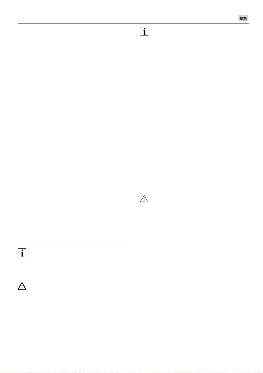
Fitting/removing the auxiliary
handle (PD/DD 2G 18.0-EC)
CAUTION!
Use auxiliary handles if these are supplied
with the power tool. The loss of control may
result in injuries.
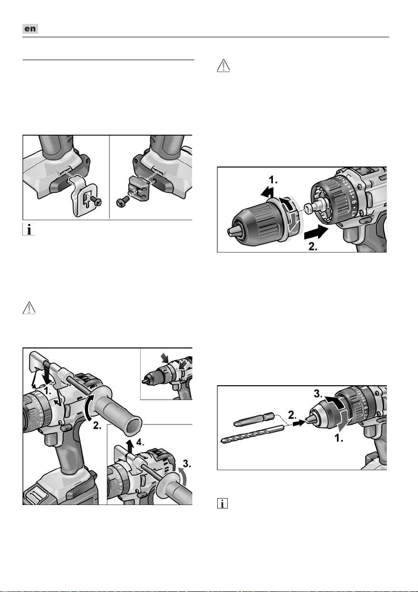
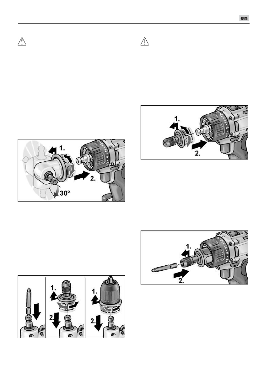
Changeable drill chuck BF 18.0-EC
CAUTION!
Before carrying out any work on the power
tool, move the direction preselector switch (2)
to the middle position.
Assemble
Pull unlocking ring forwards (1.) and
press the drill chuck all the way onto the
tool holder (2.).
Release unlocking ring. Check that the
drill chuck is locked in position.
Disassemble
Pull unlocking ring forwards and remove
the drill chuck.
Inserting the tools
Drill bits with a diameter of 1.5–13 mm,
½" screwdriver bits and ½" bit holders are
securely held in the drill chuck.
Grip the power tool firmly with one hand
and turn the chuck with the other hand.
– Turn counterclockwise to open the chuck
further.
– Turn clockwise to close the chuck.
22
Insert the tool.
Close the chuck fully.
NOTE
Carry out a test run to check that the tool is
chucked in the centre.
Page 23
DD 2G 18.0-EC / PD 2G 18.0-EC / IW 1/2" 18.0-EC / ID 1/4" 18.0-EC
Angle attachment WV 18.0-EC
CAUTION!
Before carrying out any work on the power
tool, move the direction preselector switch (2)
to the middle position.
The angle attachment facilitates working in
places which are difficult to access.
The angle attachment can be locked in
different 30° angular positions.
Assemble
Pull unlocking ring forwards (1.) and
press angle attachment all the way onto
the tool holder (2.).
Lock angle attachment in the required
angular position.
Release unlocking ring. Check that the
attachment is locked in position.
Disassemble
Pull unlocking ring forwards and remove
angle attachment.
Inserting the tools
The angle attachment has a ½" tool holder.
Screwdriver bits and bit holders are
securely held in the tool holder.
The keyless chuck (see “Changeable drill
chuck BF 18.0-EC”) or the bit holder (see
“Bit holder attachment BV 18.0-EC”) can be
mounted on the angle attachment.
Bit holder attachment BV 18.0-EC
CAUTION!
Before carrying out any work on the power
tool, move the direction preselector switch (2)
to the middle position.
Assemble
Pull unlocking ring forwards (1.) and
press bit holder attachment all the way
onto the tool holder (2.).
Release unlocking ring. Check that the bit
holder attachment is locked in position.
Disassemble
Pull unlocking ring forwards and remove
bit holder attachment.
Inserting the tools
The bit holder attachment has a ½" tool
holder. Screw-driver bits are securely held
in the tool holder.
Pull tool lock forwards (1.) and press in
the tool all the way (2.).
Release tool lock.
To remove the tool, pull tool lock
backwards.
23
Page 24
DD 2G 18.0-EC / PD 2G 18.0-EC / IW 1/2" 18.0-EC / ID 1/4" 18.0-EC
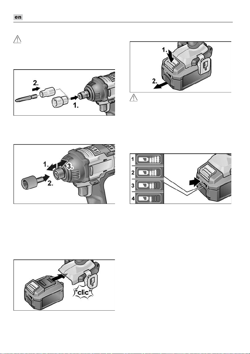
Tool change
CAUTION!
Before carrying out any work on the power
tool, move the direction preselector switch (2)
to the middle position.
IW 1/2“ 18.0-EC:
Push adapter on square drive of impact
driver (1.).
Insert tool in adapter (2.).
ID 1/4“ 18.0-EC:
To remove, press the release button (1.)
and pull out the battery (2.).
CAUTION!
Protect the battery contacts when the
battery is not being used. Loose metal parts
may short-circuit the contacts –
Explosion and fire hazard!
Battery state of charge
Press the button to check the state of
charge at the state of charge indicator
LEDs.
Pull tool lock forwards (1.) and press in
the tool all the way (2.).
Release tool lock.
To remove the tool, pull tool lock
backwards (3.).
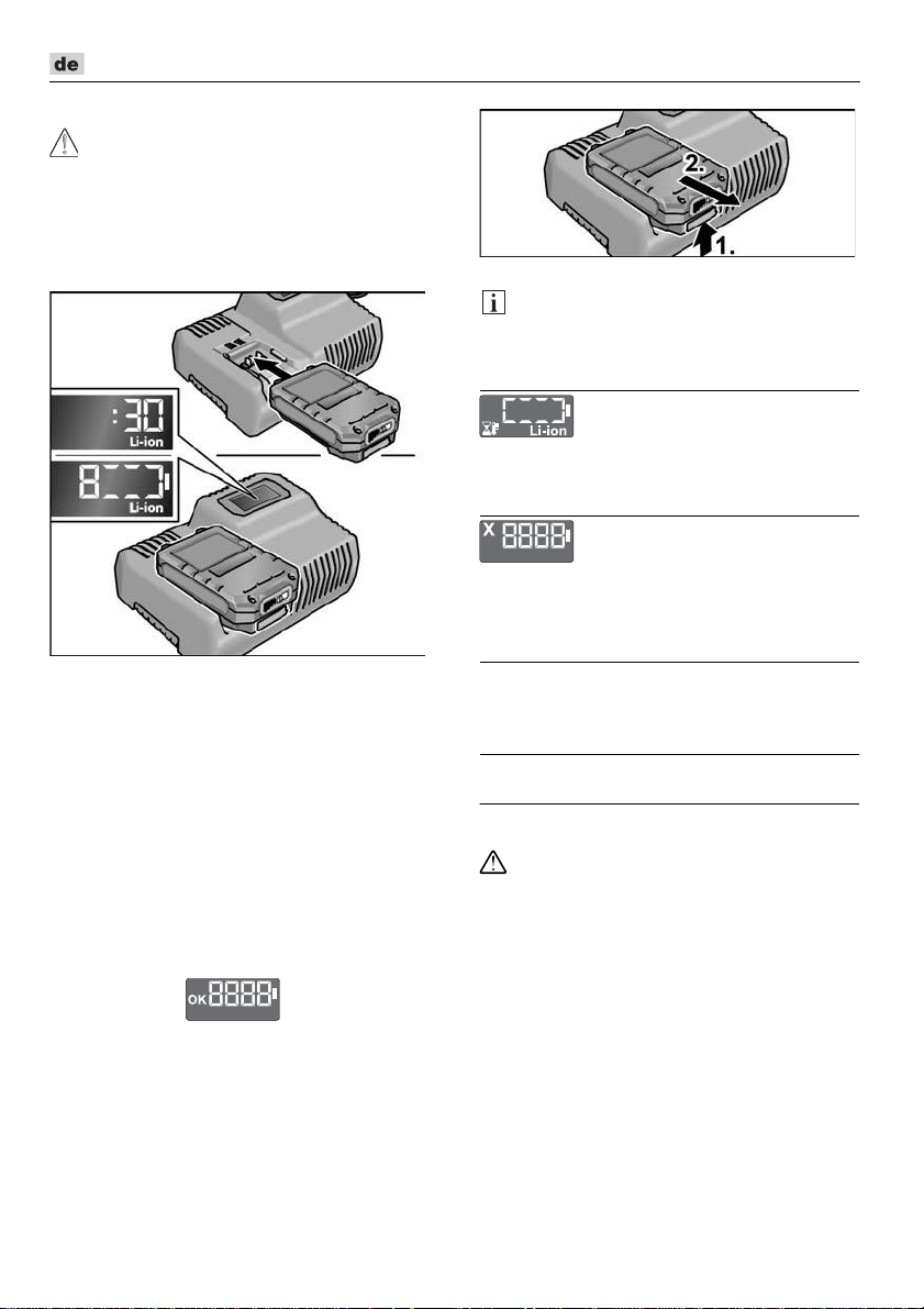
Inserting/replacing the battery
Press the charged battery into the power
tool until it clicks into place.
24
The indicator goes out after 5 seconds.
If one of the LEDs flashes, the battery must
be recharged. If none of the LEDs light up
after the button is pressed, the battery is
faulty and must be replaced.
Page 25

DD 2G 18.0-EC / PD 2G 18.0-EC / IW 1/2" 18.0-EC / ID 1/4" 18.0-EC
Direction preselection
CAUTION!
Change the direction of rotation only when
the power tool is stopped.
Move the direction preselector switch to
the required position:
– Left: counterclockwise (remove screws,
release screws)
– Right: clockwise (drill, insert screws,
tighten down screws)
– Middle: switch-on interlock (tool change,
when working on the power tool)
Operating mode
(PD 2G 18.0-EC only)
CAUTION!
Change the operating mode only when the
power tool is stopped.
Move the operating mode turning dial to
the required position.
Torque preselection
CAUTION!
Change the torque only when the power tool
is stopped.
Move the torque setting turning dial to the
required position.
DD 2G 18.0-EC:
1–23: Screwing
: Drilling
NOTE
The safety clutch is deactivated in the
Drilling setting .
PD 2G 18.0-EC:
Speed preselection
CAUTION!
Change the speed only when the power tool
is stopped.
: Drilling
: Screwing
: Impact drilling
Move the selector switch to the required
stage:
1: Low speed, high torque
2: High speed, low torque
25
Page 26
DD 2G 18.0-EC / PD 2G 18.0-EC / IW 1/2" 18.0-EC / ID 1/4" 18.0-EC
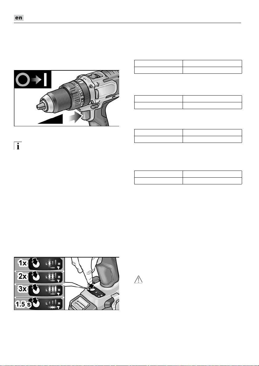
Switching on the power tool
To switch the power tool on:
Press the trigger switch.
The power tool trigger switch allows the
operator to increase the speed in
increments up to the maximum speed.
To switch the power tool off:
Release the trigger switch.
NOTE
–
The power tool is equipped with a brake
which stops the cutting accessory as
soon as the trigger switch is released.
–
When using the power tool continuously,
the operator should work primarily with
the trigger switch fully depressed.
Workplace lamp on/off switch
1. Turn direction of rotation preselector
switch (2) to “Forwards” or “Reverse”.
2. Press electric tool on/off switch (1)
– Workplace lamp lights up
3. Release electric tool on/off switch (1)
– Workplace lamp goes out
automatically after approx. 10 sec.
Speed and torque preselector switch
IW 1/2” 18.0-EC / ID 1/4“ 18.0-EC
Change speed/torque
1. Activate on/off switch (1)
2. Press mode switch briefly (approx. 0.5 sec.).
– An LED lights up – torque:
IW 1/2“ 18.0-EC: 150 Nm / 1500 rpm
ID 1/4“ 18.0-EC: 60 Nm / 1500 rpm
3. Press mode switch briefly
– Two LEDs light up – torque:
IW 1/2“ 18.0-EC: 180 Nm / 2000 rpm
ID 1/4“ 18.0-EC: 105 Nm / 2000 rpm
4. Press mode switch briefly
– Three LEDs light up – torque:
IW 1/2“ 18.0-EC: 250 Nm / 2500 rpm
ID 1/4“ 18.0-EC: 225 Nm / 2500 rpm
5. Press mode switch briefly
– An LED lights up – torque switches
back to:
IW 1/2“ 18.0-EC: 150 Nm
ID 1/4“ 18.0-EC: 60 Nm
Torque can be increased again as described.
During reverse operation of the electric tool
– which only has one speed – the LEDs in
the base go out automatically.
Change single impact mode to impact
driver mode
Press mode switch for approx.
1.5 seconds.
– LED mode indicator lights up – single
impact mode active
– LED mode indicator not lit – impact
driver mode active.
Working with the power tool
CAUTION!
Before carrying out any work on the power
tool, move the direction preselector switch (2)
to the middle position.
26
Page 27
DD 2G 18.0-EC / PD 2G 18.0-EC / IW 1/2" 18.0-EC / ID 1/4" 18.0-EC
NOTE
To facilitate handling of the appliance when
inserting screws, the screwdriver bit can be
inserted directly into the tool holder of the
appliance.
1. Assemble the tool head (drill chuck, angle
attachment, bit holder attachment).
2. Insert the battery.
3. Insert the tool (drill bits, srewdriver bits,
bit holders).
4. Set operating mode according to the
work item (PD ... only).
5. Set torque preselection to the required
setting.
6. Set speed to the required setting.
7. Set the required direction of rotation.
8. Hold the power tool with one hand on the
handle and assume the working position.
If the power tool is running, never actuate
the direction preselector switch or torque
setting turning dial.
9. Switch on the power tool.
At the end of work:
10. Release the trigger switch.
11. Move the direction preselector
switch (2) to the middle position.
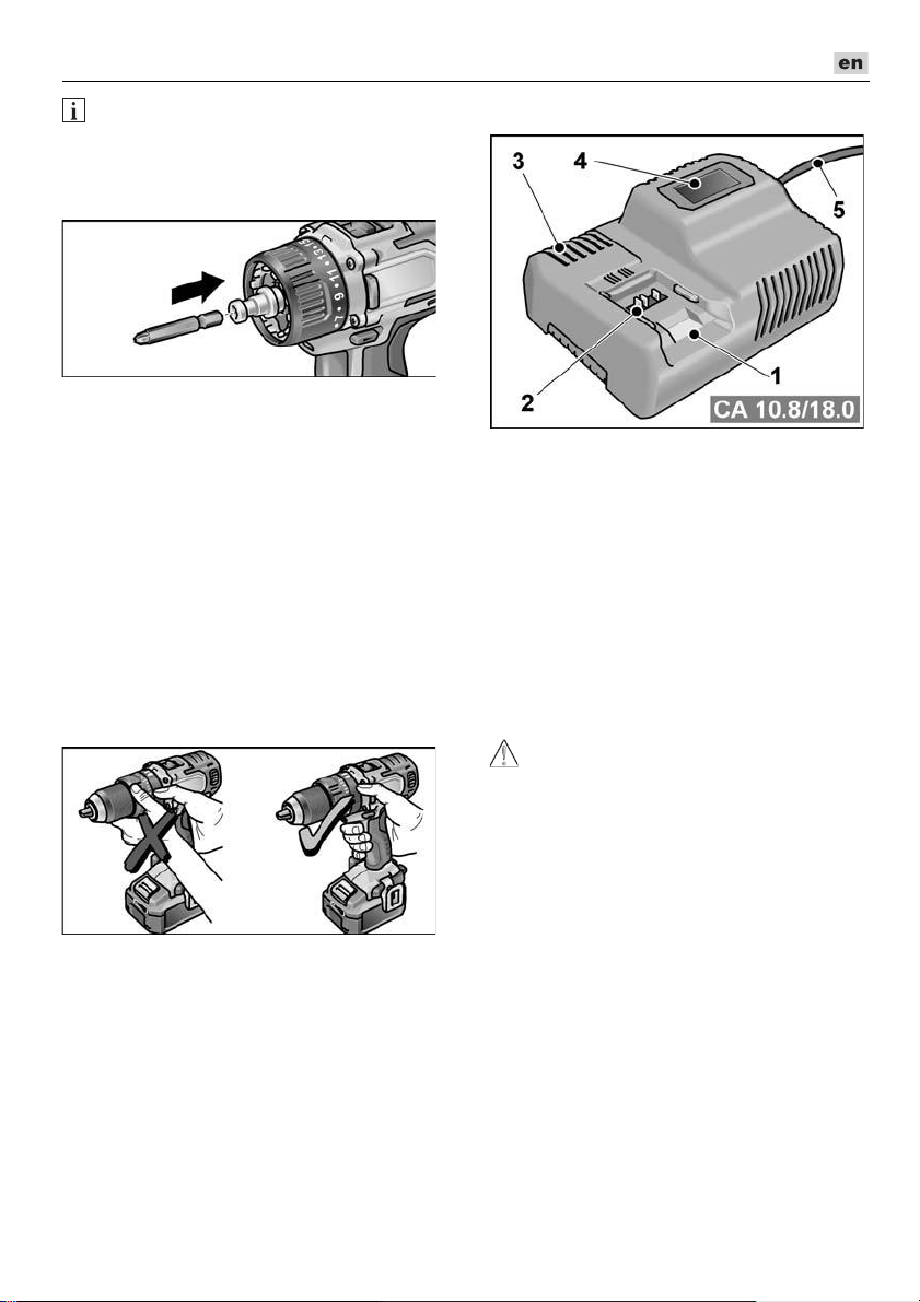
Charger
1 Insertion slot for battery
2 Contacts
3 Ventilation slots
4 Operating state display
5 Power cord with mains plug
The CA 10.8/18.0 charger is designed to
charge FLEX batteries of the following types
– AP 10.8 (2.5 Ah),
– AP 18.0 (2.5 Ah),
– AP 10.8 (5.0 Ah),
– AP 18.0 (5.0 Ah).
Tips for a long battery service life
CAUTION!
–
Never charge batteries at temperatures
below 0 °C or above 55 °C.
–
Do not charge batteries in environments
with high air humidity or ambient
temperature
–
Do not cover batteries and the charger
during the charging process.
–
Pull out the charger mains plug at the end
of the charging process.
Battery and charger heat up during the
charging process. This is perfectly normal!
Lithium-ion batteries do not exhibit the
established “memory effect”. Nevertheless,
a battery should be completely discharged
before charging and the charging process
should always be fully completed.
If batteries are not used for an extended
period of time, store them partially charged
in a cool place.
27
Page 28
DD 2G 18.0-EC / PD 2G 18.0-EC / IW 1/2" 18.0-EC / ID 1/4" 18.0-EC
Charging process
CAUTION!
Insert only original batteries in the supplied
charger.
Insert the charger mains plug. The display
backlighting lights up green for 2 seconds
and then goes out again. OK is displayed.
Insert the battery fully into the charger
until it clicks into place.
– The time remaining in the charging
process (until the battery is fully
charged) and a graphic representation
of the state of charge are shown
alternately in the display.
– The display backlighting lights up
orange when the battery is charged
less than 80%.
– When the battery charge reaches 80%
the display lights up green and OK is
indicated.
The battery is fully charged when the
display appears.
The green backlighting goes out after
a short time.
Remove the battery from the charger.
NOTE
If the display flashes after the battery is
inserted in the charger, there is a fault in the
battery or in the charger.
Display flashes slowly.
Backlighting orange.
The battery is too hot or too cold. The charging
process starts when the battery reaches the
charging temperature (0°C...55°C).
Display flashes rapidly.
Backlighting red.
Remove the battery from the charger and
insert again. If the same display persists, the
battery is faulty. Replace the battery or have
it checked at an authorised repair shop.
If this error message is displayed again with
a different battery, this indicates that there
is a fault in the charger. Have the charger
checked at an authorised repair shop.
Maintenance and care
Cleaning
WARNING!
If metals are worked over a prolonged
period, electroconductive dust may become
deposited inside the housing.
Clean the power tool and ventilation slots at
regular intervals. Frequency of cleaning is
dependent on the material machined and
the duration of use.
Regularly blow out the housing interior
and motor with dry compressed air. Keep
the power tool running while doing this.
Charger
WARNING!
Before performing any work, pull out
the mains plug. Do not use water or liquid
detergents.
Remove dirt and dust from the housing
with a brush or a dry cloth.
Repairs
Repairs may be carried out by an authorised
customer service centre only.
Pull out the mains plug.
28
Page 29

DD 2G 18.0-EC / PD 2G 18.0-EC / IW 1/2" 18.0-EC / ID 1/4" 18.0-EC
Spare parts and accessories
For other accessories, in particular cutting
accessories, please refer to the
manufacturer’s catalogues.
Exploded drawings and spare-part lists can
be found on our homepage:
www.flex-tools.com
Transport
The lithium equivalent content of the batteries
contained in the scope of delivery is below the
relevant limit values. Therefore the battery as
a separate component and the power tool with
its scope of delivery are not subject to national
or international dangerous goods regulations.
If several devices containing lithium-ion
batteries are transported, these regulations
may become relevant and require special
safety measures (e.g. for the packaging).
In this case acquaint yourself with the
regulations that apply to the country of use.
conformity
We declare on our sole responsibility that the
product described in “Technical data”
conforms to the following standards or
normative documents:
EN 62841 according to the provisions of
Directives 2014/30/EU, 2006/42/EC,
2011/65/EU.
Responsible for technical documents:
FLEX-Elektrowerkzeuge GmbH, R & D
Bahnhofstrasse 15, D-71711 Steinheim/Murr
18.12.2017; FLEX-Elektrowerkzeuge GmbH
Bahnhofstrasse 15, D-71711 Steinheim/Murr
Disposal information
WARNING!
Render redundant power tools unusable:
–
mains operated power tool by removing
the power cord,
–
battery operated power tool by removing
the battery.
EU countries only.
Do not dispose of electric power tools in
the household waste! In accordance with
the European Directive 2012/19/EU on
Waste Electrical and Electronic Equipment
and its incorporation into national law, used
power tools must be collected separately
and recycled in an environmentally friendly
manner.
Raw material recovery instead of
waste disposal.
Device, accessories and packaging should
be recycled in an environmentally friendly
manner. Plastic parts are identified for
recycling according to material type.
WARNING!
Do not throw batteries into the household
waste, fire or water. Do not open disused
batteries.
Accumulators/batteries should be collected,
recycled or disposed of in an environmentally
friendly manner.
EU countries only.
In accordance with the European Directive
2006/66/EC on Waste Electrical and
Electronic Equipment and its incorporation
into national law, defective or used batteries
must be collected separately and recycled
in an environmentally friendly manner.
NOTE
Please ask your dealer about disposal
options.
Exemption from liability
The manufacturer and his representative
are not liable for any damage and lost profit
due to interruption in business caused
by the product or by an unusable product.
The manufacturer and his representative
are not liable for any damage which was
caused by improper use of the product or by
use of the product with products from other
manufacturers.
29
Page 30
DD 2G 18.0-EC / PD 2G 18.0-EC / IW 1/2" 18.0-EC / ID 1/4" 18.0-EC
Table des matières
Symboles utilisés . . . . . . . . . . . . . . . . . . 30
Symboles apposés sur l’appareil . . . . . . 30
Pour votre sécurité . . . . . . . . . . . . . . . . 30
Bruit et vibrations . . . . . . . . . . . . . . . . . . 32
Données techniques . . . . . . . . . . . . . . . 33
Vue d’ensemble . . . . . . . . . . . . . . . . . . . 34
Instructions d’utilisation . . . . . . . . . . . . . 35
Maintenance et nettoyage . . . . . . . . . . . 41
Transport . . . . . . . . . . . . . . . . . . . . . . . . 42
Conformité . . . . . . . . . . . . . . . . . . . . 42
Consignes pour la mise au rebut . . . . . . 42
Exclusion de responsabilité . . . . . . . . . . 43
Symboles utilisés
AVERTISSEMENT !
Ce symbole prévient d’un danger imminent ;
le non-respect des consignes qui le suivent
s’accompagne d’un danger de mort ou de
blessures très graves.
PRUDENCE !
Ce symbole désigne une situation potentiellement dangereuse. Si vous ne respectez
pas cette consigne, vous risquez de vous
blesser ou de causer des dégâts matériels.
REMARQUE
Ce symbole vous donne des conseils
d’utilisation et des informations importantes.
Symboles apposés sur l’appareil
Avant la mise en service, veuillez
lire la notice d’instructions.
Portez des lunettes de protection !
Transformateur de sécurité contre
les courts-circuits
Protégez l'accumulateur de la
chaleur, par ex. les rayons directs
et continus du soleil ou le feu.
Il y a un risque d'explosion.
Ne jetez pas l'accumulateur au
feu. Il y a un risque d'explosion.
L'appareil n'est pas conçu pour
une utilisation en intérieur.
N'exposez pas l'appareil à la pluie.
Stockez l'outil électrique et les
accus dans un endroit sec.
Consignes pour la mise au rebut
(voir page 42)!
Pour votre sécurité
AVERTISSEMENT !
Lire tous les avertissements de sécurité, les
instructions, les illustrations et les spéci-
fications fournis avec cet outil électrique.
Ne pas suivre les instructions énumérées
ci-dessous peut provoquer un choc électrique, un incendie et/ou une blessure
sérieuse. Conserver tous les avertissements et toutes les instructions pour pouvoir
s'y reporter ultérieurement.
Avant d’utiliser cet appareil électrique,
veuillez lire et respecter :
–
la présente notice d’utilisation,
–
les « Consignes générales de sécurité »
régissant l’emploi des appareils
électriques et réunies dans le fascicule
ci joint (référence : 315.915),
–
les règles et prescriptions préventives
des accidents applicables sur le lieu de
mise en œuvre.
Cet appareil électrique a été construit en
l’état de la technique et des règles
techniques de sécurité reconnues.
Toutefois, de son emploi peut émaner un
danger de mort et un risque de blessures
graves pour l’utilisateur ou les tiers, ou un
risque d’endommager la machine ellemême ou d’autres objets de valeur.
Il convient d'utiliser cet appareil électrique
uniquement
–
à des fins conformes à l’usage prévu,
–
dans un état technique et de sécurité
parfait.
Supprimez immédiatement tout
dysfonctionnement susceptible de
compromettre la sécurité.
30
Page 31

DD 2G 18.0-EC / PD 2G 18.0-EC / IW 1/2" 18.0-EC / ID 1/4" 18.0-EC
Conformité d’utilisation
La perceuse-visseuse sans fil
DD 2G 18.0-EC est destinée
– aux utilisations professionnelles dans
l’industrie et l’artisanat,
– au vissage et dévissage des vis,
– au perçage du bois, du métal, de la
céramique et du plastique.
La perceuse à percussion sans fil
PD 2G 18.0-EC est destinée
– aux utilisations professionnelles dans
l’industrie et l’artisanat,
– au vissage et dévissage des vis,
– au perçage du bois, du métal, de la
céramique et du plastique,
– au perçage à percussion dans la brique,
la maçonnerie et la pierre.
La clé à chocs sans fil IW 1/2" 18.0-EC /
ID 1/4" 18.0-EC est destinée
– aux utilisations professionnelles dans
l’industrie et l’artisanat,
– au serrage et desserrage des écrous et
vis de dimensions spécifiées.
Consignes de sécurité pour
perceuses et visseuses
Ne tenez l’appareil que par ses poignées
isolantes lors de travaux au cours
desquels l’outil installé ou la vis risque de
toucher des câbles électriques invisibles
ou le cordon d’alimentation de l’appareil.
Le contact de la vis avec une ligne électrique peut mettre les pièces métalliques
sous tension et provoquer une
électrocution.
Utilisez les poignées d'appoint fournies
avec l'outil électrique. Une perte de
contrôle peut provoquer des blessures.
Utilisez des détecteurs appropriés pour
localiser les lignes / conduites d’alimentation occultées, ou faites appel aux
compagnies distributrices compétentes
dans votre localité. Une entrée en contact
avec des câbles électriques peut provoquer un incendie et une électrocution.
L’endommagement d’une conduite de gaz
peut provoquer une explosion. La pénétration de l’outil dans une conduite d’eau
engendre des dégâts matériels.
Éteignez immédiatement l'outil électrique
si l'outil installé est bloqué. Préparezvous au fait que les couples de réaction
élevés provoquent un recul.
L'outil installé se bloque si :
– l'outil électrique est surchargé
ou
– il se coince dans la pièce à usiner.
Tenez fermement l'outil électrique.
Lors du serrage et desserrage de vis,
des couples de réaction élevés peuvent
survenir à court terme.
Sécurisez la pièce. Une pièce retenue au
moyen de dispositifs de serrage ou d’un
étau l’est plus sûrement qu’avec la main.
Veuillez attendre l'arrêt complet de l'outil
électrique avant de le déposer. L'outil
installé risque de se coincer et d'entraîner
une perte de contrôle sur l'outil électrique.
Utilisez uniquement des accumulateurs
d'origine correspondant à la tension
indiquée sur la plaque signalétique de
votre outil électrique. En cas d'utilisation
d'autres accumulateurs, par ex. contrefaçons, accumulateurs recyclés ou
d'autres marques, il y a un risque de
blessures ou de dommages provoqués par
explosion de l'accumulateur.
Consignes de sécurité supplémentaires pour la perceuse
à percussion (PD...)
Portez un casque anti-bruit lors du
perçage à percussion. L’impact du bruit
peut provoquer une perte d’acuité auditive.
Consignes de sécurité pour le
maniement des accus
N'ouvrez pas l'accu. Il y a un risque de
court-circuit.
Protégez l'accu de la chaleur (par ex. des
rayonnements permanents du soleil), du
feu, de l'eau et de l'humidité. Risque
d'explosion.
En cas de dommage et d'utilisation non
conforme de l'accu, des vapeurs peuvent
s'échapper. Assurez un apport d'air frais et
rendez-vous chez un médecin en cas de
troubles. Les vapeurs peuvent irriter les
voies respiratoires.
En cas d’utilisation abusive, du liquide peut
sortir de l’accumulateur. Évitez tout contact
avec ce liquide. En cas de contact par
mégarde, rincez soigneusement avec de
31
Page 32

DD 2G 18.0-EC / PD 2G 18.0-EC / IW 1/2" 18.0-EC / ID 1/4" 18.0-EC
l’eau. Au cas où le liquide rentrerait dans
les yeux, consultez en plus un médecin.
Le liquide qui sort de l’accumulateur peut
entraîner des irritations de la peau ou
causer des brûlures.
Ne chargez les accumulateurs qu'avec des
chargeurs recommandés par le fabricant.
Un chargeur approprié à un type spécifique
d’accumulateur peut engendrer un risque
d’incendie lorsqu’il est utilisé avec d’autres
accumulateurs.
L'accu risque d'être endommagé par des
objets pointus comme par exemple les
clous, tournevis ou par la pénétration d'une
force externe. Un court-circuit interne
risque de se produire et l'accu risque de
brûler, fumer, exploser ou surchauffer.
Chargeur
Vérifiez toujours si la tension de réseau
correspond à la tension indiquée sur la
plaque signalétique du chargeur.
La fiche de secteur du chargeur doit être
appropriée à la prise de courant. Ne modifiez en aucun cas la fiche. N’utilisez
pas de fiches d’adaptateur avec des
appareils avec mise à la terre. Les fiches
non modifiées et les prises de courant
appropriées réduisent le risque de choc
électrique.
Utilisez le chargeur uniquement dans
des locaux secs et évitez tout contact
avec l'humidité et la pluie.
La pénétration d’eau dans le chargeur
augmente le risque d’un choc électrique.
N'utilisez jamais le chargeur si le câble,
la prise ou l'appareil lui-même sont
endommagés par des influences
extérieures. Apportez le chargeur
à l'atelier le plus proche.
N'ouvrez jamais le chargeur. En cas de
dysfonctionnement, apportez-le dans un
atelier spécialisé.
Ne posez aucun objet sur le chargeur et
ne le placez pas sur une surface molle.
Il y a un risque d'incendie.
Consignes de sécurité particulières
Avant tout travail sur l'outil électrique,
placez le sélecteur du sens de rotation (2)
en position centrale.
Actionnez le sélecteur du sens de
rotation (2) ou le réglage du couple (5)
uniquement lorsque l'outil est à l'arrêt.
Pour marquer l’outil électrique, n’utilisez
que des étiquettes autocollantes.
Ne percez jamais de trous dans le corps
de l’appareil.
Bruit et vibrations
REMARQUE
Les niveaux de bruits et vibrations ont été
déterminés conformément à EN 62841.
Vous trouverez les valeurs dans le tableau
« Données techniques
AVERTISSEMENT !
Les valeurs de mesure indiquées
s’appliquent aux appareils neufs. Pendant
la mise en œuvre quotidienne, les valeurs
de bruit et de vibrations varient.
REMARQUE
Le niveau de vibrations indiqué dans ces
instructions a été mesuré selon un procédé
standardisé dans la norme EN 62841, et peut
servir à comparer les outils électroportatifs
entre eux. Ce procédé convient également
pour estimer provisoirement la contrainte en
vibrations. Le niveau de vibrations indiqué se
réfère aux principales applications de l’outil
électrique. Si toutefois ce dernier est utilisé
à d’autres fins, avec des outils montés
différents ou s’il ne subit qu’une maintenance
insuffisante, le niveau de vibrations pourra
dévier de ce qui est indiqué. Cela peut
accroître nettement la contrainte en vibrations
sur l’ensemble de la période de travail.
Pour une estimation précise de la contrainte
en vibrations, il faudrait également tenir
compte des temps au cours desquels
l’appareil est éteint ou bien de ceux au cours
desquels il tourne sans que l'utilisateur ne s'en
serve. Cela peut réduire nettement la
contrainte en vibrations sur l’ensemble de la
période de travail. Pour protéger l’utilisateur
contre les effets des vibrations, définissez des
mesures de sécurité supplémentaires, dont
par exemple: maintenance de l’outil électrique
et des outils installés, maintien des mains au
chaud, organisation des séquences de travail.
PRUDENCE !
Lorsque la pression acoustique dépasse
85 dB(A), veuillez porter un casque antibruit.
»
.
32
Page 33

DD 2G 18.0-EC / PD 2G 18.0-EC / IW 1/2" 18.0-EC / ID 1/4" 18.0-EC
Données techniques
Appareil DD 2G
18.0-EC
Type Perceuse
visseuse
PD 2G
18.0-EC
Perceuse à
percussion
IW 1/2"
18.0-EC
Clé à
chocs
Accumulateur AP 18.0/2,5
AP 18.0/5,0
Temps de chargement (en fonction
du niveau de charge)
– AP 18.0/2,5
– AP 18.0/5,0
min
min
0–40
0–45
Couple, maximal
– Vissage dans un matériau tendre
– Vissage dans un matériau dur
Nm
Nm
56
90
56
90
–
250
Positions de réglage de couple 20 24 –
Vitesse de marche à vide
– Position 1
– Position 2
– Position 3
Rythme
– Position 1
– Position 2
– Position 3
min
min
min
min
min
min
-1
-1
-1
-1
-1
-1
0...600
0...2300
–
–
–
–
0...600
0...2300
–
0...9600
0...37000
–
1500
2000
2500
1300
2800
3300
Mandrin mm 1,5–13 –
Diamètre max. de perçage
– dans le bois
– dans l'acier
– dans la maçonnerie
mm
mm
mm
60
13
16
60
13
16
–
–
–
Poids conforme à « l’EPTA
Procedure 01/2003 » (sans
kg 1,5 1,6 1,1 1,1
accumulateur)
Poids accumulateur 2,5 Ah
Poids accumulateur 5,0 Ah
kg
kg
0,4
0,7
Niveau de pression acoustique en décibels A
Niveau de pression acoustique L
Niveau de puissance sonore L
WA
dB(A) 78* 78* / 95** 91*** 91***
pA
dB(A) 89* 89* / 106** 102*** 102***
Marge d’incertitude K db 3,0
Valeurs totales des vibrations (somme vecteurs trois directions)
Valeur d'émission des vibrations a
– perçage dans le métal
– perçage à percussion dans le béton
– vissage
Marge d’incertitude K
* perçage dans le métal / ** perçage à percussion dans le béton / *** vissage par frappe
avec ....
h
m/s
m/s
m/s
m/s
2
2
2
2
<2,5 <2,5 – –
–15,5––
<2,5 <2,5 18,5*** 18,5***
1,5
ID 1/4"
18.0-EC
Clé à
chocs
–
225
1500
2000
2500
1300
2800
3300
–
–
–
33
Page 34

DD 2G 18.0-EC / PD 2G 18.0-EC / IW 1/2" 18.0-EC / ID 1/4" 18.0-EC
Vue d’ensemble
Cette notice d’instructions décrit différents modèles d’outils portatifs. Dans le détail, les
illustrations peuvent différer de l’appareil acheté.
1 Interrupteur
Pour allumer et éteindre mais aussi
pour accélérer jusqu’à la vitesse
maximale
2 Sélecteur du sens de rotation
3 Sélecteur de vitesse
4 Bague pivotante pour le mode
(PD ... uniquement)
5 Bague pivotante pour le réglage
du couple
6 Logement d'outil
7 Éclairage du poste de travail
8 Poignée
9 Régimes sur l'écran de contrôle
10 Compartiment pour accumulateur
34
11 Adaptateur angulaire avec bague
de déverrouillage
12 Mandrin de rechange avec bague
de déverrouillage
13 Porte-embouts avec bague de
déverrouillage
14 Poignée d'appoint
15 Accumulateur lithium-ion (2,5 Ah)
16 Touche de déverrouillage pour
accumulateur
17 Affichage du niveau de charge
de l'accumulateur
18 Accumulateur lithium-ion (5,0 Ah)
19 Pince de courroie
20 Vis de fixation
21 Porte-embout
Page 35

DD 2G 18.0-EC / PD 2G 18.0-EC / IW 1/2" 18.0-EC / ID 1/4" 18.0-EC
Instructions d’utilisation
Avant la mise en service
Déballez l’appareil électrique et les
accessoires, vérifiez que la livraison est
au complet et l’absence de dégâts
survenus en cours de transport.
Fixez la pince de courroie ou le porte-
embout avec les vis incluses.
REMARQUE
Les accumulateurs ne sont pas chargés
entièrement à la livraison. Avant la première
utilisation, rechargez entièrement les
accumulateurs. Voir pour cela « Chargeur/
Processus de chargement
Monter/démonter la poignée
d'appoint (PD/DD 2G 18.0-EC)
PRUDENCE !
Utilisez les poignées d'appoint fournies
avec l'outil électrique. Une perte de contrôle
peut provoquer des blessures.
».
Mandrin de perçage
interchangeable BF 18.0-EC
PRUDENCE !
Avant tout travail sur l'outil électrique,
placez le sélecteur du sens de rotation (2)
en position centrale.
Montage
Tirez la bague de déverrouillage vers
l'avant (1.) et engagez le mandrin de
perçage interchangeable jusqu'en butée
sur le logement d'outil (2.).
Relâchez la bague de déverrouillage.
Vérifiez l'enclenchement du mandrin de
perçage.
Démontage
Tirez la bague de déverrouillage vers
l'avant et retirez le mandrin de perçage.
Installer les outils
Dans le mandrin, les forets d'un diamètre de
1,5–13 mm, les embouts de visseuse
les porte-embouts
fermement.
Tenez l'outil électrique avec une main et
tournez le mandrin avec l'autre main.
– Tournez dans le sens antihoraire pour
ouvrir davantage le mandrin.
– Tournez dans le sens horaire pour
fermer le mandrin.
½" sont maintenus
½" et
Mettez l'outil en place.
Fermez complètement le mandrin.
35
Page 36

DD 2G 18.0-EC / PD 2G 18.0-EC / IW 1/2" 18.0-EC / ID 1/4" 18.0-EC
REMARQUE
Effectuez un essai de marche pour vérifier
que l’outil est serré bien centré.
Adaptateur angulaire WV 18.0-EC
PRUDENCE !
Avant tout travail sur l'outil électrique,
placez le sélecteur du sens de rotation (2)
en position centrale.
L'adaptateur angulaire facilite le travail dans
les endroits difficilement accessibles.
L'adaptateur angulaire peut être enclenché
dans différentes positions angulaires,
décalées tous les 30°.
Montage
Tirez la bague de déverrouillage vers
l'avant (1.) et engagez l'adaptateur
angulaire jusqu'en butée sur le logement
d'outil (2.).
Laissez s'enclencher l'adaptateur dans la
position angulaire souhaitée.
Relâchez la bague de déverrouillage.
Vérifiez l'enclenchement.
Adaptateur porte-embout
BV 18.0-EC
PRUDENCE !
Avant tout travail sur l'appareil électrique,
placez le sélecteur du sens de rotation (2)
en position centrale.
Montage
Tirez la bague de déverrouillage vers
l'avant (1.) et engagez l'adaptateur porteembout jusqu'en butée sur le logement
d'outil (2.).
Relâchez la bague de déverrouillage.
Vérifiez l'enclenchement.
Démontage
Tirez la bague de déverrouillage vers
l'avant et retirez l'adaptateur angulaire.
Mise en place des outils
L'adaptateur angulaire dispose d'un
logement d'outil
d'outil, les embouts de vissage et porteembouts sont maintenus fermement.
Le mandrin de perçage interchangeable
(voir « Mandrin de perçage interchangeable
BF 18.0-EC ») ou le porte-embout (voir
« Adaptateur porte-embout BV 18.0-EC »)
peut également être monté sur l'adaptateur
angulaire.
36
½". Dans le logement
Démontage
Tirez la bague de déverrouillage vers
l'avant et retirez l'adaptateur porteembout.
Mise en place des outils
L'adaptateur porte-embout dispose d'un
logement d'outil
d'outil, les embouts de vissage sont
maintenus fermement.
Tirez le blocage de l'outil vers l'avant (1.)
et engagez l'outil jusqu'en butée (2.).
Relâchez le blocage de l'outil.
½". Dans le logement
Page 37
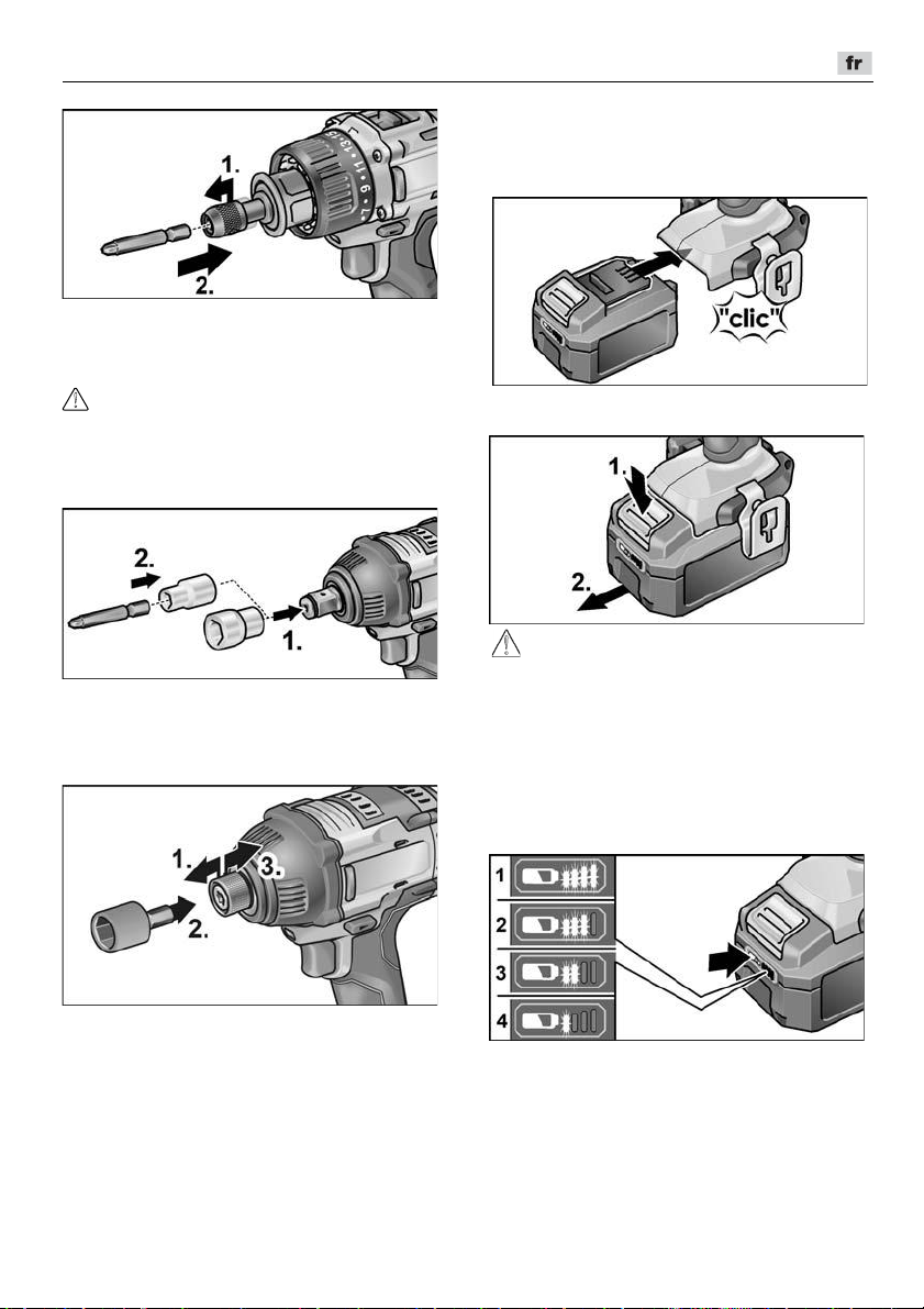
DD 2G 18.0-EC / PD 2G 18.0-EC / IW 1/2" 18.0-EC / ID 1/4" 18.0-EC
Installer/remplacer l'accumulateur
Enfoncez l'accumulateur chargé jusqu'à
l'encrantage complet dans l'outil
électrique.
Pour retirer l'outil, tirez le blocage de
l'outil vers l'arrière.
Changement d'outil
PRUDENCE !
Avant tout travail sur l'appareil électrique,
placez le sélecteur du sens de rotation (2)
en position centrale.
IW 1/2“ 18.0-EC :
Appuyer avec la clé à douille sur le carré
d'entraînement de la clé à chocs (1.).
Introduire l'outil dans la clé à douille (2.).
ID 1/4“ 18.0-EC :
Appuyez sur les boutons de déver-
rouillage (1.) et retirez l'accumulateur (2.).
PRUDENCE !
En cas de non-utilisation, protégez les
contacts de l'accumulateur. Les pièces
métalliques mal fixées peuvent courtcircuiter les contacts, il y a un risque
d'explosion et d'incendie !
Niveau de charge de l'accumulateur
En appuyant sur le bouton, il est possible
de contrôler sur les LED le niveau de
charge de l'accumulateur.
Tirez le blocage de l'outil vers l'avant (1.)
et engagez l'outil jusqu'en butée (2.).
Relâchez le blocage de l'outil.
Pour retirer l'outil, tirez le blocage de
l'outil vers l'arrière (3.).
Le voyant s'éteint au bout de 5 secondes.
Si l'une des LED clignote, l'accumulateur doit
être rechargé. Si, après avoir appuyé sur le
bouton, aucune LED ne s'allume, l'accumulateur est défectueux et doit être remplacé.
37
Page 38

DD 2G 18.0-EC / PD 2G 18.0-EC / IW 1/2" 18.0-EC / ID 1/4" 18.0-EC
Sélection du sens de rotation
PRUDENCE !
Ne modifiez le sens de rotation de l’outil
électrique que lorsque celui-ci est immobile.
Amenez le sélecteur du sens de rotation
sur la position requise :
– Gauche : dans le sens antihoraire
(enlever les vis, desserrer les vis)
– Droite : sens horaire
(percer, visser, serrer les vis)
– Milieu : cran anti-enclenchement
(changement d'outil, pour tous les
travaux sur l'outil électrique)
Mode (PD 2G 18.0-EC uniquement)
PRUDENCE !
Ne modifiez le mode de l’outil électrique que
lorsque celui-ci est immobile.
Placez la bague pivotante pour le mode
dans la position nécessaire.
Sélection du couple
PRUDENCE !
Ne modifiez le couple de l’outil électrique
que lorsque celui-ci est immobile.
Placez la bague pivotante pour le régla-
ge du couple dans la position nécessaire.
DD 2G 18.0-EC :
1–23 : vissage
: perçage
REMARQUE
En position de perçage, l'accouplement
à friction est désactivé.
PD 2G 18.0-EC :
Sélection de la vitesse
PRUDENCE !
Ne modifiez la vitesse de l’outil électrique
que lorsque celui-ci est immobile.
: perçage
: vissage
: perçage à percussion
38
Placez le sélecteur dans la position
nécessaire :
1 : vitesse lente, couple élevé
2 : vitesse rapide, couple faible
Page 39

DD 2G 18.0-EC / PD 2G 18.0-EC / IW 1/2" 18.0-EC / ID 1/4" 18.0-EC
Enclencher l’appareil électrique
Enclenchement de l’appareil :
Appuyez sur l’interrupteur.
L'interrupteur de l'outil électrique permet
d'augmenter progressivement la vitesse
jusqu'à la valeur maximale.
Coupure de l’appareil :
Relâchez l’interrupteur.
REMARQUE
–
L'outil électrique dispose d'un frein qui
arrête l'outil installé immédiatement
après relâchement.
–
En cas d'utilisation prolongée de l'outil
électrique, il est conseillé de travailler
principalement avec l'interrupteur
entièrement activé.
Allumer/éteindre l'éclairage du
poste de travail
1. P
ositionner l'interrupteur de sélection de
sens (2) sur « en avant » ou « en arrière ».
2. Appuyer sur l'interrupteur marche/
arrêt (1) de l'outil électrique
– L'éclairage du poste de travail s'allume
3. Relâcher l'interrupteur marche/arrêt (1)
de l'outil électrique
– L'éclairage du poste de travail s'éteint
automatiquement après env. 10 s
Présélection du régime et du couple
IW 1/2“ 18.0-EC / ID 1/4“ 18.0-EC
Modifier le régime/le couple
1. Allumer l'interrupteur marche/arrêt (1)
2. Appuyer brièvement sur le sélecteur de
mode (env. 0,5 s).
– Une LED s'allume – Couple :
IW 1/2“ 18.0-EC :
ID 1/4“ 18.0-EC :
3. Appuyer brièvement sur le sélecteur
de mode
– Deux LED s'allument – Couple :
IW 1/2“ 18.0-EC :
ID 1/4“ 18.0-EC :
4. Appuyer brièvement sur le sélecteur
de mode
– Trois LED s'allument – Couple :
IW 1/2“ 18.0-EC :
ID 1/4“ 18.0-EC :
5. Appuyer brièvement sur le sélecteur
de mode
– Une LED s'allume – Le couple
repasse à :
IW 1/2“ 18.0-EC : 150 Nm
ID 1/4“ 18.0-EC : 60 Nm
Le couple peut être à nouveau augmenté
comme décrit.
Lorsque l'outil électrique fonctionne dans
le sens « en avant » – avec un régime
sélectionné – les LED situées dans le pied
s'éteignent automatiquement.
150 Nm / 1500 min
60 Nm / 1500 min
180 Nm / 2000 min
105 Nm / 2000 min
250 Nm / 2500 min
225 Nm / 2500 min
-1
-1
-1
-1
-1
-1
Passer du mode choc unique au mode
clé à chocs
Appuyer sur le sélecteur de mode
env. 1,5 s.
– La LED d'indication de mode s'allume
– Le mode choc unique est actif
– La LED d'indication de mode ne
s'allume pas – Le mode clé à chocs
est actif.
39
Page 40

DD 2G 18.0-EC / PD 2G 18.0-EC / IW 1/2" 18.0-EC / ID 1/4" 18.0-EC
Travailler avec l’appareil électrique
PRUDENCE !
Avant tout travail sur l'outil électrique,
placez le sélecteur du sens de rotation (2)
en position centrale.
REMARQUE
Afin de faciliter le maniement lors du
vissage, l'embout de vissage peut être
inséré directement dans le logement d'outil
de l'appareil.
1. Montez le porte-outil (mandrin de
perçage interchangeable, adaptateur
angulaire, adaptateur porte-embout).
2. Installez l'accumulateur.
3. Mettez l'outil (forets, embouts de
vissage, porte-embouts) en place.
4. Réglez le mode de fonctionnement en
fonction de la tâche (uniquement PD...).
5. Placez la sélection du couple dans la
position nécessaire.
6. Réglez la vitesse dans la position
nécessaire.
7. Réglez le sens de rotation nécessaire.
8. Saisissez l'outil électrique d'une main
sur la poignée et placez-vous en position de travail. Lorsque le moteur est en
marche, n'actionnez en aucun cas le
pré-sélecteur de sens de rotation ou le
réglage du couple !
9. Allumez l’appareil.
Après la fin du travail :
10. Relâchez l’interrupteur.
11. Mettez le sélecteur du sens
de rotation (2) en position centrale.
Chargeur
1 Compartiment pour accumulateur
2 Contacts
3 Orifices d'aération
4 Affichage de l'état de fonctionnement
5 Cordon d'alimentation avec prise
Le chargeur CA 10.8/18.0 est conçu pour le
chargement des accumulateurs FLEX
de types
– AP 10.8 (2,5 Ah),
– AP 18.0 (2,5 Ah),
– AP 10.8 (5,0 Ah),
– AP 18.0 (5,0 Ah).
Remarque pour prolonger la durée de
vie de l'accumulateur
PRUDENCE !
–
Ne chargez jamais les accumulateurs
à des températures inférieures à 0 °C
ou supérieures à 55 °C.
–
Ne rechargez pas les accumulateurs
dans un environnement à l'humidité
ou la température ambiante élevée.
–
Ne couvrez pas les accumulateurs
et le chargeur pendant le processus
de chargement.
–
Débranchez la fiche de l'appareil une fois
le rechargement terminé.
Pendant le rechargement, l'accumulateur et
l'appareil chauffent. Cela est normal !
Les accumulateurs lithium-ion ne
présentent pas d'"effet de mémoire" connu.
40
Page 41
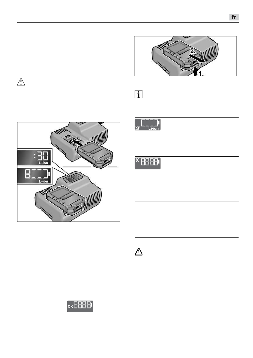
DD 2G 18.0-EC / PD 2G 18.0-EC / IW 1/2" 18.0-EC / ID 1/4" 18.0-EC
Néanmoins, un accumulateur doit être
entièrement déchargé avant d'être rechargé
et le rechargement doit toujours être
effectué en intégralité.
En cas de non-utilisation prolongée, les
accumulateurs doivent être stockés
partiellement chargés et refroidis.
Processus de chargement
PRUDENCE !
Placez uniquement des accumulateurs
d'origine dans le chargeur fourni.
Branchez la prise de l'appareil.
Le rétro-éclairage de l'écran s'allume
en vert pendant 2 secondes et s'éteint
à nouveau. OK s'affiche.
Insérez complètement l'accumulateur
dans le chargeur jusqu'à encrantage.
– Sur l'écran, alternent la durée restante
de chargement (jusqu'au
rechargement complet de
l'accumulateur) et une représentation
graphique du niveau de charge.
– Le rétro-éclairage de l'écran est
orange lorsque l'accumulateur est
chargé à moins de 80 %.
– À partir de 80 %, l'affichage est vert et
OK s'affiche.
L'accumulateur est complètement chargé
lorsque l'affichage apparaît.
Le rétro-éclairage vert s'éteint après un
court instant.
Retirez l'accumulateur du chargeur.
Débranchez la fiche mâle de la prise
de courant.
REMARQUE
Si, après avoir retiré l'accumulateur du
chargeur, l'écran clignote, il y a un défaut au
niveau de l'accumulateur ou du chargeur.
L'affichage clignote lentement.
Rétro-éclairage orange.
L'accumulateur est trop chaud ou trop froid.
Lorsque l'accumulateur atteint la
température de charge (0°C...55°C), le
chargement commence.
L'affichage clignote rapidement.
Rétro-éclairage rouge.
Retirez l'accumulateur du chargeur ou
réinstallez-le. Avec un tel affichage,
l'accumulateur est défectueux. Remplacez
l'accumulateur ou faites-le contrôler dans
un atelier spécialisé.
Si le même message d'erreur survient avec
un autre accumulateur, le défaut vient du
chargeur. Faites contrôler le chargeur par
un atelier spécialisé.
Maintenance et nettoyage
Nettoyage
AVERTISSEMENT!
Lors du travail des métaux dans des
conditions d’emploi intensives, de la
poussière électroconductrice peut se
déposer à l’intérieur du boîtier de l’appareil.
Nettoyez régulièrement l'outil électrique et
les orifices d'aération. La fréquence des
nettoyages dépend du matériau et de la
durée d’utilisation.
Nettoyez régulièrement l’intérieur du boîtier
et le moteur à l’aide d’air comprimé sec.
Faites fonctionner l'outil électrique ainsi.
41
Page 42

DD 2G 18.0-EC / PD 2G 18.0-EC / IW 1/2" 18.0-EC / ID 1/4" 18.0-EC
Chargeur
AVERTISSEMENT !
Avant d’effectuer tous travaux sur le chargeur,
débranchez la fiche mâle de la prise de
courant. N’utilisez ni eau ni produits de
nettoyage liquides.
Retirez la saleté et la poussière du carter
avec une brosse ou un chiffon sec.
Réparations
Ne confiez les réparations qu’à un atelier de
SAV agréé par le fabricant.
Pièces de rechange et accessoires
D’autres accessoires, notamment les outils
installés, figurent dans le catalogue du
fabricant.
Vous trouverez des vues éclatées et des
listes de pièces de rechange sur notre site
Web : www.flex-tools.com
Transport
La quantité équivalente de lithium des accumulateurs inclus à la livraison est inférieure
aux limites applicables. Par conséquent,
l'accumulateur en tant que pièce détachée
et l'outil électrique tel que livré ne sont pas
soumis aux réglementations nationales ou
internationales relatives aux matières
dangereuses. En cas de transport de plusieurs appareils avec des accumulateurs
Lithium-ion, ces réglementations peuvent
être applicables et nécessiter des mesures
de sécurité particulières (par ex. pour
l'emballage). Dans ce cas, informez-vous
sur les réglementations applicables dans le
pays d'utilisation.
Conformité
Nous déclarons sous notre responsabilité
exclusive que le produit décrit à la rubrique
« Données techniques » se conforme aux
normes ou aux documents normatifs
suivants :
EN 62841 conformément aux dispositions
des directives 2014/30/UE, 2006/42/CE,
2011/65/UE.
Responsables de la documentation technique :
FLEX-Elektrowerkzeuge GmbH, R & D
Bahnhofstrasse 15, D-71711 Steinheim/Murr
18.12.2017
FLEX-Elektrowerkzeuge GmbH
Bahnhofstrasse 15, D-71711 Steinheim/Murr
Consignes pour la mise au rebut
AVERTISSEMENT !
Rendez inutilisables les outils électriques
usagés avant leur mise au rebut :
–
les outils électriques alimentés par le
réseau électrique en retirant le câble
d'alimentation,
–
les outils électriques alimentés par un
accumulateur en retirant ce dernier.
Pays de l’UE uniquement.
Ne jetez pas les outils électriques avec les
déchets domestiques ! Conformément à la
directive européenne 2012/19/UE visant les
appareils électriques et électroniques usagés,
et à sa transposition en droit national, les outils électriques ne servant plus devront être
collectés séparément et introduits dans un circuit de recyclage respectueux de
l’environnement.
42
Page 43

DD 2G 18.0-EC / PD 2G 18.0-EC / IW 1/2" 18.0-EC / ID 1/4" 18.0-EC
Récupérer les matières premières
plutôt que de les jeter à la poubelle.
Il est recommandé d'introduire l’appareil, ses
accessoires et l’emballage dans un circuit de
recyclage adapté à l’environnement. Les
pièces en plastique comportent un marquage
pour permettre leur tri avant recyclage.
AVERTISSEMENT !
Ne jetez pas les accus / batteries dans la
poubelle des déchets domestiques ; ne les
jetez ni au feu ni dans l’eau. Ne tentez pas
d’ouvrir des accus qui ne servent plus.
Les accus/batteries doivent être collectés,
recyclés ou éliminés dans le respect de
l'environnement.
Pays de l’UE uniquement.
Conformément à la directive européenne
2006/66/CE les accus / batteries
défectueux ou épuisés devront être collectés
séparément et introduits dans un circuit de
recyclage respectueux de l’environnement.
REMARQUE
Pour connaître les possibilités de mise au
rebut, veuillez consulter votre revendeur
spécialisé.
Exclusion de responsabilité
Le fabricant et son représentant ne pourront
être tenus responsables des dommages
et du bénéfice perdu en raison d’une interruption du fonctionnement de l’affaire,
provoqués par le produit ou par l’impossibilité
de l’utiliser.
Le fabricant et son représentant ne pourront
être tenus responsables des dommages provoqués par une utilisation inexperte du produit
ou par son utilisation en association avec les
produits d’autres fabricants.
43
Page 44

DD 2G 18.0-EC / PD 2G 18.0-EC / IW 1/2" 18.0-EC / ID 1/4" 18.0-EC
Indice
Simboli utilizzati . . . . . . . . . . . . . . . . . . . 44
Simboli sull’apparecchio. . . . . . . . . . . . . 44
Per la vostra sicurezza . . . . . . . . . . . . . 44
Rumore e vibrazione . . . . . . . . . . . . . . . 46
Dati tecnici . . . . . . . . . . . . . . . . . . . . . . . 47
Guida rapida . . . . . . . . . . . . . . . . . . . . . 49
Istruzioni per l’uso . . . . . . . . . . . . . . . . . 50
Manutenzione e cura . . . . . . . . . . . . . . . 56
Trasporto . . . . . . . . . . . . . . . . . . . . . . . . 57
Conformità . . . . . . . . . . . . . . . . . . . . 57
Istruzioni per la rottamazione e lo
smaltimento . . . . . . . . . . . . . . . . . . . . . . 57
Esclusione della responsabilità . . . . . . . 58
Simboli utilizzati
ATTENZIONE!
Indica un pericolo imminente. In caso
d’inosservanza dell’avvertenza, pericolo
di morte o di ferite gravi.
PRUDENZA!
Indica una situazione eventualmente
pericolosa. In caso d’inosservanza
dell’avviso, pericolo di ferite o danni
materiali.
AVVERTENZA
Indica consigli per l’impiego ed informazioni
importanti.
Simboli sull’apparecchio
Prima della messa in funzione
leggere le istruzioni per l’uso!
Indossare occhiali protettivi!
Trasformatore di sicurezza
resistente al cortocircuito
Proteggere la batteria dal calore,
ad es. prolungata esposizione ai
raggi solari, e dal fuoco.
Sussiste pericolo di esplosione.
Non gettare la batteria nel fuoco.
Sussiste pericolo di esplosione.
L’apparecchio è idoneo solo
all’utilizzo in ambienti chiusi. Non
esporre l’apparecchio alla pioggia.
Conservare l’elettroutensile e le
batterie in un luogo asciutto.
Avvertenze per lo smaltimento
(vedere pag. 57)!
Per la vostra sicurezza
ATTENZIONE!
Leggere tutte le avvertenze di sicurezza,
le istruzioni con relative illustrazioni e le
specifiche fornite con l’utensile elettrico.
La mancata ottemperanza alle avvertenze
e alle istruzioni può dare luogo a scosse
elettriche, a incendi e/o a lesioni serie.
Conservare tutte le avvertenze di sicurezza
e le istruzioni per poterle consultare in
futuro.
Prima di usare l’elettroutensile, leggere
e rispettare i documenti elencati di seguito:
–
queste istruzioni per l’uso,
–
le «Istruzioni di sicurezza generali» per
l’uso di elettroutensili presenti nel
fascicolo allegato (Scritti N°: 315.915),
–
le regole e le norme per la prevenzione
degli infortuni vigenti nel luogo d’impiego.
Questo elettroutensile è costruito secondo
lo stato dell’arte e le regole tecniche di
sicurezza riconosciute.
Tuttavia dal suo impiego possono derivare
pericoli per l’incolumità e la vita
dell’utilizzatore e di terzi, nonché danni alla
macchina o ad altri beni materiali.
Usare l’elettroutensile solo
–
per l’uso regolare previsto,
–
in perfetto stato tecnico di sicurezza.
Eliminare immediatamente i guasti che
pregiudicano la sicurezza.
44
Page 45

DD 2G 18.0-EC / PD 2G 18.0-EC / IW 1/2" 18.0-EC / ID 1/4" 18.0-EC
Utilizzo conforme alle finalità d’uso
Il trapano avvitatore a batteria
DD 2G 18.0-EC è concepito
– per l’impiego professionale nell’industria e
nell’artigianato,
– per l’avvitamento e lo svitamento di viti,
– per la foratura di legno, metallo, ceramica
e materiale sintetico.
Il trapano-avvitatore a percussione
a batteria PD2G18.0-EC è concepito
– per l’impiego professionale nell’industria e
nell’artigianato,
– per l’avvitamento e lo svitamento di viti,
– per la foratura di legno, metallo, ceramica
e materiale sintetico,
– per la foratura a percussione in laterizio,
muratura e pietra.
L’avvitatore a percussione a batteria
IW 1/2" 18.0-EC / ID 1/4" 18.0-EC è concepito
– per l’impiego professionale nell’industria e
nell’artigianato,
– per il serraggio e la svitatura di dadi e viti
delle dimensioni indicate.
Avvertenza di sicurezza per trapani
e avvitatori
Quando si eseguono lavori durante
i quali l’utensile montato o la vite
potrebbero toccare linee elettriche
nascoste oppure il cavo di alimentazione
dell’apparecchio, afferrare
l’elettroutensile solo sulle superfici di
presa isolate. Il contatto della vite con una
linea elettrica sotto tensione può mettere
sotto tensione anche le parti metalliche
dell’elettroutensile e provocare una scossa
elettrica.
Utilizzare le impugnature supplementari,
ove fornite in dotazione insieme
all’elettroutensile. La perdita del controllo
può causare lesioni.
Utilizzare idonei rilevatori per sondare
la presenza di linee di alimentazione
nascoste, o consultare la locale società
di fornitura. Il contatto con linee elettriche
può causare incendi e scosse elettriche.
Il danneggiamento di una tubazione del
gas può causare un’esplosione. La
penetrazione in una conduttura dell’acqua
provoca danni alle cose.
Se l’utensile montato si blocca, spegnere
subito l’elettroutensile. Occorre essere
pronti alle elevate coppie di reazione che
causano un contraccolpo. L’utensile
montato si blocca se:
– l’elettroutensile viene sovraccaricato
oppure
– resta incastrato nel pezzo in lavorazione.
Afferrare saldamente l’elettroutensile.
Eseguendo il serraggio o il rilascio delle viti,
possono verificarsi per breve tempo
elevate coppie di reazione.
Bloccare il pezzo da lavorare. Un pezzo
da lavorare fissato saldamente in un
dispositivo di bloccaggio oppure in una
morsa è tenuto con sicurezza maggiore
che con la sola mano.
Prima di riporre l’elettroutensile,
attendere che si sia completamente
arrestato. L’utensile montato può restare
agganciato ad oggetti e,
conseguentemente, si può perdere il
controllo dell’elettroutensile.
Utilizzare solo batterie originali, con la
tensione indicata sulla targhetta del tipo
dell’elettroutensile. In caso di utilizzo di
altre batterie, ad es. imitazioni, batterie
manipolate o di altri produttori, sussiste il
pericolo di infortuni e danni alle cose a
causa dell’esplosione delle batterie.
Avvertenze di sicurezza
supplementari per il trapanoavvitatore a percussione (PD ...)
Effettuando forature a percussione,
utilizzare un dispositivo di protezione
dell’udito. L’effetto del rumore può causare
la perdita dell’udito.
Avvertenze di sicurezza per la
manipolazione delle batterie
Non aprire mai la batteria. Pericolo
di cortocircuito.
Proteggere la batteria dal calore, ad es.
dalla prolungata esposizione ai raggi
solari, dal fuoco, dall’acqua e
dall’umidità. Sussiste pericolo di
esplosione.
45
Page 46

DD 2G 18.0-EC / PD 2G 18.0-EC / IW 1/2" 18.0-EC / ID 1/4" 18.0-EC
In caso di danneggiamento ed utilizzo
improprio, dalla batteria possono
fuoriuscire vapori. Provvedere al ricambio
di aria e, in caso di malessere, rivolgersi a
un medico. I vapori possono irritare le vie
respiratorie.
In caso d’impiego non corretto, dalla
batteria possono fuoriuscire liquidi.
Evitarne il contatto. In caso di contatto
accidentale, risciacquare con acqua.
Qualora il liquido dovesse entrare in
contatto con gli occhi, chiedere immediato
consiglio al medico. Il liquido fuoriuscito
dalla batteria può causare irritazioni
cutanee o bruciature.
Caricare la batteria esclusivamente con
caricabatterie consigliati dal produttore.
Se un caricabatterie previsto per un
determinato tipo di batterie viene utilizzato
con batterie di tipo diverso, sussiste
pericolo di incendio.
La batteria può essere danneggiata da
oggetti appuntiti, come ad esempio chiodi
o cacciaviti, oppure se viene esercitata una
forza dall’esterno. In tali casi può verificarsi
un cortocircuito interno e la batteria può
bruciare, produrre fumo, esplodere
o surriscaldarsi.
Caricabatteria
Controllare sempre che la tensione di
rete corrisponda alla tensione indicata
sulla targhetta del tipo del caricabatteria.
La spina del caricabatteria deve essere
adatta alla presa. Evitare assolutamente
di apportare modifiche alla spina.
Non impiegare spine adattatrici assieme
ad utensili con collegamento a terra.
Le spine non modificate e le prese adatte
allo scopo riducono il rischio di scosse
elettriche.
Impiegare il caricabatteria solo in
ambienti asciutti ed evitare il contatto con
umidità e pioggia.
L’eventuale penetrazione d’acqua nel
caricabatteria aumenta il pericolo di scosse
elettriche.
Non utilizzare mai il caricabatteria se
il cavo, la spina o l’apparecchio stesso
sono stati danneggiati per effetto di
un’azione esterna. Portare il caricabatteria
alla più vicina officina specializzata.
Non aprire in nessun caso il
caricabatteria. In presenza di un guasto,
rivolgersi ad un’officina specializzata.
Non appoggiare alcun oggetto sul
caricabatteria e non riporre il
caricabatteria su superfici morbide.
Sussiste pericolo di incendio.
Avvertenze di sicurezza speciali
Prima di iniziare qualunque lavoro
sull’elettroutensile, portare il preselettore
del senso di rotazione (2) in posizione
centrale.
Azionare il preselettore del senso di
rotazione (2) o il dispositivo di
regolazione della coppia (5) con
l’utensile fermo.
Per contrassegnare l’elettroutensile
usare solo targhette adesive.
Non praticare fori nella carcassa.
Rumore e vibrazione
AVVERTENZA
I valori di rumore e vibrazione sono stati
rilevati secondo EN 62841. I valori sono
riportati nella tabella «Dati tecnici».
ATTENZIONE!
I valori di misura indicati sono validi solo per
apparecchi nuovi. Nell’impiego quotidiano
i valori di rumore e vibrazione cambiano.
AVVERTENZA
Il livello di vibrazioni indicato in queste
istruzioni è stato misurato conformemente ad
un procedimento di misura standardizzato in
EN 62841 e può essere utilizzato per il
confronto tra elettroutensili. Tale procedimento è idoneo anche per una valutazione
temporanea della sollecitazione da vibrazioni.
Il livello di vibrazioni indicato rappresenta gli
impieghi principali dell’elettroutensile.
46
Page 47

DD 2G 18.0-EC / PD 2G 18.0-EC / IW 1/2" 18.0-EC / ID 1/4" 18.0-EC
Se tuttavia l’elettroutensile viene impiegato
per altri usi, con utensili non idonei o in
condizioni di manutenzione insufficiente,
il livello di vibrazioni può differire.
Questo può aumentare notevolmente
la sollecitazione da vibrazioni per tutta
la durata del lavoro.
Per
un’esatta stima della sollecitazione da
vibrazioni si devono considerare anche i tempi
Per proteggere l’operatore dall’effetto delle
vibrazioni, stabilire misure di sicurezza
aggiuntive, come ad esempio: manutenzione
dell’elettroutensile e degli utensili impiegati,
riscaldamento delle mani, organizzazione
delle procedure di lavoro.
PRUDENZA!
In caso di pressione acustica superiore
a 85 dB(A) indossare la protezione acustica.
nei quali l’apparecchio è spento oppure è in
funzione ma non è effettivamente impiegato.
Questo può ridurre notevolmente la sollecitazione da vibrazioni per tutta la durata del
lavoro.
Dati tecnici
Apparecchio DD 2G
18.0-EC
Modello Trapano-
avvitatore
Batteria AP 18.0/2,5
Tempo di ricarica (a
seconda dello stato di
carica)
– AP 18.0/2,5
– AP 18.0/5,0
min
min
Coppia, massima
– caso vite morbida
– caso vite dura
Nm
Nm
56
90
Livelli di coppia 20 24 –
Numero giri a vuoto
– livello 1
– livello 2
– livello 3
Numero di colpi
– livello 1
– livello 2
– livello 3
min
min
min
min
min
min
-1
-1
-1
-1
-1
-1
0...600
0...2300
–
–
–
–
Mandrino mm 1,5–13 –
PD 2G
18.0-EC
Trapano-
avvitatore a
percussione
AP 18.0/5,0
56
90
0...600
0...2300
–
0...9600
0...37000
–
IW 1/2"
18.0-EC
Avvitatore a
percussione
0–40
0–45
–
250
1500
2000
2500
1300
2800
3300
ID 1/4"
18.0-EC
Avvitatore a
percussione
–
225
1500
2000
2500
1300
2800
3300
47
Page 48

DD 2G 18.0-EC / PD 2G 18.0-EC / IW 1/2" 18.0-EC / ID 1/4" 18.0-EC
Apparecchio DD 2G
18.0-EC
Modello Trapano-
avvitatore
PD 2G
18.0-EC
Trapano-
avvitatore a
IW 1/2"
18.0-EC
Avvitatore a
percussione
percussione
Max. diametro di foratura
– nel legno
– nell’acciaio
– nella muratura
mm
mm
mm
60
13
16
60
13
16
–
–
–
Peso secondo la «EPTAprocedure 01/2003»
kg 1,5 1,6 1,1 1,1
(senza batteria)
Peso batteria 2,5 Ah
5,0 Ah
kg
kg
0,4
0,7
Livello di pressione acustica
ponderato A
Livello di pressione
acustica L
pA
Livello di potenza
acustica L
WA
dB(A) 78* 78* / 95** 91*** 91***
dB(A) 89* 89* / 106** 102*** 102***
Incertezza K db 3,0
Valori totali di vibrazione (somma vettoriale di tre direzioni)
Valore totale di vibrazione a
– foratura nel metallo
– foratura a percussione
nel calcestruzzo
– avvitatura
Incertezza K
* foratura nel metallo / ** foratura a percussione nel calcestruzzo / *** avvitamento a percussione
in caso di ....
h
2
m/s
2
m/s
2
m/s
2
m/s
<2,5 <2,5 – –
– 15,5 – –
<2,5 <2,5 18,5*** 18,5***
1,5
ID 1/4"
18.0-EC
Avvitatore a
percussione
–
–
–
48
Page 49

DD 2G 18.0-EC / PD 2G 18.0-EC / IW 1/2" 18.0-EC / ID 1/4" 18.0-EC
Guida rapida
In questo libretto di istruzioni sono descritti diversi elettroutensili. La rappresentazione grafica
può differire nei dettagli dall’elettroutensile acquistato.
1 Interruttore
Per accendere e spegnere e per
accelerare fino alla massima velocità
di rotazione
2 Preselettore del senso di rotazione
3 Selettore della velocità
4 Anello rotante per la modalità di
funzionamento (solo PD ...)
5 Anello rotante per la regolazione della
coppia di serraggio
6 Attacco utensile
7 Illuminazione del punto di lavoro
8 Impugnatura
9 Campo comandi con livelli di velocità
10 Vano inserimento batteria
11 Supporto angolare con anello di
sbloccaggio
12 Mandrino intercambiabile con anello
di sbloccaggio
13 Supporto portabit con anello di
sbloccaggio
14 Impugnatura supplementare
15 Batteria al litio (2,5 Ah)
16 Tasto di sbloccaggio per la batteria
17 Indicatore della condizione della
batteria
18 Batteria al litio (5,0 Ah)
19 Fermaglio per attacco alla cintura
20 Vite di fissaggio
21 Supporto per bit
49
Page 50

DD 2G 18.0-EC / PD 2G 18.0-EC / IW 1/2" 18.0-EC / ID 1/4" 18.0-EC
Istruzioni per l’uso
Prima della messa in funzione
Disimballare elettroutensile ed accessori
e controllare la completezza della
fornitura ed eventuali danni di trasporto.
Fissare la fibbia e il supporto per bit con
la vite in dotazione.
AVVERTENZA
Alla consegna le batterie non sono completamente cariche. Prima del primo impiego,
caricare le batterie completamente. Vedere
«Caricabatteria/Processo di carica».
Montaggio/smontaggio
dell’impugnatura supplementare
(PD/DD 2G 18.0-EC)
PRUDENZA!
Utilizzare le impugnature supplementari,
ove fornite in dotazione insieme
all’elettroutensile. La perdita del controllo
può causare lesioni.
Mandrino intercambiabile BF 18.0-EC
PRUDENZA!
Prima di iniziare qualunque lavoro
sull’elettroutensile, portare il preselettore del
senso di rotazione (2) in posizione centrale.
Montaggio
Tirare in avanti l’anello di sbloccaggio (1.)
e premere il mandrino intercambiabile sul
portautensile fino all’arresto (2.).
Rilasciare l’anello di sbloccaggio.
Controllare che il mandrino sia scattato
in sede.
Smontaggio
Tirare in avanti l’anello di sbloccaggio
e rimuovere il mandrino
Inserimento dell’utensile
Nel mandrino è possibile fissare in sicurezza punte con un diametro di 1,5–13 mm,
bit di avvitamento
Tenere fermo l’elettroutensile con una
mano e girare il mandrino con l’altra mano.
– Per aprire ulteriormente il mandrino,
ruotarlo in senso antiorario.
– Per chiudere il mandrino, ruotarlo in
senso orario.
½" e portabit ½".
.
50
Inserire l’utensile.
Chiudere il mandrino completamente.
AVVERTENZA
Eseguire una prova di funzionamento, per
controllare che l’utensile sia centrato
correttamente.
Page 51

DD 2G 18.0-EC / PD 2G 18.0-EC / IW 1/2" 18.0-EC / ID 1/4" 18.0-EC
Attacco angolare WV 18.0-EC
PRUDENZA!
Prima di iniziare qualunque lavoro
sull’elettroutensile, portare il preselettore del
senso di rotazione (2) in posizione centrale.
L’attacco angolare facilita il lavoro in punti di
difficile accesso. L’attacco angolare può
essere fatto scattare in differenti posizioni,
con spostamenti di 30°.
Montaggio
Tirare in avanti l’anello di sbloccaggio (1.)
e premere l’attacco angolare sul
portautensile (2.) fino all’arresto.
Far scattare l’attacco angolare nella
posizione angolare desiderata.
Rilasciare l’anello di sbloccaggio.
Controllare il corretto scatto in sede.
Smontaggio
Tirare in avanti l’anello di sbloccaggio
e rimuovere l’attacco angolare.
Inserimento dell’utensile
L’attacco angolare dispone di un portautensile
da
½". Nel portautensile vengono fissati in
sicurezza bit di avvitamento e portabit.
Sull’attacco angolare è anche possibile
montare il mandrino intercambiabile (vedere
«Mandrino intercambiabile BF 18.0-EC»)
o il portabit (vedere «Attacco portabit
BV 18.0-EC»).
Attacco portabit BV 18.0-EC
PRUDENZA!
Prima di iniziare qualunque lavoro
sull’elettroutensile, portare il preselettore del
senso di rotazione (2) in posizione centrale.
Montaggio
Tirare in avanti l’anello di sbloccaggio (1.)
e premere l’attacco portabit sul
portautensile (2.) fino all’arresto.
Rilasciare l’anello di sbloccaggio.
Controllare il corretto scatto in sede.
Smontaggio
Tirare in avanti l’anello di sbloccaggio
e rimuovere l’attacco portabit.
Inserimento dell’utensile
L’attacco portabit dispone di un
portautensile da
vengono fissati in sicurezza bit di
avvitamento.
Tirare in avanti l’elemento di bloccaggio
utensili (1.) e premere l’utensile fino
all’arresto (2.).
Rilasciare l’elemento di bloccaggio utensili.
½". Nel portautensile
Per la rimozione dell’utensile tirare
l’elemento di bloccaggio utensili in
direzione posteriore.
51
Page 52

DD 2G 18.0-EC / PD 2G 18.0-EC / IW 1/2" 18.0-EC / ID 1/4" 18.0-EC
Cambio utensile
PRUDENZA!
Prima di iniziare qualunque lavoro
sull’elettroutensile, portare il preselettore del
senso di rotazione (2) in posizione centrale.
IW 1/2“ 18.0-EC:
Premere la bussola sul supporto quadro
dell'avvitatore a massa battente (1.).
Inserire l'utensile nella bussola (2.).
ID 1/4“ 18.0-EC:
Tirare in avanti l’elemento di bloccaggio
utensili (1.) e premere l’utensile fino
all’arresto (2.).
Rilasciare l’elemento di bloccaggio utensili.
Per la rimozione dell’utensile tirare
l’elemento di bloccaggio utensili in
direzione posteriore (3.).
Inserimento/sostituzione della batteria
Spingere la batteria carica fino
a farla scattare completamente
nell’elettroutensile.
Per rimuovere la batteria, premere i tasti di
sbloccaggio (1.) ed estrarre la batteria (2.).
PRUDENZA!
Quando la batteria non viene utilizzata,
proteggere i contatti. La minuteria metallica
sfusa può mettere in cortocircuito i contatti;
pericolo di esplosione e d’incendio!
Condizioni di carica della batteria
Premendo il tasto, è possibile controllare
il livello di carica della batteria
sull’indicatore a LED.
L’indicatore si spegne dopo 5 secondi.
Se uno dei LED lampeggia, la batteria deve
essere ricaricata. Se, dopo aver premuto il
tasto, non si accende alcun LED, la batteria
è guasta e deve essere sostituita.
Preselezione del senso di rotazione
PRUDENZA!
Modificare il senso di rotazione solo quando
l’elettroutensile è fermo.
52
Page 53

DD 2G 18.0-EC / PD 2G 18.0-EC / IW 1/2" 18.0-EC / ID 1/4" 18.0-EC
Portare il preselettore del senso di
rotazione sulla posizione desiderata:
– Verso sinistra: in senso antiorario
(per svitare o allentare le viti)
– Verso destra: in senso orario
(per forare, avvitare o serrare le viti)
– Posizione centrale: blocco dell’attiva-
zione (cambio utensile, per tutti i lavori
sull’elettroutensile)
Modo di funzionamento
(solo PD 2G 18.0-EC)
PRUDENZA!
Modificare il modo di funzionamento solo
con l’elettroutensile fermo.
Portare l’anello rotante per la selezione
del modo di funzionamento sulla
posizione desiderata.
: Foratura
: Avvitatura
: Foratura a percussione
Preselezione della coppia
PRUDENZA!
Modificare la coppia solo con
l’elettroutensile fermo.
Portare l’anello rotante per l’imposta-
zione della coppia di serraggio sulla
posizione desiderata.
DD 2G 18.0-EC:
AVVERTENZA
Nella posizione foratura il giunto di
sicurezza è disattivato.
PD 2G 18.0-EC:
Preselezione della velocità
PRUDENZA!
Modificare la velocità solo con
l’elettroutensile fermo.
Portare il selettore sulla posizione
desiderata:
1: bassa velocità, coppia elevata
2: alta velocità, coppia bassa
Accensione dell’elettroutensile
Accendere l’apparecchio:
Premere l’interruttore.
L’interruttore dell’elettroutensile consente di aumentare progressivamente il
numero di giri fino al valore massimo.
1–23: Avvitatura
: Foratura
Spegnere l’apparecchio:
Rilasciare l’interruttore.
53
Page 54

DD 2G 18.0-EC / PD 2G 18.0-EC / IW 1/2" 18.0-EC / ID 1/4" 18.0-EC
AVVERTENZA
–
L’elettroutensile dispone di un freno che
arresta l’utensile montato immediatamente dopo il rilascio dell’interruttore.
–
In caso d’impiego continuativo
dell’elettroutensile, occorre lavorare
principalmente con l’interruttore premuto
a fondo.
Accensione spegnimento della luce
per postazione di lavoro
1. Portare il selettore del senso di
rotazione (2) in posizione “avanti”
o “indietro”.
2. Premere l'interruttore on/off (1)
dell'elettroutensile
– L’illuminazione per la postazione di
lavoro si accende
3. Rilasciare l'interruttore on/off (1)
dell'elettroutensile
– L’illuminazione per la postazione di
lavoro si spegne automaticamente
dopo 10 s circa
Preselezione numero di giri e coppia
IW 1/2“ 18.0-EC / ID 1/4“ 18.0-EC
Commutazione numero di giri/coppia
1. Attivare l'interruttore on/off (1)
2. Premere brevemente l'interruttore di
modalità (circa 0,5 s).
– Si accende un LED – Coppia:
IW 1/2“ 18.0-EC:
ID 1/4“ 18.0-EC:
Premere brevemente l'interruttore di
modalità
– Si accendono due LED – Coppia:
IW 1/2“ 18.0-EC:
ID 1/4“ 18.0-EC:
150 Nm / 1500 giri/min
60 Nm / 1500 giri/min
180 Nm / 2000 giri/min
105 Nm / 2000 giri/min
-1
-1
-1
-1
3. Premere brevemente l'interruttore di
modalità
– Si accendono tre LED – Coppia:
IW 1/2“ 18.0-EC:
ID 1/4“ 18.0-EC:
4. Premere brevemente l'interruttore di
modalità
Si accende un LED – La coppia ritorna a:
–
IW 1/2“ 18.0-EC: 150 Nm
ID 1/4“ 18.0-EC: 60 Nm
La coppia può essere nuovamente
aumentata nel modo descritto.
In modalità di rotazione inversa
dell'elettroutensile (dispone di un solo
numero di giri) i LED presenti nel piedino
si spengono automaticamente.
250 Nm / 2500 giri/min
225 Nm / 2500 giri/min
-1
-1
Commutazione da modalità
percussione singola a modalità
avvitatore a massa battente:
Premere l'interruttore di modalità per
circa 1,5 s.
– Il LED indicatore di modalità è acceso
– È attiva la modalità percussione
singola
– Il LED indicatore di modalità non
è acceso – È attiva la modalità
avvitatore a massa battente.
Lavorare con l’elettroutensile
PRUDENZA!
Prima di iniziare qualunque lavoro
sull’elettroutensile, portare il preselettore
del senso di rotazione (2) in posizione
centrale.
AVVERTENZA
Per agevolare l’operazione di avvitamento,
il bit di avvitamento può anche essere
inserito direttamente nel portautensile
dell’apparecchio.
54
Page 55

DD 2G 18.0-EC / PD 2G 18.0-EC / IW 1/2" 18.0-EC / ID 1/4" 18.0-EC
Caricabatteria
1. Montare il supporto utensili (mandrino
intercambiabile, attacco angolare,
attacco portabit).
2. Inserire la batteria.
3. Inserire l’utensile (punta, bit di avvitamento, portabit).
4. Impostare la modalità d’esercizio a seconda del lavoro da eseguire (solo PD...).
5. Portare il selettore della coppia sulla
posizione desiderata.
6. Regolare la velocità sul livello desiderato.
7. Impostare il senso di rotazione
desiderato.
8. Con una mano afferrare l’elettroutensile
dall’impugnatura ed assumere la posizione di lavoro.
Con il motore attivo non azionare mai
l’interruttore di pre-selezione della
direzione di rotazione o la regolazione
della coppia!
9. Accendere l’apparecchio.
Alla fine del lavoro:
10. Rilasciare l’interruttore.
11. Portare il preselettore del senso di
rotazione (2) in posizione centrale.
1 Vano inserimento batteria
2Contatti
3 Fessure di ventilazione
4 Display per l’indicazione della
condizione di esercizio
5 Cavo di rete con spina di rete
Il caricabatteria CA 10.8/18.0 è concepito
per il caricamento di batterie FLEX dei tipi
– AP 10.8 (2,5 Ah),
– AP 18.0 (2,5 Ah),
– AP 10.8 (5,0 Ah),
– AP 18.0 (5,0 Ah).
Avvertenze per una lunga durata della
batteria
PRUDENZA!
–
Non caricare mai le batterie a temperature inferiori a 0 °C o superiori a 55 °C.
–
Non caricare mai le batterie in ambienti
con elevata umidità dell’aria o elevata
temperatura ambiente.
–
Durante il processo di carica non coprire
le batterie o il caricabatteria.
–
Una volta concluso il processo di carica
estrarre la spina di rete del caricabatteria.
Durante il processo di carica la batteria
e il caricabatteria si scaldano.
È un fenomeno normale!
Le batterie agli ioni di litio non soffrono del noto
«effetto memoria». Tuttavia la batteria
dovrebbe essere ricaricata solo quando
è completamente scarica e il processo di
ricarica dovrebbe essere concluso solo
quando la batteria è completamente ricaricata.
55
Page 56

DD 2G 18.0-EC / PD 2G 18.0-EC / IW 1/2" 18.0-EC / ID 1/4" 18.0-EC
Se le batterie restano inutilizzate per un lungo
periodo, caricarle parzialmente e conservarle
in un luogo freddo.
Processo di carica
PRUDENZA!
Inserire nel caricabatteria in dotazione solo
batterie originali.
Inserire la spina di rete del caricabatteria.
La retroilluminazione del display si
accende per 2 secondi a luce verde,
quindi si spegne. In questo modo il
display segnala OK.
Inserire la batteria completamente nel
caricabatteria fino allo scatto.
– Sul display vengono visualizzate
alternativamente la durata residua del
processo di carica (tempo mancante al
caricamento completo della batteria) e
l’illustrazione grafica dello stato di carica.
– La retroilluminazione del display è
accesa a luce arancione se la batteria
è carica in misura inferiore all’80%.
– A partire da una carica della batteria
dell’80%, il display è illuminato a luce
verde e viene indicato OK.
La batteria è completamente carica
quando compare l’indicazione
.
La retroilluminazione verde si spegne
dopo alcuni istanti.
Rimuovere la batteria dal caricabatteria.
Estrarre la spina d’alimentazione.
AVVERTENZA
Se, dopo l’inserimento della batteria nel
caricabatteria, il display lampeggia, è presente
un guasto della batteria o del caricabatteria.
Il display lampeggia lentamente.
Retroilluminazione arancione.
La batteria è troppo calda o troppo fredda.
Il processo di carica inizia quando la
batteria ha raggiunto la temperatura di
ricarica (0°C...55°C).
Il display lampeggia
velocemente.
Retroilluminazione rossa.
Estrarre la batteria dal caricabatteria
e reinserirla. Se l’indicazione permane
identica, la batteria è guasta. Sostituire la
batteria o farla controllare in un’officina
specializzata.
Se questa segnalazione di guasto si ripete
con un’altra batteria, è presente un difetto
del caricabatteria. Far controllare il
caricabatteria in un’officina specializzata.
Manutenzione e cura
Pulizia
ATTENZIONE!
Nella lavorazione di metalli, in caso
d’impiego in condizioni estreme, nell’interno
della carcassa può accumularsi polvere
conduttrice. Pulire l’elettroutensile e le
fessure di ventilazione periodicamente.
La frequenza dipende dal materiale lavorato
e dalla durata dell’uso.
Soffiare regolarmente con aria
compressa secca l’interno della carcassa
con il motore. Far contemporaneamente
funzionare l’elettroutensile.
56
Page 57

DD 2G 18.0-EC / PD 2G 18.0-EC / IW 1/2" 18.0-EC / ID 1/4" 18.0-EC
Caricabatteria
ATTENZIONE!
Prima di qualsiasi lavoro estrarre la spina di
rete. Non usare acqua o detergenti liquidi.
Rimuovere dalla carcassa lo sporco
e la polvere con un pennello o un panno
asciutto.
Riparazioni
Fare eseguire le riparazioni esclusivamente
da un’officina del servizio assistenza clienti
autorizzata dal produttore.
Ricambi ed accessori
Per altri accessori, specialmente utensili
montati, consultare i cataloghi del produttore.
Per i disegni esplosi e le liste dei ricambi
consultare il nostro sito: www.flex-tools.com
Trasporto
La quantità equivalente di litio contenuta
nelle batterie della fornitura rientra nei limiti
vigenti. Pertanto la batteria, come elemento
singolo e come elettro
in dotazione, non rientra nelle norme nazionali
o internazionali sulle merci pericolose
In caso di trasporto di più apparecchi con
batterie agli ioni di litio, tali norme possono
acquisire rilevanza e richiedere quindi misure
di sicurezza (ad es. per l’imballaggio).
Richiedere in tal caso informazioni sulle
norme in vigore nel Paese d’impiego.
utensile con accessori
.
Conformità
Dichiariamo sotto nostra esclusiva responsabilità che il prodotto descritto in «Dati tecnici»
è conforme alle seguenti norme o documenti
normativi:
EN 62841 conformemente alle norme delle
direttive 2014/30/UE, 2006/42/CE,
2011/65/UE.
Il responsabile della documentazione tecnica:
FLEX-Elektrowerkzeuge GmbH, R & D
Bahnhofstrasse 15, D-71711 Steinheim/Murr
18/12/2017; FLEX-Elektrowerkzeuge GmbH
Bahnhofstrasse 15, D-71711 Steinheim/Murr
Istruzioni per la rottamazione e lo
smaltimento
ATTENZIONE!
Prima dello smaltimento rendere
inutilizzabili gli elettroutensili dismessi:
–
in caso di elettroutensili alimentati mediante
cavo elettrico, rimuovendo il cavo di rete,
–
in caso di elettroutensili alimentati
a batteria, rimuovendo la batteria.
Solo per paesi dell’UE.
Non gettare elettroutensili nei rifiuti domestici!
Secondo la direttiva europea 2012/19/UE sui
rifiuti di apparecchiature elettriche ed elettroniche e sua conversione nel diritto nazionale,
gli elettroutensili dismessi devono essere
raccolti separatamente ed avviati ad un
riciclaggio ecologico.
Recupero di materie prime anziché
smaltimento di rifiuti.
Consegnare l’apparecchio, gli accessori
e l’imballaggio al sistema di riciclaggio
ecologico. Le parti in materiale sintetico
sono contrassegnate per il riciclaggio
specifico secondo il tipo di materiale.
ATTENZIONE!
Non gettare accumulatori/batterie nei rifiuti
domestici, nel fuoco o nell’acqua. Non
aprire le batterie fuori uso.
Gli accumulatori/le batterie devono essere
raccolti e riciclati oppure smaltiti in modo
conforme alle norme di tutela dell’ambiente.
Solo per paesi dell’UE.
Secondo la direttiva europea 2006/66/CE gli
accumulatori/batterie difettosi o esausti
devono essere raccolti separatamente ed
avviati ad un riciclaggio ecologico.
AVVERTENZA
Informarsi presso i rivenditori specializzati
sulle possibilità di smaltimento.
57
Page 58

DD 2G 18.0-EC / PD 2G 18.0-EC / IW 1/2" 18.0-EC / ID 1/4" 18.0-EC
Esclusione della responsabilità
Il produttore ed il suo rappresentante non
rispondono di danni e lucro cessante
derivanti da interruzione dell’esercizio
dell’attività causata dal prodotto o da
impossibilità d’utilizzazione del prodotto.
Il costruttore ed il suo rappresentante non
rispondono di danni causati da uso
improprio o in combinazione con prodotti
di altri produttori.
58
Page 59

DD 2G 18.0-EC / PD 2G 18.0-EC / IW 1/2" 18.0-EC / ID 1/4" 18.0-EC
Contenido
Símbolos empleados . . . . . . . . . . . . . . . 59
Símbolos en la máquina. . . . . . . . . . . . . 59
Para su seguridad . . . . . . . . . . . . . . . . . 59
Ruidos y vibraciones . . . . . . . . . . . . . . . 61
Datos técnicos . . . . . . . . . . . . . . . . . . . . 62
Vista general . . . . . . . . . . . . . . . . . . . . . 64
Indicaciones para el uso . . . . . . . . . . . . 65
Mantenimiento y cuidado . . . . . . . . . . . 72
Transporte . . . . . . . . . . . . . . . . . . . . . . . 72
Conformidad . . . . . . . . . . . . . . . . . . 72
Indicaciones de eliminación . . . . . . . . . 72
Exclusión de la garantía . . . . . . . . . . . . 73
Símbolos empleados
¡ADVERTENCIA!
Indica un peligro inminente. En caso de
incumplimiento, existe peligro de muerte
o lesiones de la mayor gravedad.
¡CUIDADO!
Indica una situación posiblemente
peligrosa. El incumplimiento implica el
peligro de lesiones o daños materiales.
NOTA
Indica consejos para el uso e informaciones
importantes.
Símbolos en la máquina
Leer las instrucciones antes de
poner en funcionamiento el
equipo.
Utilizar protección para la vista.
Transformador de seguridad
resistente a cortocircuitos
No exponer la batería a fuentes
de calor, como por ejemplo,
la radiación solar prolongada
o el fuego.
Existe peligro de explosión.
No arrojar la batería al fuego.
Existe peligro de explosión.
La máquina solo es apropiada
para su uso en espacios
interiores. No exponer la máquina
a la lluvia. Almacenar la
herramienta eléctrica y las
baterías en espacios secos.
Indicaciones de eliminación
(ver la página 72).
Para su seguridad
ADVERTENCIA
Lea todas las indicaciones de seguridad,
instrucciones, figuras y especificaciones
suministradas con la herramienta eléctrica.
Omisiones en el cumplimiento de las indicaciones de seguridad y las instrucciones
pueden ser causa de descargas eléctricas,
incendios y/o lesiones de gravedad.
Conserve todas las indicaciones de seguridad
e instrucciones en sitio seguro.
Antes de utilizar la herramienta eléctrica,
leer y seguir:
–
las instrucciones de funcionamiento
presentes;
–
las «Indicaciones generales de
seguridad» para el uso de herramientas
eléctricas en el cuadernillo adjunto (n° de
texto: 315.915);
–
las reglas y prescripciones vigentes para
la prevención de accidentes en el lugar
de uso.
Esta herramienta eléctrica se ha diseñado
según los avances técnicos actuales y las
normas reconocidas de seguridad técnica.
A pesar de ello, pueden existir riesgos para
la vida y salud del operario u otras personas
durante su uso, así como producirse daños
en la máquina u otros activos.
59
Page 60

DD 2G 18.0-EC / PD 2G 18.0-EC / IW 1/2" 18.0-EC / ID 1/4" 18.0-EC
La herramienta eléctrica deberá utilizarse
exclusivamente
–
para trabajos adecuados a su función,
–
en estado óptimo de condiciones de
técnicas de seguridad.
Deben eliminarse inmediatamente todas
aquellas perturbaciones que afecten a la
seguridad.
Utilización conforme al uso previsto
El taladro atornillador a batería
DD 2G 18.0-EC está diseñado para:
– su aplicación profesional e industrial;
– enroscar y aflojar tornillos;
– taladrar en madera, metal, cerámica
y plástico.
El taladro atornillador con percusión a batería
PD 2G 18.0-EC está diseñado para:
– su aplicación profesional e industrial;
– enroscar y aflojar tornillos;
– taladrar en madera, metal, cerámica
y plástico;
– taladrar con percusión en ladrillo,
mampostería y piedra.
El atornillador de impacto a batería
IW 1/2" 18.0-EC / ID 1/4" 18.0-EC está
diseñado para:
– su aplicación profesional e industrial;
– apretar y aflojar tuercas y tornillos con las
dimensiones indicadas.
Indicaciones de seguridad para
taladros y atornilladores
Sujetar la máquina por las superficies de
agarre aisladas cuando se lleven a cabo
trabajos en los que la herramienta
insertable o el tornillo pudiera entrar en
contacto con cables eléctricos ocultos
o con el propio cable de red.
El contacto del tornillo con conductores
bajo tensión puede aplicar esta tensión
también a las partes metálicas de la
máquina y provocar una descarga
eléctrica.
Utilizar empuñaduras adicionales si
se han suministrado junto con la
herramienta eléctrica. La pérdida de
control puede ser causa de lesiones.
Utilizar equipo adecuado para la
localización de líneas de alimentación
ocultas, o bien consultar a las compañías
de abastecimiento correspondientes. El
contacto con conductores eléctricos puede
dar lugar a incendios o descargas eléctricas. Si se daña una tubería de gas,
puede provocar una explosión.
La penetración en una tubería de agua
ocasiona daños materiales.
Desconectar inmediatamente la herra-
mienta eléctrica si se bloquea la
herramienta insertable. Se debe estar
preparado ante un posible par de
reacción elevado que pudiese ocasionar
el retroceso de la herramienta. La herramienta insertable se bloquea cuando:
– se sobrecarga la herramienta eléctrica
o bien
– se atasca en la pieza de trabajo que se
está tratando.
Sujetar la herramienta eléctrica con
firmeza.
Al apretar y aflojar tornillos se pueden
generar pares de reacción elevados.
Asegurar la pieza de trabajo.
Los dispositivos de sujeción o tornillos de
banco retienen la pieza de trabajo con
mayor firmeza y seguridad que si se sujeta
solo con la mano.
Esperar a que la herramienta eléctrica se
haya parado por completo antes de
depositarla sobre ninguna superficie.
La herramienta insertable puede
engancharse y provocar la pérdida de
control sobre la herramienta eléctrica.
Utilizar solo baterías originales con
la tensión indicada en la placa de
características de la herramienta
eléctrica. Si se utilizan otras baterías, por
ejemplo, imitaciones, baterías reparadas o
de otro fabricante, existe el peligro de que
explote la batería con las consiguientes
lesiones y daños materiales.
Indicación de seguridad adicional
relativa al taladro atornillador con
percusión (PD ...)
Utilizar protección para los oídos al
taladrar con percusión. La acción del
ruido puede causar pérdida de la audición.
60
Page 61

DD 2G 18.0-EC / PD 2G 18.0-EC / IW 1/2" 18.0-EC / ID 1/4" 18.0-EC
Indicaciones de seguridad para
el uso de baterías
No abra la batería. Existe peligro de
cortocircuito.
No exponga la batería a fuentes de calor,
como por ejemplo, la radiación solar
prolongada o el fuego, ni al agua o la
humedad. Existe peligro de explosión.
En caso de daño o uso inadecuado de la
batería, pueden desprenderse vapores.
Tome aire fresco y consulte a un médico
si siente molestias. Los vapores pueden
producir irritaciones en las vías
respiratorias.
La utilización inadecuada de la batería
puede provocar fugas de líquido. Evite
el contacto con él. En caso de contacto
accidental, enjuague el área afectada con
abundante agua. En caso de contacto con
los ojos, solicite además asistencia
médica. El líquido de la batería puede irritar
la piel o producir quemaduras.
Cargue las baterías exclusivamente con
cargadores recomendados por el
fabricante. Existe riesgo de incendio si un
cargador apto para un determinado tipo de
batería se utiliza con otras baterías.
Los objetos puntiagudos, como clavos
o destornilladores, o la acción de una
fuerza externa pueden dañar la batería.
Podría darse un cortocircuito interno y
provocar que la batería se incendie,
humee, explote o se sobrecargue.
Cargador
Comprobar siempre que la tensión de
red coincida con la tensión indicada en la
placa de características del cargador.
El enchufe del cargador debe encajar en
la toma de corriente utilizada. No está
permitido modificar el enchufe en forma
alguna. No utilizar conectores
adaptadores con herramientas eléctricas
con puesta a tierra. Los enchufes sin
modificar y las tomas de corriente
adecuadas reducen el riesgo de una
descarga eléctrica.
Utilizar el cargador solamente en
espacios secos y evitar el contacto con la
humedad y la lluvia.
Existe el peligro de recibir una descarga
eléctrica si penetra agua en el cargador.
No utilizar nunca el cargador si el cable,
el enchufe o el propio cargador están
dañados por influencias externas. Llevar
el cargador al taller especializado más
cercano.
No abrir el cargador bajo ningún
concepto. En caso de avería, llevarlo a un
taller especializado.
No depositar ningún objeto sobre el
cargador ni colocar el cargador sobre
superficies que no sean firmes. Existe
riesgo de incendio.
Indicaciones de seguridad
especiales
Antes de realizar cualquier trabajo en la
herramienta eléctrica, colocar el selector
del sentido de giro (2) en la posición
central.
Accionar el selector del sentido de giro (2)
o el ajuste del par de giro (5) únicamente
con la herramienta parada.
Utilizar exclusivamente etiquetas adhe-
sivas para la identificación de la herramienta eléctrica. No perforar la carcasa.
Ruidos y vibraciones
NOTA
Los niveles de ruido y de vibración fueron
determinados según EN 62841. Puede
consultar los valores en la tabla «Datos
técnicos».
¡CUIDADO!
Los valores indicados son válidos para
máquinas nuevas. Los valores de ruido
y de vibración varían durante el uso diario.
61
Page 62

DD 2G 18.0-EC / PD 2G 18.0-EC / IW 1/2" 18.0-EC / ID 1/4" 18.0-EC
NOTA
El nivel de vibraciones indicado en estas
instrucciones ha sido medido según el
procedimiento de medición conforme
a EN 62841 y puede utilizarse para la
comparación de herramientas eléctricas.
También es apto para una estimación
provisional de las vibraciones. El nivel de
vibraciones indicado es representativo para
las principales aplicaciones de la
herramienta eléctrica. Sin embargo, si la
herramienta eléctrica se utiliza para otros
fines, con herramientas insertables
diferentes o con un mantenimiento
deficiente, los niveles de vibraciones
pueden diferir.
Esto puede aumentar significativamente
la carga por vibraciones durante todo el
periodo de trabajo.
Para una estimación exacta de la carga por
vibraciones, deberán tenerse en cuenta
también los tiempos durante los cuales la
máquina está desconectada, o bien durante
los cuales, aun estando conectada, no se ha
utilizado. Esto puede reducir significativamente la carga por vibraciones durante todo
el periodo de trabajo.
Implementar medidas de seguridad
adicionales para la protección del operario
frente al efecto de las vibraciones como, por
ejemplo, el mantenimiento de la herramienta
eléctrica y las herramientas insertables,
mantener calientes las manos, la
organización de las secuencias de trabajo.
¡CUIDADO!
Utilizar protección para el oído en caso de
niveles de presión sonora superiores a los
85 dB(A).
Datos técnicos
Herramienta DD 2G
Tipo Taladro
Batería AP 18.0/2,5
Tiempo de carga (según el
estado de carga)
– AP 18.0/2,5
– AP 18.0/5,0
Par de giro, máximo
– caso de atornillado fácil
– caso de atornillado dificultosoNmNm
Niveles de par de giro 20 24 –
Velocidad de giro en vacío
– nivel 1
– nivel 2
– nivel 3
min
min
r.p.m.
r.p.m.
r.p.m.
18.0-EC
atornillador
56
90
0...600
0...2300
–
PD 2G
18.0-EC
Taladro
atornillador
con
percusión
AP 18.0/5,0
56
90
0...600
0...2300
–
IW 1/2"
18.0-EC
Atornillador
de impacto
0–40
0–45
–
250
1500
2000
2500
ID 1/4"
18.0-EC
Atornillador
de impacto
–
225
1500
2000
2500
62
Page 63

DD 2G 18.0-EC / PD 2G 18.0-EC / IW 1/2" 18.0-EC / ID 1/4" 18.0-EC
Herramienta DD 2G
18.0-EC
Tipo Taladro
atornillador
PD 2G
18.0-EC
Taladro
atornillador
IW 1/2"
18.0-EC
Atornillador
de impacto
con
percusión
Número de impactos
– nivel 1
– nivel 2
– nivel 3
r.p.m.
r.p.m.
r.p.m.
–
–
–
0...9600
0...37000
–
1300
2800
3300
Portabrocas mm 1,5–13 –
Diámetro de perforación máx.
– en madera
– en acero
– en mampostería
Peso según «EPTA-procedure
01/2003» (sin batería)
Peso batería de 2,5 Ah
5,0 Ah
mm
mm
mm
60
13
16
60
13
16
–
–
–
kg 1,5 1,6 1,1 1,1
kg
kg
0,4
0,7
Nivel de presión sonora ponderado A
Nivel de presión sonora L
Nivel de potencia sonora L
pA
dB(A) 78* 78* / 95** 91*** 91***
dB(A) 89* 89* / 106** 102*** 102***
WA
Incertidumbre K db 3,0
Valores totales de vibraciones (suma de vectores de tres direcciones)
Valor de emisión de vibraciones a
– taladrar en metal
– taladrar con percusión en
hormigón
– atornillar
Incertidumbre K
taladrar en metal / ** taladrar con percusión en hormigón / *** Tornillo de percusión
*
al ....
h
m/s
m/s
m/s
m/s
2
2
2
2
<2,5 <2,5 – –
–15,5– –
<2,5 <2,5 18,5*** 18,5***
1,5
ID 1/4"
18.0-EC
Atornillador
de impacto
1300
2800
3300
–
–
–
63
Page 64

DD 2G 18.0-EC / PD 2G 18.0-EC / IW 1/2" 18.0-EC / ID 1/4" 18.0-EC
Vista general
En estas instrucciones se describen diferentes herramientas eléctricas. La representación
puede diferir en detalles de la herramienta eléctrica adquirida.
1 Interruptor
Para encender y apagar la
herramienta y para acelerar hasta la
velocidad de giro máxima
2 Selector del sentido de giro
3 Selector de velocidad
4 Anillo giratorio para el modo
de funcionamiento (solo PD ...)
5 Anillo giratorio para ajustar el par
de giro
6 Portaherramientas
7 Iluminación del punto de trabajo
8 Empuñadura
9 Panel de mando de niveles
de revoluciones
64
10 Compartimento para inserción
de la batería
11 Saliente angular con anillo de
desbloqueo
12 Portabrocas intercambiables con
anillo de desbloqueo
13 Saliente de portapuntas con anillo
de desbloqueo
14 Empuñadura adicional
15 Batería de litio (2,5 Ah)
16 Pulsador de desbloqueo de la batería
17 Indicación de estado de la batería
18 Batería de litio (5,0 Ah)
19 Enganche para cinturón
20 Tornillo de sujeción
21 Portapuntas
Page 65

DD 2G 18.0-EC / PD 2G 18.0-EC / IW 1/2" 18.0-EC / ID 1/4" 18.0-EC
Indicaciones para el uso
Antes de la puesta en marcha
Desembalar la herramienta eléctrica
y los accesorios, comprobar que estén
todos los componentes y que no se
hayan producido daños durante el
transporte.
Fijar el enganche para el cinturón o el
portapuntas con el tornillo suministrado.
NOTA
Las baterías no vienen completamente cargadas. Cargar completamente las baterías
antes de la primera puesta en marcha. Ver
al respecto «Cargador/Ciclo de carga».
Montar/desmontar la empuñadura
adicional (PD/DD 2G 18.0-EC)
¡PRECAUCIÓN !
Utilizar empuñaduras adicionales si se han
suministrado junto con la herramienta
eléctrica. La pérdida de control puede ser
causa de lesiones.
Portabrocas intercambiable
BF 18.0-EC
¡CUIDADO!
Antes de realizar cualquier trabajo en la
herramienta eléctrica, colocar el selector del
sentido de giro (2) en la posición central.
Montaje
Tirar del anillo de desbloqueo hacia
delante (
intercambiable hasta el tope en el
portaherramientas (2.).
Soltar el anillo de desbloqueo.
que el portabrocas está trabado.
Desmontaje
Tirar del anillo de desbloqueo hacia
delante y extraer el portabrocas.
Inserción de las herramientas
En el portabrocas se fijan con seguridad
brocas con un diámetro de 1,5–13 mm, puntas
de atornillar de½" y portapuntas de½".
Sujetar la herramienta eléctrica con una
mano y girar el portabrocas con la otra
mano.
– Girar en sentido antihorario para abrir el
– Girar en sentido horario para cerrar el
1.
) y presionar el portabrocas
portabrocas.
portabrocas.
Comprobar
Insertar la herramienta.
Cerrar completamente el portabrocas.
65
Page 66

DD 2G 18.0-EC / PD 2G 18.0-EC / IW 1/2" 18.0-EC / ID 1/4" 18.0-EC
NOTA
Efectuar una marcha de prueba a fin de
comprobar la sujeción centrada de la
herramienta.
Adaptador angular WV 18.0-EC
¡CUIDADO!
Antes de realizar cualquier trabajo en la
herramienta eléctrica, colocar el selector del
sentido de giro (2) en la posición central.
El adaptador angular facilita el trabajo en
zonas de difícil acceso. El adaptador angular
puede trabarse en diferentes posiciones
angulares con una diferencia de 30°.
Montaje
Tirar del anillo de desbloqueo hacia
delante (1.) y presionar el adaptador
angular hasta el tope en el
portaherramientas (2.).
Trabar el adaptador angular en el ángulo
deseado.
Soltar el anillo de desbloqueo.
Comprobar que está trabado.
Adaptador portabrocas BV 18.0-EC
¡CUIDADO!
Antes de realizar cualquier trabajo en la
herramienta eléctrica, colocar el selector del
sentido de giro (2) en la posición central.
Montaje
Tirar del anillo de desbloqueo hacia
delante (1.) y presionar el adaptador
portabrocas hasta el tope en el
portaherramientas (2.).
Soltar el anillo de desbloqueo.
Comprobar que está trabado.
Desmontaje
Tirar del anillo de desbloqueo hacia
delante y extraer el adaptador angular.
Inserción de las herramientas
El adaptador angular cuenta con un portaherramientas de
mientas se fijan con seguridad puntas de
atornillar y portapuntas.
En el adaptador angular pueden montarse
también el portabrocas intercambiable
(véase «Portabrocas intercambiable
BF 18.0-EC») o el portapuntas (véase
«Adaptador portabrocas BV 18.0-EC»).
66
½". En el portaherra-
Desmontaje
Tirar del anillo de desbloqueo hacia
delante y extraer el adaptador
portabrocas.
Inserción de las herramientas
El adaptador portabrocas cuenta con un
portaherramientas de
portaherramientas se fijan con seguridad
puntas de atornillar.
Tirar del dispositivo de sujeción de la
herramienta hacia delante (1.) y presionar
la herramienta hasta el tope (2.).
Soltar el dispositivo de sujeción de la
herramienta.
½". En el
Page 67

DD 2G 18.0-EC / PD 2G 18.0-EC / IW 1/2" 18.0-EC / ID 1/4" 18.0-EC
Introducir/cambiar la batería
Introducir la batería cargada en la
herramienta eléctrica presionando hasta
que encastre por completo.
Para extraer la herramienta, tirar del
dispositivo de sujeción hacia atrás.
Cambio de herramientas
¡CUIDADO!
Antes de realizar cualquier trabajo en la
herramienta eléctrica, colocar el selector del
sentido de giro (2) en la posición central.
IW 1/2“ 18.0-EC:
Acoplar la llave tubular al saliente
cuadrado del atornillador de percusión (1.).
Insertar la herramienta en la llave
tubular (2.).
ID 1/4“ 18.0-EC:
Para extraerla, presionar los pulsadores
de desbloqueo (1.) y sacar la batería (2.).
¡CUIDADO!
Proteger los contactos de la batería cuando
esta no se utilice. Las piezas de metal
sueltas pueden cortocircuitar los contactos;
¡existe peligro de explosión y de incendio!
Estado de carga de la batería
Presionando el pulsador se puede
comprobar el estado de carga en los LED
de la indicación de estado de la batería.
Tirar del dispositivo de sujeción de la
herramienta hacia delante (1.) y presionar
la herramienta hasta el tope (2.).
Soltar el dispositivo de sujeción de la
herramienta.
Para extraer la herramienta, tirar del
dispositivo de sujeción hacia atrá (3.).
La indicación se apaga tras 5 segundos.
Si uno de los LED parpadea, es necesario
cargar la batería. Si al accionar el pulsador
no se enciende ningún LED, significa que la
batería está averiada y debe sustituirse.
67
Page 68

DD 2G 18.0-EC / PD 2G 18.0-EC / IW 1/2" 18.0-EC / ID 1/4" 18.0-EC
Selector del sentido de giro
¡CUIDADO!
Ajustar el sentido de giro únicamente con la
herramienta eléctrica parada.
Colocar el selector del sentido de giro en
la posición requerida:
– Izquierda: en sentido antihorario
(desenroscar, aflojar tornillos)
– Derecha: en sentido horario
(taladrar, enroscar tornillos, apretar
tornillos)
– Centro: bloqueo de seguridad
(para cambiar la herramienta, en todos
los trabajos que se realicen en la
herramienta eléctrica)
Modo de funcionamiento
(solo PD 2G 18.0-EC)
PRECAUCIÓN
Cambiar el modo de funcionamiento
únicamente con la herramienta eléctrica
parada.
Colocar el anillo giratorio del modo de
funcionamiento en la posición requerida.
Preselección del par de giro
¡CUIDADO!
Cambiar el par de giro únicamente con la
herramienta eléctrica parada.
Colocar el anillo giratorio del ajuste del
par de giro en la posición requerida.
DD 2G 18.0-EC:
1–23: Atornillar
: Taladrar
NOTA
En la posición de taladrar está
desactivado el acoplamiento deslizante.
PD 2G 18.0-EC:
Preselección de la velocidad
¡CUIDADO!
Cambiar la velocidad únicamente con la
herramienta eléctrica parada.
: Taladrar
: Atornillar
: Taladrar con percusión
68
Ajustar el selector en el nivel requerido:
1: velocidad lenta, alto par de giro
2: velocidad rápida, bajo par de giro
Page 69

DD 2G 18.0-EC / PD 2G 18.0-EC / IW 1/2" 18.0-EC / ID 1/4" 18.0-EC
Encender la herramienta eléctrica
Encendido de la máquina:
Presionar el interruptor.
El interruptor de la herramienta eléctrica
permite aumentar gradualmente el número de revoluciones hasta el valor máximo.
Apagado de la máquina:
Soltar el interruptor.
NOTA
–
La herramienta eléctrica dispone de un
freno que detiene la herramienta
insertable inmediatamente después de
soltar el interruptor.
–
En caso de uso continuado de la
herramienta eléctrica, es conveniente
trabajar con el interruptor completamente
presionado.
Activar/desactivar la iluminación del
puesto de trabajo
1. Colocar el interruptor preselector del
sentido de rotación (2) en la posición
"Hacia delante" o "Hacia atrás".
2. Pulsar el conector/desconector (1) de la
herramienta eléctrica
– Se enciende la iluminación del puesto
de trabajo
3. Soltar el conector/desconector (1) de la
herramienta eléctrica
– La iluminación del puesto de trabajo
se apaga automáticamente
transcurridos aprox. 10 seg.
Preselección de número de revoluciones
y del par de giro IW 1/2“ 18.0-EC /
ID 1/4“ 18.0-EC
Cambiar número de revoluciones/par
de giro
1. Activar el conector/desconector (1)
2. Pulsar brevemente el interruptor de modo
(aprox. 0,5 seg.).
– Se ilumina un LED – par de giro:
IW 1/2“ 18.0-EC:
ID 1/4“ 18.0-EC:
3. Pulsar brevemente el interruptor de modo
– Se iluminan dos LED – par de giro:
IW 1/2“ 18.0-EC:
ID 1/4“ 18.0-EC:
4. Pulsar brevemente el interruptor de
modo
– Se iluminan tres LED – par de giro:
IW 1/2“ 18.0-EC:
ID 1/4“ 18.0-EC:
5. Pulsar brevemente el interruptor de modo
– Se ilumina un LED – el par de giro
retorna a:
IW 1/2“ 18.0-EC: 150 Nm
ID 1/4“ 18.0-EC: 60 Nm
El par de giro puede aumentarse de nuevo
de la forma descrita.
Durante la marcha atrás de la herramienta
eléctrica – solo tiene un número de
revoluciones – se apagan automáticamente
los LED situados en la base.
150 Nm / 1500 min
60 Nm / 1500 min
180 Nm / 2000 min
105 Nm / 2000 min
250 Nm / 2500 min
225 Nm / 2500 min
-1
-1
-1
-1
-1
-1
69
Page 70

DD 2G 18.0-EC / PD 2G 18.0-EC / IW 1/2" 18.0-EC / ID 1/4" 18.0-EC
Paso de modo de golpe sencillo a
modo de atornillador de percusión
Pulsar el interruptor de modo durante
aprox. 1,5 seg.
– El LED indicador de modo se ilumina –
modo de golpe sencillo activo
– El LED indicador de modo no se
ilumina – modo de atornillador de
percusión sencillo activo.
Trabajar con la herramienta
eléctrica
¡CUIDADO!
Antes de realizar cualquier trabajo en la
herramienta eléctrica, colocar el selector del
sentido de giro (2) en la posición central.
NOTA
Para facilitar la manipulación durante el
atornillado, también puede colocarse la
punta de atornillado directamente en el
portaherramientas del aparato.
9. Encender la máquina.
Concluida la tarea:
10. Soltar el interruptor.
11. Colocar el selector del sentido de giro (2)
en la posición central.
Cargador
1. Montar el soporte de la herramienta
(portabrocas intercambiable, adaptador
angular, adaptador portabrocas).
2. Introducir la batería.
3. Colocar la herramienta (taladro, puntas
de atornillar, portapuntas).
4. Ajustar el modo de funcionamiento en
función del trabajo requerido (solo PD...)..
5. Ajustar la preselección del par de giro
en el nivel requerido.
6. Ajustar la velocidad en el nivel
requerido.
7. Ajustar el sentido de giro requerido.
8. Sujetar la herramienta eléctrica con una
mano por la empuñadura y colocarse
en la posición de trabajo.
¡No modificar nunca con el motor en
marcha el selector de dirección de giro
ni el ajuste del par de apriete!
70
1 Compartimento para inserción
de la batería
2 Contactos
3 Ranuras de ventilación
4 Pantalla para visualizar el estado
de funcionamiento
5 Cable de red con enchufe
El cargador CA 10.8/18.0 está diseñado
para cargar baterías FLEX de los modelos
– AP 10.8 (2,5 Ah),
– AP 18.0 (2,5 Ah),
– AP 10.8 (5,0 Ah),
– AP 18.0 (5,0 Ah).
Page 71

DD 2G 18.0-EC / PD 2G 18.0-EC / IW 1/2" 18.0-EC / ID 1/4" 18.0-EC
Indicaciones para garantizar una larga
vida útil de la batería
¡CUIDADO!
–
No cargar nunca las baterías a temperaturas inferiores a 0 °C o superiores
a 55°C.
–
No cargar las baterías en lugares con alto
grado de humedad del aire o alta
temperatura ambiente.
–
No cubrir las baterías ni el cargador
durante el ciclo de carga.
–
Desenchufar el cargador una vez
concluido el ciclo de carga.
La batería y el cargador se calientan durante
el ciclo de carga. Es algo normal.
Las baterías de litio no tienen el conocido
«efecto memoria». No obstante, es conveniente descargar por completo la batería
antes de cargarla y dejar que el ciclo de carga
concluya íntegramente.
Si las baterías no se utilizan durante un
tiempo prolongado, es preciso almacenarlas
en un lugar fresco y parcialmente cargadas.
Ciclo de carga
¡CUIDADO!
Cargar solo baterías originales en el
cargador suministrado.
Conectar el enchufe del cargador.
La iluminación de fondo de la pantalla se
enciende en verde durante 2 segundos
y vuelve a apagarse. En la pantalla se
indica «OK».
Introducir la batería en el cargador hasta
que encastre por completo.
– En la pantalla se muestran
alternadamente la duración restante
del ciclo de carga (hasta la carga
completa de la batería) y una representación gráfica del estado de carga.
– La iluminación de fondo de la pantalla
es de color naranja cuando la batería
tiene menos del 80 % de carga.
– A partir del 80 % de carga de la
batería, la pantalla se ilumina en
verde y se indica «OK».
La batería está completamente cargada
cuando aparece la indicación
.
La iluminación verde de fondo se apaga
tras un breve intervalo de tiempo.
Retirar la batería del cargador.
Desconectar el enchufe de red.
NOTA
Si parpadea la pantalla tras insertar la
batería en el cargador, significa que existe
un fallo en la batería o en el cargador.
La pantalla parpadea
lentamente.
Iluminación de fondo naranja.
La batería está demasiado caliente o
demasiado fría. El ciclo de carga se inicia
cuando la batería ha alcanzado la
temperatura de carga (0 °C...55 °C).
La pantalla parpadea
rápidamente.
Iluminación de fondo roja.
Retirar la batería del cargador y volver
a insertarla. Si la indicación sigue igual,
significa que la batería está defectuosa.
Sustituir la batería o llevarla a un taller
especializado para su comprobación.
71
Page 72

DD 2G 18.0-EC / PD 2G 18.0-EC / IW 1/2" 18.0-EC / ID 1/4" 18.0-EC
Si se sigue mostrando este aviso de fallo
con una batería distinta, significa que el
defecto está en el cargador. Llevar el
cargador a un taller especializado para
su comprobación.
Mantenimiento y cuidado
Limpieza
¡ADVERTENCIA!
Cuando se procesan metales, puede
depositarse polvo conductor en el interior
de la carcasa.
Limpiar regularmente la herramienta
eléctrica y las ranuras de ventilación.
La frecuencia de la limpieza dependerá
del material y la intensidad de uso.
Limpiar periódicamente la parte interior
de la carcasa y el motor con aire comprimido seco. Dejar la herramienta eléctrica
en marcha durante este proceso.
Cargador
¡ADVERTENCIA!
Antes de efectuar cualquier tarea,
desconectar el enchufe de red. No utilizar
agua ni productos de limpieza líquidos.
Eliminar la suciedad y el polvo de la
carcasa con un pincel o un paño seco.
Reparaciones
Encargar las reparaciones exclusivamente
a un taller de servicio técnico autorizado por
el fabricante.
Repuestos y accesorios
Para más información sobre accesorios,
especialmente herramientas insertables,
consultar el catálogo del fabricante.
Los dibujos de despiece y las listas
de repuestos se encuentran en nuestra
página web: www.flex-tools.com
Transporte
El contenido equivalente de litio de las
baterías suministradas está por debajo de los
valores límite correspondientes. Por lo tanto,
ni la batería como elemento individual ni la
herramienta
están sujetas a las normas nacionales o internacionales sobre mercancías peligrosas.
Estas normas podrían ser relevantes y exigir
medidas especiales de seguridad (para el
embalaje, por ejemplo) si el transporte es de
varias máquinas con baterías de litio.
En este caso, infórmese acerca de la
normativa vigente en el país de destino.
eléctrica con sus componentes
Conformidad
Declaramos bajo nuestra única responsabilidad que el producto descrito en «Datos
técnicos» cumple las siguientes normas
y documentos normativos:
EN 62841 según las disposiciones de las
Directivas 2014/30/UE, 2006/42/CE,
2011/65/UE.
Responsable de la documentación técnica:
FLEX-Elektrowerkzeuge GmbH, R & D
Bahnhofstrasse 15, D-71711 Steinheim/Murr
18.12.2017
FLEX-Elektrowerkzeuge GmbH
Bahnhofstrasse 15, D-71711 Steinheim/Murr
Indicaciones de eliminación
¡ADVERTENCIA!
Las herramientas eléctricas en desuso
deben inutilizarse antes de ser desechadas:
–
en caso de herramientas que funcionan
conectadas a la red, retirando los cables
de alimentación,
–
y en las que funcionan con batería,
extrayendo la misma.
72
Page 73

DD 2G 18.0-EC / PD 2G 18.0-EC / IW 1/2" 18.0-EC / ID 1/4" 18.0-EC
Únicamente para países
pertenecientes a la UE.
No desechar las herramientas eléctricas con
la basura doméstica. Según la Directiva
Europea 2012/19/UE sobre residuos de
aparatos eléctricos y electrónicos y su implementación a través de leyes nacionales, los
equipos eléctricos o electrónicos en desuso
deben clasificarse por separado para su
aprovechamiento de manera respetuosa con
el medio ambiente.
Recuperación de materia prima en
lugar de desechar.
El equipo, los accesorios y el embalaje deben
reciclarse para su aprovechamiento de manera respetuosa con el medio ambiente. Con el
fin de garantizar un reciclado adecuado para
cada tipo de material, las piezas de plástico
están adecuadamente identificadas.
ADVERTENCIA!
No eliminar las pilas y baterías junto con los
residuos domésticos ni echarlos al agua o al
fuego. No abrir las baterías en desuso.
Las baterías deben entregarse para su
reciclaje o su eliminación de forma
respetuosa con el medio ambiente.
Únicamente para países
Según la Directiva Europea 2006/66/CE las
pilas y baterías en desuso deben clasificarse
por separado para su aprovechamiento de
manera respetuosa con el medio ambiente.
pertenecientes a la UE.
NOTA
Solicitar información a su distribuidor habitual acerca de las opciones de eliminación.
Exclusión de la garantía
El fabricante y su representante no asumen
responsabilidad alguna por daños o pérdidas
de ganancia causados a la interrupción
del funcionamiento de la empresa, debidos
al producto o la no utilización del mismo.
El fabricante y sus representantes no responden por daños causados por el uso incorrecto
o por su uso en combinación con productos
de terceros.
73
Page 74

DD 2G 18.0-EC / PD 2G 18.0-EC / IW 1/2" 18.0-EC / ID 1/4" 18.0-EC
Índice
Símbolos utilizados . . . . . . . . . . . . . . . . 74
Símbolos no aparelho . . . . . . . . . . . . . . 74
Para sua segurança . . . . . . . . . . . . . . . 74
Ruído e vibração . . . . . . . . . . . . . . . . . . 76
Caraterísticas técnicas . . . . . . . . . . . . . 77
Panorâmica da máquina . . . . . . . . . . . . 79
Instruções de utilização . . . . . . . . . . . . . 80
Manutenção e tratamento . . . . . . . . . . . 87
Transporte . . . . . . . . . . . . . . . . . . . . . . . 87
Conformidade . . . . . . . . . . . . . . . . . 87
Indicações sobre reciclagem . . . . . . . . . 87
Exclusão de responsabilidades . . . . . . . 88
Símbolos utilizados
AVISO!
Carateriza um perigo imediato e eminente.
A não observação da indicação pode
implicar morte ou ferimentos muito graves.
ATENÇÃO!
Carateriza uma situação possivelmente
perigosa. A não observação da indicação
pode implicar ferimentos ou prejuízos
materiais.
INDICAÇÃO
Carateriza conselhos de utilização
e informações importantes.
Símbolos no aparelho
Antes da colocação em
funcionamento, leia as Instruções
de serviço!
Usar óculos de proteção!
Transformador de segurança
protegido contra curto-circuito
Proteja o acumulador do calor,
por exemplo, também contra
radiação solar contínua e fogo.
Existe perigo de explosão.
Não deitar o acumulador para
o fogo. Existe perigo de explosão.
O aparelho só é adequado para
ser utilizado em espaços
fechados. Não expor o aparelho
à chuva. Armazenar a ferramenta
elétrica e os acumuladores em
espaços secos.
Indicações sobre reciclagem
(ver página 87)!
Para sua segurança
AVISO!
Leia todas as indicações de segurança,
instruções, figuras e especificações
fornecidas com a ferramenta elétrica.
Negligências no respeito pelas indicações de
segurança podem ter como consequência um
choque eléctrico, incêndio e/ou ferimentos
graves. Guarde todas as indicações de
segurança e instruções para o futuro. Ler
antes da utilização da ferramenta elétrica
e proceder em conformidade:
–
estas Instruções de serviço,
–
as «Instruções gerais de segurança para
utilização de ferramentas elétricas» na
documentação anexa (textos
n.º: 315.915),
–
as regras e as normas em vigor para
prevenção de acidentes no local de
utilização.
Esta ferramenta elétrica foi fabricada de
acordo com o estado atual da técnica e com as
regras técnicas de segurança reconhecidas.
No entanto, na sua utilização, podem existir
riscos para a vida e a integridade física do
utilizador ou de terceiros ou ocorrer danos
na máquina ou noutros bens.
A ferramenta elétrica só deve ser utilizada
–
de acordo com as disposições legais,
–
em perfeita situação de segurança
técnica.
As avarias que prejudiquem a segurança
devem ser imediatamente eliminadas.
74
Page 75

DD 2G 18.0-EC / PD 2G 18.0-EC / IW 1/2" 18.0-EC / ID 1/4" 18.0-EC
Utilização de acordo com as
disposições legais
O berbequim aparafusador com acumulador
DD 2G 18.0-EC foi concebido
– para utilização profissional na indústria
e em oficinas,
– para apertar e desapertar parafusos,
– para perfurar madeira, metal, cerâmica
eplástico.
O berbequim aparafusador de percussão
com acumulador PD 2G 18.0-EC foi
concebido
– para utilização profissional na indústria
e em oficinas,
– para apertar e desapertar parafusos,
– para perfurar madeira, metal, cerâmica
eplástico,
– para furar com percussão em tijolos,
telhas, alvenaria e pedra.
A aparafusadora de percussão com acu-
mulador IW 1/2" 18.0-EC / ID 1/4" 18.0-EC
foi concebida
– para utilização profissional na indústria
e em oficinas,
– para apertar e desapertar porcas
e parafusos nas dimensões indicadas.
Instruções de segurança para
berbequins e aparafusadoras
Quando efetuar trabalhos nos quais
a ferramenta utilizada ou o parafuso
possam encontrar cabos elétricos
escondidos ou o próprio cabo de
alimentação, segure o aparelho nas
superfícies do punho isoladas.
O contacto do parafuso com um cabo sob
tensão também pode colocar componentes metálicos do aparelho sob tensão
e provocar um choque elétrico.
Utilize punhos adicionais, caso sejam
fornecidos com a ferramenta elétrica.
A perda de controlo pode dar origem
a ferimentos.
Utilize aparelhos detetores adequados
para detetar tubagens de alimentação
ocultas ou peça a intervenção da
entidade local responsável pelas
tubagens de alimentação. O contacto
com cabos elétricos pode provocar um
incêndio e choque elétrico. Danos num
tubo de gás podem provocar uma
explosão. A penetração num cano de água
provoca danos materiais.
Desligue a ferramenta elétrica
imediatamente, se a ferramenta em
utilização bloquear. Esteja sempre
preparado para os momentos de reação
elevados que provocam um contragolpe.
A ferramenta utilizada bloqueia, se:
– a ferramenta elétrica estiver em
sobrecarga
ou
– ficar empenada na peça a trabalhar.
Segure bem a ferramenta elétrica.
Ao apertar e desapertar parafusos, podem
surgir momentos de reação elevados, por
breves momentos.
Fixe a peça a trabalhar. Uma peça
mantida fixa num dispositivo de aperto ou
num torno de bancada está mais segura
do que presa com a mão.
Espere até que a ferramenta elétrica
esteja completamente parada, antes
de a pousar. A ferramenta utilizada pode
prender-se e provocar a perda de controlo
sobre a ferramenta elétrica.
Utilize apenas acumuladores originais
com a tensão indicada na placa de
caraterísticas da sua ferramenta elétrica.
No caso de utilização de outros acumuladores, p. ex., imitações, acumuladores
restaurados ou de outros fabricantes,
existe perigo de ferimentos e de danos
materiais devido a explosão.
Instruções adicionais de segurança
para o berbequim aparafusador de
percussão (PD ...)
Use proteção auditiva durante a percus-
são. O efeito de ruído pode provocar
perdas de audição.
Indicações de segurança para
o manuseamento de acumuladores
Não abra o acumulador. Existe perigo de
curto-circuito.
75
Page 76

DD 2G 18.0-EC / PD 2G 18.0-EC / IW 1/2" 18.0-EC / ID 1/4" 18.0-EC
Proteja o acumulador do calor, por
exemplo, também contra radiação solar
contínua, fogo, água e humidade.
Existe perigo de explosão.
No caso de danos e utilização indevida do
acumulador, podem libertar-se vapores.
Ve nti le com ar f res co e pro cur e um médico
em caso de má disposição. Os vapores
podem irritar as vias respiratórias.
Aplicações inadequadas podem provocar
fugas do líquido do acumulador. Evite
o contacto com este líquido. No caso de
um contacto acidental, lave imediatamente
com água. Se o líquido entrar em contacto
com os olhos, procure auxílio médico.
O líquido que escapa do acumulador pode
causar irritações ou queimaduras na pele.
Carregue os acumuladores apenas com
carregadores recomendados pelo
fabricante. Um carregador apropriado para
um determinado tipo de acumuladores
pode causar um incêndio se for utilizado
com outros acumuladores.
O acumulador pode ser danificado por
objetos afiados, como, p. ex., pregos ou
chaves de fendas, ou pela aplicação de
força externa. Pode ocorrer um curtocircuito interno e o acumulador pode
queimar, fumegar, explodir ou
sobreaquecer.
Carregador
Verifique sempre se a tensão de rede
corresponde à indicada na placa de
caraterísticas do carregador.
A ficha do carregador tem de ser
adequada para a tomada. A ficha não
deve ser modificada de modo algum.
Não utilize quaisquer fichas de
adaptação juntamente com ferramentas
elétricas ligadas à terra. Fichas sem
modificações e tomadas adequadas
reduzem o risco de choques elétricos.
Utilize o carregador apenas em locais
secos e evite o contacto com a humidade
e chuva.
A penetração de água no carregador
aumenta o risco de choques elétricos.
Nunca o utilize o carregador se o cabo,
a ficha ou o próprio aparelho estiverem
danificados devido a influências
externas. Entregue o carregador na
oficina especializada mais próxima.
Nunca abra o carregador. Em caso de
avarias, entregue-o numa oficina
especializada.
Não coloque nenhum objeto sobre
o carregador e não o pouse sobre
superfícies macias. Existe perigo de
incêndio.
Indicações de segurança especiais
Antes de qualquer intervenção na
ferramenta elétrica, colocar o seletor do
sentido de rotação (2) na posição central.
Acionar o seletor do sentido de rotação (2)
ou a regulação do binário (5) só com
a ferramenta completamente parada.
Para identificação da ferramenta elétrica,
utilizar somente chapas autocolantes.
Não fazer furos na estrutura.
Ruído e vibração
INDICAÇÃO
Os valores de ruído e de vibração foram
apurados de acordo com a EN 62841.
Poderá encontrar os valores na tabela
«Caraterísticas técnicas».
AVISO!
Os valores de medição indicados são
válidos para aparelhos novos. Na utilização
diária, os valores de ruído e de oscilação
alteram-se.
INDICAÇÃO
O nível de vibrações indicado nestas
instruções foi medido em conformidade com
um processo de medição normalizado na
EN 62841 e pode ser utilizado para a comparação de ferramentas elétricas entre si. Este
processo também é adequado para uma
estimativa provisória da carga das vibrações.
O nível de vibrações indicado representa as
principais utilizações da ferramenta elétrica.
No entanto, se a ferramenta elétrica for
aplicada noutras situações com ferramentas
de aplicação diferentes ou com insuficiente
manutenção, o nível de vibrações também
pode ser diferente.
Isto pode aumentar claramente a carga das
vibrações durante o período global de
trabalho.
76
Page 77

DD 2G 18.0-EC / PD 2G 18.0-EC / IW 1/2" 18.0-EC / ID 1/4" 18.0-EC
Para uma estimativa exata da carga das
vibrações, também devem ser considerados
os tempos em que o aparelho está desligado
ou, embora estando a funcionar, não está, de
facto, em utilização. Isto pode reduzir claramente a carga das vibrações durante
o período global de trabalho.
Determine medidas de segurança adicionais
para proteger o utilizador do efeito das
vibrações, como, por exemplo: manutenção
da ferramenta elétrica e das ferramentas
aplicadas, manutenção das mãos quentes,
organização dos ciclos de trabalho.
ATENÇÃO!
Com um nível de pressão acústica superior
a 85 dB(A), deve usar-se proteção auditiva.
Caraterísticas técnicas
Aparelho DD 2G
Tipo Berbequim
Acumulador AP 18.0/2,5
Tempo de carga (conforme
o estado da carga)
– AP 18.0/2,5
– AP 18.0/5,0
Binário máximo
– Aparafusamento suave
– Aparafusamento forte
Fases de binário 20 24 –
Número de rotações em
vazio
– Fase 1
– Fase 2
– Fase 3
Número de impactos
– Fase 1
– Fase 2
– Fase 3
Mandril mm 1,5–13 –
Diâmetro máx. do furo
– em madeira
– em aço
– em alvenaria
Peso de acordo com
«EPTA-procedure 01/2003»
(sem acumulador)
min
min
Nm
Nm
rpm
rpm
rpm
rpm
rpm
rpm
mm
mm
mm
kg 1,5 1,6 1,1 1,1
18.0-EC
aparafusa-
dor
56
90
0...600
0...2300
–
–
–
–
60
13
16
PD 2G
18.0-EC
Berbequim
aparafusa-
dor de
percussão
AP 18.0/5,0
56
90
0...600
0...2300
–
0...9600
0...37000
–
60
13
16
IW 1/2"
18.0-EC
Aparafusa-
dora de
percussão
0–40
0–45
–
250
1500
2000
2500
1300
2800
3300
–
–
–
ID 1/4"
18.0-EC
Aparafusa-
dora de
percussão
–
225
1500
2000
2500
1300
2800
3300
–
–
–
77
Page 78

DD 2G 18.0-EC / PD 2G 18.0-EC / IW 1/2" 18.0-EC / ID 1/4" 18.0-EC
Aparelho DD 2G
18.0-EC
Tipo Berbequim
aparafusa-
dor
PD 2G
18.0-EC
Berbequim
aparafusa-
dor de
Aparafusa-
percussão
percussão
Peso do acumulador de
2,5 Ah
5,0 Ahkgkg
0,4
0,7
Nível de pressão acústica de valorização A
Nível de pressão
acústica L
pA
Nível de potência
acústica L
WA
dB(A) 78* 78* / 95** 91*** 91***
dB(A) 89* 89* / 106** 102*** 102***
Insegurança K db 3,0
Valor global de vibrações (soma de vetores de três sentidos)
Valor de emissão de vibrações ah ao ....
– Perfurar metal
– Perfurar betão com
percussão
– Aparafusar
Insegurança K
* Perfurar metal / ** Perfurar betão com percussão / *** Aparafusar com percussão
m/s
m/s
m/s
m/s
2
<2,5 <2,5 – –
2
2
2
– 15,5 – –
<2,5 <2,5 18,5*** 18,5***
1,5
IW 1/2"
18.0-EC
dora de
ID 1/4"
18.0-EC
Aparafusa-
dora de
percussão
78
Page 79
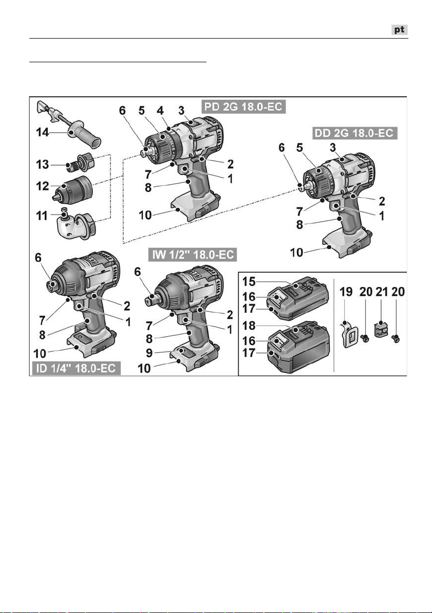
DD 2G 18.0-EC / PD 2G 18.0-EC / IW 1/2" 18.0-EC / ID 1/4" 18.0-EC
Panorâmica da máquina
Neste manual são descritas várias ferramentas eléctricas. As representações gráficas podem
divergir da ferramenta eléctrica adquirida no que diz respeito a detalhes.
1 Interruptor
Para ligar e desligar, assim como para
aumentar a velocidade até ao máximo
de rotações
2 Seletor do sentido de rotação
3 Seletor de velocidade
4 Anel rotativo para o modo de
funcionamento (apenas PD ...)
5 Anel rotativo para a regulação do
binário
6 Admissão da ferramenta
7 Iluminação do posto de trabalho
8 Punho
9 Bedienfeld Drehzahlstufen
10 Módulo recetor para o acumulador
11 Adaptador angular com anel de
desbloqueio
12 Mandril intercambiável com anel
de desbloqueio
13 Adaptador de suporte para bits com
anel de desbloqueio
14 Punho adicional
15 Acumulador de iões de lítio (2,5 Ah)
16 Tecla para desbloquear
o acumulador
17 Indicação do estado do acumulador
18 Acumulador de iões de lítio (5,0 Ah)
19 Grampo para cinto
20 Suporte para bits
21 Parafuso de fixação
79
Page 80

DD 2G 18.0-EC / PD 2G 18.0-EC / IW 1/2" 18.0-EC / ID 1/4" 18.0-EC
Instruções de utilização
Antes da colocação em
funcionamento
Desembalar a ferramenta elétrica
e acessórios e verificar se o fornecimento está completo e se existem danos
provocados pelo transporte.
Fixar o grampo para cinto e o suporte
para bits com o parafuso fornecido.
INDICAÇÃO
Os acumuladores, na altura do fornecimento,
não têm a carga completa. Antes do primeiro
funcionamento, carregar os acumuladores
completamente. Para o efeito, consultar
«Carregador/Operação de carga».
Montar/desmontar o punho
adicional (PD/DD 2G 18.0-EC)
ATENÇÃO!
Utilize punhos adicionais, caso sejam
fornecidos com a ferramenta elétrica. A perda
de controlo pode dar origem a ferimentos.
Mandril intercambiável BF 18.0-EC
ATENÇÃO!
Antes de qualquer intervenção na
ferramenta elétrica, colocar o seletor do
sentido de rotação (2) na posição central.
Montar
Puxar o anel de desbloqueio para
a frente (1.) e pressionar o mandril
intercambiável até ao batente na
admissão da ferramenta (2.).
Soltar o anel de desbloqueio. Controlar
o encaixe do mandril.
Desmontar
Puxar o anel de desbloqueio para a frente
e retirar o mandril.
Aplicação das ferramentas
No mandril, são mantidas seguras brocas
com um diâmetro de 1,5–13 mm, bits de
aparafusamento de ½", bem como
suportes para bits de
Segurar a ferramenta elétrica com uma
mão e rodar o mandril com a outra mão.
– Rodar em sentido contrário ao dos
ponteiros do relógio, para abrir mais
o mandril.
– Rodar no sentido dos ponteiros do
relógio, para fechar o mandril.
½".
80
Aplicar a ferramenta.
Fechar completamente o mandril.
Page 81

DD 2G 18.0-EC / PD 2G 18.0-EC / IW 1/2" 18.0-EC / ID 1/4" 18.0-EC
INDICAÇÃO
Efetuar um teste de funcionamento, para
testar a fixação centrada da ferramenta.
Adaptador angular WV 18.0-EC
ATENÇÃO!
Antes de qualquer intervenção na
ferramenta elétrica, colocar o seletor do
sentido de rotação (2) na posição central.
O adaptador angular facilita o trabalho em
locais de difícil de acesso. O adaptador
angular pode ser encaixado com uma
deslocação de 30º em diferentes posições
angulares.
Montar
Puxar o anel de desbloqueio para a
frente (1.) e pressionar o adaptador
angular até ao encosto na admissão
da ferramenta (2.).
Encaixar o adaptador angular na posição
angular pretendida.
Soltar o anel de desbloqueio. Controlar
o encaixe.
Adaptador de suporte para bits
BV 18.0-EC
ATENÇÃO!
Antes de qualquer intervenção na
ferramenta elétrica, colocar o seletor do
sentido de rotação (2) na posição central.
Montar
Puxar o anel de desbloqueio para
a frente (1.) e pressionar o adaptador
de suporte para bits até ao encosto
na admissão da ferramenta (2.).
Soltar o anel de desbloqueio. Controlar
o encaixe.
Desmontar
Puxar o anel de desbloqueio para
a frente e retirar o adaptador angular.
Aplicação das ferramentas
O adaptador angular possui uma admissão
da ferramenta de
ferramenta, são mantidos seguros bits de
aparafusamento e suportes para bits.
No adaptador angular também se pode
montar o mandril intercambiável (consultar
«Mandril intercambiável BF 18.0-EC») ou
o suporte para bits (consultar «Adaptador
de suporte para bits BV 18.0-EC»).
½". Na admissão da
Desmontar
Puxar o anel de desbloqueio para
a frente e retirar o adaptador de suporte
para bits.
Aplicação das ferramentas
O adaptador de suporte para bits possui
uma admissão da ferramenta de
admissão da ferramenta, são mantidos
seguros bits de aparafusamento.
Puxar o bloqueio de ferramentas para
a frente (1.) e pressionar a ferramenta
até ao batente (2.).
Soltar o bloqueio de ferramentas.
½". Na
81
Page 82
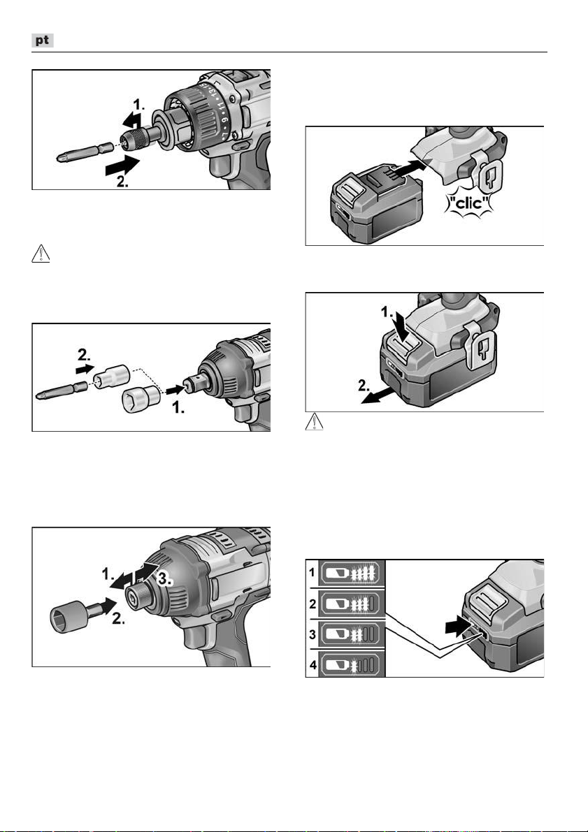
DD 2G 18.0-EC / PD 2G 18.0-EC / IW 1/2" 18.0-EC / ID 1/4" 18.0-EC
Para retirar a ferramenta, puxar
o bloqueio de ferramentas para trás.
Mudança de ferramenta
ATENÇÃO!
Antes de qualquer intervenção na
ferramenta elétrica, colocar o seletor do
sentido de rotação (2) na posição central.
IW 1/2“ 18.0-EC:
Pressionar a chave de caixa sobre
o adaptador quadrangular da
aparafusadora de percussão (1.).
Aplicar a ferramenta na chave de
caixa (2.).
ID 1/4“ 18.0-EC:
Aplicar/substituir o acumulador
Pressionar o acumulador carregado até
encaixar completamente na ferramenta
elétrica.
Para desmontar, pressionar a tecla
de desbloqueio (1.) e retirar o acumulador (2.).
ATENÇÃO!
No caso de não utilização, proteger os
contactos do acumulador. Peças metálicas
soltas podem provocar curto-circuitos nos
contactos, existindo perigo de explosão
e incêndio!
Estado de carga do acumulador
Premindo a tecla, pode verificar-se
o estado de carga no LED de indicação
do estado do acumulador.
Puxar o bloqueio de ferramentas para
a frente (1.) e pressionar a ferramenta
até ao batente (2.).
Soltar o bloqueio de ferramentas.
Para retirar a ferramenta, puxar
o bloqueio de ferramentas para trás (3.).
82
A indicação apaga-se após 5 segundos.
Se um LED piscar, é necessário carregar
o acumulador. Se, depois de se premir
a tecla, nenhum LED se acender, o acumulador está avariado e tem de ser
substituído.
Page 83

DD 2G 18.0-EC / PD 2G 18.0-EC / IW 1/2" 18.0-EC / ID 1/4" 18.0-EC
Pré-seleção do sentido de rotação
ATENÇÃO!
Alterar o sentido de rotação somente com
a ferramenta elétrica completamente parada.
Colocar o seletor do sentido de rotação
na posição necessária:
– À esquerda: contra os ponteiros do
relógio (desenroscar parafusos, soltar
parafusos)
– À direita: no sentido dos ponteiros do
relógio (furar, enroscar parafusos,
apertar parafusos)
– No meio: bloqueio de ligação
(mudança de ferramenta, em todas as
intervenções na ferramenta elétrica)
Modo de funcionamento
(apenas PD 2G 18.0-EC)
ATENÇÃO!
Alterar o modo de funcionamento somente
com a ferramenta elétrica completamente
parada.
Colocar o anel rotativo para o modo de
funcionamento na posição necessária.
Pré-seleção do binário
ATENÇÃO!
Alterar o binário somente com a ferramenta
elétrica completamente parada.
Colocar o anel rotativo para a regulação
do binário na posição necessária.
DD 2G 18.0-EC:
1–23: Aparafusar
: Furar
INDICAÇÃO
Na posição de furar, o acoplamento de
atrito está desativado.
PD 2G 18.0-EC:
Pré-seleção da velocidade
ATENÇÃO!
Alterar a velocidade somente com a ferra-
menta elétrica completamente parada.
: Furar
: Aparafusar
: Perfurar com percussão
Colocar o seletor na fase necessária:
1: Velocidade lenta, binário elevado
2: Velocidade elevada, binário baixo
83
Page 84

DD 2G 18.0-EC / PD 2G 18.0-EC / IW 1/2" 18.0-EC / ID 1/4" 18.0-EC
Ligar a ferramenta elétrica
Ligar o aparelho:
Premir o interruptor.
O interruptor da ferramenta elétrica
permite um aumento gradual do número
de rotações, até ao valor máximo.
Desligar o aparelho:
Soltar o interruptor.
INDICAÇÃO
–
A ferramenta elétrica dispõe de um
travão que para a ferramenta em
utilização imediatamente depois
de se soltar o interruptor.
–
Com uma utilização constante da
ferramenta elétrica, deverá,
principalmente, trabalhar-se com
o interruptor completamente pressionado.
Ligar/desligar a iluminação do
posto de trabalho
1. Comutar o seletor do sentido de
rotação (2) para a posição "Para a
frente" ou "Para trás".
2. Pressionar botão de ligar/desligar (1) da
ferramenta elétrica
– Iluminação do posto de trabalho
acesa
3. Soltar o botão de ligar/desligar (1) da
ferramenta elétrica
– A iluminação do posto de trabalho
apaga-se automaticamente após
aprox. 10 s
Pré-seleção das rotações e do binário
IW 1/2“ 18.0-EC / ID 1/4“ 18.0-EC
Comutar rotações/binário
1. Ativar o botão de ligar/desligar (1)
2. Premir brevemente o interruptor do
modo (aprox. 0,5 s).
– Um LED aceso – binário:
IW 1/2“ 18.0-EC: 150 Nm / 1500 rpm
ID 1/4“ 18.0-EC: 60 Nm / 1500 rpm
3. Premir brevemente o interruptor do modo
– Dois LEDs acesos – binário:
IW 1/2“ 18.0-EC:
ID 1/4“ 18.0-EC:
4. Premir brevemente o interruptor do modo
– Três LEDs acesos – binário:
IW 1/2“ 18.0-EC:
ID 1/4“ 18.0-EC:
5. Premir brevemente o interruptor do modo
– Um LED aceso – binário comuta
de volta para:
IW 1/2“ 18.0-EC: 150 Nm
ID 1/4“ 18.0-EC: 60 Nm
O binário pode ser novamente aumentado
tal como descrito.
Com a ferramenta elétrica em marcha atrás
– apenas uma velocidade de rotação – os
LEDs existentes na base apagam-se
automaticamente.
180 Nm / 2000
105 Nm / 2000 rpm
250 Nm / 2500
225 Nm / 2500 rpm
rpm
rpm
84
Page 85

DD 2G 18.0-EC / PD 2G 18.0-EC / IW 1/2" 18.0-EC / ID 1/4" 18.0-EC
Comutar o modo de impacto para o
modo de aparafusadora de percussão
Pressionar o seletor de modo durante
aprox. 1,5 s.
– Indicador LED do modo aceso – modo
de impacto ativo
– Indicador LED do modo não aceso –
modo de aparafusadora de percussão
ativo.
Trabalhar com a ferramenta elétrica
ATENÇÃO!
Antes de qualquer intervenção na
ferramenta elétrica, colocar o seletor do
sentido de rotação (2) na posição central.
INDICAÇÃO
9. Ligar o aparelho.
Depois de terminado o trabalho:
10. Soltar o interruptor.
11. Colocar o seletor do sentido
de rotação (2) na posição central.
Carregador
Para facilitar o manuseamento ao
aparafusar, o bit de aparafusamento pode
também ser montado diretamente na
admissão da ferramenta do aparelho.
1. Montar a ferramenta (mandril
intercambiável, adaptador angular,
adaptador de suporte para bits).
2. Aplicar o acumulador.
3. Aplicar a ferramenta (broca, bits de
aparafusamento, suporte para bits).
4. Definir o modo de funcionamento
conforme o trabalho a executar
(apenas PD...).
5. Colocar o seletor do binário na fase
necessária.
6. Colocar o seletor da velocidade na fase
necessária.
7. Regular o sentido de rotação necessário.
8. Segurar a ferramenta elétrica com uma
mão no punho e assumir a posição de
trabalho.
Com o motor em funcionamen-to, nunca
acionar o seletor do sentido de rotação
ou a regulação do binário!
1 Módulo recetor para o acumulador
2 Contactos
3 Ranhuras de ventilação
4 Visor de indicação do estado de
funcionamento
5 Cabo de rede com ficha de rede
O carregador CA 10.8/18.0 destina-se ao
carregamento de acumuladores FLEX dos
tipos:
– AP 10.8 (2,5 Ah),
– AP 18.0 (2,5 Ah),
– AP 10.8 (5,0 Ah),
– AP 18.0 (5,0 Ah).
85
Page 86

DD 2G 18.0-EC / PD 2G 18.0-EC / IW 1/2" 18.0-EC / ID 1/4" 18.0-EC
Indicações para uma longa duração
dos acumuladores
ATENÇÃO!
–
Nunca carregar os acumuladores com
temperaturas inferiores a 0 °C ou
superiores a 55 °C.
–
Não carregar os acumuladores num
ambiente com elevada humidade ou
temperatura ambiente.
–
Não tapar os acumuladores, nem o
carregador durante a operação de carga.
–
Desligar a ficha de rede do carregador
depois de terminada a operação de carga.
Durante a operação de carga, o acumulador e
o carregador aquecem. Isso é normal!
Os acumuladores de iões de lítio não apresentam o conhecido efeito «Memory». Apesar
disso, um acumulador, antes de ser carregado, deve estar totalmente descarregado
e a operação de carga tem de ser sempre
totalmente concluída. Se os acumuladores
não forem utilizados por um longo período de
tempo, eles devem ser parcialmente
carregados e guardados em local fresco.
Operação de carga
ATENÇÃO!
Utilizar apenas acumuladores originais
no carregador incluído no fornecimento.
Ligar a ficha de rede do carregador
à tomada.
A luz de fundo do visor acende-se a
verde durante 2 segundos e volta a
apagar-se. É indicado OK.
Inserir o acumulador completamente até
encaixar no carregador.
– No visor, são indicados,
alternadamente, o tempo restante da
operação de carga (até o acumulador
estar totalmente carregado) e uma
representação gráfica do estado de
carga.
– A luz de fundo do visor acende-se
a cor de laranja, se o acumulador
estiver abaixo dos 80% de carga.
– A partir dos 80% de carga do acumu-
lador, o visor acende-se a verde
e é indicado OK.
Quando o acumulador estiver totalmente
carregado, surge a indicação
.
A luz de fundo verde apaga-se após
alguns momentos.
Retirar o acumulador do carregador.
Desligar a ficha da tomada.
INDICAÇÃO
Se, depois da montagem do acumulador,
o visor no carregador piscar, existe uma
falha no acumulador ou no carregador.
Piscar lento do visor.
Luz de fundo cor de laranja.
O acumulador está muito quente ou muito
frio. Depois de ser atingida a temperatura
de carregamento do acumulador
(0°C...55°C), o processo de carga inicia-se.
Piscar rápido do visor.
Luz de fundo vermelha.
Retirar o acumulador do carregador e voltar
a encaixá-lo. Se a indicação se mantiver,
o acumulador está avariado. Substituir
o acumulador ou mandar verificá-lo numa
oficina especializada.
86
Page 87

DD 2G 18.0-EC / PD 2G 18.0-EC / IW 1/2" 18.0-EC / ID 1/4" 18.0-EC
Se surgir a mesma mensagem de falha com
outro acumulador, existe um defeito no
carregador. Mandar verificar o carregador
numa oficina especializada.
Manutenção e tratamento
Limpeza
AVISO!
Ao trabalhar-se com metais e em caso de
utilização extrema, pode depositar-se pó
condutivo no interior da estrutura.
Limpar regularmente a ferramenta elétrica
e as ranhuras de ventilação. A frequência
da limpeza depende do material a trabalhar
e da duração da utilização.
Limpar, regularmente, com ar compri-
mido seco, o interior da estrutura com
motor. Deixar a ferramenta elétrica em
funcionamento.
Carregador
AVISO!
Antes de qualquer intervenção, desligar
a ficha da tomada. Não utilizar água ou
produtos de limpeza líquidos.
Eliminar a sujidade e o pó da estrutura do
aparelho com um pincel ou um pano seco.
Reparações
As reparações devem ser executadas,
exclusivamente, por Serviços Técnicos
autorizados pelo fabricante.
Peças de reparação e acessórios
Para mais acessórios, principalmente ferramentas de aplicação, consulte o catálogo
do fabricante.
Desenhos de explosão e listas de peças de
reparação podem ser consultados na nossa
Homepage: www.flex-tools.com
Transporte
A quantidade equivalente de lítio dos acumuladores incluídos no fornecimento
é inferior aos valores limite em vigor. Por isso,
o acumulador, como peça isolada, e a ferramenta elétrica, com os elementos incluídos
no seu fornecimento, não estão sujeitos a
normas nacionais ou internacionais sobre
materiais perigosos.
No transporte de vários aparelhos com acumuladores de iões de lítio, estas normas
podem tornar-se relevantes e exigir medidas
especiais de segurança (p. ex., para a embalagem). Neste caso, informe-se sobre as
normas em vigor no país de utilização.
Conformidade
Declaramos, sob nossa inteira responsabilidade, que o produto descrito em
«Caraterísticas técnicas» se encontra em
conformidade com as normas e os
documentos normativos seguintes:
EN 62841 de acordo com as determinações das diretivas 2014/30/UE,
2006/42/CE, 2011/65/UE.
Responsável pela documentação técnica:
FLEX-Elektrowerkzeuge GmbH, R & D
Bahnhofstrasse 15, D-71711 Steinheim/Murr
18.12.2017; FLEX-Elektrowerkzeuge GmbH
Bahnhofstrasse 15, D-71711 Steinheim/Murr
Indicações sobre reciclagem
AVISO!
As ferramentas elétricas fora de serviço
devem ser inutilizadas antes de serem
eliminadas:
–
ferramentas elétricas com conexão
à rede por remoção do cabo de rede,
–
ferramentas elétricas com acumulador
por remoção do acumulador.
Só para os países da UE.
Não coloque as ferramentas elétricas
no lixo doméstico! Em conformidade com
a Diretiva Europeia 2012/19/UE sobre
aparelhos elétricos e eletrónicos usados
e com a transposição para o Direito
Nacional, as ferramentas elétricas usadas
têm de ser reunidas separa-damente e
encaminhadas para o reaproveitamento
sem poluição do meio ambiente.
87
Page 88

DD 2G 18.0-EC / PD 2G 18.0-EC / IW 1/2" 18.0-EC / ID 1/4" 18.0-EC
Recuperação de matérias-primas em
vez de eliminação de resíduos.
O aparelho, os acessórios e a embalagem
devem ser encaminhados para reaproveitamento compatível com o meio ambiente.
A identificação dos componentes de plástico
permite a correta separação para reciclagem.
AVISO!
Não deitar acumuladores/baterias no lixo
doméstico, para o fogo ou para a água. Não
abrir acumuladores já inutilizados.
Os acumuladores/baterias devem ser reunidos e reciclados de forma não poluente
para o meio ambiente.
Só para os países da UE.
Em conformidade com a Diretiva Europeia
2006/66/CE, acumuladores/baterias com
defeito ou fora de uso têm de ser reunidas
separadamente e encaminhadas para
o reaproveitamento sem poluição do meio
ambiente.
INDICAÇÃO
Informe-se sobre possibilidades de
reciclagem junto do agente especializado.
Exclusão de responsabilidades
O fabricante e seus representantes não se
responsabilizam por danos e perda de lucros,
resultantes da interrupção do negócio, provocada pelo produto ou pela possível não utilização do mesmo. O fabricante e seus
representantes não se responsabilizam por
danos provocados por uma utilização
inadequada ou em conjugação com produtos
de outros fabricantes.
88
Page 89

DD 2G 18.0-EC / PD 2G 18.0-EC / IW 1/2" 18.0-EC / ID 1/4" 18.0-EC
Inhoud
Gebruikte symbolen . . . . . . . . . . . . . . . 89
Symbolen op het gereedschap . . . . . . . 89
Voor uw veiligheid . . . . . . . . . . . . . . . . . 89
Geluid en trillingen . . . . . . . . . . . . . . . . 91
Technische gegevens . . . . . . . . . . . . . . 92
In één oogopslag . . . . . . . . . . . . . . . . . . 94
Gebruiksaanwijzing . . . . . . . . . . . . . . . . 95
Onderhoud en verzorging . . . . . . . . . . 100
Transport . . . . . . . . . . . . . . . . . . . . . . . 102
-conformiteit . . . . . . . . . . . . . . . . . . 102
Afvoeren van verpakking en machine . 102
Uitsluiting van aansprakelijkheid . . . . . 103
Gebruikte symbolen
WAARSCHUWING!
Geeft een onmiddellijk dreigend gevaar
aan. Als de waarschuwing niet in acht wordt
genomen, dreigen levensgevaarlijke of zeer
ernstige verwondingen.
VOORZICHTIG!
Geeft een mogelijk gevaarlijke situatie aan.
Als de aanwijzing niet in acht wordt
genomen, kan persoonlijk letsel of materiële
schade het gevolg zijn.
LET OP
Geeft gebruikstips en belangrijke informatie
aan.
Symbolen op het gereedschap
Lees de gebruiksaanwijzing
voordat u het gereedschap in
gebruik neemt!
Draag een oogbescherming!
Kortsluitvaste veiligheidstransformator
Bescherm de accu tegen hitte,
bijvoorbeeld door langdurige
inwerking van zonlicht, en vuur.
Er bestaat explosiegevaar.
Werp de accu niet in het vuur.
Er bestaat explosiegevaar.
Apparaat is alleen geschikt voor
gebruik binnen ruimtes. Stel het
apparaat niet bloot aan regen. Sla
elektrische apparaten en accu's
op in droge ruimtes.
Afvalverwijderingsinstructies
(zie pagina 102)!
Voor uw veiligheid
WAARSCHUWING!
Lees alle met het elektrisch gereedschap
meegeleverde veiligheidsvoorschriften,
aanwijzingen, afbeeldingen en specificaties.
Als de veiligheidsvoorschriften en
aanwijzingen niet in acht worden genomen,
kan dit een elektrische schok, brand en/of
ernstig letsel tot gevolg hebben. Bewaar alle
veiligheidsvoorschriften en aanwijzingen voor
de toekomst.
Lees voordat u het elektrische gereedschap
gebruikt en handel daarna volgens:
–
deze gebruiksaanwijzing,
–
de “Algemene veiligheidsvoorschriften”
voor het gebruik van elektrische
gereedschappen in de meegeleverde
brochure (documentnummer: 315.915),
–
de op de plaats van gebruik geldende
regels en voorschriften ter voorkoming
van ongevallen.
Dit elektrische gereedschap is geconstrueerd
volgens de stand van de techniek en de
erkende veiligheidstechnische regels.
Toch kunnen bij het gebruik ervan levensgevaar en verwondingsgevaar voor de
gebruiker en voor andere personen resp.
gevaren voor beschadigingen aan de
machine of aan andere zaken optreden.
89
Page 90

DD 2G 18.0-EC / PD 2G 18.0-EC / IW 1/2" 18.0-EC / ID 1/4" 18.0-EC
Het elektrische gereedschap mag alleen
worden gebruikt
–
volgens de bestemming,
–
in een veiligheidstechnisch optimale
toestand.
Verhelp storingen die de veiligheid in
gevaar brengen onmiddellijk.
Gebruik volgens bestemming
De accu-boorschroevendraaier
DD 2G 18.0-EC is bestemd
– voor professioneel gebruik in de industrie
en door de vakman,
– voor het vastdraaien en losdraaien van
schroeven,
– voor het boren in hout, metaal, keramiek
en kunststof.
De accu-slagschroevendraaier
PD 2G 18.0-EC is bestemd
– voor professioneel gebruik in de industrie
en door de vakman,
– voor het vastdraaien en losdraaien van
schroeven,
– voor het boren in hout, metaal, keramiek
en kunststof,
– voor het slagboren in baksteen,
metselwerk en gesteente.
De accu-slagschroevendraaier
IW 1/2" 18.0-EC / ID 1/4" 18.0-EC is bestemd
– voor professioneel gebruik in de industrie
en door de vakman,
– voor het vastdraaien en losdraaien van
moeren en schroeven in de aangegeven
afmetingen.
Veiligheidsvoorschriften voor
boormachines en
schroevendraaiers
Houd het gereedschap alleen aan de
geïsoleerde greepvlakken vast als
u werkzaamheden uitvoert waarbij
het inzetgereedschap of de schroeven
verborgen stroomleidingen of de eigen
stroomkabel kunnen raken. Contact van
de schroeven met een onder spanning
staande leiding kan ook metalen delen van
het gereedschap onder spanning zetten en
tot een elektrische schok leiden.
Gebruik de extra handgrepen als deze
bij het elektrische gereedschap zijn
geleverd. Het verlies van de controle kan
tot verwondingen leiden.
Gebruik een geschikt detectieapparaat
om verborgen stroom-, gas- of waterleidingen op te sporen of raadpleeg het
plaatselijke energie- of waterleidingbedrijf. Contact met elektrische leidingen
kan tot brand of een elektrische schok
leiden. Beschadiging van een gasleiding
kan tot een explosie leiden. Doordringen in
een waterleiding veroorzaakt materiële
schade.
Schakel het elektrische gereedschap
meteen uit wanneer het inzetgereedschap blokkeert. Wees verdacht op hoge
reactiemomenten, die een terugslag
veroorzaken. Het inzetgereedschap
blokkeert wanneer:
– het elektrische gereedschap wordt
overbelast of
– het in het te bewerken werkstuk verkant.
Houd het elektrische gereedschap
goed vast. Bij het vastdraaien en
losdraaien van schroeven kunnen
gedurende korte tijd hoge
reactiemomenten optreden.
Zet het werkstuk vast. Een met
spanvoorzieningen of een bankschroef
vastgehouden werkstuk wordt beter
vastgehouden dan u met uw hand kunt
doen.
Wacht tot het elektrische gereedschap
tot stilstand is gekomen voordat u het
weglegt. Het inzetgereedschap kan
ergens in verward raken, waardoor u de
controle over het elektrische gereedschap
verliest.
Gebruik alleen originele accu's met de
spanning die op het typeplaatje van uw
elektrisch gereedschap is aangegeven.
Bij gebruik van andere accu's, bijvoorbeeld
imitaties, geregenereerde accu's of
afwijkende fabricaten, bestaat het risico
van verwonding en materiële schade door
exploderende accu's.
Aanvullend veiligheidsvoorschrift
voor slagschroevendraaier (PD ...)
Draag gehoorbescherming bij het
slagboren. De blootstelling aan lawaai kan
gehoorverlies tot gevolg hebben.
90
Page 91

DD 2G 18.0-EC / PD 2G 18.0-EC / IW 1/2" 18.0-EC / ID 1/4" 18.0-EC
Veiligheidsvoorschriften voor de
omgang met accu's
Open de accu niet. Er is risico op
kortsluiting.
Bescherm de accu tegen hitte,
bijvoorbeeld door langdurige inwerking
van zonlicht, en tegen vuur, water en
vocht. Er bestaat explosiegevaar.
Bij beschadiging of onjuist gebruik van de
accu kunnen er dampen vrijkomen. Zorg
voor frisse lucht en raadpleeg bij klachten
een arts. De dampen kunnen de
luchtwegen irriteren.
Bij verkeerd gebruik kan vloeistof uit de
accu lekken. Voorkom contact. Spoel bij
onvoorzien contact met water af. Wanneer
de vloeistof in de ogen komt, dient
u bovendien een arts te raadplegen.
Gelekte accuvloeistof kan tot huidirritaties
en verbrandingen leiden.
Laad accu's alleen op in oplaadapparaten
die door de fabrikant worden geadviseerd.
Voor een oplader die voor een bepaald
type accu geschikt is, bestaat brandgevaar
wanneer deze met andere accu's wordt
gebruikt.
Door spitse voorwerpen zoals spijkers en
schroevendraaiers of door krachtinwerking
van buitenaf kan de accu beschadigd
worden. Er kan een interne kortsluiting
ontstaan en de accu kan ontbranden,
roken, exploderen of oververhit raken.
Oplader
Controleer altijd of de netspanning
overeenkomt met de spanning die op het
typeplaatje van de oplader vermeld is.
De stekker van de oplader moet in het
stopcontact passen. De stekker mag in
geen geval worden veranderd. Gebruik
geen adapterstekkers in combinatie met
geaarde gereedschappen. Onveranderde
stekkers en passende contactdozen
beperken het risico van een elektrische
schok.
Gebruik de oplader uitsluitend in droge
ruimten en vermijd contact met vocht en
regen. Wanneer er water in de oplader
komt, neemt het risico op een elektrische
schok toe.
Gebruik de oplader nooit wanneer de
kabel, de stekker of het apparaat zelf
door invloeden van buitenaf beschadigd
is. Breng de oplader in deze gevallen voor
reparatie naar een vakhandelaar bij u in de
buurt.
Open de oplader in geen enkel geval.
Breng de oplader in geval van storing voor
reparatie naar een vakhandelaar.
Leg geen voorwerpen op de oplader en
plaats de oplader niet op zachte
oppervlakken. Er bestaat brandgevaar.
Speciale veiligheidsvoorschriften
Zet voor alle werkzaamheden aan het
elektrische gereedschap de schakelaar
voor selectie van de draairichting (2) in
de middelste stand.
Bedien de schakelaar voor selectie van
de draairichting (2) en de instelling van
het draaimoment (5) alleen wanneer het
gereedschap stilstaat.
Gebruik voor het markeren van het
elektrische gereedschap alleen stickers.
Boor geen gaatjes in het machinehuis.
Geluid en trillingen
LET OP
De geluids- en trillingswaarden zijn vastgesteld volgens EN 62841. De waarden
kunt u vinden in de tabel “Technische
gegevens”.
WAARSCHUWING!
De aangegeven meetwaarden gelden voor
nieuwe gereedschappen. Bij dagelijks
gebruik veranderen geluids- en
trillingswaarden.
LET OP
Het in deze instructies vermelde trillingsniveau is gemeten volgens een meetmethode zoals beschreven in de norm
EN 62841 en kan worden gebruikt voor
de onderlinge vergelijking van elektrische
gereedschappen. Het is ook geschikt voor
een voorlopige inschatting van de trillingsbelasting. Het vermelde trillingsniveau geldt
voor de voornaamste toepassingen van het
elektrische gereedschap.
91
Page 92

DD 2G 18.0-EC / PD 2G 18.0-EC / IW 1/2" 18.0-EC / ID 1/4" 18.0-EC
Indien het elek-trische gereedschap wordt
gebruikt voor andere toepassingen, met
afwijkende inzetgereedschappen of zonder
voldoende onderhoud, kan het
trillingsniveau afwijken.
Dit kan de trillingsbelasting over het gehele
arbeidstijdvak duidelijk verhogen.
Voor een nauwkeurige schatting van de
trillingsbelasting moeten ook de tijden in
aanmerking worden genomen waarin het
Leg aanvullende veiligheidsmaatregelen vast
ter bescherming van de bediener tegen het
effect van trillingen, zoals: onderhoud van
elektrisch gereedschap en inzetgereedschappen, warm houden van de handen,
organisatie van de arbeidsprocessen.
VOORZICHTIG!
Draag een gehoorbescherming bij een
geluidsdruk van meer dan 85 dB(A).
gereedschap uitgeschakeld is, of waarin het
wel loopt, maar niet feitelijk wordt gebruikt.
Dit kan de trillingsbelasting over het gehele
arbeidstijdvak duidelijk verminderen.
Technische gegevens
Apparaat DD 2G
18.0-EC
Type Boor-
schroe-
vendraaier
Accu AP 18.0/2,5
Oplaadtijd (afhankelijk van
oplaadstatus)
– AP 18.0/2,5
– AP 18.0/5,0
min.
min.
PD 2G
18.0-EC
Slaag-
boor-
schroeven-
draaier
AP 18.0/5,0
0–40
0–45
18.0-EC
IW 1/2"
Slag-
schroe-
vend-
raaier
ID 1/4"
18.0-EC
Slag-
schroe-
vendraaier
Draaimoment, maximaal
– Zachte schroefverbinding
– Harde schroefverbinding
Nm
Nm
56
90
56
90
–
250
Draaikoppelniveaus 20 24 –
Onbelast toerental
– niveau 1
– niveau 2
– niveau 3
Aantal slagen
– niveau 1
– niveau 2
– niveau 3
min.
min.
min.
min.
min.
min.
-1
-1
-1
-1
-1
-1
0...600
0...2300
–
–
–
–
0...600
0...2300
–
0...9600
0...37000
–
1500
2000
2500
1300
2800
3300
Boorhouder mm 1,5–13 –
92
–
225
1500
2000
2500
1300
2800
3300
Page 93

DD 2G 18.0-EC / PD 2G 18.0-EC / IW 1/2" 18.0-EC / ID 1/4" 18.0-EC
Apparaat DD 2G
18.0-EC
Type Boor-
schroe-
vend-
raaier
PD 2G
18.0-EC
Slaag-
boor-
schroeven-
draaier
Max. boordiameter
– in hout
– in staal
– in metselwerk
Gewicht volgens “EPTA-procedure
01/2003” (zonder accu)
Gewicht accu 2,5 Ah
5,0 Ah
mm
mm
mm
60
13
16
60
13
16
kg 1,5 1,6 1,1 1,1
kg
kg
A-gewogen geluidsdrukniveau
Geluidsdrukniveau L
pA
Geluidsvermogenniveau L
WA
dB(A) 78* 78* / 95** 91*** 91***
dB(A) 89* 89* / 106** 102*** 102***
Onzekerheid K db 3,0
Totale trillingswaarden (vectortotaal uit drie richtingen)
Trillingsemissiewaarde a
– Boren in metaal
– Slagboren in beton
– Schroeven
Onzekerheid K
* Boren in metaal / ** Slagboren in beton / *** Slagschroeven
bij ....
h
m/s
m/s
m/s
m/s
2
2
2
2
<2,5 <2,5 – –
– 15,5 – –
<2,5 <2,5 18,5*** 18,5***
0,4
0,7
1,5
IW 1/2"
18.0-EC
Slag-
schroe-
vendraaier
–
–
–
ID 1/4"
18.0-EC
Slag-
schroe-
vendraaier
–
–
–
93
Page 94

DD 2G 18.0-EC / PD 2G 18.0-EC / IW 1/2" 18.0-EC / ID 1/4" 18.0-EC
In één oogopslag
In deze gebruiksaanwijzing worden verschillende elektrische gereedschappen beschreven.
Details van de afbeeldingen kunnen afwijken van het door u gekochte elektrische gereedschap.
1 Schakelaar
Voor het in- en uitschakelen en het op
toeren komen tot het maximale
toerental
2 Schakelaar voor selectie draairichting
3 Schakelaar voor snelheidsselectie
4 Drehring für Betriebsart (alleen PD ...)
5 Draairing voor instelling draaimoment
6 Gereedschapsopname
7 Werkplekverlichting
8 Handgreep
9 Bedieningsveld toerentalstanden
10 Insteeksleuf voor accu
94
11 Hoekvoorzetstuk met
ontgrendelingsring
12 Wisselboorhouder met
ontgrendelingsring
13 Bithoudervoorzetstuk met
ontgrendelingsring
14 Extra handgreep
15 Li-ion-accu (2,5 Ah)
16 Ontgrendelknop voor accu
17 Statusindicatie accu
18 Li-ion-accu (5,0 Ah)
19 Riemklem
20 Bevestigingsschroef
21 Bithouder
Page 95
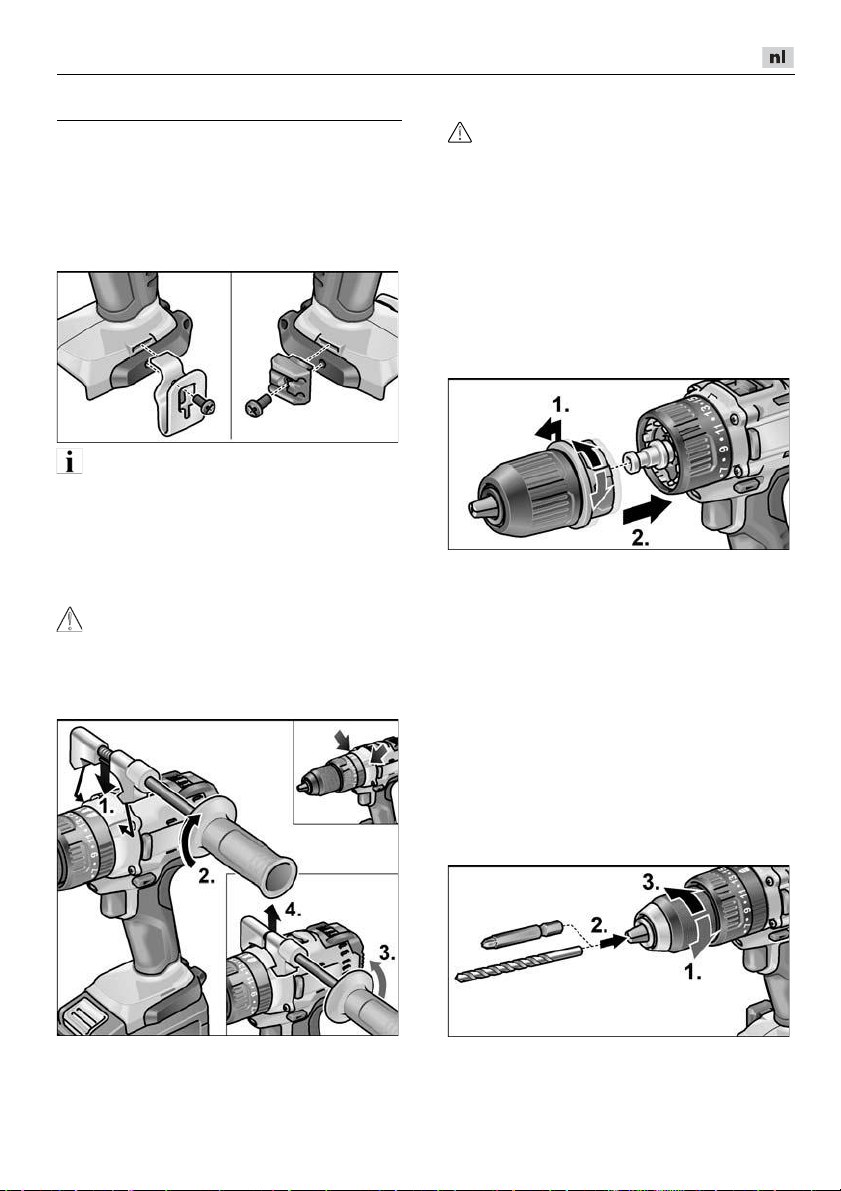
DD 2G 18.0-EC / PD 2G 18.0-EC / IW 1/2" 18.0-EC / ID 1/4" 18.0-EC
Gebruiksaanwijzing
Voor de ingebruikneming
Pak het elektrische gereedschap uit en
controleer of het volledig geleverd is en
geen transportschade heeft.
Bevestig de riemklem of bithouder met
de meegeleverde schroef.
LET OP
De accu's zijn bij levering niet volledig
opgeladen. Laad de accu's volledig op voor
het eerste gebruik. Zie ook “Oplader/
Oplaadproces”.
Extra handgreep monteren/
demonteren (PD/DD 2G 18.0-EC)
VOORZICHTIG!
Gebruik de extra handgrepen als deze bij
het elektrische gereedschap zijn geleverd.
Het verlies van de controle kan tot
verwondingen leiden.
Wisselboorhouder BF 18.0-EC
VOORZICHTIG!
Zet voor alle werkzaamheden aan het
elektrische gereedschap de schakelaar
voor selectie van de draairichting (2) in de
middelste stand.
Monteren
Ontgrendelingsring naar voren trekken (1.)
en wisselboorhouder tot aan de aanslag op
de gereedschapsopname drukken (2.).
Ontgrendelingsring loslaten.
Vastklikmechanisme van de boorhouder
controleren.
Demonteren
Ontgrendelingsring naar voren trekken
en boorhouder afnemen.
Inzetten van het gereedschap
In de boorhouder worden boren met een
diameter van 1,5–13 mm, schroevendraaierbits
vastgehouden.
Houd het elektrische gereedschap met
één hand vast en draai de boorhouder
met de andere hand.
– Draai tegen de klok in om de boorhouder
– Draai met de klok mee om de
½" en bithouders ½" veilig
verder te openen.
boorhouder te sluiten.
Plaats het gereedschap.
Sluit de boorhouder geheel.
95
Page 96

DD 2G 18.0-EC / PD 2G 18.0-EC / IW 1/2" 18.0-EC / ID 1/4" 18.0-EC
LET OP
Laat het inzetgereedschap proefdraaien om
te controleren of het gecentreerd
ingespannen is.
Hoekopzetstuk WV 18.0-EC
VOORZICHTIG!
Zet voor alle werkzaamheden aan het
elektrische gereedschap de schakelaar
voor selectie van de draairichting (2) in de
middelste stand.
Het hoekopzetstuk vergemakkelijkt het
werken op moeilijk toegankelijke plaatsen.
Het hoekopzetstuk kan in diverse
hoekstanden van telkens 30° verplaatst
vastklikken.
Monteren
Ontgrendelingsring naar voren trekken (1.)
en hoekopzetstuk tot aan de aanslag op de
gereedschapsopname drukken (2.).
Hoekopzetstuk in de gewenste
hoekstand laten vastklikken.
Ontgrendelingsring loslaten.
Vastklikmechanisme controleren.
Bithouderopzetstuk BV 18.0-EC
VOORZICHTIG!!
Zet voor alle werkzaamheden aan het
elektrische gereedschap de schakelaar
voor selectie van de draairichting (2) in de
middelste stand.
Monteren
Ontgrendelingsring naar voren trekken (1.)
en bithouderopzetstuk tot aan de aanslag
op de gereedschapsopname drukken (2.).
Ontgrendelingsring loslaten.
Vastklikmechanisme controleren.
Demonteren
Ontgrendelingsring naar voren trekken
en hoekopzetstuk afnemen.
Inzetten van het gereedschap
Het hoekopzetstuk beschikt over een ½"
gereedschapsopname. In de gereedschapsopname worden schroevendraaierbits en bithouders veilig vastgehouden.
Op het hoekopzetstuk kan ook de
wisselboorhouder (zie “Wisselboorhouder
BF 18.0-EC”) of de bithouder (zie
“Bithouderopzetstuk BV 18.0-EC”)
gemonteerd worden.
96
Demonteren
Ontgrendelingsring naar voren trekken
en bithouderopzetstuk afnemen.
Inzetten van het gereedschap
Het bithouderopzetstuk beschikt over een
½" gereedschapsopname. In de gereed-
schapsopname worden schroevendraaierbits veilig vastgehouden.
Gereedschapsvergrendeling naar voren
trekken (1.) en het gereedschap tot aan
de aanslag indrukken (2.).
Laat de gereedschapsvergrendeling los.
Page 97

DD 2G 18.0-EC / PD 2G 18.0-EC / IW 1/2" 18.0-EC / ID 1/4" 18.0-EC
Accu plaatsen/vervangen
Druk de geladen accu in het elektrische
gereedschap totdat deze vergrendelt.
Trek de gereedschapsvergrendeling
naar achteren om het gereedschap te
verwijderen.
Gereedschapswisseling
VOORZICHTIG!
Zet voor alle werkzaamheden aan het
elektrische gereedschap de schakelaar
voor selectie van de draairichting (2) in de
middelste stand.
IW 1/2“ 18.0-EC:
Steeksleutel op vierkant voorzetstuk van
de slagschroevendraaier drukken (1.).
Gereedschap in steeksleutel plaatsen (2.).
ID 1/4“ 18.0-EC:
Om de accu te verwijderen, drukt u op de
ontgrendelknop (1.) en trekt u de accu
eruit (2.).
VOORZICHTIG!
Bescherm de contacten van de accu
wanneer deze niet wordt gebruikt. Losse
metalen onderdelen kunnen de contacten
kortsluiten; er is explosie- en brandgevaar!
Oplaadstatus van de accu
De oplaadstatus van de accu is te
controleren met de LED van de
accustatus-indicator.
Gereedschapsvergrendeling naar voren
trekken (1.) en het gereedschap tot aan
de aanslag indrukken (2.).
Laat de gereedschapsvergrendeling los.
Trek de gereedschapsvergrendeling
naar achteren om het gereedschap te
verwijderen (3.).
De indicator gaat na 5 seconden uit.
Als de LED knippert, moet de accu worden
opgeladen. Als de LED na het indrukken
van de knop niet oplicht, is de accu defect
en moet deze worden vervangen.
97
Page 98

DD 2G 18.0-EC / PD 2G 18.0-EC / IW 1/2" 18.0-EC / ID 1/4" 18.0-EC
Selectie van de draairichting
VOORZICHTIG!
Wijzig de draairichting alleen als het
elektrische gereedschap stilstaat.
Zet de selectieschakelaar voor de
draairichting in de gewenste stand:
– Links: tegen de klok in (schroeven
uitdraaien, schroeven losdraaien)
– Rechts: met de klok mee
(boren, schroeven indraaien, schroeven
vastdraaien)
– Midden: inschakelblokkering
(gereedschapswissel, bij alle
werkzaamheden aan het elektrische
gereedschap)
Bedrijfsmodus
(alleen PD 2G 18.0-EC)
VOORZICHTIG!
Wijzig de bedrijfsmodus alleen als het
elektrische gereedschap stilstaat.
Draai de draairing voor de bedrijfsmodus
in de gewenste positie.
Selectie van het draaimoment
VOORZICHTIG!
Wijzig het draaimoment alleen als het
elektrische gereedschap stilstaat.
Draai de draairing voor het instellen van
het draaimoment in de gewenste positie.
DD 2G 18.0-EC:
1–23: Schroeven
: Boren
LET OP
In de boorstand is de slipkoppeling
gedeactiveerd.
PD 2G 18.0-EC:
Snelheidsselectie
VOORZICHTIG!
Wijzig de snelheid alleen als het elektrische
gereedschap stilstaat.
: Boren
: Schroeven
: Slagboren
98
Keuzeschakelaar op gewenst niveau
instellen:
1: lage snelheid, hoog draaimoment
2: hoge snelheid, laag draaimoment
Page 99

DD 2G 18.0-EC / PD 2G 18.0-EC / IW 1/2" 18.0-EC / ID 1/4" 18.0-EC
Elektrisch gereedschap inschakelen
Apparaat inschakelen:
Druk de schakelaar in.
Met de schakelaar van het elektrische
gereedschap kan het toerental
stapsgewijs tot de maximale waarde
worden verhoogd.
Apparaat uitschakelen:
Laat de schakelaar los.
LET OP
–
Het elektrische gereedschap beschikt
over een rem, waardoor het inzetgereedschap na het loslaten van de
schakelaar meteen stopt.
–
Wanneer het elektrische gereedschap
langdurig wordt gebruikt, moet er
hoofdzakelijk met een volledig ingedrukte
schakelaar worden gewerkt.
Werkplekverlichting in-/
uitschakelen
1. Keuzeschakelaar voor draairichting (2)
in stand „vooruit“ of „achteruit“ zetten.
2. Aan-/uit-schakelaar (1) elektrisch
gereedschap indrukken
– Werkplekverlichting brandt
3. Aan-/uit-schakelaar (1) elektrisch
gereedschap loslaten
– Werkplekverlichting dooft automatisch
na ca. 10 s
Toerental- en draaimomentkeuze
IW 1/2“ 18.0-EC / ID 1/4“ 18.0-EC
Toerental/draaimoment omschakelen
1. Aan-/uit-schakelaar (1) inschakelen
2. Modusschakelaar kort indrukken
(ca. 0,5 s).
– Eén LED brandt – draaimoment:
IW 1/2“ 18.0-EC:
ID 1/4“ 18.0-EC:
3. Modusschakelaar kort indrukken
– Twee LED's branden – draaimoment:
IW 1/2“ 18.0-EC:
ID 1/4“ 18.0-EC:
4. Modusschakelaar kort indrukken
– Drie LED's branden – draaimoment:
IW 1/2“ 18.0-EC:
ID 1/4“ 18.0-EC:
5. Modusschakelaar kort indrukken
– Eén LED brandt – draaimoment
schakelt terug naar:
IW 1/2“ 18.0-EC: 150 Nm
ID 1/4“ 18.0-EC: 60 Nm
Draaimoment kan zoals beschreven weer
opgevoerd worden.
In de achteruitloop van het elektrische
gereedschap – heeft slechts één toerental –
gaan de LED's in de voet automatisch uit.
150 Nm / 1500 min
60 Nm / 1500 min
180 Nm / 2000 min
105 Nm / 2000 min
250 Nm / 2500 min
225 Nm / 2500 min
-1
-1
-1
-1
-1
-1
Enkeleslagmodus in slagschroevendraaiermodus omschakelen
Modusschakelaar ca. 1,5 s indrukken.
– LED-modusindicatie brandt –
enkeleslagmodus actief.
– LED-modusindicatie brandt niet –
slagschroevendraaiermodus actief.
Werkzaamheden met het elektrische gereedschap
VOORZICHTIG!
Zet voor alle werkzaamheden aan het
elektrische gereedschap de schakelaar
voor selectie van de draairichting (2) in
de middelste stand.
99
Page 100

DD 2G 18.0-EC / PD 2G 18.0-EC / IW 1/2" 18.0-EC / ID 1/4" 18.0-EC
LET OP
Om ervoor te zorgen dat de bediening bij het
schroeven gemakkelijker gaat, kan de
schroefbit ook direct in de gereedschapsopname van het apparaat ingezet worden.
1. Gereedschapshouder (wisselboor-
houder, hoekopzetstuk) monteren.
2. Plaats de accu.
3. Gereedschap (boren, schroefbits,
bithouder) inzetten.
4. Bedrijfsmodus aan de hand van de taak
instellen (alleen PD...).
5. Stel de selectie van het draaimoment
in op het gewenste niveau.
6. Stel de snelheid in op het gewenste
niveau.
7. Stel de gewenste draairichting in.
8. Houd het elektrische gereedschap met
één hand vast aan de handgreep en
neem de werkpositie in. Bedien bij
draaiende motor nooit de schakelaar
voor selectie van de draairichting of de
instelling van het draaimoment!
9. Schakel het apparaat in.
Na einde van de werkzaamheden:
10. Laat de schakelaar los.
11. Zet de schakelaar voor selectie van de
draairichting (2) in de middelste stand.
Oplader
1 Insteeksleuf voor accu
2 Contacten
3 Ventilatiespleten
4 Display voor weergave van de
bedrijfsmodus
5 Stroomkabel met stekker
De oplader CA 10.8/18.0 is bestemd voor
het opladen van FLEX-accu's van de typen
– AP 10.8 (2,5 Ah),
– AP 18.0 (2,5 Ah),
– AP 10.8 (5,0 Ah),
– AP 18.0 (5,0 Ah).
Aanwijzingen voor een lange acculevensduur
VOORZICHTIG!
–
Laad accu's nooit op bij temperaturen
lager dan 0 °C of hoger dan 55 °C.
–
Laad accu's niet op in een omgeving met
hoge luchtvochtigheid of hoge
omgevingstemperatuur.
–
Bedek de accu's en oplader niet tijdens
het laden.
–
Trek de stekker van de oplader na het
opladen uit het stopcontact.
Tijdens het opladen worden de accu en de
oplader warm. Dat is normaal!
Lithium-ion-accu's hebben niet het bekende
“memory-effect”. Toch moet een accu voor
het opladen volledig worden ontladen en
moet het laadproces altijd volledig worden
afgesloten.
Bewaar de accu's gedeeltelijk geladen op
een koele plek wanneer de accu's langere
tijd niet worden gebruikt.
100
 Loading...