

FLETCHER 2200 Owner's Manual
OWNER’S
MANUAL
FLETCHER 2200™
PROFESSIONAL MAT CUTTER
German Page 19
French Page 37
Spanish Page 55
The Fletcher-Terry Company
65 Spring Lane • Farmington, CT 06032-3311
Tel 860.677.7331• 800.843.3826 • Fax 860.676.8858 • www.fletcher-terry.com
customerservice@fletcher-terry.com
1
FORM 122003
Ver. 3.16.4

TABLE OF CONTENTS
INTRODUCTION 3
WARRANTY 3
COMPONENTS 4
SET UP 5
HOW TO CUT MATS 6
SINGLE OPENING 6
V-GROOVE 7
DOUBLE MAT 7
MULTI-ANGLE MAT 11
OPTIONS 8
MEASURING STOPS 8
MAT CLAMP LIFTERS 8
RIGHT SQUARING ARM 9
BASE EXTENSION 10
ANGLE MAT GUIDE 11
ADJUSTMENTS 12
SQUARE MAT GUIDE 12
ADJUST CUTTING HEAD 12
MAINTENANCE 13
TROUBLESHOOTING GUIDE 14
PARTS LISTS 15
GERMAN 19
FRENCH 37
SPANISH 55
2

INTRODUCTION
The Fletcher 2200™ Professional Mat Cutter is designed with the professional framer in mind and has evolved from the
proven concepts of the Fletcher 2000® and Fletcher 2100® and incorporates many suggestions from the users of
Fletcher-Terry framing products. Particular attention has been devoted to ergonomic design to provide comfort and ease
of use. The Fletcher 2200 is available in imperial (40”, 48” and 60”) and metric (1.0m, 1.2m and 1.5m) versions.
The Cutting Head incorporates both bevel and straight cutting with comfort designed into both pivots. The straight
(sizing) side uses a blade and magazine that cuts materials such as foamboard and gatorfoam® up to a nominal 1/2”
(12mm) thick. Both magazines permit blade changing away from the Cutting Head minimizing exposure to the hazard of
handling sharp blades. A unique Sight Gage on the Cutting Head provides precise control of over/under cuts when
using pencil lines on the back of the mat.
The Cutting Head is fitted to a polished Shaft minimizing wear and “hooking”. Adjustments are available so the framer
can maintain the close fit in spite of heavy usage.
The usefulness of the popular Locator Pin has been improved by adding holes in the Mat Guide Slide to provide mat
borders from 1-1/2” to 8” in 1/2” increments on the imperial version and 30mm to 210mm in 10mm increments on the
metric version.
Options include: Measuring Stops assure minimum over cuts and under cuts; Clamp Lifters allow both hands to be free
to place the mat in position; the Right Squaring Arm attaches to the base providing a rigid, accurate means of sizing
mats; the Angle Mat Guide attaches to the Mat Guide creating a means of cutting angles other than 90 degrees in an
opening and a Base Plate Extension permits mat borders up to 16” (405mm).
Multiple mats, V-grooves, and other creative mat designs can be easily and accurately produced on the Fletcher 2200.
Product Warranty
The Fletcher-Terry Company warrants the Fletcher 2200 to be free from defects in parts and
workmanship for (2) two years from the date of purchase. The Fletcher-Terry Company warrants
that it will repair or replace any such defective machine or replace parts, providing the machine
has been under normal use and service and the defective part or machine is returned to The
Fletcher-Terry Company at the purchaser’s expense. The Fletcher-Terry Company must authorize the return in writing. Proof of purchase must be submitted to validate warranty coverage.
The warranty is in lieu of all other agreements and warranties expressed or implied. THE
FLETCHER-TERRY COMPANY DOES HEREBY EXPRESSLY DISCLAIM ANY WARRANTIES
OF MERCHANTABILITY OR FITNESS FOR A PARTICULAR PURPOSE. The Fletcher-Terry
Company does not authorize any company employee or representative to assume for it any
other liability than that set forth in this Product Warranty. The Fletcher-Terry Company shall not
be liable for any damages or losses, whether incidental or consequential or direct or indirect,
arising out of the use or abuse of this machine. In any event, THE PURCHASER’S SOLE AND
EXCLUSIVE REMEDY UNDER THIS OR ANY OTHER WARRANTY IS LIMITED TO RETURN
OF THE PURCHASE PRICE PAID FOR THIS MACHINE.
3
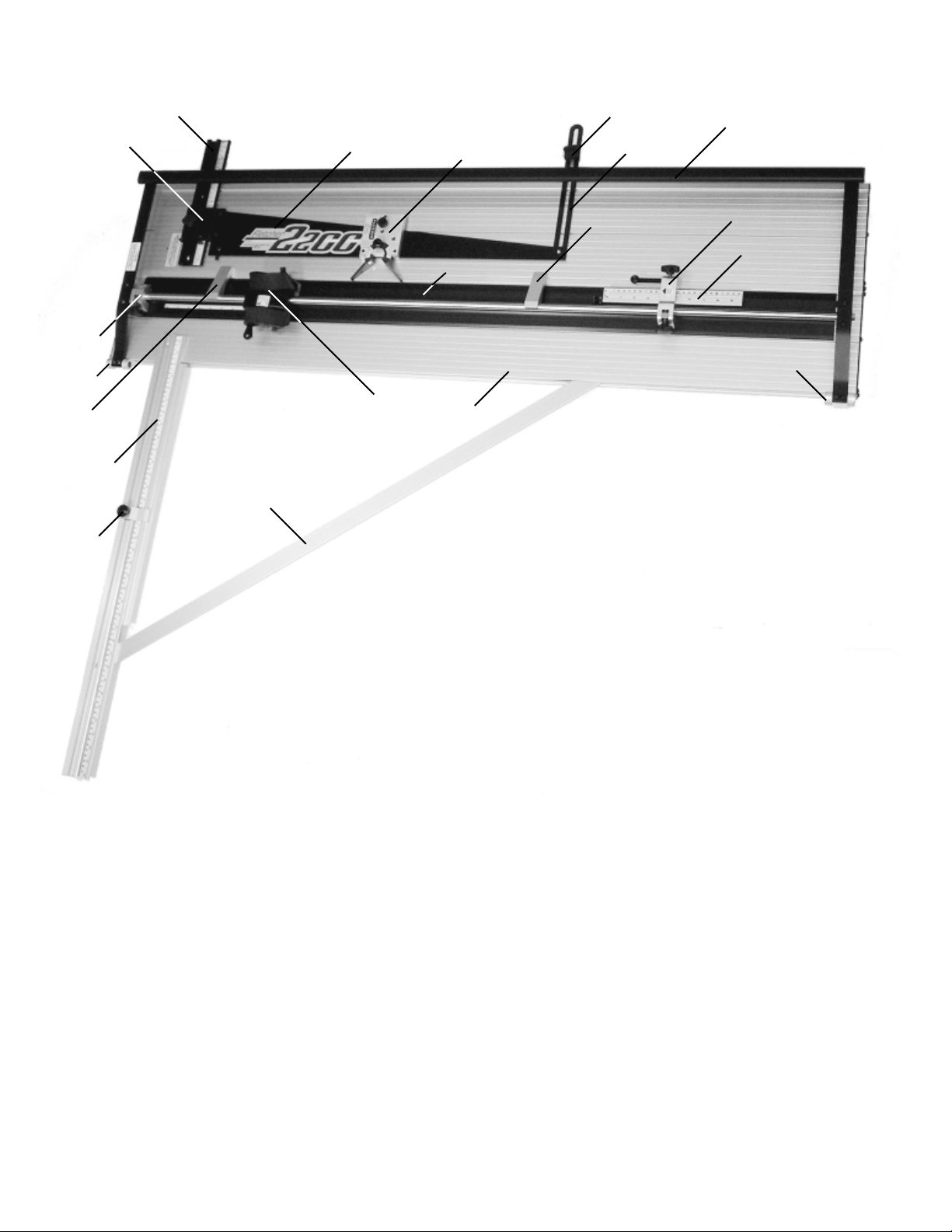
COMPONENTS
17
15
12
9
14
78
6
16
2
4
1 Base
2 Mat Guide
3 Clamp
4 Cutting Head
5 Clamp Handle
6 Lower Mat Guide Locking Knob
7 Upper Mat Guide Locking Knob
8 Mat Guide Slide
9 Hinge Pivot
10 Strap
11 Upper Measuring Stop
12 Lower Measuring Stop
13 Upper Stop Scale
14 Right Squaring Arm
15 Right Squaring Arm Stop
16 Right Squaring Arm Brace
17 Squaring Fixture
18 Angle Mat Guide
18
3
1
10
17
5
11
13
9
4

SET UP
Place nine self adhesive rubber bumpers from the parts bag equally spaced on the bottom of the Base to prevent
scratching a table top. Set the Fletcher 2200 on a flat table with the Clamp Handle to the left.
CAUTION:
USE EXTREME CARE
HANDLING BLADES.
THEY ARE VERY SHARP
MAT BLADES
The bevel cutting side of the Cutting Head accepts any of three different Fletcher Mat Blades. The 05-012 is .012”
(.3mm) thick and is used for cutting regular mats. The 05-015 is .015” (.4mm) thick and is used for denser or thicker
mats. The 05-016 is a single edge blade, beveled on one side only. It is used for very dense or thick mats and must be
installed with the beveled edge away from the head.
The straight sizing blade on the right is the Utility Blade, 05-004, and is capable of cutting material up to a nominal
1/2” (12mm) thick. All blades except the 05-016 single edge blade can be reversed in their magazine to double the life of
the blade, however, they must be inserted carefully
to avoid damage.
1. Insert a Blade (C) in the bevel cutting Magazine
(A) as shown in Figure 1. The Blade Extension
Screw (B) should be adjusted so the Blade (C)
penetrates about 1/3rd the thickness of a slip
sheet under the mat being cut. The blade should
always rest against the Blade Extension Screw
(B), and the Magazine (A) must be fully inserted
in the Cutting Head (D). Tighten its Locking
Knob (E) firmly. See Figure 3.
C
F
A
Figure 1
B
J
2. Straight cutting (sizing) is done on the right side
of the Cutting Head (D). The Magazine (F) and
Utility Blade (G), (05-004), are shown in Figure 2.
There are 4 possible depth positions for this blade,
but only two are used as seen in Figures 2 and 2a.
Figure 2a is the position for nominal 1/2” (12mm)
material, while Figure 2 is for 2, 4, 6, and 8 ply mat
board. The blade is held in place by a magnet. Insert
the Magazine (F) to a stop in the Cutting Head (D)
and tighten its Locking Knob (K). See Figure 4.
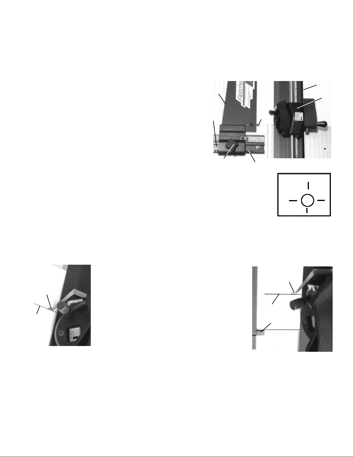
3. The Sight Gage (L) shown in Figure 3 is used to control the start of cut and end of cut when using pencil lines drawn
on the back of the mat. It is held in place on the Cutting Head with a magnet and can
D
D
E
L
Figure 3
Figure 4
be removed and set aside when not being used. The
use of this feature is explained on the following page.
K
Figure 2
Figure 2a
F
H
G
D
5
HOW TO CUT MATS
SINGLE OPENING
The most important requirement for cutting a good mat is a sharp blade. Mats are abrasive and will wear out a blade
eventually. The value of a well cut mat is far greater than the cost of a blade.
1. Prepare a slip sheet about 8” (200mm) wide and 40” (1016mm) long
and place it under the Mat Clamp (A). Use a piece of mat the same
thickness as the one you will be cutting and lay it on top of the slip
sheet. Press down on the Handle lightly to hold the mat in place.
Slide the Cutting Head (B) beyond the edge of the mat and rotate
the Pivot to insert the blade in the slip sheet. You can now observe
the tip of the blade which should penetrate about 1/3 the thickness of
the slip sheet. Mats of a different thickness will require retesting and
adjustment of the blade extension. If you press down on the Handle
with too much force, the Mat Clamp will bow upward in the center.
This increases the distance between the blade tip and the mat at the
center of the cut and may prevent full penetration of the blade when
cutting a large mat. Use only enough downward pressure to lock the
mat in place so it does not move. See Figure 5.
2. The Locator Pin (C) provides accurate and repeatable settings for mat borders from 1-1/2” to
8“ in increments of 1/2” for the imperial measurement version. The Mat Gage adds 1/8”, 3/16”,
1/4” or 5/16” to the Locator Pin positions. The metric version has Locator Pin holes for mat
borders from 30mm to 210mm in increments of 10mm. The metric Mat Gage adds 3mm, 4mm,
5mm, or 7mm to the Locator Pin setting. The ability to repeat settings accurately is an advantage over reading a scale, especially when producing multiple mats.
3. For example, cut a single mat with a 3” (70mm) border and a V-groove at 2-1/2” (60mm). Insert the Locator Pin in
the third hole from the right in the Mat Guide Slide (D) and slide the Mat Guide (F) to the right to contact the Loca-
tor Pin. Tighten both the Lower Mat Guide Locking Knob (E) and the Upper Mat Guide Locking Knob shown as
no. 7 on page 4. Always tighten them in this sequence, lower before upper. Place a pre-sized 16” X 20” (400mm X
500mm) matboard upside down and slide it to the left against the Mat Guide and downward against the Mat Stop
(G). Lower the Clamp Handle. Use a sharp pencil
(never ink) and draw a line along the left edge of the
Clamp starting and stopping about 1/2” (13mm) from
H
K
the edges of the mat. Rotate the mat 90 degrees and repeat drawing the pencil line until all four side have been
penciled. Also pencil the mat where the border will join
the “fall-out” at one side so you can maintain the same
orientation later during V-grooving or cutting Double
Mats.
F
D
E
C
G
Figure 5
4
5
16
H
L
G
A
1
1
8
B
16
3
4. Press down on the Clamp Handle and pivot the bevel
cutting blade into the mat for the start of a cut. Figure 6
FFigure 6
5. Make the cut, stopping when the Sight Gage (H) reaches the lower pencil line (L). This is the end of cut and is shown
in Figure 7.
6. Raise the Handle, rotate the mat 90 degrees and repeat the next cut, starting and stopping at the cross pencil
lines as before. Remove the mat and examine the top side. There should be a barely perceptable overcut at each
corner to assure the “fall-out” is cut free of the mat. Excessive overcuts or undercuts should be corrected by your
judgement in lining up the Sight Gage with the pencil lines as well as the blade extension.
shows the starting position by lining up the Sight Gage
(H) with the upper pencil line (K).
Figure 7
6
AAAA
 Loading...