

FLENDER H Series, M Series, B Series, H2SH 24, SOND 622 Operating Instructions Manual
...
FLENDER Gear Units
Gear unit
Operating Instructions 5118en
Edition 10/2017
H..., B..., M..., SOND

18.09.2017 15:44
V7.02

FLENDER Gear Units
Gear unit
5118en
H..., B..., M..., SOND
Introduction
1
Operating Instructions
Safety instructions
Description
Application planning
Assembly
Commissioning
Operation
Servicing
2
3
4
5
6
7
8
Service & Support
Disposal
Spare parts
Quality documents
Technical data
9
10
11
A
B
Edition 10/2017
Legal information
Warning notice system
This manual contains notices you have to observe in order to ensure your personal safety, as well as to prevent
damage to property. The notices referring to your personal safety are highlighted in the manual by a safety alert
symbol, notices referring only to property damage have no safety alert symbol. These notices shown below are
graded according to the degree of danger.
DANGER
indicates that death or severe personal injury will result if proper precautions are not taken.
WARNING
indicates that death or severe personal injury may result if proper precautions are not taken.
CAUTION
indicates that minor personal injury can result if proper precautions are not taken.
NOTICE
indicates that property damage can result if proper precautions are not taken.
If more than one degree of danger is present, the warning notice representing the highest degree of danger will be
used. A notice warning of injury to persons with a safety alert symbol may also include a warning relating to property
damage.
Qualified Personnel
The product/system described in this documentation may be operated only by personnel qualified for the specific
task in accordance with the relevant documentation, in particular its warning notices and safety instructions. Qualified
personnel are those who, based on their training and experience, are capable of identifying risks and avoiding
potential hazards when working with these products/systems.
Proper use of Flender products
Note the following:
WARNING
Flender products may only be used for the applications described in the catalog and in the relevant technical
documentation. If products and components from other manufacturers are used, these must be recommended or
approved by Flender. Proper transport, storage, installation, assembly, commissioning, operation and maintenance
are required to ensure that the products operate safely and without any problems. The permissible ambient
conditions must be complied with. The information in the relevant documentation must be observed.
Trademarks
All names identified by ® are registered trademarks of Flender GmbH. The remaining trademarks in this publication
may be trademarks whose use by third parties for their own purposes could violate the rights of the owner.
Disclaimer of Liability
We have reviewed the contents of this publication to ensure consistency with the hardware and software described.
Since variance cannot be precluded entirely, we cannot guarantee full consistency. However, the information in
this publication is reviewed regularly and any necessary corrections are included in subsequent editions.
Flender GmbH
Alfred-Flender-Straße 77
46395 BOCHOLT
GERMANY
Document order number: 5118en
Ⓟ 09/2017 Subject to change
Copyright © Flender GmbH 2017.
All rights reserved

Table of contents
1 Introduction.................................................................................................................................................11
1.1 General information................................................................................................................11
1.2 Lubricants...............................................................................................................................12
2 Safety instructions......................................................................................................................................13
2.1 Security notes........................................................................................................................13
2.2 The five safety rules...............................................................................................................13
2.3 General information................................................................................................................14
2.4 General warnings and symbols..............................................................................................15
2.5 Special types of danger and personal protective equipment.................................................16
2.6 Intended use..........................................................................................................................18
3 Description..................................................................................................................................................21
3.1 General description................................................................................................................21
3.2 Output shaft versions.............................................................................................................21
3.3 Housing..................................................................................................................................21
3.4 Oil supply to the gear unit......................................................................................................24
3.4.1 Splash lubrication...................................................................................................................25
3.4.2 Pressure lubrication...............................................................................................................25
3.5 Bearing arrangement of the shafts.........................................................................................25
3.6 Shaft seal...............................................................................................................................26
3.6.1 Rotary shaft sealing rings.......................................................................................................26
3.6.2 Labyrinth seals.......................................................................................................................26
3.6.3 Taconite seal..........................................................................................................................27
3.6.4 Tacolab seal...........................................................................................................................28
3.7 Cooling...................................................................................................................................30
3.7.1 Fan.........................................................................................................................................30
3.7.2 Cooling coil.............................................................................................................................31
3.7.3 Mounted oil supply system.....................................................................................................33
3.7.3.1 Pump......................................................................................................................................33
3.7.3.2 Oil filter...................................................................................................................................34
3.7.3.3 Pressure monitor....................................................................................................................34
3.7.4 Separate oil supply system....................................................................................................34
3.8 Couplings...............................................................................................................................34
3.9 Heating...................................................................................................................................35
3.10 Oil level indicator....................................................................................................................36
3.11 Oil-level monitoring system....................................................................................................37
Gear unit 5118en
Operating Instructions 10/2017 5

Table of contents
3.12 Oil temperature monitoring.....................................................................................................38
3.13 Bearing monitoring.................................................................................................................38
3.13.1 Bearing monitoring using a Pt 100 resistance thermometer..................................................38
3.13.2 Bearing monitoring by shock-pulse transducer......................................................................39
3.13.3 Bearing monitoring by acceleration sensor............................................................................40
3.14 Speed encoder.......................................................................................................................42
3.15 Torque monitoring system......................................................................................................42
3.16 Gear unit monitoring "Condition Monitoring"..........................................................................43
4 Application planning...................................................................................................................................45
4.1 Scope of delivery....................................................................................................................45
4.2 Transport................................................................................................................................45
4.3 Attachment points..................................................................................................................47
4.4 Special aspects of gear unit lubrication and preservation......................................................51
4.4.1 Oil filling and oil drain.............................................................................................................51
4.4.2 Preservation of gear units with Tacolab seals........................................................................53
5 Assembly....................................................................................................................................................55
5.1 General assembly instructions...............................................................................................55
5.2 Unpacking the gear unit.........................................................................................................56
5.3 Gear unit assembly................................................................................................................57
5.3.1 Foundation.............................................................................................................................57
5.3.2 Description of assembly work................................................................................................58
5.3.2.1 Alignment...............................................................................................................................60
5.3.3 Mounting the gear unit on the housing mounting foot............................................................62
5.3.3.1 Installation on a foundation frame..........................................................................................62
5.3.3.2 Mounting on a concrete foundation using foundation blocks.................................................63
5.3.3.3 Mounting on a concrete foundation using anchor bolts..........................................................64
5.4 Couplings...............................................................................................................................67
5.5 Connecting components........................................................................................................68
5.5.1 Gear units with mounted components....................................................................................68
5.5.2 Connecting the cooling coil....................................................................................................69
5.5.3 Installing a separate oil supply system...................................................................................69
5.5.4 Connecting the pressure monitor...........................................................................................70
5.5.5 Connecting the heating element............................................................................................70
5.5.6 Connecting the oil-level monitoring system............................................................................70
5.5.7 Connecting the Pt 100 resistance thermometer.....................................................................71
5.5.8 Connecting the bearing monitoring system............................................................................71
5.5.9 Connecting a speed encoder.................................................................................................71
5.5.10 Connecting the torque monitoring system..............................................................................72
5.5.11 Connecting the gear unit condition monitoring system..........................................................72
5.5.12 Electrical connections............................................................................................................72
5.6 Tightening procedure.............................................................................................................73
5.6.1 Introduction............................................................................................................................73
5.6.2 Bolt connection classes..........................................................................................................74
5.6.3 Tightening torques and preload forces...................................................................................74
Gear unit 5118en
6 Operating Instructions 10/2017

Table of contents
5.7 Final work...............................................................................................................................76
6 Commissioning...........................................................................................................................................79
6.1 Measures prior to commissioning..........................................................................................79
6.1.1 Gear units with cooling coil....................................................................................................79
6.1.2 Gear units with oil supply system...........................................................................................80
6.2 Measures during commissioning............................................................................................80
6.2.1 Heating...................................................................................................................................81
7 Operation....................................................................................................................................................83
7.1 Operating data.......................................................................................................................83
7.2 Irregularities in operation........................................................................................................83
7.3 Taking the unit out of service.................................................................................................84
8 Servicing.....................................................................................................................................................85
8.1 General maintenance information..........................................................................................85
8.2 Maintenance schedule...........................................................................................................86
8.3 Maintenance and servicing work............................................................................................87
8.3.1 Cleaning the venting screw....................................................................................................87
8.3.2 Checking the oil temperature.................................................................................................88
8.3.3 Measuring the vibration levels of the rolling-contact bearings...............................................88
8.3.4 Cleaning the fan and gear unit...............................................................................................89
8.3.5 Checking the cooling coil.......................................................................................................89
8.3.6 Check that all of the fastening bolts are tight.........................................................................90
8.3.7 General inspection of the gear unit........................................................................................90
8.3.8 Final work...............................................................................................................................90
8.4 Possible faults........................................................................................................................90
9 Service & Support.......................................................................................................................................97
10 Disposal......................................................................................................................................................99
11 Spare parts...............................................................................................................................................101
A Quality documents....................................................................................................................................103
A.1 Declaration of Incorporation.................................................................................................103
B Technical data..........................................................................................................................................105
B.1 General technical data.........................................................................................................105
B.2 Ambient temperature............................................................................................................106
B.3 Types...................................................................................................................................106
B.4 Weights................................................................................................................................106
B.5 Enveloping surface sound pressure level............................................................................106
Index.........................................................................................................................................................107
Tables
Gear unit 5118en
Operating Instructions 10/2017 7

Table of contents
Table 2-1 Symbols and markings................................................................................................................14
Table 2-2 General warnings........................................................................................................................15
Table 3-1 Taconite seal versions.................................................................................................................28
Table 3-2 Information about the specific heat output..................................................................................35
Table 5-1 Information on tightening fastening bolts.....................................................................................74
Table 5-2 Preload forces and tightening torques.........................................................................................75
Table 7-1 Operating data.............................................................................................................................83
Table 8-1 Maintenance and servicing work.................................................................................................86
Table 8-2 Possible faults and their rectification...........................................................................................91
Figures
Figure 3-1 Gear unit equipment for type H2SH 24 (SOND 622) gear units..................................................22
Figure 3-2 Gear unit equipment for type M1S X 315 gear units...................................................................23
Figure 3-3 Gear unit equipment for type H3SX gear units............................................................................24
Figure 3-4 Rotary shaft sealing ring..............................................................................................................26
Figure 3-5 Labyrinth seal..............................................................................................................................27
Figure 3-6 Taconite seal...............................................................................................................................27
Figure 3-7 Design variants of taconite seals.................................................................................................28
Figure 3-8 Tacolab seal................................................................................................................................29
Figure 3-9 Fan mounted on a gear unit........................................................................................................31
Figure 3-10 Cooling coil connections..............................................................................................................32
Figure 3-11 Heating for gear units, type H... and B........................................................................................36
Figure 3-12 Oil-level monitoring system for gear units, types H... and B........................................................37
Figure 3-13 Oil temperature monitoring system for gear units, types H... and B............................................38
Figure 3-14 Bearing monitoring using a Pt 100 resistance thermometer.......................................................39
Figure 3-15 Bearing monitoring using a shock-pulse transducer...................................................................40
Figure 3-16 Fully assembled acceleration sensor (A), and threaded connector (B) for variants 1 to 4..........41
Figure 3-17 Fully assembled acceleration sensor (C), and the threaded connector (D) for variants 5A
and 5B.........................................................................................................................................41
Figure 3-18 Speed encoder............................................................................................................................42
Figure 3-19 Telemetric measuring system to monitor the torque...................................................................43
Figure 4-1 Transport symbols.......................................................................................................................47
Figure 4-2 Shear and lateral pulling when using eye bolts...........................................................................48
Figure 4-3 Position of the attachment points for gear units of type H2SH 24 (SOND 622)..........................49
Figure 4-4 Position of the attachment points for gear units of type M1S X 315...........................................49
Figure 4-5 Position of the attachment points for gear units of type H3SX....................................................50
Figure 4-6 Oil filling points and oil draining points on type H2SH 24 (SOND 622) gear units......................51
Figure 4-7 Oil filling points and oil draining points on type M1S X 315 gear units........................................52
Figure 4-8 Oil filling points and the oil draining points on type H3SX gear units..........................................53
Gear unit 5118en
8 Operating Instructions 10/2017

Table of contents
Figure 4-9 Preservation of gear units with Tacolab seals.............................................................................54
Figure 5-1 Gap dimension at grease labyrinth..............................................................................................59
Figure 5-2 Alignment surface........................................................................................................................60
Figure 5-3 Alignment surfaces and alignment thread at the gear unit..........................................................61
Figure 5-4 Foundation block.........................................................................................................................63
Figure 5-5 Inserted anchor bolt.....................................................................................................................64
Figure 5-6 Tightened anchor bolt..................................................................................................................65
Figure 5-7 Possible displacements...............................................................................................................67
Figure 5-8 Alignment process based on the example of a flexible coupling.................................................68
Figure B-1 Rating plate...............................................................................................................................105
Gear unit 5118en
Operating Instructions 10/2017 9

Table of contents
Gear unit 5118en
10 Operating Instructions 10/2017

Introduction
1.1 General information
Purpose of the operating instructions
These operating instructions describe the gear unit and provide information about handling it
- from assembly to maintenance.
Please keep these operating instructions for later use. Please read these operating instructions
prior to handling the gear unit and follow the information in them.
Note
Disclaimer
Please make sure that every person who is commissioned to work on the gear unit has read
and understood these operating instructions prior to handling the gear unit and adheres to all
of the points. Failure to observe these operating instructions can cause product or property
damage or personal injury.
Flender does not accept any liability for damage or operating failures which are due to nonadherence to these operating instructions.
1
The gear unit described in these instructions reflects the state of technical development at the
time these operating instructions went to print.
In the interest of technical advancements, Flender reserves the right to make changes to the
individual components and accessories which are considered necessary for improving their
performance and safety, while maintaining their essential features.
Basic knowledge required
In order to understand these operating instructions, you will need the following general
knowledge about gear units. You will also need a basic understanding of the following topics:
● Application planning
● Assembly
● Commissioning
● Maintenance
Documentation landscape
These operating instructions form part of the delivery of your gear unit.
Gear unit 5118en
Operating Instructions 10/2017 11

Introduction
1.2 Lubricants
Copyright
These operating instructions form part of the complete documentation supplied with the gear
unit. The complete documentation encompasses other documents, including:
● Data sheet
● List of equipment
● Dimension drawing
● Operating instructions for gear unit lubrication and preservation BA 7300
● Operating instructions for mounted components
● Operating instructions for third-party vendor devices
The copyright for these operating instructions is held by Flender.
Without the authorisation of Flender, these operating instructions may not be used wholly or
in parts for competitors’ purposes or be given to third parties.
If you have any technical queries, please contact one of our Customer Services addresses
(Page 97).
1.2 Lubricants
The quality of the oil used must meet the requirements of the operating instructions BA 7300,
which is provided as a separate item, otherwise the warranty provided by Flender will be void.
Flender urgently recommends using one of the oils listed in BA 7300, all of which have been
appropriately tested and meet the requirements.
To avoid misunderstandings, Flender points out that, by making this recommendation, Flender
is not approving the product in the sense of expressing a warranty for the quality of the
lubricants supplied by your supplier. Every lubricant manufacturer is required to guarantee the
quality of his/her products.
Information such as oil type, oil viscosity and required oil quantity can be found on the rating
plate of the gear unit and in the documentation supplied with the gear unit.
The oil quantity specified on the rating plate is an approximate value. The actual quantity of
oil required is determined by the marking on the oil dipstick or oil sight glass.
The operating instructions for the current lubricant recommendations of Flender can also be
viewed in the Internet (http://support.automation.siemens.com/WW/view/de/44231658).
The oils listed there undergo continuous testing. As a result, the recommended oil types might
in future be removed from the list or replaced by more advanced oils.
Flender recommends regular inspection to ascertain whether the selected lubricating oil is still
approved by Flender. If it is not, another brand of oil should be selected instead.
Gear unit 5118en
12 Operating Instructions 10/2017

Safety instructions
2.1 Security notes
Security notes
Flender offers products and solutions with industrial security functions, which support the safe
and secure operation of plants, systems, machines and networks.
In order to safeguard plants, systems, machines and networks against cyber threats it is
necessary to implement (and continually maintain) a holistic industrial security concept that
corresponds to the current state of the art. Flender products and solutions undergo continuous
development in this respect.
Customers are responsible for preventing unauthorised access to their plants, systems,
machines and networks. Systems, machines and components shall only be connected to the
company network or the Internet when and as far as this is absolutely necessary and
appropriate protective measures (e.g. use of firewalls and network segmentation) shall be
taken.
In addition the recommendations of Siemens regarding appropriate protective measures shall
be observed. You can find further information about industrial security at:
http://www.siemens.com/industrialsecurity.
2
Flender products and solutions undergo continuous development in order to make them even
safer. Flender strongly recommends that you regularly carry out any updates as soon as they
are available and that you only use the current product versions. Use of older or no longer
supported versions can increase the risk of cyber threats.
To keep yourselves informed of any updates to our products you can register for the Siemens
Industrial Security RSS Feed at:
http://www.siemens.com/industrialsecurity
2.2 The five safety rules
In order to protect yourself and prevent any damage to property, always observe the safety
relevant information and the following five safety rules (as per EN 50110-1 "Working on isolated
equipment") when working on electrical components of the plant.
Prior to starting work on the machine, follow the safety rules listed below:
1. Disconnect
Also disconnect auxiliary circuits such as the anti-condensation heater
2. Safeguard against restart
3. Ensure that the system is de-energised
4. Earth and short circuit
5. Cover or cordon off adjacent live parts
Gear unit 5118en
Operating Instructions 10/2017 13
Safety instructions
2.3 General information
When all the work is complete, cancel the safety measures in the reverse sequence.
2.3 General information
Introduction
All work on the gear unit should be performed with care and only by qualified personnel.
Symbols on the gear unit
The following symbols apply to the gear unit; some of which are found as coloured markings
on the gear unit:
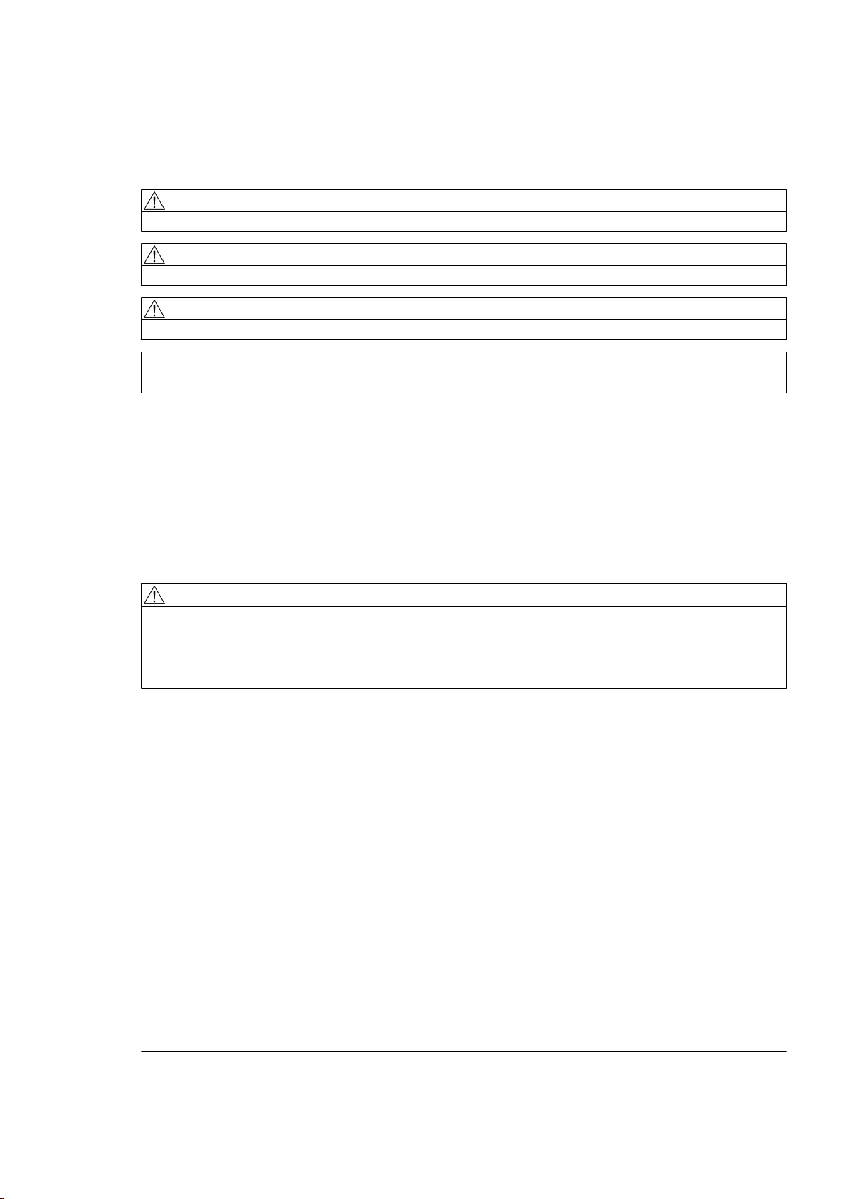
Table 2-1 Symbols and markings
Points labelled on the gear unit Symbol Coloured markings
Earth connection point
Air relief point yellow
Oil filling point yellow
Oil draining point white
Oil level indicator red
Oil level measurement red
Oil overflow
Connection point for vibration monitoring
Lubrication point red
Apply grease
Lifting eye
Gear unit 5118en
14 Operating Instructions 10/2017
Safety instructions
2.4 General warnings and symbols
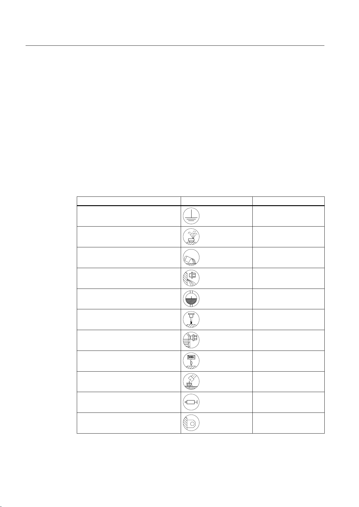
Points labelled on the gear unit Symbol Coloured markings
Eye bolt
Do not unscrew
Alignment surface, horizontal
Alignment surface, vertical
These symbols indicate the oil level check‐
ing procedure using the oil dipstick.
These symbols indicate that the oil dip‐
stick must be firmly screwed in.
2.4 General warnings and symbols
The following table contains general warnings and their associated symbols.
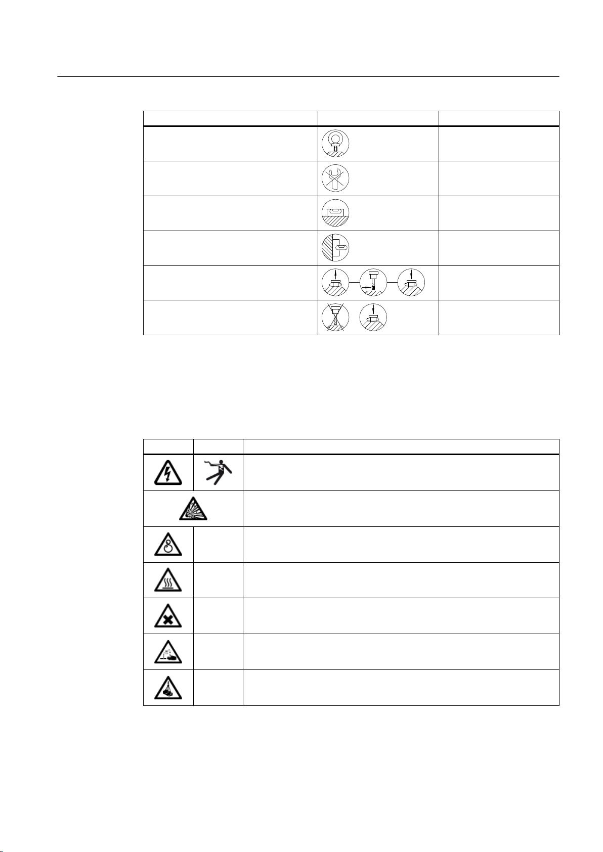
Table 2-2 General warnings
ISO ANSI Warning
Warning - hazardous electrical voltage
Warning - explosive substances
--- Warning - entanglement hazard
--- Warning - hot surfaces
--- Warning - substances that can irritate or which are hazardous to health
--- Warning - caustic substances
--- Warning - suspended load
Gear unit 5118en
Operating Instructions 10/2017 15
Safety instructions
2.5 Special types of danger and personal protective equipment
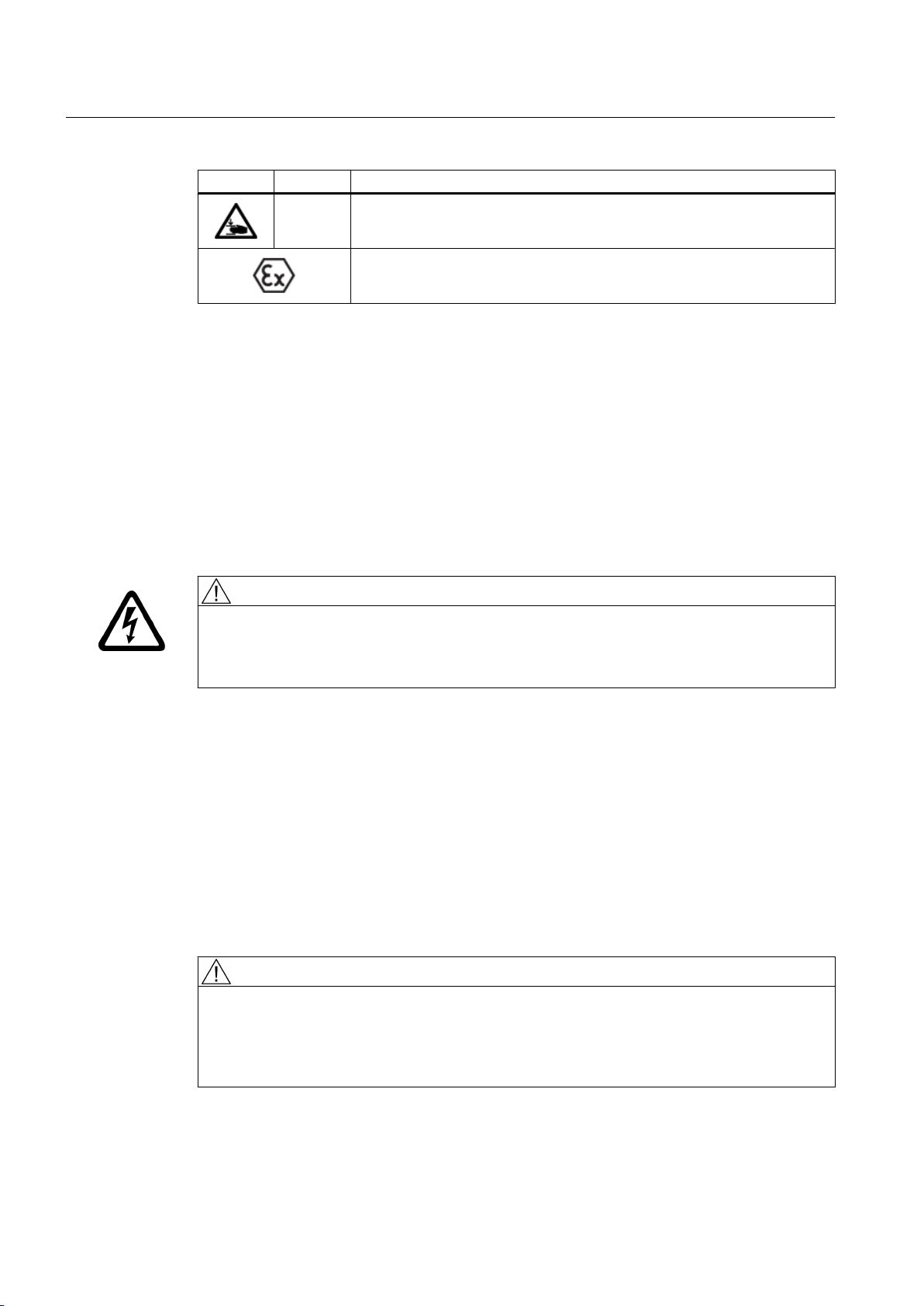
ISO ANSI Warning
--- Warning - hand injuries
ATEX certification
2.5 Special types of danger and personal protective equipment
Requirements
Fulfil the following requirements before commencing work on the gear unit:
● Ensure that the oil pressure lines are depressurised.
● Only perform work on the gear unit when it is not in operation.
● Disconnect electrical systems from the power supply.
Electric shock
Live parts can cause electric shock.
Ensure that the entire plant is de-energised before starting electrical installation work.
Protective equipment
Wear the following personal protective equipment when handling the gear unit:
● Safety shoes
● Overalls
● Helmet
● Safety gloves
● Safety goggles
Risk of eye injury
Small foreign particles such as sand or dust can enter the cover plates of the rotating parts
and be hurled back by them.
DANGER
WARNING
Wear safety goggles.
Gear unit 5118en
16 Operating Instructions 10/2017
Dangers during operation
Damage to the gear unit is possible.
Switch the gear unit to standstill immediately if inexplicable changes are noticed during
operation. Such changes may include unusual gear unit noise or a significant increase in
operating temperature.
WARNING
Risk of falling
There is an increased risk of falling when standing or walking on the gear unit during operation.
Only walk or stand on the gear unit and its mounted components for maintenance and repair
work when it is at a standstill. Do not walk or stand on shaft ends, protection covers, mounted
components or pipes.
WARNING
Danger to life through rotating or moving parts
There is danger that rotating or moving parts may catch hold of you or pull you in.
Safety instructions
2.5 Special types of danger and personal protective equipment
Secure rotating and/or moving parts against contact using safeguards.
Surface temperature
The surface temperatures of the gear unit can become very extreme depending on the
operating conditions.
Risk of burns
Possible risk of serious burn injury from hot surfaces (> 55 °C).
Wear suitable protective gloves and protective clothing.
Risk of scalding
Risk of serious injury possible through escaping hot operating media when these are being
changed.
Wear suitable protective gloves, safety goggles and protective clothing.
WARNING
WARNING
WARNING
Danger due to low temperatures
Possible risk of serious injuries due to frost (pain, numbness, frostbite) on cold surfaces
(< 0 °C).
Wear suitable protective gloves and protective clothing.
Gear unit 5118en
Operating Instructions 10/2017 17
Safety instructions
2.6 Intended use
Chemical substances
Injuries can be sustained when using chemical substances.
Risk of chemical burns due to chemical substances
There is a risk of chemical burns when handling aggressive cleaning agents.
Please observe the manufacturer's guidelines on how to handle cleaning agents and solvents.
Wear suitable protective equipment (gloves, safety goggles). Please use binding agents to
immediately clear up any spilt solvent.
Risk of injury due to chemically aggressive operating materials
There is a risk of injury to eyes and hands when handling chemically aggressive operating
materials.
Please observe the safety instructions in the data sheets of the oil used. Wear suitable
protective equipment (gloves, safety goggles). Use an oil-binding agent to immediately clean
up spilt oil.
WARNING
CAUTION
Danger of explosion
An explosion may occur in a potentially explosive atmosphere.
DANGER
Danger of explosion through ignition of a potentially explosive atmosphere
Danger to life through ignition of a potentially explosive atmosphere possible when operating
the gear unit
Do not use the gear unit in potentially explosive atmospheres.
2.6 Intended use
Only use the gear unit according to the conditions specified in the service and delivery contract
and the technical data in the annex (Page 105). Deviating operating conditions are considered
improper use. The user or owner of the machine or plant is solely liable for any resulting
damage.
Gear unit 5118en
18 Operating Instructions 10/2017
Safety instructions
2.6 Intended use
When using the gear unit please specifically observe the following:
● Do not make any modifications to the gear unit which go beyond the permissible handling
described in these operating instructions. This also applies to safety features designed to
prevent accidental contact.
● Only ever use original spare parts.
Other spare parts are not tested and approved by Flender. Non-approved spare parts may
possibly change the design characteristics of the gear unit and thus impair its active or
passive safety.
Flender will accept no liability or warranty whatsoever for damage occurring as a result of
the use of non-approved spare parts. The same applies to any accessories which were not
supplied by Flender.
If you have any queries, please contact Customer Services (Page 97).
WARNING
Risk of falling
Risk of possible serious injury through falling.
Only walk or stand on the gear unit for maintenance and repair work when it is at a standstill.
Do not walk or stand on shaft ends, protection covers, mounted components or pipes.
Gear unit use
When using the gear unit, please observe the following basic rules:
● Ensure that the gear unit is operationally safe.
● The gear unit should only be operated, maintained or repaired by authorised, trained and
suitably qualified personnel.
● The relevant work safety and environmental protection regulations must be complied with
at all times during transport, assembly, dismantling, operation, maintenance and servicing.
● The outside of the gear unit must not be cleaned using high-pressure cleaning equipment.
● No welding work must be performed on the gear unit or on parts connected to it. The gear
unit and any parts connected to it must not be used as an earthing point for electric-welding
operations. Gearing and rolling-contact bearings might be irreparably damaged by welding.
● Perform potential equalisation in accordance with the applicable regulations and guidelines.
If no threaded holes are available on the gear unit for an earth connection, please take
suitable measures. This work must always be done by specialist electricians.
● In the case of gear units that are operated in combination with electrical machines that
generate current or through which current flows (e.g. motors and generators), take
measures to ensure that no current can flow through the gear unit.
Current flowing through the gear unit can result in irreparable damage to rolling-contact
bearings and gearing. Short circuits, voltage flashovers and deposits of conductive dust,
for example, can all allow current to flow.
Use insulators and earth the gear unit properly.
● When removing any protective devices, retain their fixings safely.
● Removed protective devices must be re-fitted prior to starting up.
Gear unit 5118en
Operating Instructions 10/2017 19

Safety instructions
2.6 Intended use
● Pay attention to the notices attached to the gear unit such as the rating plate, direction
arrow symbol etc. Notices must not be concealed by paint or dirt. Replace missing plates.
● Bolts which have been damaged during assembly or disassembly work must be replaced
with new ones of the same strength class and type.
DANGER
Danger to life due to live system
Death or serious injury will occur.
Always shut down the gear unit and any oil supply system (whether separate or mounted on
the gear unit) before you carry out any work. Secure the drive unit against being operated
accidentally as follows:
● Turn off the key-operated switch.
● Remove the fuses in the power supply.
● Attach a notice to the start switch, clearly stating that work is being carried out on the gear
unit.
Ensure that the entire unit is load-free so that no danger is posed when you start to dismantle
components.
Reactivating the gear unit
When installing the gear unit in machines or systems, the machine or system manufacturers
must ensure that the regulations, notes and descriptions contained in these operating
instructions are incorporated in their own operating instructions.
Gear unit 5118en
20 Operating Instructions 10/2017

Description
3.1 General description
The FLENDER® gear unit (referred to below simply as "gear unit") described in these operating
instructions has been developed to drive a mixing system in general machinery construction.
This series of gear units is suitable for applications in the chemical, rubber and plastics
industries, for example.
The helical gear unit and the bevel helical gear unit are available as a two, three or multi-stage
unit. These are designed for horizontal mounting. The gear units can also be implemented
with two output shafts and several input shafts.
It can essentially be operated in both directions of rotation.
Designs
Various shaft arrangements (designs and directions of rotation) are possible for the gear unit.
The direction of rotation arrows indicate the dependency of the direction of rotation of the input
and output shafts. The versions and directions of rotation are specified in the dimension
drawing in the complete documentation for the gear unit.
3
3.2 Output shaft versions
Information regarding the output version is provided in a separate data sheet and in the
dimension drawing in the complete gear unit documentation.
3.3 Housing
Introduction
The housing is made of steel. When specified, the housing can also be manufactured out of
cast iron.
The housing is a two-part component.
The gear unit housing has the following features:
● Attachment points for transporting the gear unit
● Inspection and assembly cover for oil filling and inspection
● Oil filling point for refilling with oil
● Oil sight glass, oil level indicator or dipstick for checking the oil level
Gear unit 5118en
Operating Instructions 10/2017 21

Description
3.3 Housing
● Oil drain screw or oil drain valve for changing the oil
● Air filter or wet-air filter for ventilation and bleeding
Further information
Additional information and a detailed illustrated description of the gear unit can be found in the
dimension drawing provided in the complete gear unit documentation.
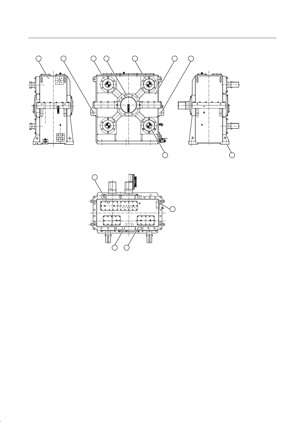
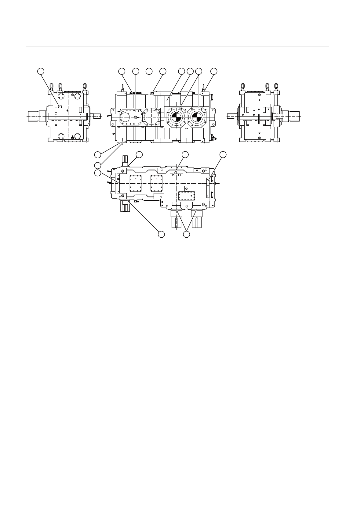
Gear unit equipment
The diagram below shows the gear unit equipment on type H2SH 24 (SOND 622) units:
① Cover ⑥ Alignment surfaces
② Inspection and assembly cover ⑦ Lifting eyes
③ Housing ⑧ Gear unit fastening
④ Rating plate ⑨ Shaft seal
⑤ Cover ⑩ Alignment thread
Figure 3-1 Gear unit equipment for type H2SH 24 (SOND 622) gear units
The diagram below shows the gear unit equipment for type M1S x 315 gear units:
22 Operating Instructions 10/2017
Gear unit 5118en
Description
3.3 Housing
① Rating plate ⑥ Gear unit fastening
② Lifting eyes ⑦ Shaft seal
③ Cover ⑧ Alignment surfaces
④ Cover ⑨ Inspection and assembly cover
⑤ Housing
Figure 3-2 Gear unit equipment for type M1S X 315 gear units
The diagram below shows the gear unit equipment for type H3SX gear units:
Gear unit 5118en
Operating Instructions 10/2017 23
Description
3.4 Oil supply to the gear unit
① Rating plate ⑥ Sling swivels
② Inspection and assembly cover ⑦ Alignment surfaces
③ Cover ⑧ Shaft seal
④ Housing ⑨ Alignment thread
⑤ Cover ⑩ Gear unit fastening
Figure 3-3 Gear unit equipment for type H3SX gear units
Further information
Additional information and a detailed illustrated description of the gear unit can be found in the
dimension drawing provided in the complete gear unit documentation.
3.4 Oil supply to the gear unit
Introduction
The oil supply to the various gear unit components can be implemented using the following oil
supply variants:
● Splash lubrication
● Pressure lubrication
● Combination of both oil supply variants
24 Operating Instructions 10/2017
Gear unit 5118en

3.4.1 Splash lubrication
Unless otherwise agreed by contract, the gearing and rolling-contact bearings are supplied
with an adequate quantity of oil by splash lubrication.
3.4.2 Pressure lubrication
At high input speeds or high gear circumferential velocities, depending on the particular
contract, splash lubrication can be supplemented or replaced by pressure lubrication.
With pressure lubrication, the rolling-contact bearings and gears located above the oil level
are adequately supplied with oil through pipes.
Designs
The following designs are possible:
● Mounted oil supply system
● Separate oil supply system???
Description
3.5 Bearing arrangement of the shafts
Further information
Additional information and a detailed illustrated description of the gear unit and the oil supply
system can be found in the dimension drawing in the complete gear unit documentation.
Additional information about the oil supply system can be found in the separate data sheet, in
the list of equipment and in the oil supply system operating instructions provided in the
complete gear unit documentation.
Mounted oil supply system with motor pump
The oil supply system is mounted on the gear unit and comprises the following components:
● Motor pump
● Double change-over filter
● Pressure monitor
● Piping
Further information
Additional information and a detailed illustrated description of the gear unit and the oil supply
system can be found in the dimension drawing in the complete gear unit documentation.
3.5 Bearing arrangement of the shafts
All shafts are mounted on rolling-contact bearings.
Gear unit 5118en
Operating Instructions 10/2017 25
Description
3.6 Shaft seal
3.6 Shaft seal
Introduction
Depending on requirements, shaft seals prevent oil from escaping from the gear unit or dirt
from entering the gear unit.
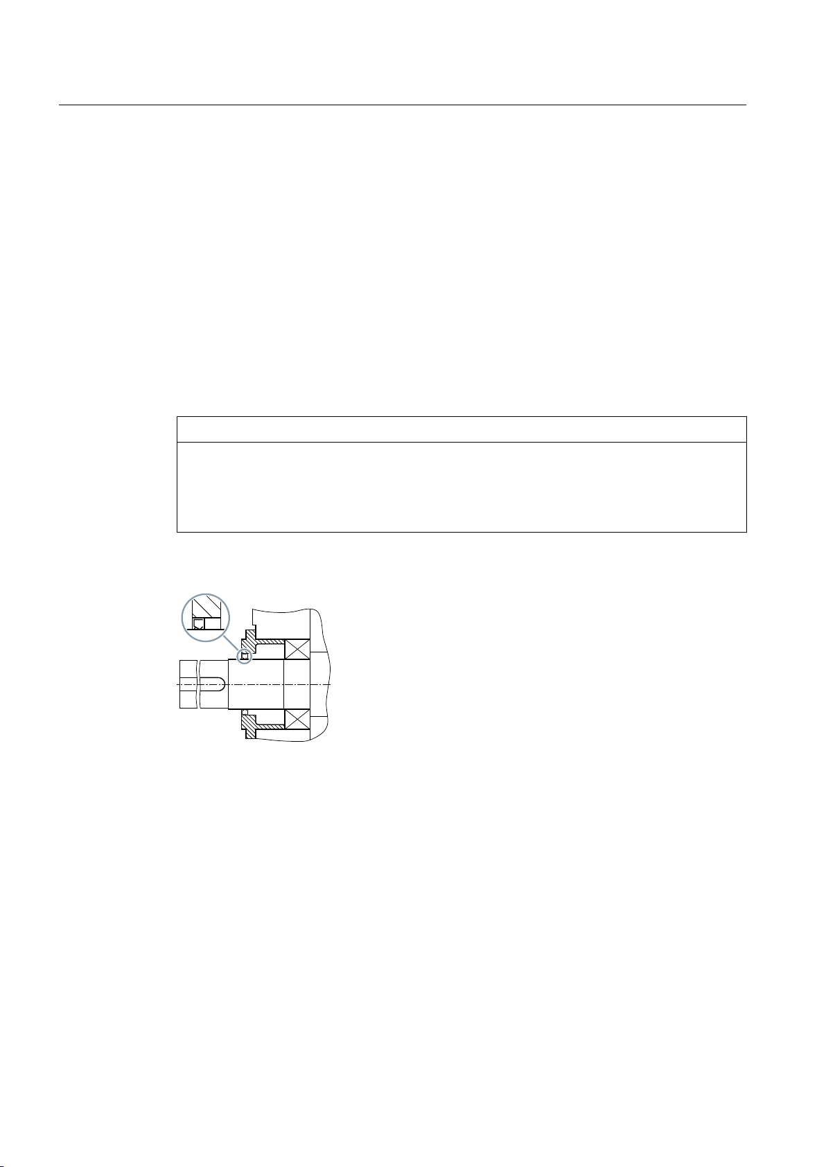
3.6.1 Rotary shaft sealing rings
Rotary shaft sealing rings are the standard seal used. Wherever possible, rotary shaft sealing
rings are equipped with an additional dust lip which protects the actual sealing lip against
external contaminants.
NOTICE
Irreparable damage to the rotary shaft sealing ring caused by high concentration of dust
A damaged rotary shaft sealing ring might not be able to effectively seal the gear unit.
In very dusty atmospheres, do not use rotary shaft sealing rings unless they have additional
protection.
The diagram below shows a rotary shaft sealing ring
Figure 3-4 Rotary shaft sealing ring
3.6.2 Labyrinth seals
Labyrinth seals as non-contact seals prevent shaft wear. They do not require any maintenance
and improve the temperature behaviour of the gear unit. Labyrinth seals can only be used with
pressure lubrication and with a reduced oil level.
The spare parts drawing and spare parts list specify whether or not the gear unit is equipped
with labyrinth seals.
A labyrinth seal is illustrated in the diagram below:
Gear unit 5118en
26 Operating Instructions 10/2017
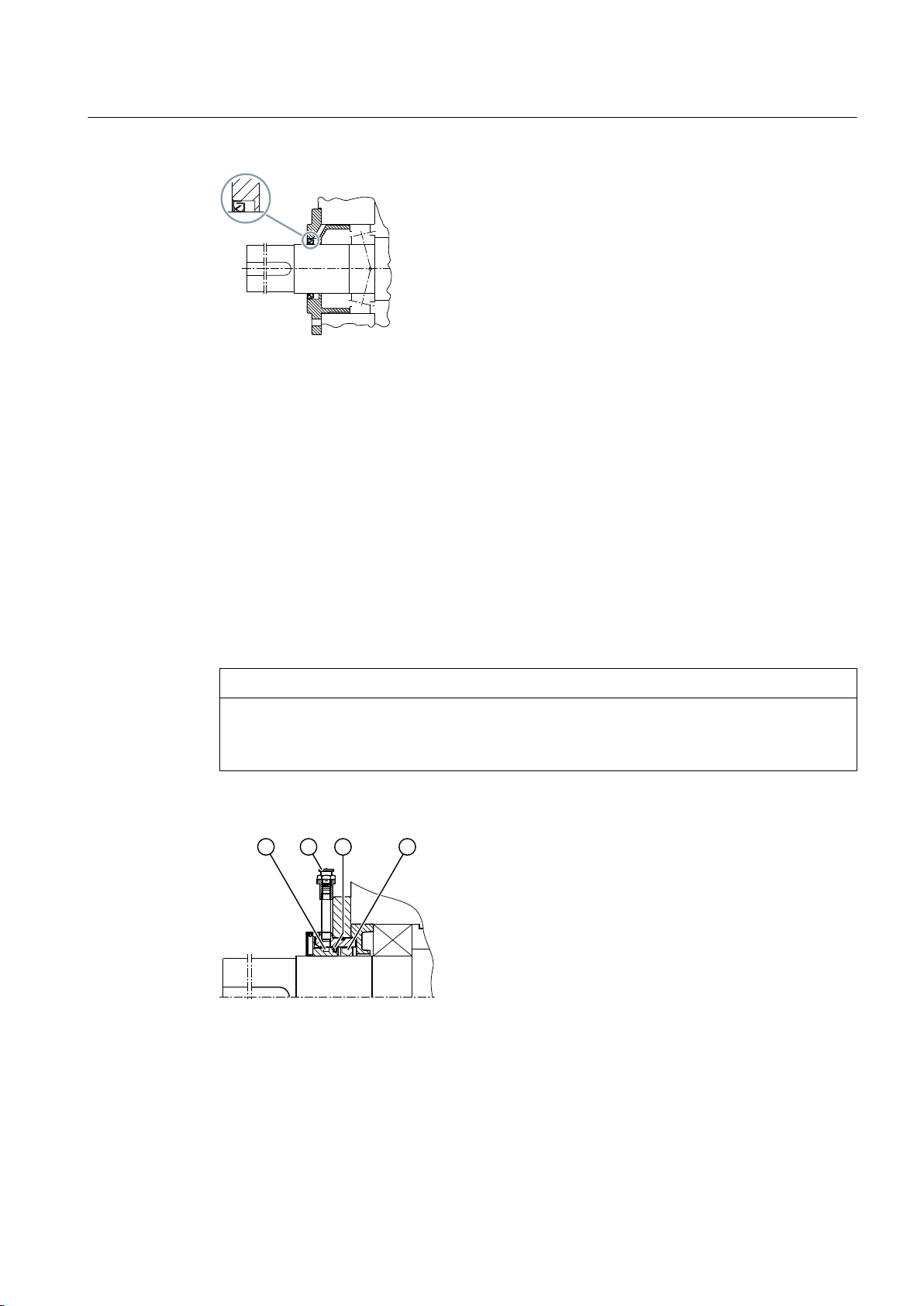
Figure 3-5 Labyrinth seal
To work reliably, labyrinth seals must be installed in stationary, horizontal positions without
dirty water or any substantial amount of dust. Overfilling the gear unit can result in leaks, the
same applies to oil with a high foam content.
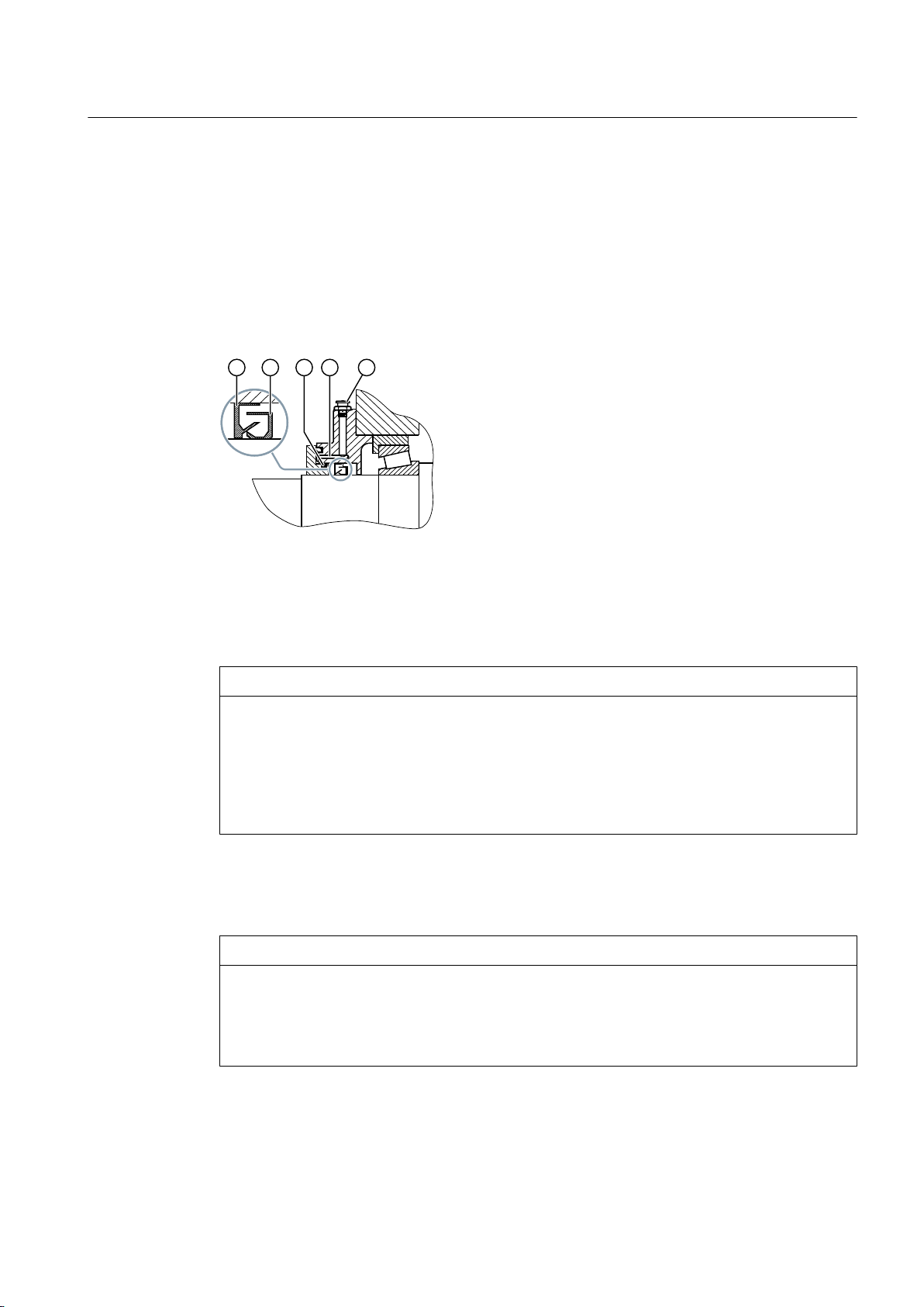
3.6.3 Taconite seal
The taconite seal is a combination of two sealing elements:
Description
3.6 Shaft seal
● Rotary shaft sealing ring to prevent the escape of lubricating oil
● Grease-filled dust seal (comprising a labyrinth and a lamellar seal) to allow operation of the
gear unit in extremely dusty environments
The taconite seal is ideal for use in dusty environments.
NOTICE
Gear unit leaks caused by poor sealing
Regrease the labyrinth seals at the specified regreasing intervals. The regreasing intervals
are specified in the Maintenance schedule (Page 86).
A taconite seal is illustrated in the diagram below:
① Labyrinth, filled with grease, can be regreased ③ Lamellar seal
② Grease nipple ④ Rotary shaft sealing ring
Figure 3-6 Taconite seal
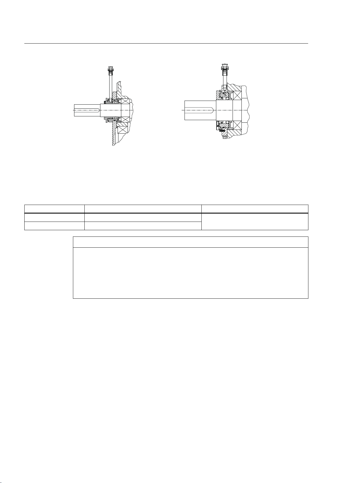
The following design variants of taconite seal are available:
Gear unit 5118en
Operating Instructions 10/2017 27
7DFRQLWH(7DFRQLWH)
Description
3.6 Shaft seal
Figure 3-7 Design variants of taconite seals
The various taconite seals are described in the following table:
Table 3-1 Taconite seal versions
Taconite seal versions Application Remarks
"E" All input shafts with or without fan
"F" Output shaft
● Regreasable labyrinth
NOTICE
Sparking, inadmissible temperature rise and shaft seal wear due to insufficient gap dimension
Sparking, inadmissible temperature rise and shaft seal wear possible due to insufficient gap
dimension
In the case of a shaft seal with taconite seals, ensure that the set gap dimension of 1
on the grease labyrinth is not changed when the input and output elements (e.g. coupling
parts) are mounted. Rotating and stationary parts must not touch.
3.6.4 Tacolab seal
Application
Only use Tacolab seals with pressure lubrication and with a reduced oil level.
+0.5
mm
Features
Tacolab seals are non-contact, low-maintenance seals that do not wear. It is not therefore
necessary to interrupt operation in order to service or replace them.
Gear unit 5118en
28 Operating Instructions 10/2017
Description
3.6 Shaft seal
The Tacolab seal is a combination of two sealing elements:
● Labyrinth seal comprising two labyrinth sealing rings to prevent the escape of lubricating
oil
● Grease-filled dust seal (comprising a labyrinth and a lamellar seal) to allow operation of the
gear unit in extremely dusty environments
A Tacolab seal is illustrated in the diagram below:
① Outer labyrinth seal ④ Labyrinth, filled with grease, can be regreased
② Inner labyrinth seal ⑤ Grease nipple
③ Lamellar seal
Figure 3-8 Tacolab seal
NOTICE
Sparking, inadmissible temperature rise and shaft seal wear due to insufficient gap dimension
Sparking, inadmissible temperature rise and shaft seal wear possible due to insufficient gap
dimension
If the shaft is sealed by Tacolab seals, make sure that the set gap dimension of 1
+0.5
mm at
the grease labyrinth is not altered when the input and output elements (e.g. coupling
elements) are installed. Rotating and stationary parts must not touch.
For reliable operation, Tacolab seals require a stationary, horizontal installation position
without any contact with dirty water ‐ or high dust levels. Overfilling the gear unit can result in
leaks, the same applies to oil with a high foam content.
NOTICE
Gear unit leaks caused by poor sealing
Gear unit leaks caused by poor sealing are possible.
Regrease the labyrinth seals at the specified regreasing intervals. The regreasing intervals
are specified in the Maintenance schedule (Page 85).
Gear unit 5118en
Operating Instructions 10/2017 29

Description
3.7 Cooling
Further information
Check in the spare parts drawing and the spare parts list as to whether the gear unit is equipped
with Tacolab seals.
3.7 Cooling
Introduction
The gear unit can be equipped with the following cooling equipment depending on
requirements:
● Fan
● Cooling coil
● Oil supply system mounted on gear unit
● Separate oil supply system
When installing the gear unit, make sure that unhindered convection across the housing
surface is possible in order to protect the gear unit against overheating.
3.7.1 Fan
Principle of operation
Generally, the fan is mounted on the high-speed shaft of the gear unit and is protected from
accidental contact using an air guide cover. The fan draws in air through the protective grille
of the air guide cover and blows it along the lateral air ducts on the gear unit housing. The fan
dissipates a certain amount of heat from the housing.
Improper use can damage the gear unit. Follow the instructions given below in order to protect
the gear unit against overheating:
● When you install the protective device for the coupling or similar on gear units that are
equipped with a fan, make sure that you leave sufficient clearance for cooling air to be
drawn into the fan.
The required clearance is specified in the dimension drawing in the complete
documentation for the gear unit.
● Make sure that the air guide cover is correctly fastened.
● Protect the air guide cover against damage by external components.
Gear unit 5118en
30 Operating Instructions 10/2017
 Loading...