

FLENDER ARPEX ARS-6, ARPEX ARH-8, ARPEX ARP-6, ARPEX ARC-10, ARPEX ARC-8 Operating Instructions Manual
...Page 1

FLENDER COUPLINGS
- - - - - - - - - - - - - - - - - - - - - - - - - - - - - - - - - - - - - - - - - - - - - - - - - - - - - - - - - - - - - -
ARPEX
- - - - - - - - - - - - - - - - - - - - - - - - - - - - - - - - - - - - - - - - - - - - - - - - - - - - - - - - - - - - - -
Operating instructions 8704 en
Edition 01/2019
- - - - - - - - - - - - - - - - - - - - - - - - - - - - - - - - - - - - - - - - - - - - - - - - - - - - - - - - - - - - - -
ARS-6, ARP-6, ARH-8, ARC-6/8/10, ARW-4/6, ARF-6
- - - - - - - - - - - - - - - - - - - - - - - - - - - - - - - - - - - - - - - - - - - - - - - - - - - - - - - - - - - - - -
flender.com
Page 2

Page 3

T
echnical data
T
T
1
General notes
FLENDER COUPLINGS
ARPEX
Safety instructions
ransport and storage
2
3
4
8704 en
echnical description
Operating instructions
Translation of the original operating instructions
Fitting
Start-up
Operation
Faults, causes
and remedy
5
6
7
8
9
ARS-6, ARP-6, ARH-8, ARC-6/8/10, ARW-4/6,
ARF-6
Maintenance
and repair
Spare parts,
customer service
Declarations
10
11
12
Edition 01/2019
Page 4
Legal notes
Warning note concept
This manual comprises notes which must be observed for your personal safety and for preventing material
damage. Notes for your personal safety are marked with a warning triangle or an "Ex" symbol (when applying
Directive 2014/34/EU), those only for preventing material damage with a "STOP" sign.
WARNING! Imminent explosion!
The notes indicated by this symbol are given to prevent explosion damage.
Disregarding these notes may result in serious injury or death.
WARNING! Imminent personal injury!
The notes indicated by this symbol are given to prevent personal injury.
Disregarding these notes may result in serious injury or death.
WARNING! Imminent damage to the product!
The notes indicated by this symbol are given to prevent damage to the product.
Disregarding these notes may result in material damage.
NOTE!
The notes indicated by this symbol must be treated as general operating information.
Disregarding these notes may result in undesirable results or conditions.
WARNING! Hot surfaces!
The notes indicated by this symbol are made to prevent risk of burns due to hot surfaces
and must always be observed.
Disregarding these notes may result in light or serious injury.
Where there is more than one hazard, the warning note for whichever hazard is the most serious is always used.
If in a warning note a warning triangle is used to warn of possible personal injury, a warning of material damage
may be added to the same warning note.
Qualified personnel
The product/system to which this documentation relates may be handled only by persons qualified for the work
concerned and in accordance with the documentation relating to the work concerned, particularly the safety and
warning notes contained in those documents.
Qualified personnel must be specially trained and have the experience necessary to recognise risks associated
with these products and to avoid possible hazards.
Proper use of Flender products
Observe also the following:
Flender products must be used only for the applications provided for in the catalogue and the relevant technical
documentation. If products and components of other makes are used, they must be recommended or approved
by Flender. The faultfree, safe operation of the products calls for proper transport, proper storage, erection,
assembly, installation, startup, operation and maintenance. The permissible ambient conditions must be
adhered to. Notes in the relevant documentations must be observed.
Trade marks
All designations to which the registered industrial property mark ® is appended are registered trademarks of
Flender GmbH. Other designations used in this document may be trademarks the use of which by third parties
for their own purposes may infringe holders’ rights.
Exclusion of liability
We have checked the content of the document for compliance with the hard and software described.
Nevertheless, variances may occur, and so we can offer no warranty for complete agreement. The information
given in this document is regularly checked, and any necessary corrections are included in subsequent editions.
Explanation regarding Machinery Directive 2006/42/EC
The couplings described here are “components” in accordance with the Machinery Directive and do not require
a declaration of incorporation.
Flender GmbH
Alfred-Flender-Straße 77
46395 Bocholt
GERMANY
Document number: 8704 en
01/2019 Subject to alterations
Copyright © Flender GmbH 2019
All rights reserved
Page 5

Contents
1. Technical data 7.....................................................
1.1 View of the various types 7.............................................................
2. General notes 8.....................................................
2.1 Introduction 8........................................................................
2.2 Copyright 8..........................................................................
3. Safety instructions 9.................................................
3.1 Obligations of the user 9...............................................................
4. Transport and storage 10.............................................
4.1 Scope of supply 10....................................................................
4.2 Transport 10..........................................................................
4.3 Storage of the coupling 10..............................................................
5. Technical description 11..............................................
5.1 General description 11.................................................................
5.2 Marking of the coupling parts for use in potentially explosive zones 12.........................
5.3 Operating conditions in potentially explosive areas 12.......................................
6. Fitting 13.............................................................
6.1 General information on fitting 13.........................................................
6.2 Instructions for machining the finished bore, axial fastening, set screws and balancing 14........
6.2.1 Finished bore 14.......................................................................
6.2.1.1 Parallel keyway 15.....................................................................
6.2.2 Axial fastening 15......................................................................
6.2.3 Set screws 15.........................................................................
6.2.4 Balancing 16..........................................................................
6.3 Fitting the coupling parts in case of shafthub connection with parallel key 16...................
6.4 Demounting the shafthub connection with parallel key 17...................................
6.5 Shrink connections 18..................................................................
6.5.1 Fitting 18.............................................................................
6.5.2 Demounting 19........................................................................
6.6 Clamping and slip hub connection 19.....................................................
6.6.1 Fitting 20.............................................................................
6.6.2 Demounting 21........................................................................
6.7 Split clamping hubs with halfshell 21.....................................................
6.7.1 Fitting 22.............................................................................
6.7.2 Demounting 22........................................................................
6.8 Split spacers 23.......................................................................
6.8.1 Fitting split spacers 23..................................................................
6.8.2 Fitting split spacers with creepcurrent insulation 25.........................................
6.9 "C", "D" and "F" flange screw connection 26...............................................
6.9.1 Fitting 26.............................................................................
6.10 Fitting of assemblybalanced couplings 27................................................
6.11 Pushing the units together 28............................................................
6.11.1 Inserting spacer or intermediate unit 28...................................................
6.12 Fitting the plate packs 29...............................................................
ARPEX 8704 en
Operating instructions 01/2019
5
Page 6

7. Startup 30...........................................................
7.1 Procedure before startup 30............................................................
8. Operation 30.........................................................
8.1 General operating data 30..............................................................
9. Faults, causes and remedy 31.........................................
9.1 General 31............................................................................
9.2 Possible faults 31......................................................................
9.3 Improper use 32.......................................................................
9.3.1 Possible faults when selecting the coupling and/or coupling size 32...........................
9.3.2 Possible faults when installing the coupling 32.............................................
9.3.3 Possible faults in maintenance 33........................................................
10. Maintenance and repair 33............................................
10.1 General 33............................................................................
10.2 Replacing plate packs 33...............................................................
11. Spare parts, customer service 34......................................
11.1 Spareparts stockage 34................................................................
11.2 Addresses for ordering spare parts and customer service 34.................................
12. Declarations 35.......................................................
12.1 EU declaration of conformity 35..........................................................
6
Operating instructions 01/2019
ARPEX 8704 en
Page 7
1. Technical data
Technical data, such as dimensions, weights, performance data, peak torques, operating life and
operating temperature ranges, etc., relating to the ARPEX couplings listed in these operating instructions
are documented in the product catalogues set out in table 1 and can be made available on request or
accessed on the Internet at any time (see back cover).
Where the coupling design deviates from that shown in the respective catalogue, an orderspecific
dimensioned drawing containing all the required technical data is enclosed with the delivery.
Table 1: Assignment product catalogues
Series ARS‐6 ARP‐6 ARH‐8 ARC‐8/10 ARW‐4/6 ARF‐6
Catalogue-No. MD 10.1 MD 10.1 K430 MD 10.1 MD 10.1 MD 10.1
These data together with the contractual agreements on the coupling determine the limits of its proper use.
Limited temperature ranges apply to use in potentially explosive environments in
accordance with Directive 2014/34/EU. The classification in temperature classes is
shown in item 5.3, "Conditions of use".
For sustained faultfree operation the coupling must be designed with an application
factor appropriate to the application. In the event of a change in operating conditions
(output, speed, changes to the prime mover and driven machine) the design must
always be checked.
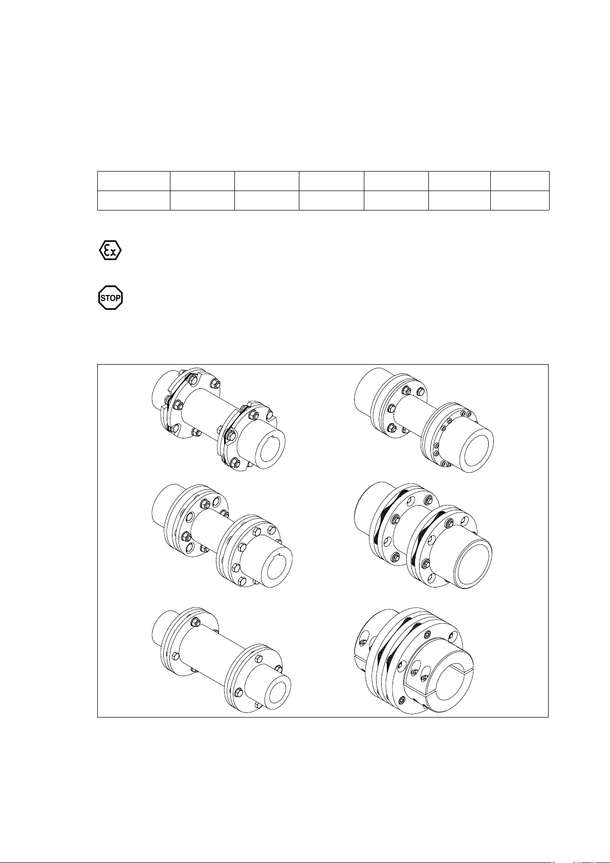
1.1 View of the various types
ARS‐6
ARH‐8
ARP‐6
ARC‐6/8/10
Fig. 1: View of the various types
ARPEX 8704 en
Operating instructions 01/2019
ARW‐4/6
ARF‐6
7
Page 8

2. General notes
2.1 Introduction
These instructions are an integral part of the delivery of the coupling and must be kept in its vicinity for
reference at all times.
All persons carrying out work on the coupling must have read and understood these
instructions and must adhere to them. Flender accepts no responsibility for damage
or disruption caused by disregard of these instructions.
The "FLENDER coupling" described in these instructions has been developed for stationary use in
general engineering applications. The coupling serves to transmit power (torque and speed) between two
shafts or flanges connected by this coupling.
The coupling has been manufactured in accordance with the state of the art and is delivered in a condition
for safe and reliable use. Any changes on the part of the user which may affect safety and reliability are
prohibited. This applies equally to safety features designed to prevent accidental contact.
The coupling complies with the requirements in Directive 2014/34/EU.
The coupling must be used and operated strictly in accordance with the conditions laid down in the contract
governing performance and supply.
The coupling is designed only for the application described on the orderspecific drawing of the coupling.
Other operating conditions are regarded as incorrect and must be contractually agreed.
For any damage resulting therefrom only the user or operator of the machine or plant is responsible.
The coupling described in these instructions reflects the state of technical development at the time these
instructions went to print.
In the interest of technical progress we reserve the right to make changes to the individual assemblies and
accessories which we regard as necessary to preserve their essential characteristics and improve their
efficiency and safety.
2.2 Copyright
The copyright to these operating instructions is held by Flender.
These instructions must not be wholly or partly reproduced for competitive purposes, used in any
unauthorised way or made available to third parties without our agreement.
Technical enquiries should be addressed to the following factory or to one of our customer services:
Flender GmbH
Schlavenhorst 100
46395 Bocholt
Tel.: +49 (0)2871 / 92-0
Fax: +49 (0)2871 / 92-2596
8
Operating instructions 01/2019
ARPEX 8704 en
Page 9

3. Safety instructions
Any changes on the part of the user are not permitted. This applies equally to safety
features designed to prevent accidental contact.
3.1 Obligations of the user
• The operator must ensure that all persons involved in installation, operation, maintenance and repair
have read and understood these operating instructions and comply with them at all times in order to:
─ avoid injury or damage,
─ ensure the safety and reliability of the coupling,
─ avoid disruptions and environmental damage through incorrect use.
• During transport, assembly, installation, demounting, operation and maintenance of the unit, the
relevant safety and environmental regulations must be complied with at all times.
• The coupling may only be operated, maintained and/or repaired by persons qualified for the work
concerned (see "Qualified personnel" on page 3 of this manual).
• All work must be carried out with great care and with due regard to safety.
• All work on the coupling must be carried out only when it is at a standstill. The drive unit must be secured
against being switched on accidentally (e.g. by locking the key switch or removing the fuses from the
power supply). A notice should be attached to the ON switch stating clearly that work is in progress.
• The coupling must be fitted with suitable safeguards to prevent accidental contact. The operation of the
coupling must not be impaired by the safeguard.
For the use in potentially explosive environments the protective equipment must
comply at least with type of protection IP2X.
• The drive unit must be shut down as soon as changes to the coupling are detected during operation.
• If the coupling is intended for installation in plant or equipment, the manufacturer of such plant or
equipment must ensure that the contents of the present operating instructions are incorporated in his
own instructions.
• Spare parts must be obtained from Flender (see section 11, "Spare parts, customer service").
ARPEX 8704 en
Operating instructions 01/2019
9
Page 10
4. Transport and storage
Observe the instructions in section 3, "Safety instructions".
4.1 Scope of supply
The products supplied are listed in the dispatch papers. Check on receipt to ensure that all the products
listed have actually been delivered. Parts damaged during transport or missing parts must be reported in
writing immediately. After consulting Flender an expert is to be called in.
A damaged coupling becomes an explosion hazard. Operating the coupling with
damaged coupling parts is not permitted in potentially explosive environments in
accordance with Directive 2014/34/EU.
4.2 Transport
When transporting the unit, use only lifting and handling equipment of sufficient
loadbearing capacity.
The coupling must be transported using suitable transport equipment only.
Different forms of packaging may be used depending on the size of the coupling and method of transport.
Unless otherwise agreed, the packaging complies with the HPE Packaging Guidelines.
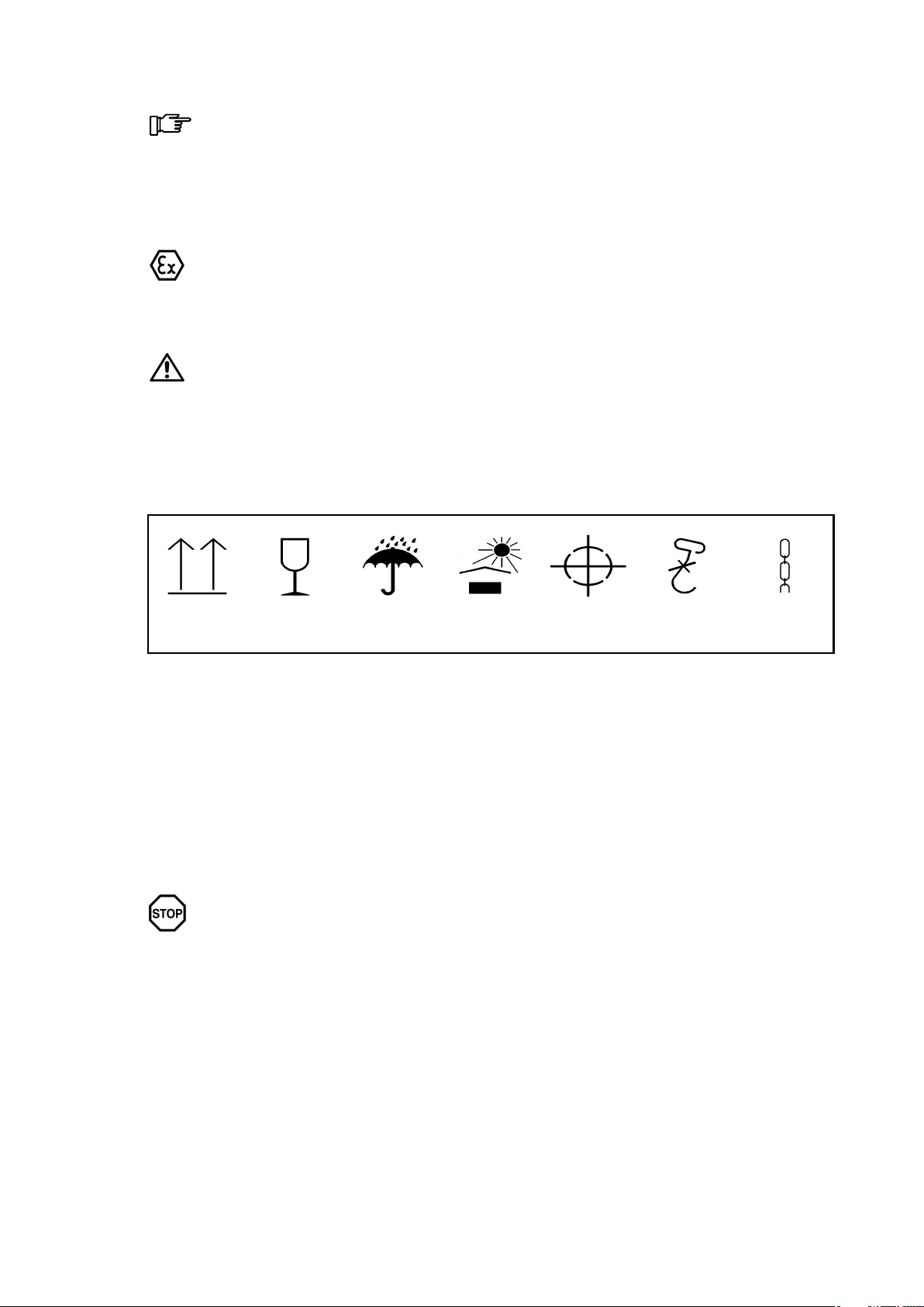
The symbols marked on the packing must be observed at all times. These have the following meanings:
Top Fragile Keep dry Keep cool Centre of
Fig. 2: Transport symbols
4.3 Storage of the coupling
The coupling is delivered in a preserved condition and can be stored in a covered, dry place for up to
6 months. If the unit is to be stored for a longer period, it should be treated with a longterm preservative
agent (Flender must be consulted).
Correctly stored couplings retain their properties unchanged. Unfavourable storage conditions and
improper treatment will negatively affect the physical properties of the coupling. Such negative effects may
be caused by e.g. the action of extreme temperatures or humidity.
The storage area must be dry and free from dust. The couplings must not be stored with aggressive
chemicals, acids, alkalis, etc.
Damp storage rooms (air humidity higher than 65 %) are not suitable. Ensure that no
condensation occurs.
gravity
Use no hand
hook
Attach
here
10
Operating instructions 01/2019
ARPEX 8704 en
Page 11
5. Technical description
5.1 General description
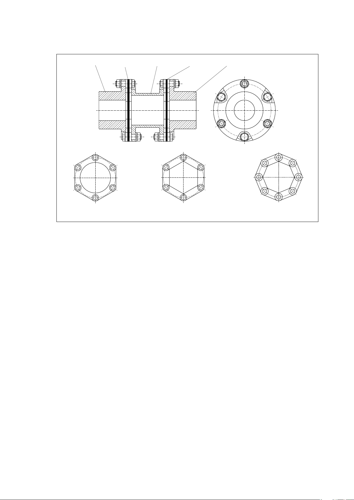
15432
687
Fig. 3: Hexagonal plate pack and octagonal plate pack
1 Hub
2 Plate pack
3 Spacer
4 Plate pack
5 Hub
6 Hexagonal ring plate pack
7 Hexagonal tie plate pack
8 Octagonal tie plate pack
ARPEX couplings are allsteel couplings. The plate packs are arranged between the flanges of the
coupling parts and bolted to them alternately.
The individual plates are threaded onto bushes and clamped together with a clipped on, internally bevelled
retaining rings. The retaining rings are held on by the expanded bush ends, which lie against the angled
face.
So constructed, the plate pack in ring plate pack designs forms a complete unit. In tie plate packs the
individual tie plates are crimped together to form plate strands and then pushed together in the shape of
a ring to form the plate pack.
Through this arrangement of the plate packs the ARPEX coupling is torsionresistant and transmits the
torque without circumferential backlash. In axial and radial direction the coupling is however still flexible
and can absorb axial, radial and angular misalignment of the coupled units.
Depending on the series, collar bolts and nuts or conical screw connections join the plate packs to sleeve
and coupling part flanges.
The size designation of the coupling indicates the outside flange diameter (d
the configuration of the plate pack ("6" = hexagonal) This information is prefixed by a letter combination
specifying the component parts of the coupling.
Example: ARS6 NHN 2556
ARPEX 8704 en
Operating instructions 01/2019
) of the coupling in mm and
a
Coupling with 2 hubs (N) and 1 "H" spacer (H) size 2556 with hexagonal plate pack in
the ARS6 series
11
Page 12
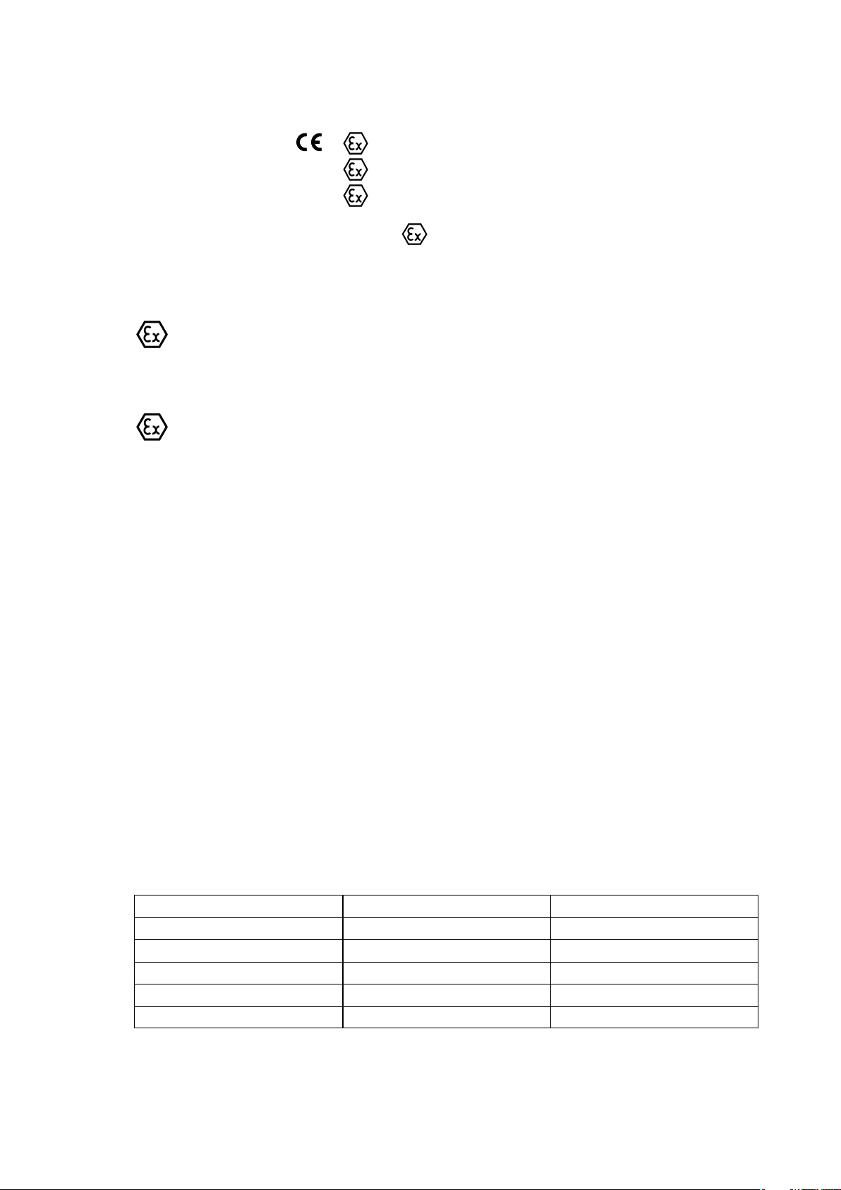
5.2 Marking of the coupling parts for use in potentially explosive zones
Couplings which are ordered in ATEX configuration, have the following marks on the outer circumference
of one of the coupling part (e.g. on the hub):
Flender GmbH
D 46393 Bocholt
ARPEX <year built>
II 2G Ex h IIC T6 … T2 Gb X
II 2D Ex h IIIC T85 °C … 250 °C Db X
I M2 Ex h Mb X
All component parts must also be marked
packaging only need be marked).
If, in addition to the CE mark, the letter "U" together with the Flender order number has been stamped on,
the coupling part has been delivered by Flender un or prebored.
Flender supplies unbored and prebored couplings with CE marking only under the
condition that the customer assumes the responsibility and liability for correct
refinishing in a declaration of exemption.
5.3 Operating conditions in potentially explosive areas
The machines connected by the coupling must be earthed by an earth leakage
resistance < 10
6
Ω.
If coated couplings are used in potentially explosive areas, the requirements made of
the conductivity of the coating and the limitation on the thickness of the coat applied
must be observed in accordance with standard "DIN EN 80079-36". Where coatings
have a thickness less than 200 μm, no electrostatic charge is to be expected.
If they are to be used below ground in potentially explosive areas the couplings must
only be used with drive motors, which can be switched off on occurring of an
explosible atmosphere.
(in the case of small components, if necessary, the
• Equipment group I (underground applications, mining)
─ Category M2 (coupling is not approved for equipment category M1).
• Equipment category II (use above ground, industry)
─ Categories 2 and 3 (coupling is not approved for equipment category 1).
─ Material group G (areas, in which there are explosible gas, vapour, mist, air mixtures),
zones 1 and 2 (coupling is not approved for use in zone 0).
─ Material group D (areas where dust can form explosible atmospheres),
Zones 21 and 22 (coupling is not approved for equipment category 20).
─ Explosion group IIC (Explosion groups IIA and IIB are included in IIC).
─ The permissible temperature classes and/or maximum surface temperatures are assigned as
a function of the maximum ambient temperature occurring in the immediate vicinity of the coupling
(see table 2).
Table 2: Temperature classes
Ambient temperature Temperature class Max. surface temperature
- 40 °C up to max. + 230 °C T2 < 280 °C
- 40 °C up to max. + 150 °C T3 < 200 °C
- 40 °C up to max. + 85 °C T4 < 135 °C
- 40 °C up to max. + 50 °C T5 < 100 °C
- 40 °C up to max. + 35 °C T6 <85°C
12
Operating instructions 01/2019
ARPEX 8704 en
Page 13
6. Fitting
Observe the instructions in section 3, "Safety instructions"!
6.1 General information on fitting
Fitting work must be done with great care by qualified specialist personnel.
As early as during the planning phase it must be ensured that sufficient space is available for installation
and subsequent care and maintenance work.
Adequate lifting equipment must be available before beginning the fitting work.
The tightening torques specified in tabels 4, 5 and 6 must always be adhered to. Any
other tightening torques may result in accelerated wear and damage to the coupling.
Failure to observe the instructions in this section may result in breakage of the
coupling.
Danger to life from flying fragments.
A damaged coupling becomes an explosion hazard. Operating the coupling with
damaged coupling parts is not permitted in potentially explosive environments in
accordance with Directive 2014/34/EU.
Under no circumstances must welding work be done on the coupling or coupling
components, as this will negatively affect the physical property of the coupling.
If coated couplings are used in potentially explosive areas, the requirements made of
the conductivity of the coating and the limitation on the thickness of the coat applied
must be observed in accordance with standard "DIN EN 80079-36".
Where coatings have a thickness < 200 μm, no electrostatic charge is to be expected.
Where coatings are thicker than 200 μm, an electrostatic charge, e.g. by cleaning the
coupling, must be avoided.
At the customer’s express request Flender also supplies unbored or prebored coupling parts for couplings
which will not be operated in potentially explosive environments as set out in Directive 2014/34/EU. The
necessary refinishing must then be carried out in strict compliance with the following specifications and
with particular care!
Responsibility for carrying out the refinishing is borne by the customer. Flender will
accept no guarantee claims arising from unsatisfactory refinishing.
ARPEX 8704 en
Operating instructions 01/2019
13
Page 14
6.2 Instructions for machining the finished bore, axial fastening, set screws and balancing
6.2.1 Finished bore
Remove preservative agent from coupling parts.
Observe the manufacturer’s instructions for handling the solvent.
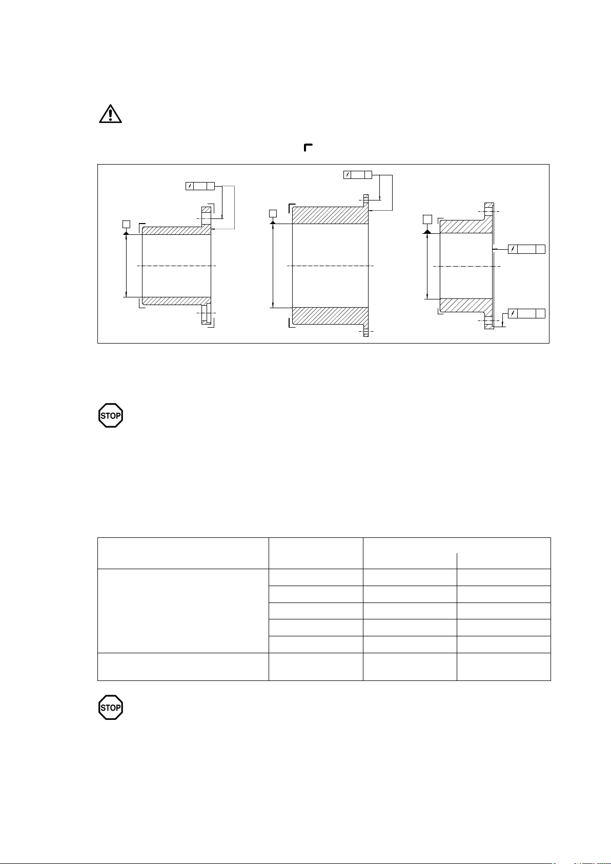
When machining the finished bore the parts must be carefully aligned.
The parts must be fitted on the marked faces (
1
AIT 7
) (see figure 4).
BIT 7
2
3
A
Ø D1
B
Ø D1
C
CIT 7
Ø D1
CIT 7
Fig. 4: Finished bore to ISO tolerances
1"N"-hub / "B"-hub
3"M"-hub
2"M"-hub
The maximum permissible bore diameters (see section 1, "Technical Data") are
designed for drivetype fastenings without taper action to DIN 6885/1 and must not
under any circumstances be exceeded. The finishmachined bores must be 100 %
checked with suitable measuring equipment.
If other shafthub connections (such as splined hub profiles, taper or stepped bores and drivetype
fastenings with taper action or other connections) are to be used instead of the drivetype fastenings
provided for, Flender must be consulted.
For drive by means of parallel keys the following fit pairs are prescribed for the bores (see table 3):
14
Table 3: Fit pairs
Type of fit Shaft tolerance
Interference fit with parallel-key
connection
Shrink fit without parallel-key connection
The assigned fits must be adhered to in order, on the one hand, to keep the play in the
shafthub connection as low as possible, depending on utilisation of the tolerance
zones, and, on the other, to keep the hub tension arising from the oversize within the
permissible load limit. Failure to adhere to the assigned fits may impair the shafthub
connection.
Bore tolerances
Reversing operation Setting-up operation
h6 P7 N7
k6 M7 H7
m6 K7 H7
n6 J7 H7
p6 H7 F7
to customer
specification
on request on request
Operating instructions 01/2019
ARPEX 8704 en
Page 15
6.2.1.1 Parallel keyway
The parallel keyways must be designed to suit the available parallel keys. For parallel keyways the
tolerance zone of the hub keyway width ISO P9 must be adhered to.
6.2.2 Axial fastening
A set screw or end plate must be provided to secure the coupling parts axially. If end plates are used,
Flender must be consulted with regard to machining the recesses in the coupling parts.
6.2.3 Set screws
To prevent damage to the shafts, the setscrew hole should be arranged on the parallel
keyway.
In exceptional cases the set screw must be offset 180° to the parallel keyway, if
because of the diameter of the drilled hole and hub core too little material is left
between the parallel keyway and the hub core (e.g. series ARS6, size 786).
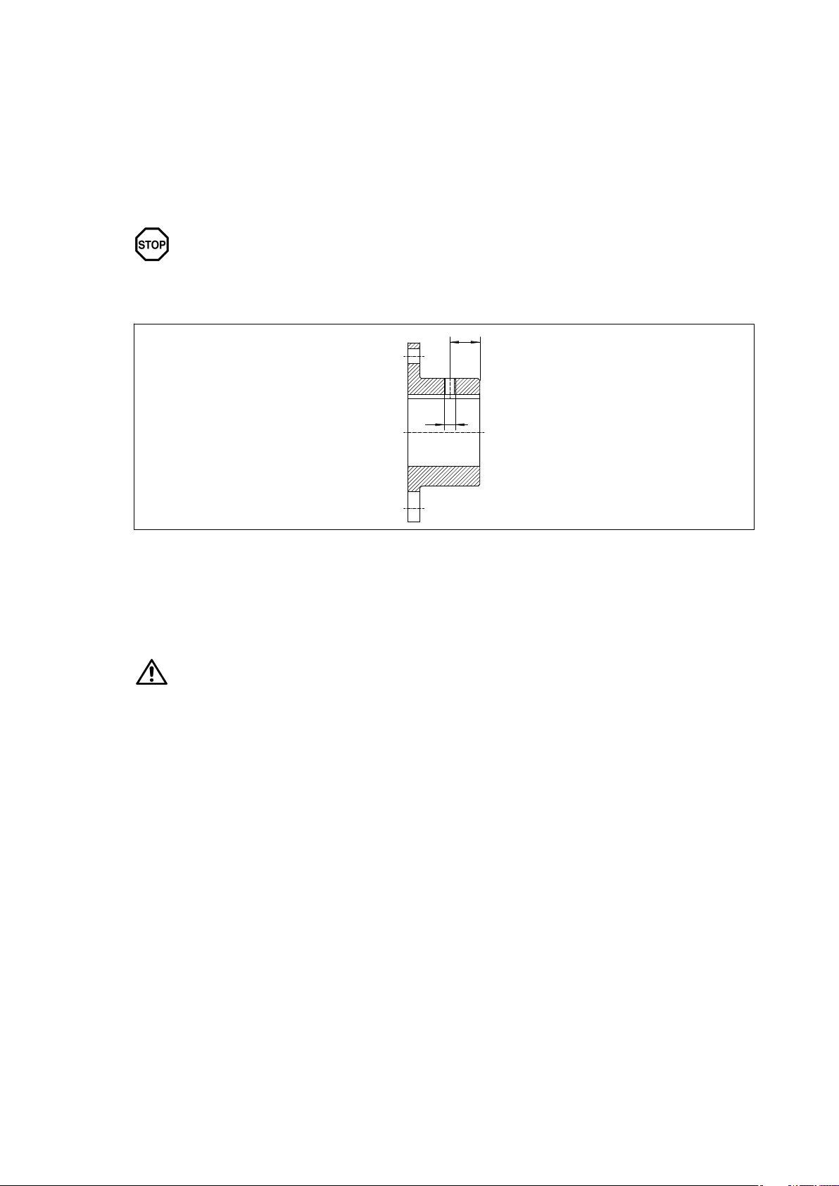
e
M
Fig. 5: Setscrew bore
The following guidelines must be observed:
The set screw should be inserted in the centre of the hub core (see figure 5). If this option is not possible,
care must be taken that the distance (e) is at least M x 1.5.
Use a threaded stud with cup point to DIN 916 for set screws.
The length of the set screw must be selected so that it fills the threaded hole, but does
not project from the hub (L
= M x 1.2).
min.
ARPEX 8704 en
Operating instructions 01/2019
15
Page 16
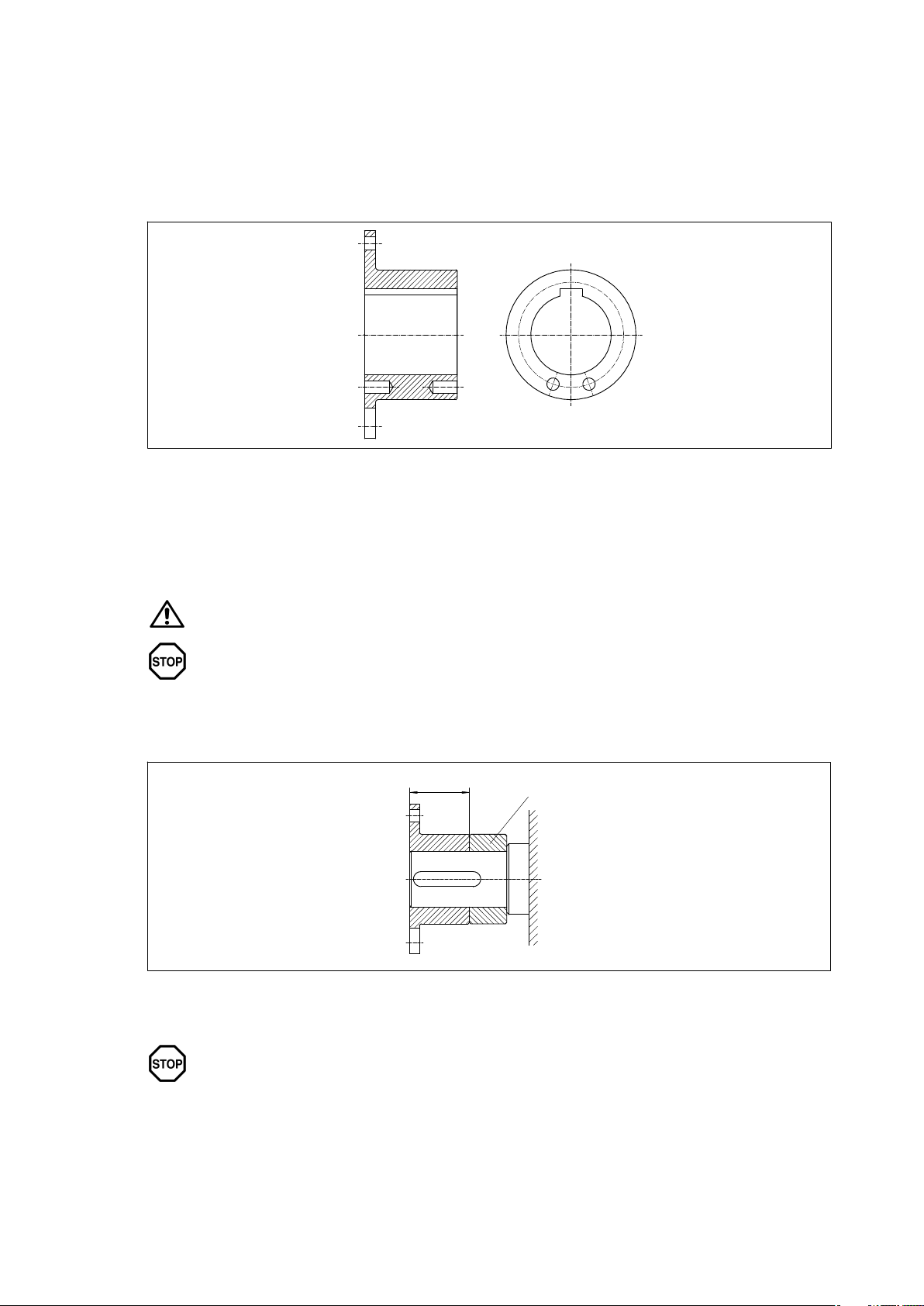
6.2.4 Balancing
Prebored couplings and/or prebored coupling parts are delivered unbalanced. It is recommended that
these parts are balanced to suit the application after finishboring (see DIN 740, DIN ISO 21940 part 1).
Balancing is normally done by drilling material away. To keep the amount of material to be removed to
a minimum, a largest possible balance radius must be selected (see figure 6).
Finishbored couplings and/or coupling parts are balanced according to the customer’s specifications.
Fig. 6: Arrangement of the balancing bore with onelevel balancing (balanced after machining the
keyway)
6.3 Fitting the coupling parts in case of shafthub connection with parallel key
Before beginning assembly the fitting bores and contact surfaces for rings, bushes, nuts and closefitting
bolts or taper pins and bushes (see item 6.12, "Fitting the plate packs" and/or separate assembly
instructions) must be cleaned of any rustpreventer. Likewise, the shaft ends must be carefully cleaned.
Observe the manufacturer’s instructions for handling the solvent.
The coupling parts must be fitted with the aid of suitable equipment to avoid damaging
the shaft bearings through axial joining forces. Always use suitable lifting equipment.
The shaft ends should not project from the inner sides of the hub. If necessary, the hubs can be adjusted
to the length of the shaft by fitting spacers or spacer rings (see figure 7). Axial fastening can be effected
by means of a set screw or end plate.
L1
1
Fig. 7: Spacer ring
16
1 Spacer ring
The set screws should be tightened only with a hexagon socket spanner to
DIN ISO 2936, without extension tube.
ARPEX 8704 en
Operating instructions 01/2019
Page 17
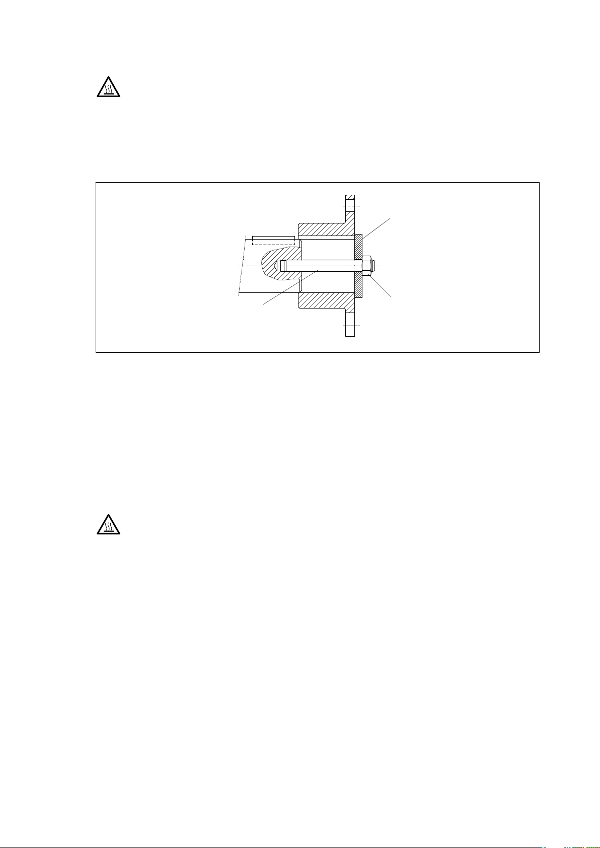
In case of hubs with a parallelkey connection fitting may be aided by slightly heating the coupling hubs
(maximum 150 °C).
Take precautions to avoid burns from hot parts.
Wear suitable protective gloves.
Hubs with transition fits and heated hubs can be pulled onto the slightly oiled shaft end with the aid of
a fitting device.
Screw threaded rod (the size of the thread depends on the shaft diameter) into the shaft end. Fit an
appropriately sized washer over the threaded rod. By screwing on and tightening a nut the hub is pushed
onto the shaft (see figure 8).
2
1
Fig. 8: Fitting the hub with threaded rod
1 Threaded rod
2 Washer
6.4 Demounting the shafthub connection with parallel key
If a coupling hub with parallelkey connection is to be pulled off the shaft, the plate packs must first be
demounted. Then, if necessary, the end plate can be demounted or the set screw loosened. With the aid
of a detaching device (threearmed pullingoff device) or by inserting a pullingoff device into the pullingoff
holes provided – if these are required in the order – pull the hub off the shaft end (see fig. 9 and 10).
In case of an interference fit the hub must, if necessary, be evenly slightly heated with a burner and carefully
pulled off the shaft, using a detaching device.
Take precautions to avoid burns from hot parts.
Wear suitable protective gloves.
Check the demounted parts to see if they can be reused and, if necessary, return them to Flender for
repair.
3
3 Nut
ARPEX 8704 en
Operating instructions 01/2019
17
Page 18
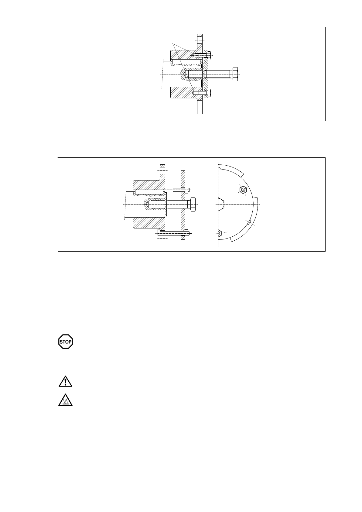
Fig. 9: Hub with tapped pullingoff holes
1 Pulling-off holes
1
Fig. 10: Threearmed pullingoff device (cannot be used for all hubs)
6.5 Shrink connections
6.5.1 Fitting
Cylindrical shrink fits are joined by heating the outer part. The correct joining temperature is calculated by
the manufacturer specifically for the order and is shown on the coupling drawing delivered with the unit.
To avoid premature locking the joining operation must be carried out quickly in a draughtfree area.
Care must be taken to keep transport distances short.
In the case of stepped shaft ends, when the hubs are pulled on, the locking bolts must
be removed from the threaded connections. When the hubs have been pulled on, the
locking screws must be screwed back in.
The surfaces to be joined must be absolutely clean and greasefree.
Observe the manufacturer’s instructions for handling the solvent.
Take precautions to avoid burns from hot parts.
Wear suitable protective gloves.
18
Operating instructions 01/2019
ARPEX 8704 en
Page 19
6.5.2 Demounting
The coupling hubs must be provided with one or more oil channels, depending on length and design. The
oil must be injected into the join by way of the oil connections the number of which corresponds to the
number of oil pumps. Axial misalignment is achieved by means of a separate hydraulic press or
mechanical pullingoff device.
Secure hub axially. Risk of injury from falling coupling parts.
6.6 Clamping and slip hub connection
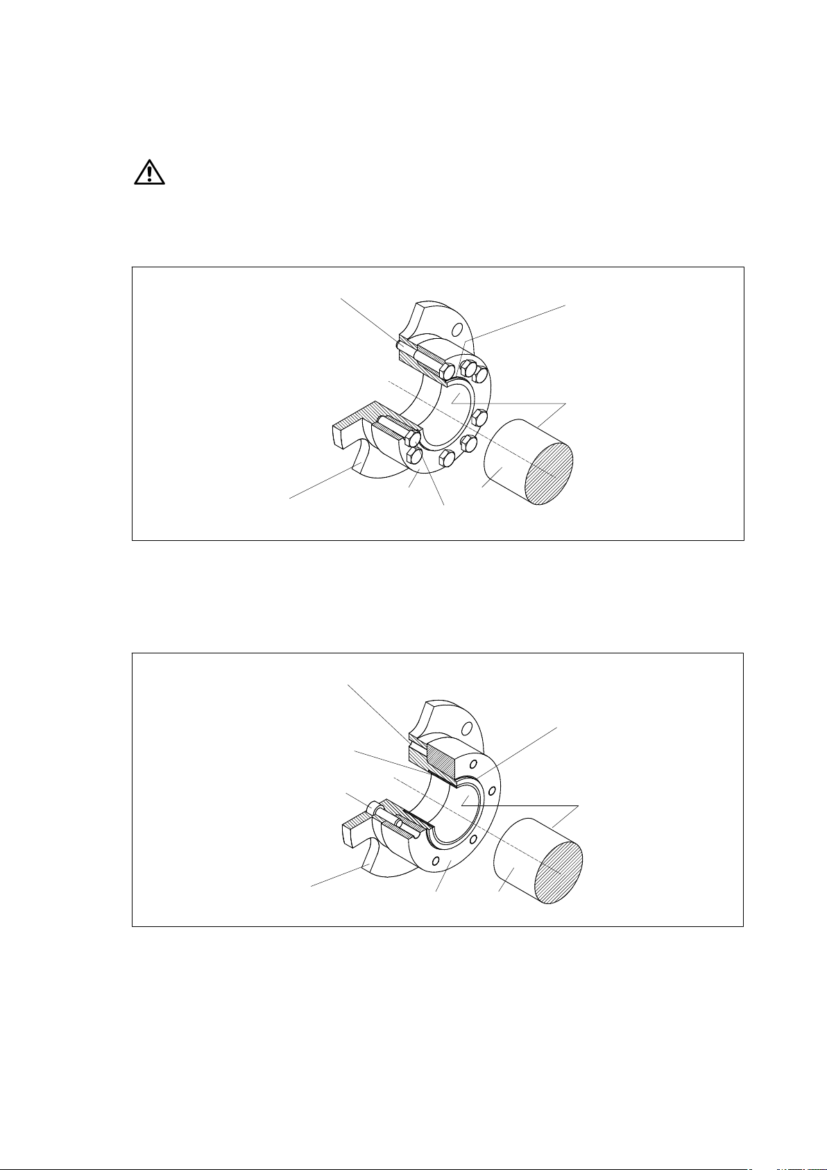
Forces are transmitted frictionally by the ARPEX clamping and slip hubs. The clamping or slip hubs are
delivered in an assembled condition (ready to fit) (see figs. 11 and 12).
1
4
5
Fig. 11: Clamping hub, type 124 (example: ARS6)
1 Tensioning bolt
2 Bevel surface "lubricated"
3 free of grease
4 Clamping hub
1
2
3
7
6
5 Clamping ring
6 Forcing-off bolt
7 Shaft
Fig. 12: Slip hub, type 125 (example: ARS6)
1 Forcing-off thread
2 Bronze bush
3 Bevel surface "lubricated"
4 free of grease
ARPEX 8704 en
Operating instructions 01/2019
3
2
5
4
6
87
5 Tensioning bolt
6 Clamping hub
7 Clamping ring
8 Shaft
19
Page 20
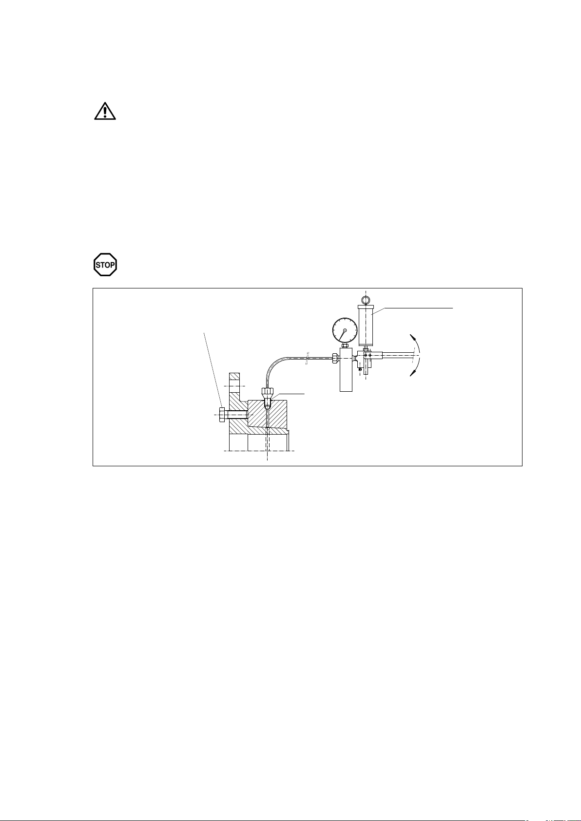
6.6.1 Fitting
During fitting the following procedure must be observed:
• Degrease the hub bore and shaft.
• Slightly loosen the tensioning bolts and pull the clamping ring off the hub slightly so that the clamping
ring sits loosely on it.
• Push the hub onto the shaft.
• Tighten the tensioning bolts evenly one after the other, going round several times until the clamping ring
lies evenly against the flange of the clamping or slip hub. The clamp connection is able to function when
the torque for tensioning bolts (quality 10.9) specified in table 5, "Tightening torques for connecting and
tensioning bolts" in item 6.8.1 has been reached and the clamping ring thus lies up against the hub
flange.
Hub bore and shaft must be absolutely clean and free of grease.
Observe the manufacturer’s instructions for handling the solvent.
Failure to observe these instructions may impair the function of the clamping and/or
slip hub.
3
1
Fig. 13: Demounting with highpressure pump
1 Forcing-off bolt ISO 4017
2 G1/4"
2
3 High-pressure pump
20
Operating instructions 01/2019
ARPEX 8704 en
Page 21
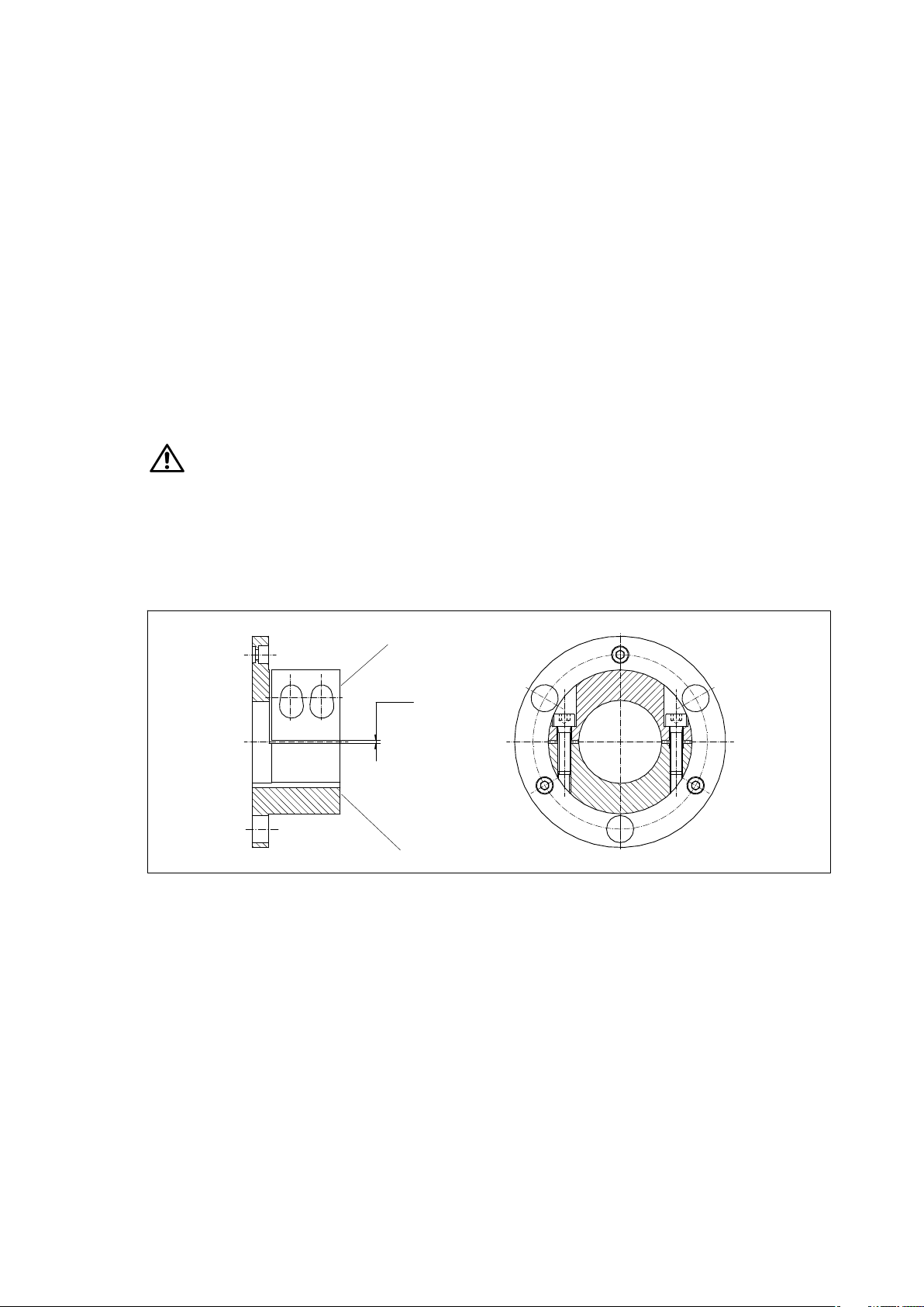
6.6.2 Demounting
Undo the tensioning bolts evenly one after the other. Each bolt must be loosened only half a turn per pass.
Unscrew all tensioning bolts 3 to 4 thread turns.
If the clamping ring does not come free off the clamping or slip hub by itself, forcingoff bolts to match the
number of available threads must be inserted in the ARPEX flange and evenly tightened until the clamping
ring comes free. Before once more pulling on the clamping ring, remove the bolts once more!
Clamping and slip hubs of type 124 (see Fig. 11) have, dependent on the size, already been equipped with
forcingoff bolts in the clamping ring. Before once more pulling on the clamping ring screw them back to
their original position!
If these actions do not work in case of larger clamping hubs, oil must be pumped by a highpressure pump
into the join between the clamping ring and the clamping hub to release the clamping ring. For this the
highpressure hose of the pump must be connected to the clamping ring via the G1/4" connecting thread
on the outer circumference (see Fig. 13).
Before reclamping remove the forcingoff bolts and reseal the G1/4" connecting thread, using the plug
supplied with the unit.
If the clamping ring is pulled off the clamping hub hydraulically, the bevel faces must be cleaned of
hydraulic oil and regreased with "Altemp Q NB 50" (Co. Klüber).
Released clampinghub connections do not have to be demounted and regreased before being
retensioned. If however the bevel faces still have to be regreased, the abovementioned lubricant must
be used.
Observe the manufacturer’s instructions for handling the solvent.
6.7 Split clamping hubs with halfshell
The halfshells are loosely bolted to the hubs (see figure 14).
Fig. 14: Split clamping hub with halfshell
1 Marking by numbers
2 Gap dimension
1
2
3
3 Marking by numbers
ARPEX 8704 en
Operating instructions 01/2019
21
Page 22
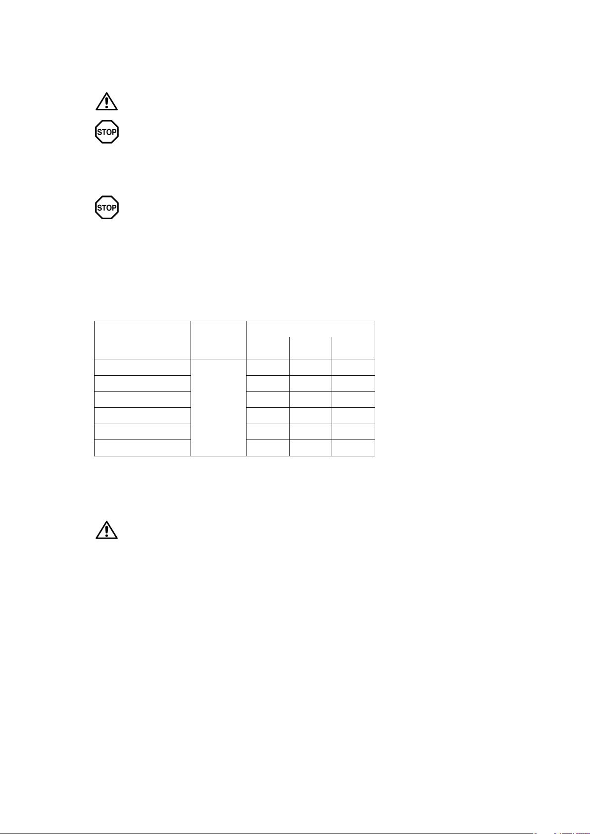
6.7.1 Fitting
Before fitting, the halfshells must be removed from the hubs and the holes carefully cleaned and
degreased using a suitable degreasing agent.
Place the clamping hubs on the shaft ends. The tension screws in the halfshell must first be evenly
screwed up only handtight.
Then, using a torque wrench, tighten the tension screws alternately in at least 3 passes (see table 4).
First pass: Tighten the clamping bolts to 30 % of the tightening torque (see table 4).
Second pass: Tighten the clamping bolts to 60 % of the tightening torque (see table 4).
Third pass: Tighten the clamping bolts to 100 % of the tightening torque (see table 4).
Table 4: Tightening torques for split clamping hubs with halfshell
Observe the manufacturer’s instructions for handling the solvent.
Do not interchange halfshells.
Check that the number markings (markingpunch number) at the side of the hub core
are identical (see Fig. 14).
Ensure the halfshells are evenly seated. Check the gap size is even and, if necessary,
adjust.
Bolt
ISO 4762 (DIN 912) 30% 60% 100%
Thread [Nm] [Nm] [Nm]
M6
M8 9 18 30
M10 18 36 60
M12 30 60 100
M14 48 96 160
M16 75 150 250
6.7.2 Demounting
Demounting is done in reverse order of fitting. Here the tension screws must be undone alternately in at
least 2 to 3 passes.
Tightening torque
Quality
4 8 12
10.9
Risk of injury from falling coupling parts.
Secure all coupling parts before undoing the clamping bolts.
22
Operating instructions 01/2019
ARPEX 8704 en
Page 23
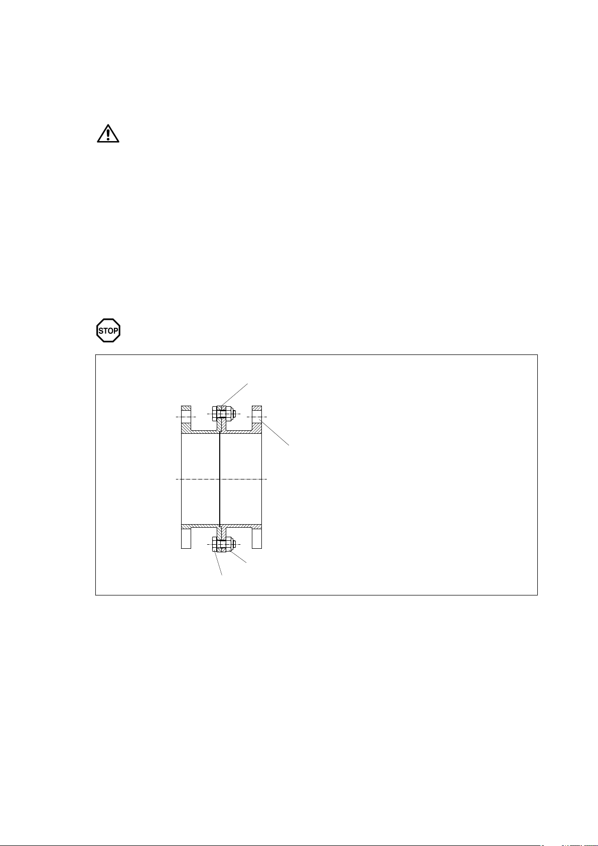
6.8 Split spacers
Split spacers are fitted together according to length and tightened handtight or delivered as single parts.
6.8.1 Fitting split spacers
• Before assembly the fitting holes and the contact surfaces of the coupling parts must be degreased.
Fitting holes and contact surfaces of the coupling parts must be absolutely clean and
greasefree.
Observe the manufacturer’s instructions for handling the solvent.
• The inner and outer "recess" (centering pin, figure 15) and the fitting bores as well as the contact faces
of the individual parts of the split spacer must be inspected for any damage and, if necessary, reworked.
• Before fitting the connecting bolts note any balancing marks (see fig. 15 and fig. 16). If the spacers are
unmarked, the halves must be fitted so that the fitting holes of the outer flanges are correctly aligned
(see fig. 15 and fig. 16).
• The connection of the "recess" or closefitting bolt must be joined accurately and carefully.
• The connecting bolts must be tightened crosswise and evenly with the specified tightening torque
(see table 5, "Tightening torques for connecting and tensioning bolts").
• Care must be taken that the "recess" connection is straight.
Failure to observe these instructions may result in impairing the proper function of the
coupling.
1
2
3
4
Fig. 15: Uspacer with "recess" (centering pin) (ARS6)
1 Marking on balanced spacer,
during fitting, the balance marks must be
one above the other
2 Fitting bore
3 All-steel locking nut to DIN 980 Form "V"
4 Hexagon bolt to ISO 4017 - 8.8
ARPEX 8704 en
Operating instructions 01/2019
23
Page 24
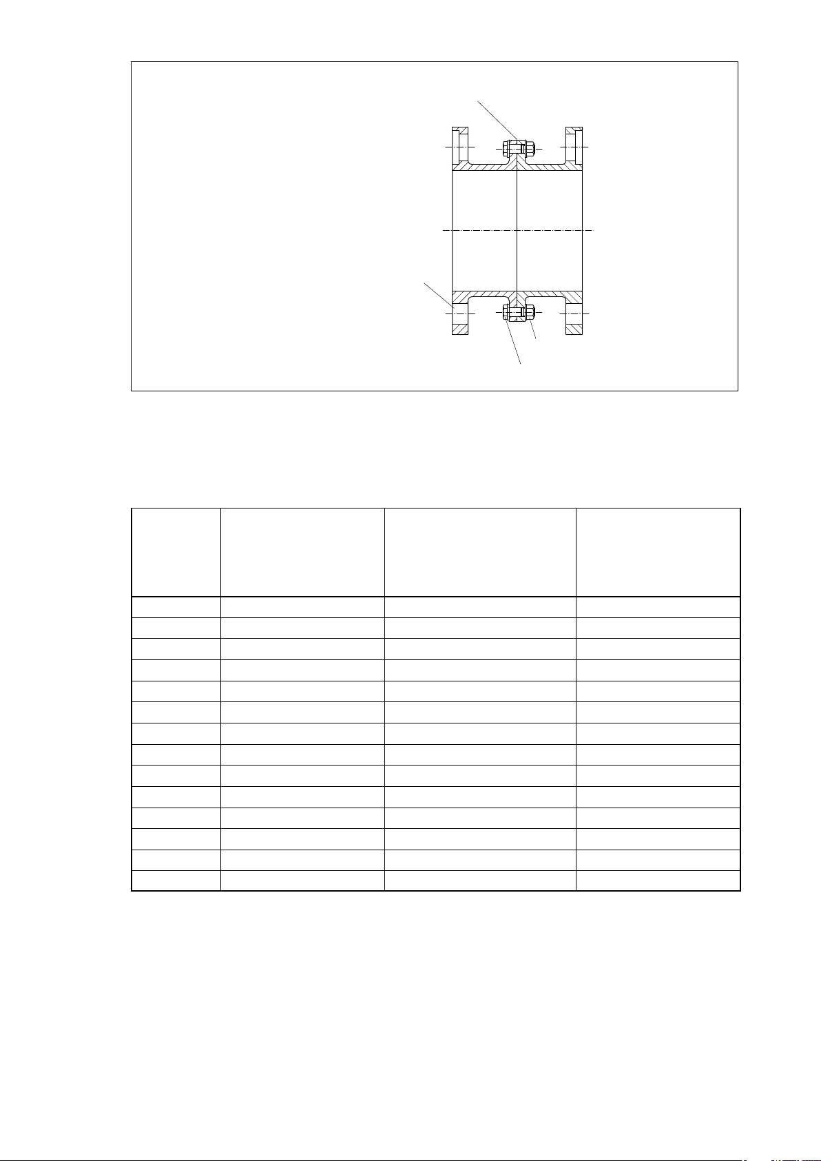
2
Fig. 16: Uspacer with closefitting bolts (ARC8)
1
3
4
1 Marking on balanced spacer Spacer,
during fitting, the balance marks must be
one above the other
2 Fitting bore
3 Flanged nut
4 Close-fitting bolt - 10.9
Table 5: Tightening torques for connecting and clamping bolts
Thread
Tightening torque T
Standard screw
+ standard nut to DIN
and ISO
Strength class 8.8 Strength class 8.8 Strength class 10.9
A
Tightening torque T
Standard screw
+ locking nut to DIN 980
See figure 15
A
Tightening torque T
Close-fitting bolt
Tensioning bolt
M 5 5 Nm 6 Nm 7 Nm
M 6 9 Nm 11 Nm 12 Nm
M 8 20 Nm 25 Nm 30 Nm
M 10 41 Nm 50 Nm 60 Nm
M 12 70 Nm 80 Nm 100 Nm
M 14 110 Nm 125 Nm 160 Nm
M 16 170 Nm 195 Nm 250 Nm
M 18 235 Nm 260 Nm 350 Nm
M 20 330 Nm 370 Nm 480 Nm
M 22 450 Nm 500 Nm 660 Nm
M 24 570 Nm 640 Nm 850 Nm
M 27 840 Nm 920 Nm 1200 Nm
M 30 1140 Nm 1200 Nm 1700 Nm
M 36 2000 Nm 2100 Nm 3100 Nm
A
+ collar nut
24
Operating instructions 01/2019
ARPEX 8704 en
Page 25
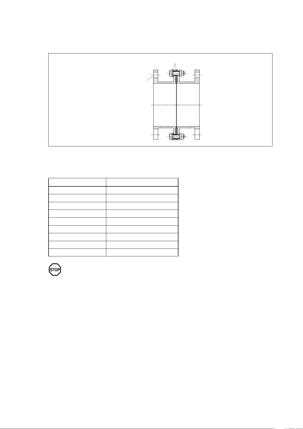
6.8.2 Fitting split spacers with creepcurrent insulation
Here the apply the same assembly instructions as those in item 6.8.1, however in the case of "U"spacers
with integrated creepcurrent insulation (see Fig. 17) the tightening torques in table 6, "Tightening torques
for connecting bolts with creepcurrent insulation" must always be adhered to.
2
Fig. 17: Split spacer with creepcurrent insulation
1 Creep-current insulation 2 Fitting bore
1
Table 6: Tightening torques for connecting bolts with creepcurrent insulation
Thread Tightening torque T
A
M 6 10 Nm
M 8 20 Nm
M 10 38 Nm
M 12 75 Nm
M 16 155 Nm
M 20 280 Nm
M 24 470 Nm
M 30 1000 Nm
M 36 1550 Nm
The tightening torques indicated in tables 5 and 6 apply only to untreated bolts which
are inserted (only lightly oiled) in the condition as delivered.
Other tightening values, which are additionally documented or must be enquired
about from the manufacturer, apply to coated or separately treated bolts.
ARPEX 8704 en
Operating instructions 01/2019
25
Page 26
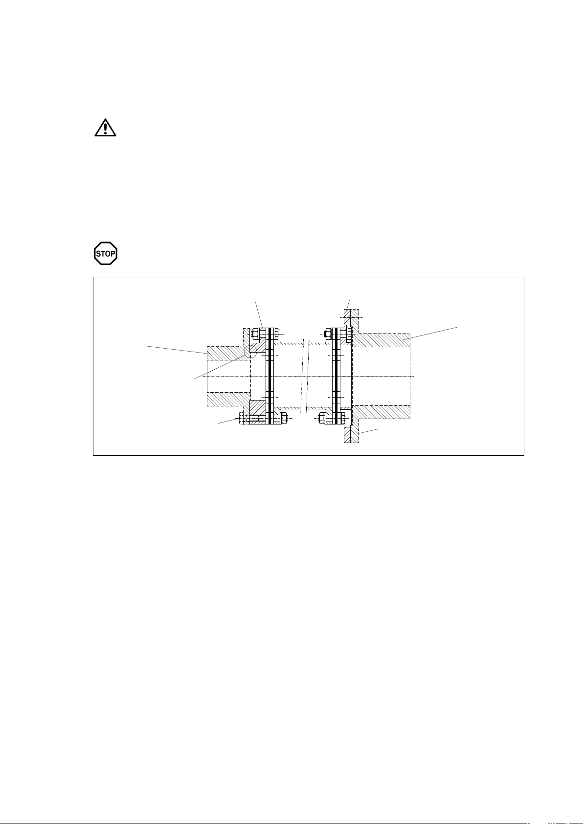
6.9 "C", "D" and "F" flange screw connection
"C", "D" and "F" flanges are delivered readyassembled as an individual part or with a spacer, as agreed.
6.9.1 Fitting
• Before fitting the coupling parts must be carefully cleaned with a suitable cleaning agent.
Observe the manufacturer’s instructions for handling the solvent.
• The "recess" (centering pin, Fig. 18) or fitting bores (Fig. 19) and the contact face of the "C", "D" and
"F" flange must be inspected for any damage and, if necessary, reworked.
• The connection of the "recess" or closefitting bolt must be joined accurately and carefully.
• The connecting bolts must be tightened crosswise and evenly with the specified tightening torque
(see table 5).
• Care must be taken that the "recess" connection is straight.
Failure to observe these instructions may result in impairing the proper function of the
coupling.
1
2
3
4
5
Fig. 18: "C" and "F" flange screw connection (example ARS)
1"C" flange
2"F" flange
3 Connection provided by the customer
5 Hexagon bolt to ISO 4017 - 8.8
6 Connection provided by the customer
7 Hexagon bolt to ISO 4017 - 8.8
4 "Recess" connection
6
7
26
Operating instructions 01/2019
ARPEX 8704 en
Page 27
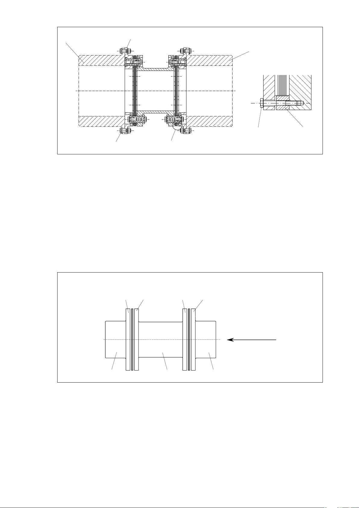
2
1
4
1)
5
67
3
Fig. 19: Fflange connection (example ARC)
1)
Detail "X"
1"F" flange
2 Connection provided by the customer
3 Close-fitting bolt with collar nut
4 Connection provided by the customer
6.10 Fitting of assemblybalanced couplings
On couplings which have been assemblybalanced each individual coupling component must be marked
on the outside diameter of the flange with a fourdigit number (Figure 20, "AAAA"). When assembling, care
must be taken that only coupling parts having the same numbers on the outside circumference of the flange
are bolted together. The coupling parts must be arranged so that the numbers are in line and can be read
from one direction (see figure 20). Only in this way will the balancing condition meet the requirements!
AAAA
AAAA
1)
5 Transport lock / mounting aid
6 Tensioning bolt
7 Fitting spacer
AAAA
AAAA
Fig. 20: Marking in case of assembly balancing
1 readable from here
2 Hub 1
ARPEX 8704 en
Operating instructions 01/2019
1
234
3 Spacer
4 Hub 2
27
Page 28
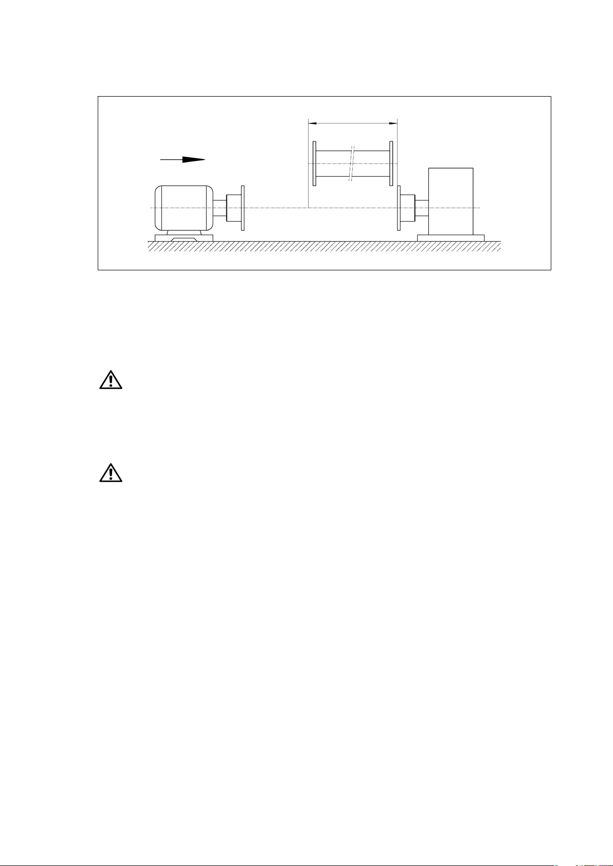
6.11 Pushing the units together
Set the shafts of the machines to be connected exactly the required shaft distance apart and align the
machines precisely (see figure 21).
Fig. 21: Aligning the units
1 Distance "SX" between shafts
6.11.1 Inserting spacer or intermediate unit
1
If necessary, using suitable lifting gear, insert spacer or intermediate unit between the flanges.
Notice, Danger of squeezing. Wear safety gloves.
If intermediate units with prefitted plate packs are used, they should not be demounted. The plate packs
are secured with transport locks (they are also used to facilitate assembly; see Detail "X" – figure 19).
After inserting the intermediate unit the transport locks must be removed, before the screw connections
of the flanges are tightened to the specified tightening torque.
Operation with the transport locks fitted is not permissible. Remove all transport
locks.
28
Operating instructions 01/2019
ARPEX 8704 en
Page 29

6.12 Fitting the plate packs
ARPEX plate packs are packed individually, when delivered. The delivery includes instructions for fitting
ARPEX plate packs in German. Instructions in other languages must be ordered separately.
ARPEX fitting instructions include all the necessary data and instructions for correctly fitting the plate
packs.
The tightening torques for the plate pack bolting should exclusively be taken from the related
actual assembly instructions!
Furthermore all necessary details for alignment of the units to be connected are documented.
Matching of all existing sets of fitting instructions with their series is shown in table 7.
The sets of fitting instructions set out below can be ordered from Flender or on the Internet (see back
cover).
Table 7: Matching of the individual series with their fitting instructions
Series Type Assembly instructions
ARS‐6
with close-fitting screw connection AN 4200
with conical bolting AN 4243
3-part (e.g. "NAN") with close-fitting screw connection AN 4224
ARP‐6
3-part (e.g. "NAN") with conical bolting AN 4256
ARP‐6
5-part (e.g. "MCECM") with close-fitting screw
connection
AN 4228
5-part (e.g. "MCECM") with conical bolting AN 4253
Standard version AN 4241
ARC‐6/8/10
Version with special conical bolting AN 4244
ARF‐6 Standard version AN 4233
with close-fitting screw connection AN 4239
ARW‐4/6
with conical bolting AN 4254
with close-fitting screw connection AN 4213
ARH‐8
with conical bolting AN 4246
ARPEX 8704 en
Operating instructions 01/2019
29
Page 30
7. Startup
Observe the instructions in section 3, "Safety instructions"!
7.1 Procedure before startup
Before startup the screw connections must be checked and, if necessary, retightened. The alignment
and the distance dimension "S
checked and, if necessary, adjusted.
Coupling types with prefitted plate packs must be checked before startup to ensure that the transport
locks (see detail "X" – Figure 19) have been completely removed.
Then finally fit the coupling guard to prevent unintentional contact.
For the use in potentially explosive environments the protective equipment must
comply at least with type of protection IP2X.
Failure to observe these instructions may result in breakage of the coupling.
Danger to life from flying fragments.
A damaged coupling becomes an explosion hazard. Operating the coupling with
damaged coupling parts is not permitted in potentially explosive environments in
accordance with Directive 2014/34/EU.
" (see tables in seriesspecific assembly instructions) must also be
1
8. Operation
Observe the instructions in section 3, "Safety instructions"!
8.1 General operating data
During operation of the coupling watch for:
• Changes in running noise
• Sudden vibrations
If any malfunctions are noticed during operation, the drive assembly must be switched
off at once. The cause of the fault must be determined, using the fault table in section 9.
The troubleshooting table contains a list of possible faults, their causes and
suggested remedies.
If the cause cannot be identified or the unit repaired with the facilities available, you
are advised to contact one of the Flender customerservice offices for specialist
assistance (see section 2).
30
Operating instructions 01/2019
ARPEX 8704 en
Page 31
9. Faults, causes and remedy
Observe the instructions in section 3, "Safety instructions"!
9.1 General
The following irregularities can serve as a guide for fault tracing.
Where the system is a complex one, all component units must be included when tracing faults.
The coupling must run with little noise and vibration in all operating phases. Irregular behaviour must be
treated as a fault requiring immediate remedy.
Flender will not be bound by the terms of the guarantee or warranty or otherwise be
responsible in cases of improper use of the coupling, modifications on the coupling
carried out without the agreement of Flender, or use of spare parts not supplied by
Flender.
When remedying faults and malfunctions, the coupling must always be taken out of
service. Secure the drive unit to prevent it from being started up unintentionally.
A notice should be attached to the ON switch stating clearly that work is in progress.
We also refer to the relevant accident prevention regulations at the place of
installation.
9.2 Possible faults
Table 8: Faults, causes and remedy
Faults Causes Remedy
Sudden changes in the noise
level and/or sudden
vibrations.
Operating the coupling with broken ARPEX plate packs is not permitted under
Directive 2014/34/EU. A correct torque transmission is no longer guaranteed in such
case. Perform a visual check of the ARPEX coupling as described in section 10.
A damaged coupling becomes an explosion hazard. Operating the coupling with
damaged coupling parts is not permitted in potentially explosive environments in
accordance with Directive 2014/34/EU.
Change in alignment. Stop the installation.
If necessary, rectify any cause of the
changes in alignment (e.g. by fastening loose
foundation bolts).
Check wear; procedure as described in
section 10.
Plate breakage, torque
transmission via close-fitting
bolts / conical bolting
Stop the installation.
Demount coupling and remove remains of
pack.
Check and replace damaged coupling parts.
Check and, if necessary, adjust alignment
(see section 6).
ARPEX 8704 en
Operating instructions 01/2019
31
Page 32

9.3 Improper use
Experience has shown that the following faults can result in incorrect use of the ARPEX coupling. In
addition to observing the other instructions in this manual, care must therefore be taken to avoid these
faults.
Directive 2014/34/EU requires the manufacturer and user to exercise especial care.
Failure to observe these instructions may result in breakage of the coupling.
Danger to life from flying fragments.
Through incorrect use the coupling may become an explosion hazard.
Incorrect use of the ARPEX coupling can result in damage to the coupling.
Coupling damage may result in stoppage of the drive and the entire plant.
9.3.1 Possible faults when selecting the coupling and/or coupling size
• Important information for describing the drive and the environment are not communicated.
• System torque too high.
• System speed too high.
• Application factor not correctly selected.
• Chemically aggressive environment is not taken into consideration.
• The temperature in the direct vicinity of the coupling is beyond the permissible range.
• Machining of a finished bore with incorrect diameter or incorrect fit assignment (see section 6).
• The transmission capacity of the shafthub connection is not appropriate to the operating conditions.
9.3.2 Possible faults when installing the coupling
• Components with transport or other damage are being fitted.
• When fitting coupling parts in a heated condition, these components are being excessively heated.
• The shaft diameter is beyond the specified tolerance range.
• Coupling parts are interchanged during fitting work.
• Specified tightening torques and/or angles are not being adhered to.
• Alignment and/or shaftmisalignment values do not match the specifications in the assembly and/or
operating instructions.
• The coupled machines are not correctly fastened to the foundation, and as a result shifting of the
machines e.g. through loosening of the foundationscrew connection is causing excessive
displacement of the coupling parts.
• ARPEX plate packes are not fitted correctly (see seriesspecific assembly instructions).
• The coupling protection used is not suitable for operation within the meaning of the
explosionprotection requirements and/or in accordance with Directive 2014/34/EU.
32
• Operating conditions are being changed without authorisation.
ARPEX 8704 en
Operating instructions 01/2019
Page 33
9.3.3 Possible faults in maintenance
• Maintenance intervals are not being adhered to.
• No genuine ARPEX plate packs are being used.
• Damaged ARPEX plate packs are being used.
• ARPEX plate packs are being used which do not meet the technical specification for the application.
• Leakage in the vicinity of the coupling is not being identified and as a result chemically aggressive
media are damaging the coupling.
10. Maintenance and repair
Observe the instructions in section 3, "Safety instructions"!
All work on the coupling must be carried out only when it is at a standstill.
The drive unit must be secured against being switched on accidentally (e.g. by locking
the key switch or removing the fuses from the power supply). A notice should be
attached to the ON switch stating clearly that work is in progress.
We also refer to the relevant accident prevention regulations at the place of
installation.
10.1 General
ARPEX couplings do not require maintenance; however, they should be visually inspected during
regular system maintenance inspections at least once a year. Especial attention should be given to the
condition of the plate packs. If individual plates or several plates are broken, the plate pack affected must
be replaced (see item 10.2).
No further maintenance work is necessary.
If the above specified maintenance instructions are not adhered to, a correct operation
of the coupling within the meaning of Directive 2014/34/EU can no longer be
guaranteed.
10.2 Replacing plate packs
Only original ARPEX plate packs must be used for replacement in order to guarantee troublefree torque
transmission and faultfree operation.
Normally, the plate packs can be replaced without moving the coupled machines. Exceptions
are combinations with socalled "B" hubs (hubs which for reasons of space are fitted the other
way round and so project into the spacer) and special solutions.
For refitting, the instructions in section 6, "Assembly", and section 7, "Startup", must be carefully
observed!
ARPEX 8704 en
Operating instructions 01/2019
33
Page 34

11. Spare parts, customer service
11.1 Spareparts stockage
By stocking the most important spare parts on site you can ensure that the coupling is ready for use.
To order spare parts, refer to the spareparts list.
We guarantee only the original spare parts supplied by us. Nongenuine spare parts
have not been tested or approved by us. They may alter technical characteristics of
the coupling, thereby posing an active and/or passive risk to safety. Flender will
assume no liability or guarantee for damage caused by nongenuine spare parts not
supplied by Flender. The same applies to any accessories not supplied by Flender.
Please note that certain components often have special production and supply specifications and that we
supply you with spare parts which comply fully with the current state of technical development as well as
current legislation.
When ordering spare parts, always state the following:
─ Quantity
─ Designation
─ Size
─ Number of the coupling drawing
─ Position of the spare part in the spareparts list
11.2 Addresses for ordering spare parts and customer service
When ordering spare parts or requesting a service specialist, please contact Flender first (see section 2,
"General notes").
34
Operating instructions 01/2019
ARPEX 8704 en
Page 35

12. Declarations
12.1 EU declaration of conformity
EU declaration of conformity
Product:
FLENDER
Couplings
Series
Name and address of the manufacturer:
Flender GmbH
Schlavenhorst 100
46395 Bocholt
Deutschland – Germany
This declaration of conformity is issued under the sole responsibility of the manufacturer.
Object of the declaration is the product specified above.
The object of the declaration described above is in conformity with the relevant harmonisation legislation of the
Union:
– Directive 2014/34/EU Official Journal L 96, 29.3.2014, pages 309-356
Harmonised standards or other technical specifications, on which the declaration of conformity is based:
EN 1127-1 : 2011
EN ISO 80079-36 : 2016
EN ISO 80079-37 : 2016
EN ISO 80079-38 : 2017
The notified body, DEKRA EXAM GmbH, code number 0158, has received the technical documentation.
Signed for and on behalf of:
Flender GmbH
ARPEX®
ARS-6, ARP-6, ARH-8, ARC-6/8/10, ARW-4/6, ARF-6
Bocholt,
2019‐01‐01
Dr. Tim Sadek, Vice President, Applications Couplings
ARPEX 8704 en
Operating instructions 01/2019
35
Page 36

FLENDER COUPLINGS
- - - - - - - - - - - - - - - - - - - - - - - - - - - - - - - - - - - - - - - - - - - - - - - - - - - - - - - - - - - - - -
ARPEX
Operating instructions 8704 en
Edition 01/2019
- - - - - - - - - - - - - - - - - - - - - - - - - - - - - - - - - - - - - - - - - - - - - - - - - - - - - - - - - - - - - -
Flender GmbH
Alfred-Flender-Straße 77
46395 Bocholt
GERMANY
flender.com
 Loading...