

Page 1

FLENDER COUPLINGS
ART, ARE
Operating instructions 8706 en
Edition 10/2017
ARPEX
- - - - - - - - - - - - - - - - - - - - - - - - - - - - - - - - - - - - - - - - - - - - - - - - - - - - - - - - - - - - - -
- - - - - - - - - - - - - - - - - - - - - - - - - - - - - - - - - - - - - - - - - - - - - - - - - - - - - - - - - - - - - -
- - - - - - - - - - - - - - - - - - - - - - - - - - - - - - - - - - - - - - - - - - - - - - - - - - - - - - - - - - - - - -
- - - - - - - - - - - - - - - - - - - - - - - - - - - - - - - - - - - - - - - - - - - - - - - - - - - - - - - - - - - - - -
flender.com
Page 2

Page 3
FLENDER COUPLINGS
Operating instructions
ARPEX
8706 en
ART, ARE
Edition 10/2017
Translation of the original operating instructions
T
echnical data
Spare parts,
customer service
Maintenance
and repair
Faults, causes
and remedy
Operation
Start-up
Fitting
T
echnical description
T
ransport and storage
Safety instructions
General notes
Declarations
1
12
11
10
9
8
7
6
5
4
3
2
Page 4
Flender GmbH
Alfred-Flender-Straße 77
46395 Bocholt
GERMANY
Document number: 8706 en
10/2017 Subject to alterations
Copyright © Flender GmbH 2017
All rights reserved
Legal notes
Warning note concept
This manual comprises notes which must be observed for your personal safety and for preventing material
damage. Notes for your personal safety are marked with a warning triangle, those only for preventing material
damage appear without a warning triangle. Depending on the level of hazard, the warning notes are shown in
reverse order of seriousness, as follows.
DANGER
means, that death or serious injury will result, if the appropriate preventive action is not taken.
WARNING
means that death or serious injury may result, if the appropriate preventive action is not taken.
CAUTION
means that a slight injury may result, if the appropriate preventive action is not taken.
NOTICE
means that material damage may result, if the appropriate preventive action is not taken.
Where there is more than one hazard level, the warning note for whichever hazard is the most serious is always
used. If in a warning note a warning triangle is used to warn of possible personal injury, a warning of material
damage may be added to the same warning note.
Qualified personnel
The product/system to which this documentation relates may be handled only by persons qualified for the work
concerned and in accordance with the documentation relating to the work concerned, particularly the safety and
warning notes contained in those documents.
Qualified personnel must be specially trained and have the experience necessary to recognise risks associated
with these products and to avoid possible hazards.
Proper use of Flender products
Observe also the following:
WARNING
Flender products must be used only for the applications provided for in the catalogue and the relevant technical
documentation. If products and components of other makes are used, they must be recommended or approved
by Flender. The faultfree, safe operation of the products calls for proper transport, proper storage, erection,
assembly, installation, startup, operation and maintenance. The permissible ambient conditions must be
adhered to. Notes in the relevant documentations must be observed.
Trade marks
All designations to which the registered industrial property mark ® is appended are registered trademarks of
Flender GmbH. Other designations used in this document may be trademarks the use of which by third parties
for their own purposes may infringe holders’ rights.
Exclusion of liability
We have checked the content of the document for compliance with the hard and software described.
Nevertheless, variances may occur, and so we can offer no warranty for complete agreement. The information
given in this document is regularly checked, and any necessary corrections are included in subsequent editions.
Page 5
Flender GmbH
Alfred-Flender-Straße 77
46395 Bocholt
GERMANY
Document number: 8706 en
10/2017 Subject to alterations
Copyright © Flender GmbH 2017
All rights reserved
Note on the EC Machinery Directive 2006/42/EC
The couplings described here are “components” in accordance with the Machinery Directive and do not require
a declaration of incorporation.
Symbols in these operating instructions
This symbol additionally indicates an imminent risk of explosion in the meaning of Directive 2014/34/EU.
This symbol additionally indicates an imminent risk of burns due to hot surfaces in the meaning of standard "DIN
EN ISO 13732-1".
Page 6

6
ARPEX 8706 en
Operating instructions 10/2017
Contents
1. Technical data 8.....................................................
2. General notes 9.....................................................
2.1 Introduction 9........................................................................
2.2 Copyright 9..........................................................................
3. Safety instructions 10.................................................
3.1 Obligations of the user 10...............................................................
4. Transport and storage 12.............................................
4.1 Scope of supply 12....................................................................
4.2 Transport 12..........................................................................
4.3 Storage of the coupling 13..............................................................
5. Technical description 14..............................................
5.1 General description 14.................................................................
5.2 Coupling types and component arrangement 16............................................
5.2.1 Standard types 16.....................................................................
5.2.2 Special types 19.......................................................................
5.3 Marking of the coupling parts for use in potentially explosive areas 21.........................
5.4 Operating conditions 21................................................................
5.5 Condition on delivery 22................................................................
5.5.1 Type BVB 22..........................................................................
5.5.2 Type XVX 23..........................................................................
5.5.3 Type MHM 24.........................................................................
5.5.4 Type with "H" module 25................................................................
5.5.5 Special types 26.......................................................................
6. Fitting 27.............................................................
6.1 General information on fitting 27.........................................................
6.2 Preparation for fitting 28................................................................
6.3 Screw connection of flange 28...........................................................
6.4 Fitting the coupling parts 29.............................................................
6.4.1 Fitting "B", "X" modules and "M"hubs 29..................................................
6.4.2 Fitting "F" flanges 31...................................................................
6.4.3 Fitting "F" and "D" modules 31...........................................................
6.5 Test run of the customer’s shaft with fitted coupling parts 32.................................
6.6 Compensation of the flange or shaft distance "DBSE" 32....................................
6.7 Fitting of assemblybalanced couplings 34................................................
6.8 Fitting the intermediate unit 35...........................................................
6.8.1 Procedure applying to modules with distance bush 35.......................................
6.8.2 Procedure applying to modules with threaded bush 36......................................
6.8.3 Fitting the intermediate unit 37...........................................................
Page 7

7
ARPEX 8706 en
Operating instructions 10/2017
6.9 Alignment 39..........................................................................
6.9.1 Aligning with distance bush 39...........................................................
6.9.2 Aligning with threaded bush 41..........................................................
6.10 Test run of the customer’s shaft with weight simulators 42...................................
6.10.1 Definition of weight simulators for the test run 42...........................................
6.10.2 Fastening of coupling modules for the test run 43...........................................
6.10.3 Test run of fitted coupling parts with dummy flange 44.......................................
6.10.4 Test run of fitted dummies 46............................................................
6.11 Demounting the intermediate unit 48......................................................
6.11.1 Procedure applying to modules with distance bush 48.......................................
6.11.2 Procedure applying to modules with threaded bush 50......................................
6.11.3 Demounting the fitted coupling modules or components 52..................................
7. Startup 53...........................................................
7.1 Procedure before startup 53............................................................
8. Operation 55.........................................................
8.1 General operating data 55..............................................................
9. Faults, causes and remedy 56.........................................
9.1 General 56............................................................................
9.2 Possible faults 58......................................................................
9.3 Incorrect use 59.......................................................................
9.3.1 Possible faults when selecting the coupling and/or coupling size 59...........................
9.3.2 Possible faults when fitting the coupling 60................................................
9.3.3 Possible faults in the maintenance of the plant 60...........................................
10. Maintenance and repair 61............................................
10.1 General 61............................................................................
10.2 Replacing plate packs 61...............................................................
10.3 Replacing screw connections of the flanges 61.............................................
11. Spare parts, customerservice 62......................................
11.1 Spareparts and customerservice addresses 62...........................................
12. Declarations 63.......................................................
12.1 EU declaration of conformity 63..........................................................
Page 8
8
ARPEX 8706 en
Operating instructions 10/2017
1. Technical data
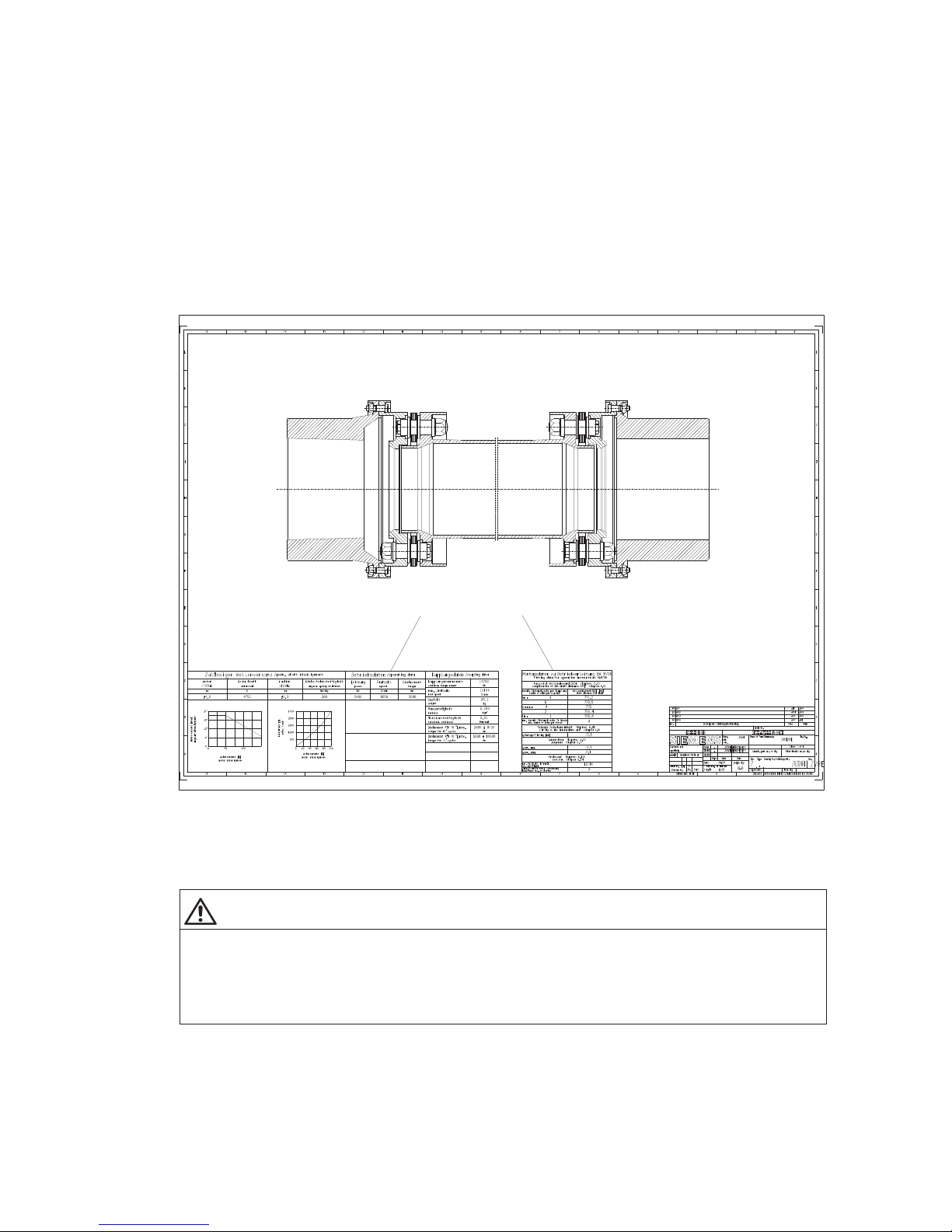
Enclosed with the coupling delivery and the documentation is an orderspecific dimensioned drawing
showing all the technical data necessary for fitting (see Fitting data field in figure 1). The coupling can be
fitted with the aid of these instructions only in conjunction with the orderspecific drawing of the
coupling.
The technical data to the ARPEX couplings listed in these instructions are documented on the
orderspecific drawing of the coupling (see "Operating and Coupling Data" fields in figure 1) and in the
current product catalogue and are available on request or can be accessed at any time on the Internet (see
cover at back).
Because of customerspecific adaptations the standard design is frequently deviated from. The technical
data on the orderspecific drawing of the couplings should always be followed before the data in
the current product catalogue, therefore.
2
1
Fig. 1: Orderspecific drawing of the coupling
1 Operating and coupling data 2 Fitting data
These data together with the contractual agreements on the coupling determine the limits of its proper use.
WARNING
Risk of serious injury through flying fragments
Risk of serious injury through flying fragments and/or risk of damage to the coupling.
The coupling must be designed with an application factor appropriate to the application. In the event of
a change in operating conditions (output, speed, prime mover and driven machine) the design must
always be checked.
Page 9

9
ARPEX 8706 en
Operating instructions 10/2017
2. General notes
2.1 Introduction
These instructions are an integral part of the delivery of the coupling and must be kept in its vicinity for
reference at all times.
WARNING
Risk of serious injury through flying fragments
Risk of serious injury through flying fragments and/or risk of damage to the coupling.
– All persons carrying out work on the coupling must have read and understood these instructions and
must adhere to them.
– Any changes on the part of the user are not permitted. This applies equally to safety features designed
to prevent accidental contact.
– The coupling is designed only for the application specified in the order. Other operating conditions are
regarded as incorrect.
The "FLENDER coupling" described in these instructions has been developed for stationary use in
general engineering applications. The coupling serves to transmit power (torque and speed) between two
shafts or flanges connected by this coupling.
The coupling has been manufactured in accordance with the state of the art and is delivered in a condition
for safe and reliable use.
The coupling complies with the requirements in Directive 2014/34/EU.
The coupling must be used and operated strictly in accordance with the conditions laid down in the contract
governing performance and supply.
The coupling described in these instructions reflects the state of technical development at the time these
instructions went to print.
In the interest of technical progress we reserve the right to make changes to the individual assemblies and
accessories which we regard as necessary to preserve their essential characteristics and improve their
efficiency and safety.
2.2 Copyright
The copyright to these operating instructions is held by Flender.
These instructions must not be wholly or partly reproduced for competitive purposes, used in any
unauthorised way or made available to third parties without our agreement.
Technical enquiries should be addressed to the following factory or to one of our customer services:
Flender GmbH
Schlavenhorst 100
46395 Bocholt
Tel.: +49 (0)2871 / 92-0
Fax: +49 (0)2871 / 92-2596
Page 10
10
ARPEX 8706 en
Operating instructions 10/2017
3. Safety instructions
Observe the information in section 2, "General notes".
DANGER
Danger of explosion
Risk of explosion when operating in potentially explosive areas.
Incorrect changes made to the coupling will create ignition sources.
Any changes on the part of the user are not permitted. This applies equally to safety features designed
to prevent accidental contact. For the use in potentially explosive environments the protective
equipment must comply at least with type of protection IP2X.
DANGER
Danger of explosion
Risk of explosion when using unsuitable components in potentially explosive areas.
Use the coupling only for the approved zones and equipment groups. In case of doubt, contact Flender.
DANGER
Danger of explosion
Risk of explosion when operating in potentially explosive areas.
Damaged coupling modules and coupling parts are potential explosion hazards.
Use only undamaged coupling components. Operating the coupling with damaged coupling parts is not
permitted in potentially explosive environments in accordance with Directive 2014/34/EU.
3.1 Obligations of the user
• The operator must ensure that everyone carrying out work on the coupling has read and understood
these instructions and is adhering to them in every point in order to:
─ avoid injury or damage,
─ ensure the safety and reliability of the coupling,
─ avoid disruptions and environmental damage through incorrect use.
• During transport, assembly, fitting, demounting, and maintenance of the unit, the relevant safety and
environmental regulations must be complied with.
• The coupling may only be maintained and/or repaired by persons qualified for the work concerned
(see "Qualified personnel" on page 3 of this manual).
• The outside of the coupling must not be cleaned with highpressure cleaning equipment.
• All work must be carried out with great care and with due regard to safety.
Page 11
11
ARPEX 8706 en
Operating instructions 10/2017
DANGER
Danger to life through switchedon installation
Risk of being caught or drawn in by rotating and/or movable parts.
To carry out work on the coupling, the system must always be stopped. The drive unit must be secured
against being switched on accidentally (e.g. by locking the key switch or removing the fuses from the
power supply).
A notice should be attached to the ON switch stating clearly that work is in progress.
At the same time the complete installation must be without load, so that no danger occurs during
demounting operations.
WARNING
Risk of serious injury through rotating components
Risk of serious injury through contact with rotating components.
The coupling must be fitted with suitable safeguards to prevent any contact. The operation of the
coupling must not be impaired by the safeguard. This also applies to test runs and when checking the
direction of rotation.
WARNING
Risk of serious injury through flying fragments
Risk of serious injury through flying fragments and/or risk of damage to the coupling.
If any malfunctions or changes are noticed during operation, the drive assembly must be switched off
at once.
Note
If the coupling is fitted in plant or equipment, the manufacturer of such plant or equipment must ensure
that the contents of the present instructions are incorporated in his own instructions.
WARNING
Risk of serious injury through flying fragments
Risk of serious injury through flying fragments and/or risk of damage to the coupling through use of
defective spare parts.
Flender guarantees only the genuine spare parts supplied by Flender.
Nongenuine spare parts have not been tested or approved by Flender. Nongenuine spare parts may
alter technical characteristics of the coupling, thereby posing an active or passive risk to safety.
Flender will assume no liability or guarantee for damage caused by spare parts not supplied by Flender.
The same applies to any accessories not supplied by Flender.
Page 12
12
ARPEX 8706 en
Operating instructions 10/2017
4. Transport and storage
Observe the instructions in section 3, "Safety instructions"!
4.1 Scope of supply
The products supplied are listed in the dispatch papers. Check on receipt to ensure that all the products
listed have actually been delivered. Parts damaged and/or missing parts must be reported to Flender in
writing immediately.
4.2 Transport
Different forms of packaging may be used depending on the size of the coupling and method of transport.
Unless otherwise agreed, the packaging complies with the HPE Packaging Guidelines.
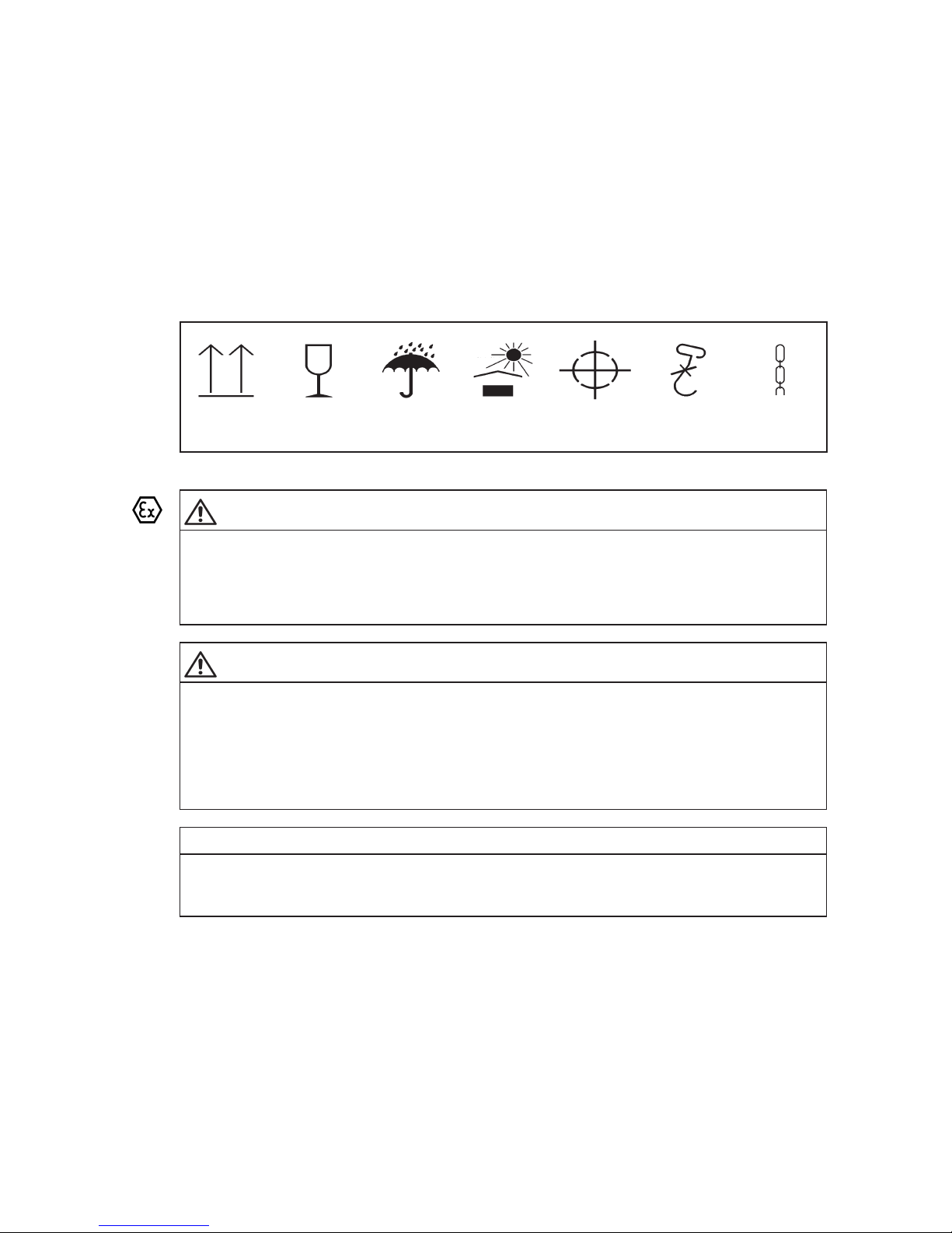
The following symbols with their meanings are applied to the packaging and must be observed:
Top Fragile Keep dry Keep cool Centre of
gravity
Use no hand
hook
Attach
here
Fig. 2: Transport symbols
DANGER
Danger of explosion
Risk of explosion when operating in potentially explosive areas.
Damaged coupling modules and coupling parts are potential explosion hazards.
Use only undamaged coupling components. Operating the coupling with damaged coupling parts is not
permitted in potentially explosive environments in accordance with Directive 2014/34/EU.
WARNING
Serious injury
Risk of serious injury through falling components or quenching.
Damage to coupling parts when using unsuitable transport equipment.
When handling these products, use only lifting and handling equipment of sufficient loadbearing
capacity.
Transport of the coupling must be carried out so as to avoid personal damage and damage to the
coupling.
NOTICE
Material damage
Risk of material damage if not observing the packaging symbols.
The symbols marked on the packing must be observed.
Page 13

13
ARPEX 8706 en
Operating instructions 10/2017
4.3 Storage of the coupling
The coupling is delivered in a preserved condition and can be stored in a covered, dry place for up to
6 months. If the unit is to be stored for a longer period, it should be treated with a longterm preservative
agent (Flender must be consulted).
Correctly stored couplings retain their properties unchanged.
NOTICE
Risk of damage to the coupling through improper storage
Impairment of the physical properties of the coupling and/or coupling parts.
The storage area must be dry (air humidity less than 65 %) and free from dust. Ensure that no
condensation occurs. Do not store with aggressive chemicals, acids, alkalis, etc.
If the coupling contains elastomer components, no ozonegenerating equipment of any kind, such as
fluorescent light sources, mercury vapour lamps or hightension electrical equipment, must be allowed
into the storage areas.
Storage of the coupling on suitable aids or in suitable containers.
Page 14
14
ARPEX 8706 en
Operating instructions 10/2017
5. Technical description
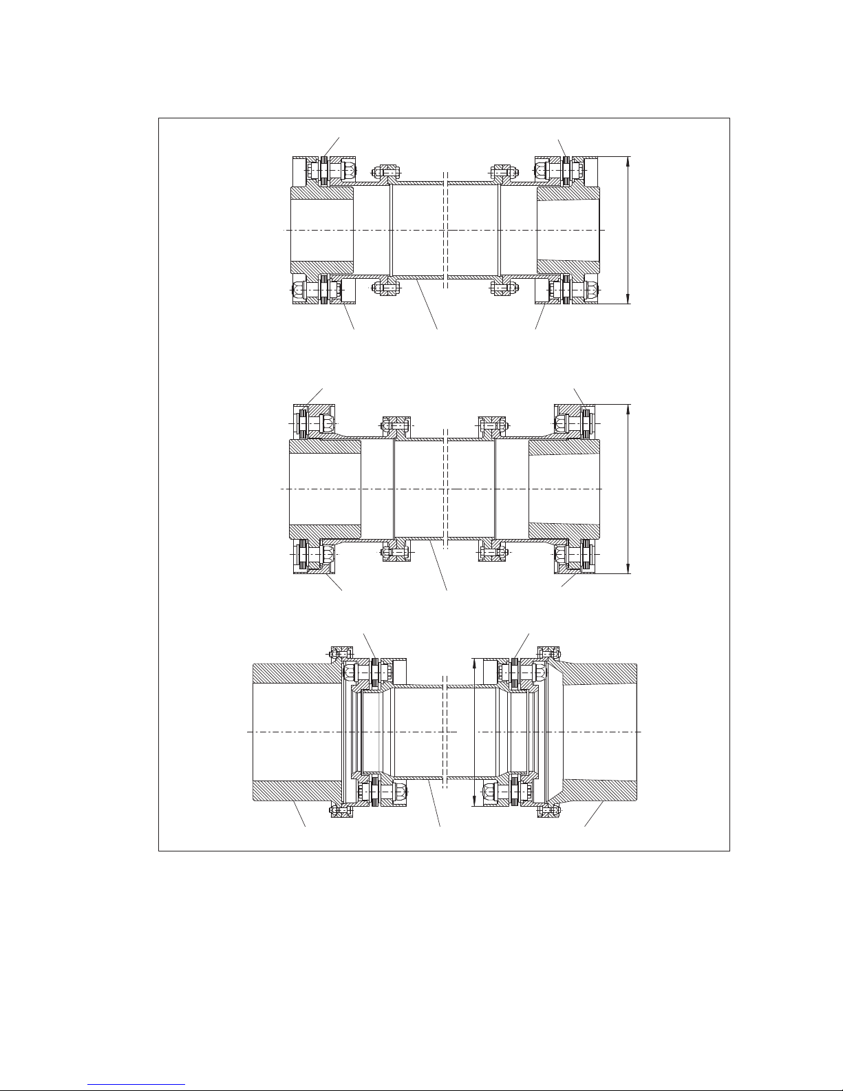
5.1 General description
1
1
2
3
2
øDA
XVX
11
4
3
4
øDA
MHM
1
1
6
5
6
øDA
BVB
Fig. 3: Types BVB, XVX and MHM
1 Plate pack 2 "B" module
3"V"-spacer 4 "X" module
5"H" module 6 "M" hub
Page 15
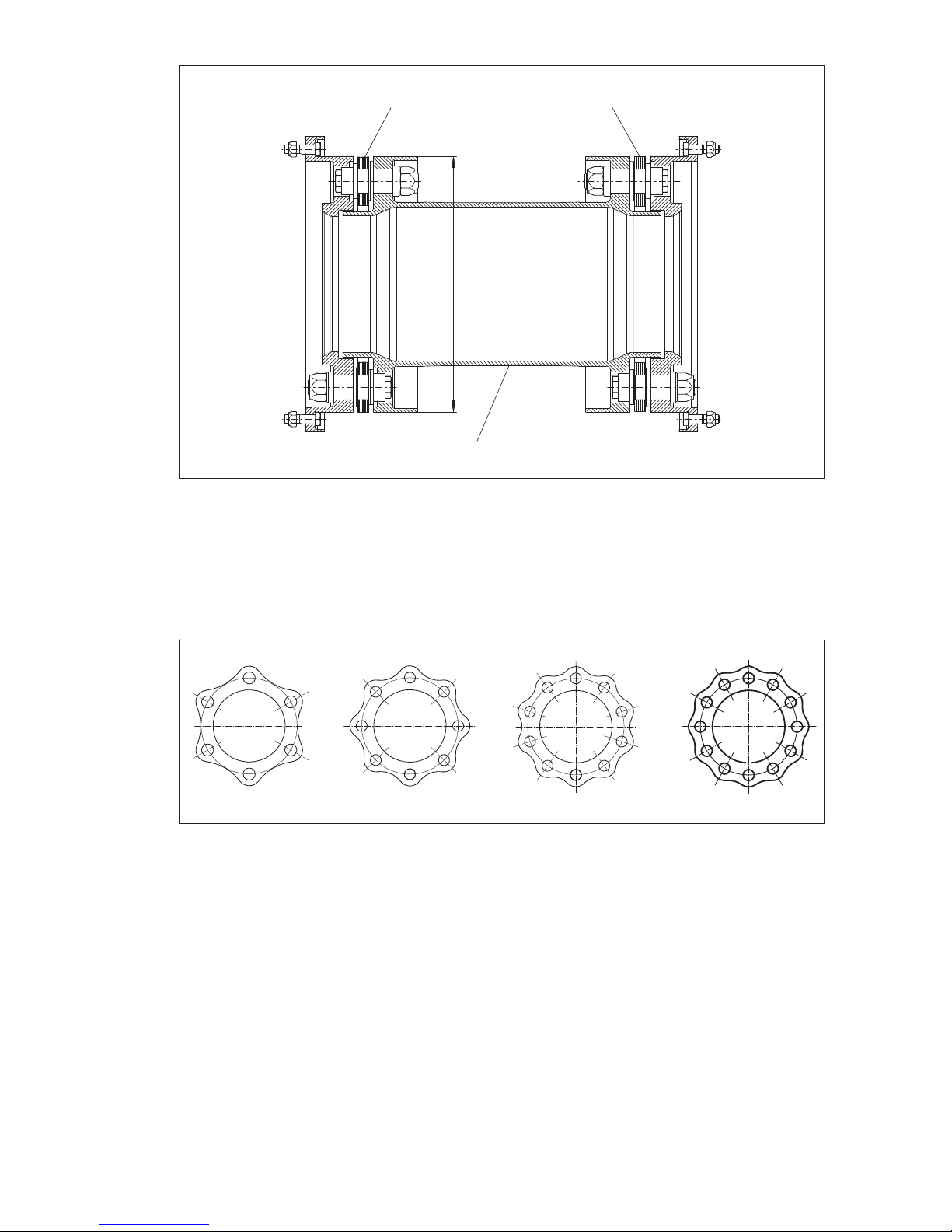
15
ARPEX 8706 en
Operating instructions 10/2017
1
1
øDA
2
Fig. 4: Type with "H" module
1 Plate pack 2 "H" module
ARPEXturbo couplings are allsteel couplings and can be supplied, inter alia, in the types shown in
figures 3 and 4. The plate packs are arranged in the fitted coupling modules between the flanges of the
coupling parts and bolted to them alternately. The ARPEX coupling is torsionresistant and transmits the
torque without circumferential backlash. In axial and radial direction the coupling is however still flexible
and can absorb axial, radial and angular misalignment of the coupled units.
132
4
Fig. 5: Designs of the plates
1 6-sided plate ART/ARE-6 2 8-sided plate ART/ARE-8
3 10-sided plate ART/ARE-10 4 12-sided plate ART/ARE-12,
special version
The size designation of the coupling indicates the outside flange diameter DA (see fig. 3 and/or fig. 4) of
the coupling in mm. Attached item 6, 8, 10 or 12 (special version) specifies the number of
screwconnection points on the plate pack (see figure 5). This information is prefixed by a letter
combination specifying the component parts of the coupling.
Example: ART8 BVB 2208
Coupling with "B" module (B) "V"spacer (V) "B" module (B) of size 2208
from the ART8 series
Page 16
16
ARPEX 8706 en
Operating instructions 10/2017
5.2 Coupling types and component arrangement
All coupling types of the ART/ARE series are assembled from individual components (e.g. "M" hubs
and/or "F" flanges) and from coupling modules (e.g. "B" module and/or"H" module), which contain the
plate packs. The coupling components and coupling modules are joined together with flange screw
connections. Items 5.2.1 and 5.2.2 show both standard types and possible special types.
Note
The exact arrangement of the coupling components, coupling modules, screw connections of the
flanges and further accessories such as shims can be found on the orderspecific drawing of the
coupling.
5.2.1 Standard types
In the following figures 6, 7, 8 and 9 the four standard types, BVB, XVX, MHM, and the "H" module of
the ART/ARE series are shown.
*)
B
B
V
1
12
2
3
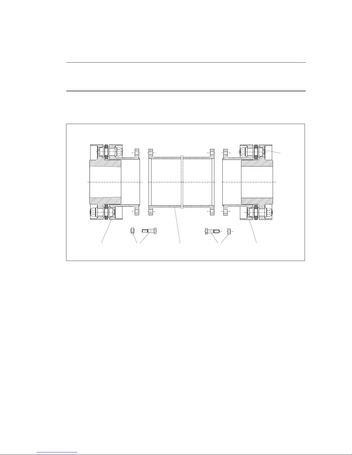
Fig. 6: Standard type BVB
1"B" module 2 Screw connection of flange
3"V"‐spacer (intermediate unit)
*)The plate packs must not be demounted or retightened!
Page 17
17
ARPEX 8706 en
Operating instructions 10/2017
13
2
1
2
*)
X
V
X
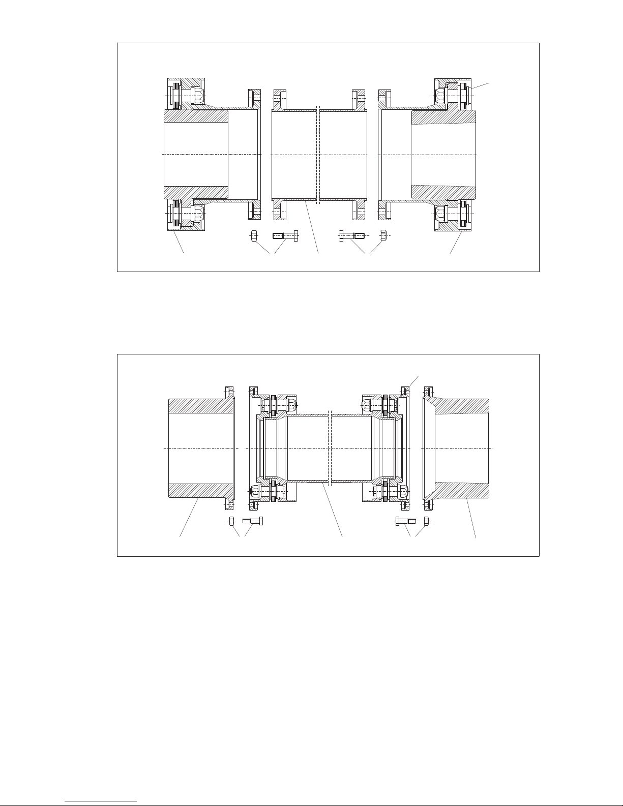
Fig. 7: Standard type XVX
1"X" module 2 Screw connection of flange
3"V"‐spacer (intermediate unit)
*)The plate packs must not be demounted or retightened!
*)
M
MH
1
1
2
2
3
Fig. 8: Standard type MHM
1"M" hub 2 Screw connection of flange
3"H" module (intermediate unit)
*)The plate packs must not be demounted or retightened!
Page 18
18
ARPEX 8706 en
Operating instructions 10/2017
H
2
1
2
*)
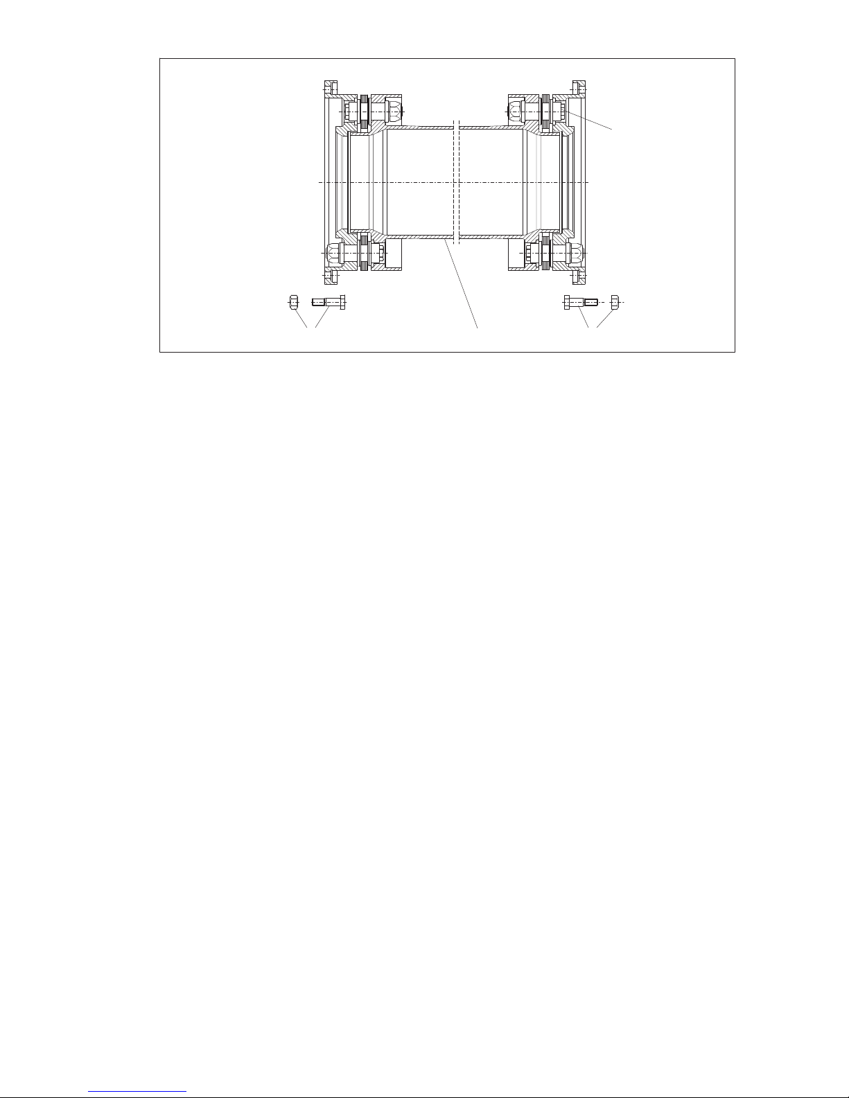
Fig. 9: Standard type with "H" module
1"H" module (intermediate unit) 2 Screw connection of flange
*)The plate packs must not be demounted or retightened!
Page 19
19
ARPEX 8706 en
Operating instructions 10/2017
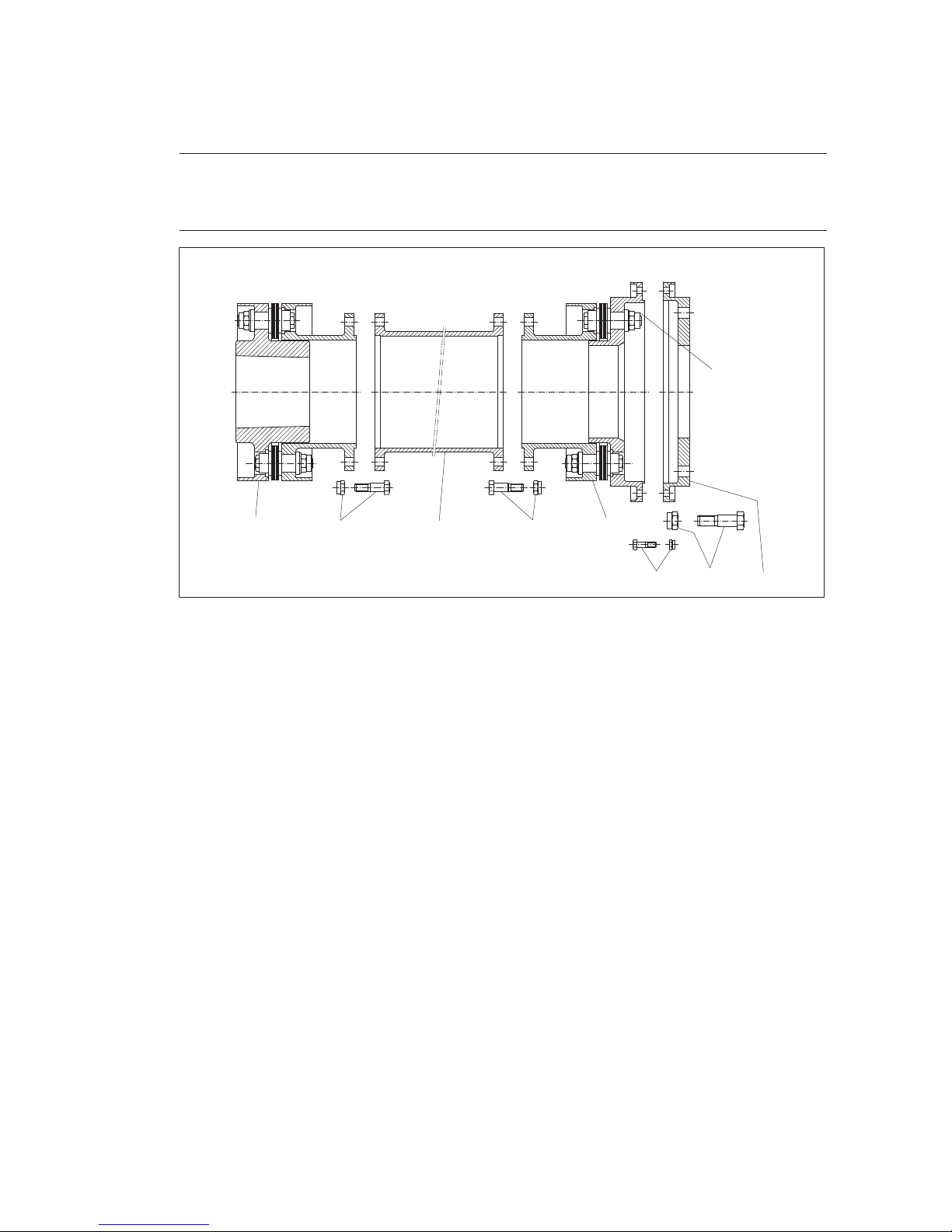
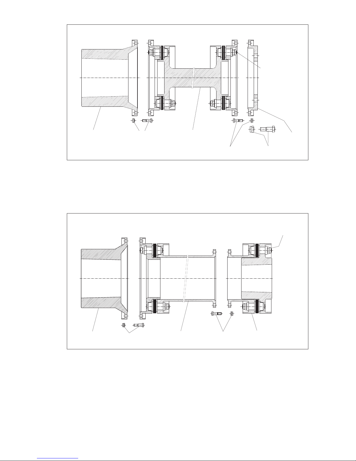
5.2.2 Special types
By exchanging individual coupling components and coupling modules, additional types can be generated
on the basis of the standard types (see item 5.2.1). As an example three special types, BVFF, MWF and
MFB, are shown in this section (see figs. 10 to 12).
Note
The exact arrangement of the coupling components, coupling modules, screw connections of the
flanges and further accessories such as shims can be found on the orderspecific drawing of the
coupling.
BVFF
12355
455
*)
Fig. 10: Special type BVFF
1"B" module 2 "V"-spacer (intermediate unit)
3"F" module 4 "F" flange
5 Screw connection of flange
*)The plate packs must not be demounted or retightened!
Page 20
20
ARPEX 8706 en
Operating instructions 10/2017
MWF
14 2 3
44
*)
Fig. 11: Special type MWF
1"M" hub 2 "W" module (intermediate unit)
3"F" flange 4 Screw connection of flange
*)The plate packs must not be demounted or retightened!
MFB
14 2 43
*)
Fig. 12: Special type MFB
1"M" hub 2 "F" module (intermediate unit)
3"B" module 4 Screw connection of flange
*)The plate packs must not be demounted or retightened!
Page 21
21
ARPEX 8706 en
Operating instructions 10/2017
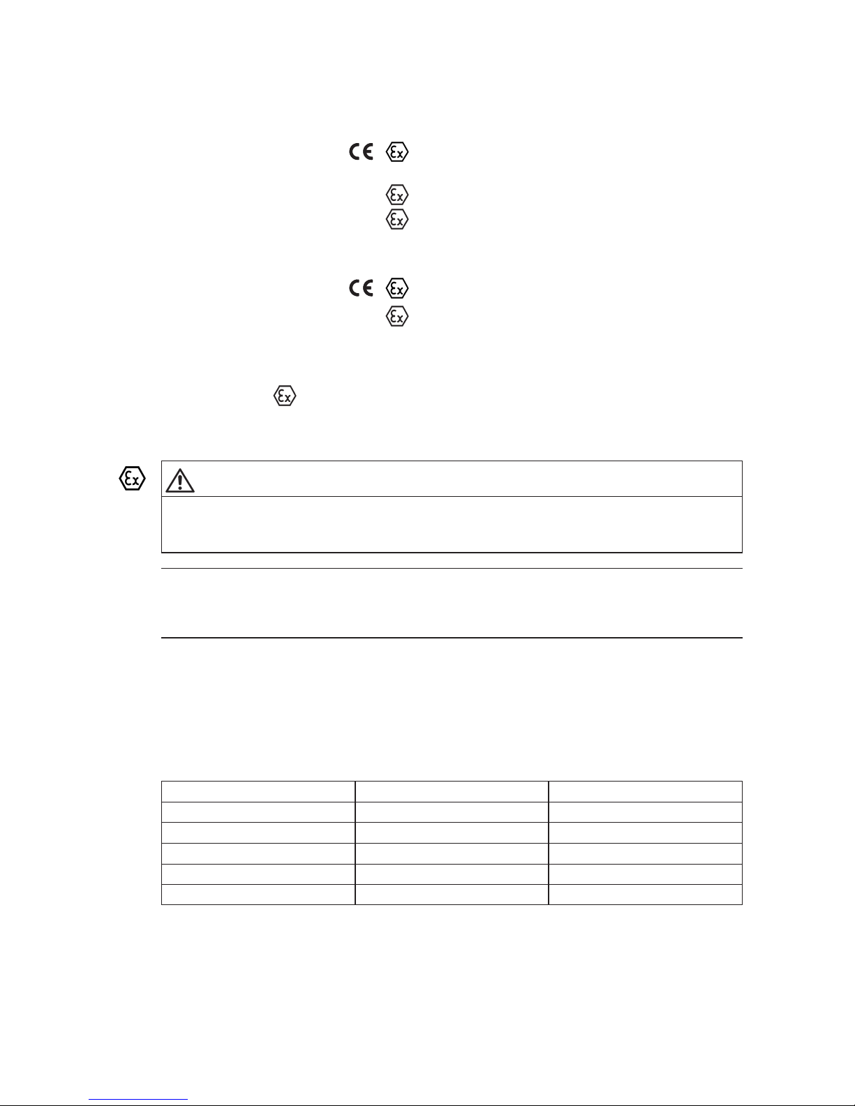
5.3 Marking of the coupling parts for use in potentially explosive areas
Couplings which are ordered in ATEX configuration, have the following marks on the outer circumference
of one of the coupling parts (e.g. on the hub):
Complete mark:
Flender GmbH
II 2G c IIC T2/T3/T4/T5/T6
46395 Bocholt - Germany -40 °C ≤ Ta ≤ +260 °C/+180 °C/+115 °C/+80 °C/+65 °C
FLENDER couplings ARPEX
II 2D c T 120 °C -40 °C ≤ Ta ≤ +100 °C
<year built>
I M2 c -40 °C ≤ Ta ≤ +130 °C
Abbreviated mark:
Flender GmbH
II 2GD c IIC TX
46395 Bocholt - Germany
I M2 c X
FLENDER couplings ARPEX <year built>
All other coupling components, with the exception of the screw connection of the flanges and the shims,
must be marked by
.
5.4 Operating conditions
DANGER
Danger of explosion
When using unsuitable components in potentially explosive areas there is a risk of explosion .
Use the coupling only for the approved zones and equipment groups. In case of doubt, contact Flender.
Note
Marked couplings and/or coupling parts as described in item 5.3 "Marking of the coupling parts
according to Directive 2014/34/EU" are suited for the operating conditions defined in Directive
2014/34/EU mentioned below.
• Equipment group II (use above ground) of categories 2 and 3 for areas where there are
explosible gas, vapour, mist, air mixtures as well as for areas where dust can form explosible
atmospheres.
Depending on the assigned temperature class, the following maximum ambient temperature
in the immediate vicinity of the coupling, or maximum surface temperature of the coupling are
permitted.
Table 1: Temperature classes
Ambient temperature Temperature class Max. surface temperature
- 40 °C up to max. + 230 °C T2 less than 280 °C
- 40 °C up to max. + 150 °C T3 less than 200 °C
- 40 °C up to max. + 85 °C T4 less than 135 °C
- 40 °C up to max. + 50 °C T5 less than 100 °C
- 40 °C up to max. + 35 °C T6 less than 85 °C
• Equipment group I (underground applications) of the category M2.
Page 22
22
ARPEX 8706 en
Operating instructions 10/2017
5.5 Condition on delivery
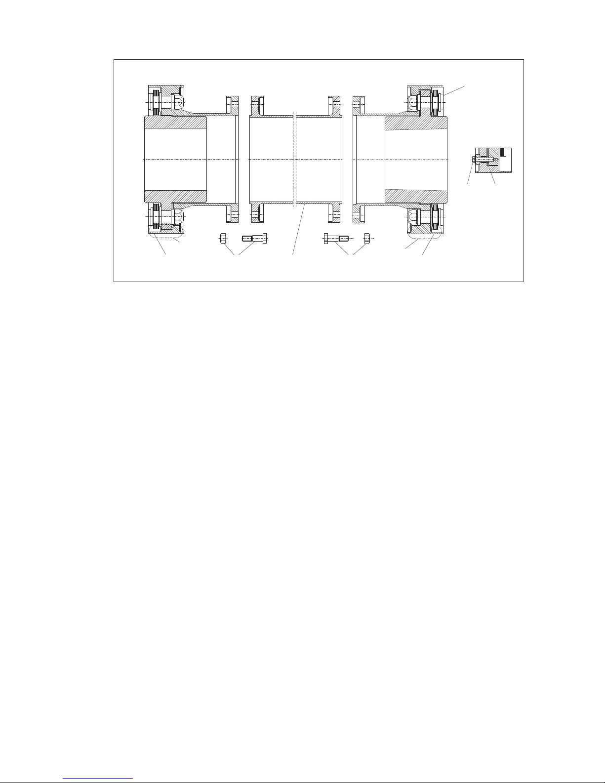
5.5.1 Type BVB
Y
Y
Detail "Y"
45
1
1
2
3
2
*)
B
V
B
Fig. 13: Type BVB
1 "B" module 2 Screw connection of flange
3 "V"-spacer (intermediate unit) 4 Cheese-head bolt
5 Distance bushes "Y" Fastening
*)The plate packs must not be demounted or retightened!
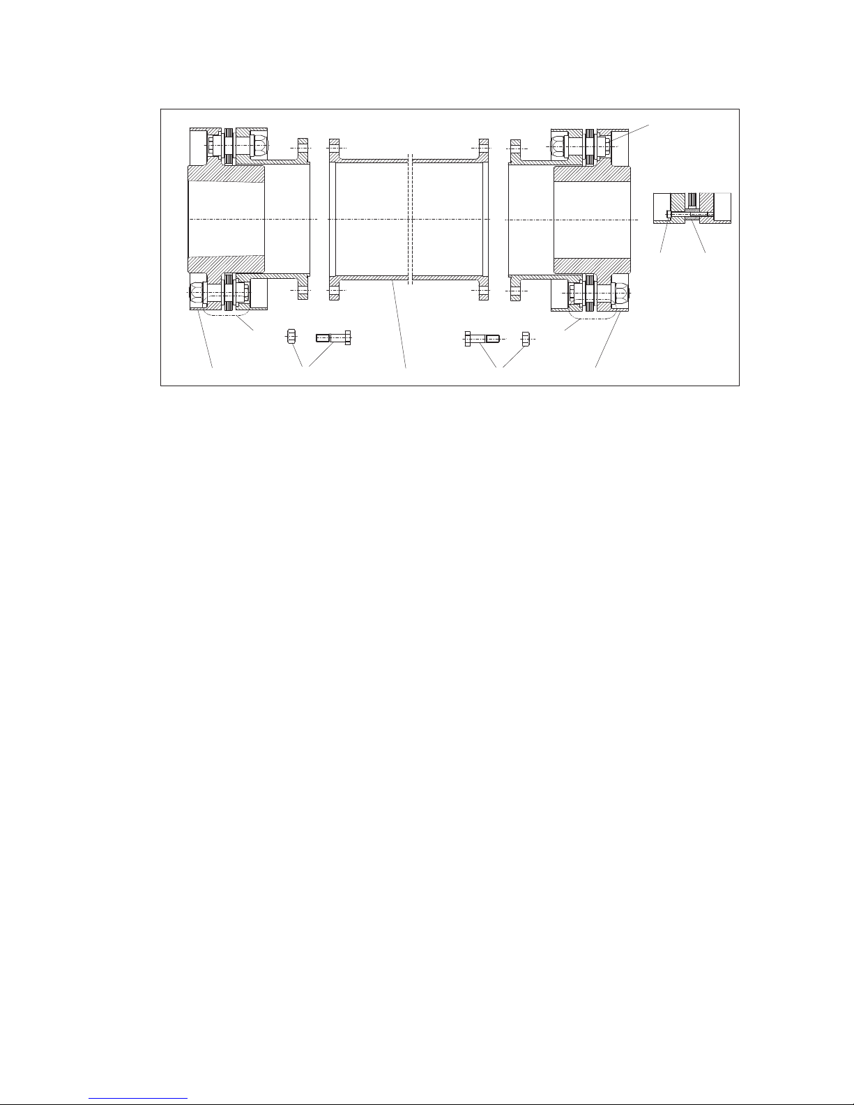
The plate packs have been secured for the transport with special fastenings (spacer bushes and
cheesehead screws; see detail "Y" in figure 13).
The screw connections of the flanges (see figure 13) are delivered in separate packing units for each
coupling. The packing unit may contain additional spare screw connections.
Depending on the coupling version, optionally shims may be delivered, which are used for compensating
the shaft distance "DBSE" (DBSE = distance between shaft ends). The procedure is described in item 6.6.
Page 23
23
ARPEX 8706 en
Operating instructions 10/2017
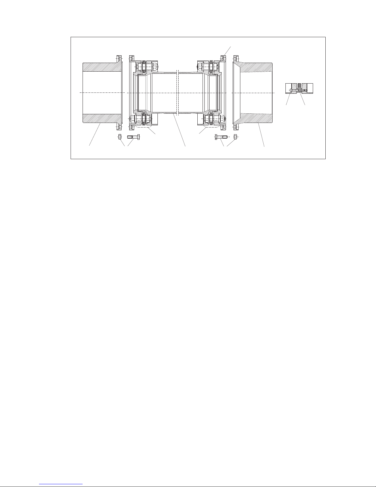
5.5.2 Type XVX
1
3
2
1
45
2
*)
"Y"
"Y"
Detail "Y"
X
VX
Fig. 14: Type XVX
1"X" module 2 Screw connection of flange
3"V"-spacer (intermediate unit) 4 Collar bolt
5 Threaded bush "Y" Fastening
*)The plate packs must not be demounted or retightened!
The plate packs have been secured for the transport with special fastenings (collar bolts and threaded
bushes; see detail "Y" in figure 14).
The screw connections of the flanges (see figure 14) are delivered in separate packing units for each
coupling. The packing unit may contain additional spare screw connections.
Depending on the coupling version, shims may be delivered, which are used for compensating the shaft
distance "DBSE". The procedure is described in item 6.6.
Page 24
24
ARPEX 8706 en
Operating instructions 10/2017
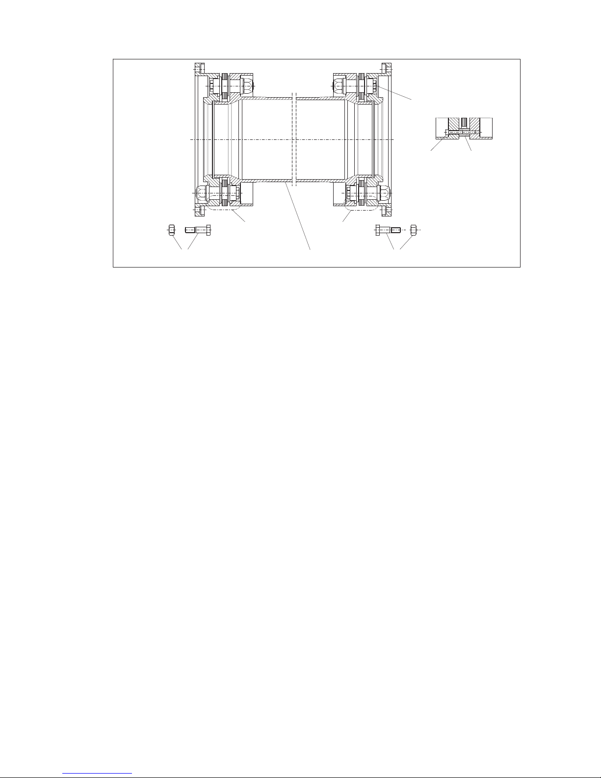
5.5.3 Type MHM
Detail "Y"
4
5
Y
Y
1
1
2
2
3
*)
M
M
H
Fig. 15: Type MHM
1 "M" hub 2 Screw connection of flange
3 "H" module (intermediate unit) 4 Cheese-head bolt
5 Distance bushes "Y" Fastening
*)The plate packs must not be demounted or retightened!
The plate packs have been secured for the transport with special fastenings (spacer bushes and
cheesehead screws; see detail "Y" in figure 15).
The screw connections of the flanges (see figure 15) are delivered in separate packing units for each
coupling. The packing unit may contain additional spare screw connections.
Depending on the coupling version, shims may be delivered, which are used for compensating the shaft
distance "DBSE". The procedure is described in item 6.6.
Page 25
25
ARPEX 8706 en
Operating instructions 10/2017
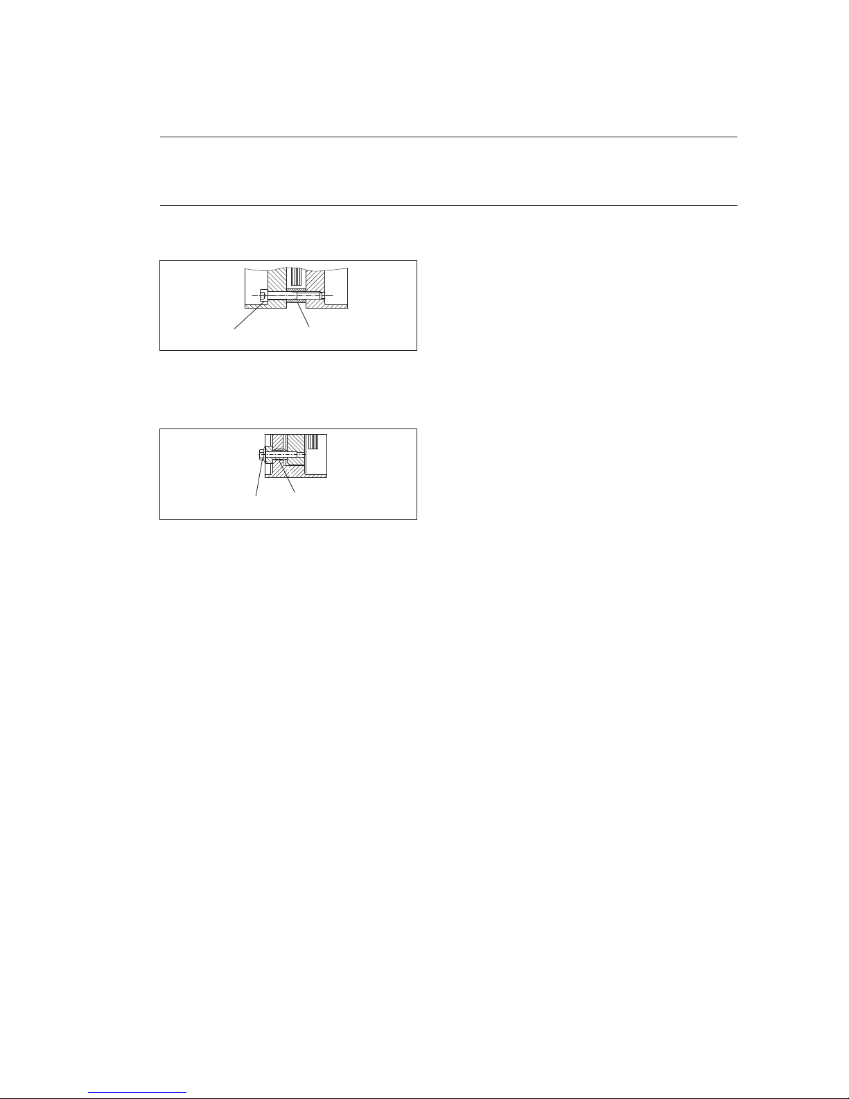
5.5.4 Type with "H" module
Detail "Y"
Y
1
Y
2
2
3
4
*)
H
Fig. 16: Type with "H" module
1 "H" module (intermediate unit) 2 Screw connection of flange
3 Cheese-head bolt 4 Distance bushes
"Y" Fastening
*)The plate packs must not be demounted or retightened!
This type with the "H" module consist as a rule of two flanges, which are bolted to the customer’s flanges,
of two plate packs and an intermediate spacer.
The plate packs have been secured for the transport with special fastenings (spacer bushes and
cheesehead screws; see detail "Y" in figure 16).
The screw connections of the flanges (see figure 16) are delivered in separate packing units for each
coupling. The packing unit may contain additional spare screw connections.
Depending on the coupling version, shims may be delivered, which are used for compensating the shaft
distance "DBSE". The procedure is described in item 6.6.
Page 26
26
ARPEX 8706 en
Operating instructions 10/2017
5.5.5 Special types
All types of the ART/ARE series are made up of individual coupling components (e.g. "M" hubs, "V"
spacers and/or "F" flanges) and coupling modules (e.g. "B" module and/or "H" module), which comprise
the plate packs.
Note
The exact arrangement of the coupling components, coupling modules, screw connections of the
flanges and further accessories such as shims can be found on the orderspecific drawing of the
coupling.
For the transport the plate packs of the coupling modules have been secured with fastenings. The design
of the fastenings depends on the type of coupling (see orderspecific drawing of the coupling).
1 2
Fig. 17: Fastening of the plate packs with distance bush
1 Cheese-head bolt
2 Distance bush
1
2
Fig. 18: Fastening of the plate packs with threaded bush
1 Collar bolt
2 Threaded bush
The screw connections of the flanges are delivered in separate packing units for each coupling. The
packing unit may contain additional spare screw connections.
Depending on the coupling version, shims may be delivered, which are used for compensating the shaft
distance "DBSE". The procedure is described in item 6.6.
Page 27
27
ARPEX 8706 en
Operating instructions 10/2017
6. Fitting
6.1 General information on fitting
Observe the instructions in section 3, "Safety instructions"!
Fitting work must be done with great care by trained and qualified personnel (see "Qualified personnel" on
page 3 of this manual).
As early as during the planning phase it must be ensured that sufficient space is available for installation
and subsequent care and maintenance work.
Adequate lifting equipment must be available before beginning the fitting work.
DANGER
Danger of explosion
Risk of explosion when operating in potentially explosive areas.
The conductivity and coating thickness of the paint applied may give rise to electrostatic charges and
are potential ignition sources.
If coated couplings are used in potentially explosive areas, the requirements made of the conductivity
of the coating and the limitation on the thickness of the coat applied must be observed in accordance with
standard "DIN EN 134631". Where coatings have a thickness < 200 μm, no electrostatic charge is to
be expected. Where coatings are thicker than 200 μm, an electrostatic charge, e.g. by cleaning the
coupling, must be avoided.
DANGER
Danger of explosion
Risk of explosion when operating in potentially explosive areas through damage.
Damaged coupling modules and coupling parts are potential explosion hazards.
Use only undamaged coupling components. Operating the coupling with damaged coupling parts is not
permitted in potentially explosive environments in accordance with Directive 2014/34/EU.
DANGER
Danger of explosion
Risk of explosion when operating in potentially explosive areas.
Incorrect changes made to the coupling will create ignition sources.
Any changes on the part of the user are not permitted. This applies equally to safety features designed
to prevent accidental contact. For the use in potentially explosive environments the protective
equipment must comply at least with type of protection IP2X.
WARNING
Risk of serious injury through flying fragments
Risk of serious injury through flying fragments and/or risk of damage to the coupling.
– The order of the described fitting steps must be adhered to.
– Adhere to specified tightening torques. Observe the instructions relating to cleaning and/or treatment
of the bolts with auxiliary materials.
– No welding work must be done at all on the coupling.
– Only undamaged coupling parts must be used. In particular the teeth, holes, screw threads and joining
and sealing surfaces must not be damaged.
Page 28
28
ARPEX 8706 en
Operating instructions 10/2017
WARNING
Serious injury
Rotating components may cause injury during work on the still rotating coupling.
All work on the coupling must be carried out only when it is at a standstill.
The drive unit must be secured against being switched on accidentally (e.g. by locking the key switch
or removing the fuses from the power supply). A notice should be attached to the ON switch stating
clearly that work on the coupling is in progress. The relevant accident prevention regulations at the place
of installation apply as well.
CAUTION
Risk of corrosion burns through chemical substances
Avoid burns when working with corrosive cleaning agents.
Observe manufacturer’s instructions for handling cleaning agents and solvents.
Wear suitable personal protective equipment (gloves, safety glasses).
6.2 Preparation for fitting
Observe the safety instructions in section 6.1, "General information on fitting"!
Set the flange or shaft distance of the machines to be coupled exactly to the fitting length "DBSE", as
shown on the orderspecific drawing of the coupling. On axially pretensioned couplings adjust the
flange or shaft distance exactly to the fitting length "DBSE fitting". Exactly align the machines to be
coupled. The shaft distance "DBSE" can be adjusted with shims (see item 6.6). Shims form only an
optional part of the scope of delivery.
6.3 Screw connection of flange
Observe the safety instructions in section 6.1, "General information on fitting"!
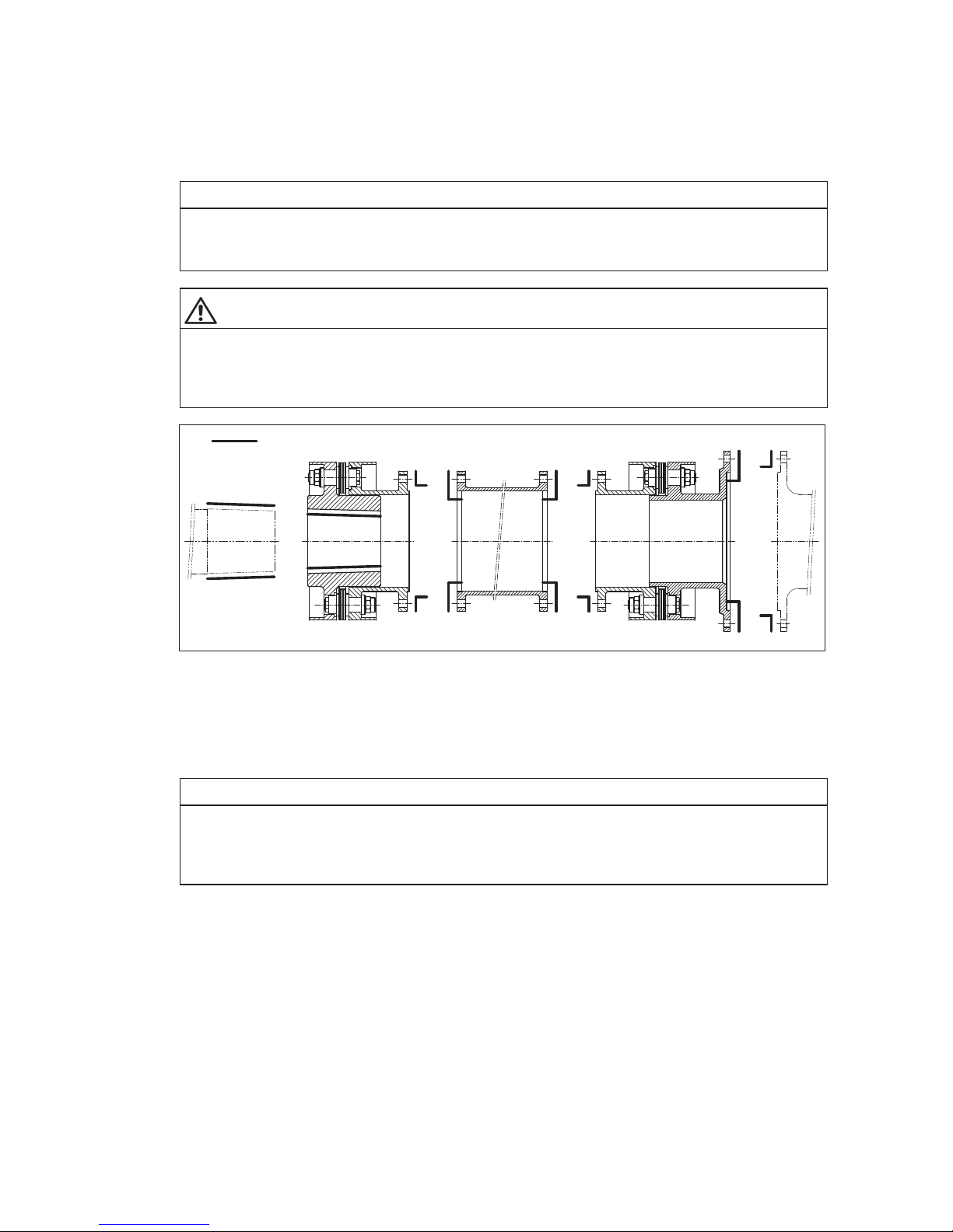
The screw connections of the flanges (see figures 6 to 16) are delivered in separate packing units for each
coupling. The packing unit may contain additional spare screw connections.
NOTICE
Damage to the coupling
Damage to the coupling and/or disruptions through the incorrect use of screw connections of the flanges.
The screw connections of the flanges have been checked by weight and must always be used or
replaced in sets.
Page 29
29
ARPEX 8706 en
Operating instructions 10/2017
6.4 Fitting the coupling parts
Observe the safety instructions in section 6.1, "General information on fitting"!
• Before starting the fitting the contact surfaces of all the coupling parts and the customer’s
connecting flanges and the shaft ends and hub bores must be freed of any rustpreventive medium
and carefully cleaned (see figure 19).
NOTICE
Damage to the coupling
Damage to the coupling and/or disruptions through insufficient cleaning.
The surfaces to be joined must be absolutely clean and greasefree.
CAUTION
Risk of corrosion burns through chemical substances
Avoid burns when working with corrosive cleaning agents.
Observe manufacturer’s instructions for handling cleaning agents and solvents.
Wear suitable personal protective equipment (gloves, safety glasses).
xx
Fig. 19: Preparing the surfaces
xx Surfaces cleaned and free from grease
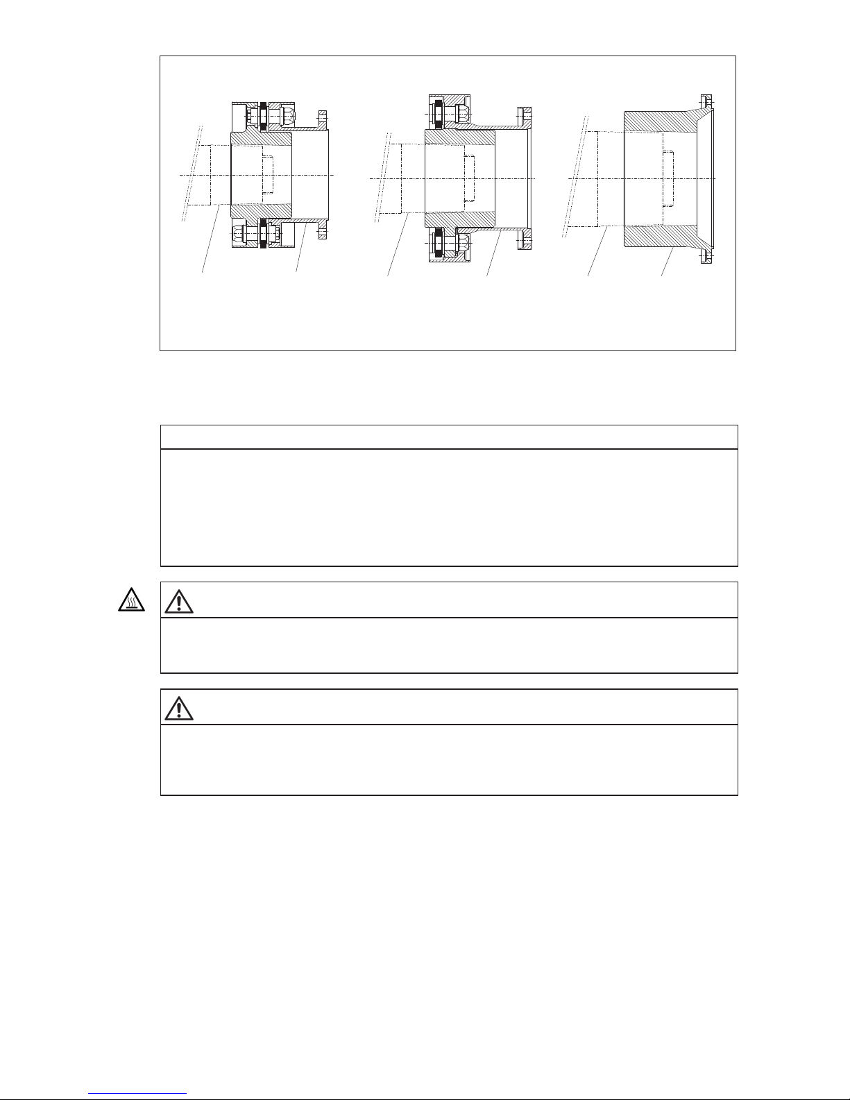
6.4.1 Fitting "B", "X" modules and "M"hubs
Observe the safety instructions in section 6.1, "General information on fitting"!
NOTICE
Damage to the coupling, damage to other components
Damage to the coupling, the bearings and the shaft through incorrect pulling on.
The coupling parts must be fitted with the aid of suitable equipment to avoid damaging the shaft bearings
through axial joining forces. Use suitable lifting gear.
Page 30
30
ARPEX 8706 en
Operating instructions 10/2017
3
4
3
1
3
2
B
X
M
Fig. 20: Fitting "B", "X" modules and "M"hubs
1"B" module
3 Shaft end
2"M" hub
4"X" module
NOTICE
Material damage
Damage to the coupling and the shaft.
– The information specified on the dimensioned drawing relating to the pullingon path must be
observed.
– Observe the orderrelated entries on the drawing of the coupling relating to the joining temperature.
WARNING
Danger of burns
Serious injury through burns on hot surfaces (> 55 °C) possible.
Wear suitable protective gloves and protective clothing.
WARNING
Risk of serious injury through flying fragments
Risk of serious injury through flying fragments and/or risk of damage to the coupling.
The coupling parts must be held in position on the shaft with the aid of a suitable retaining device, until
they cool down and seat firmly.
Page 31
31
ARPEX 8706 en
Operating instructions 10/2017
6.4.2 Fitting "F" flanges
Observe the safety instructions in section 6.1, "General information on fitting"!
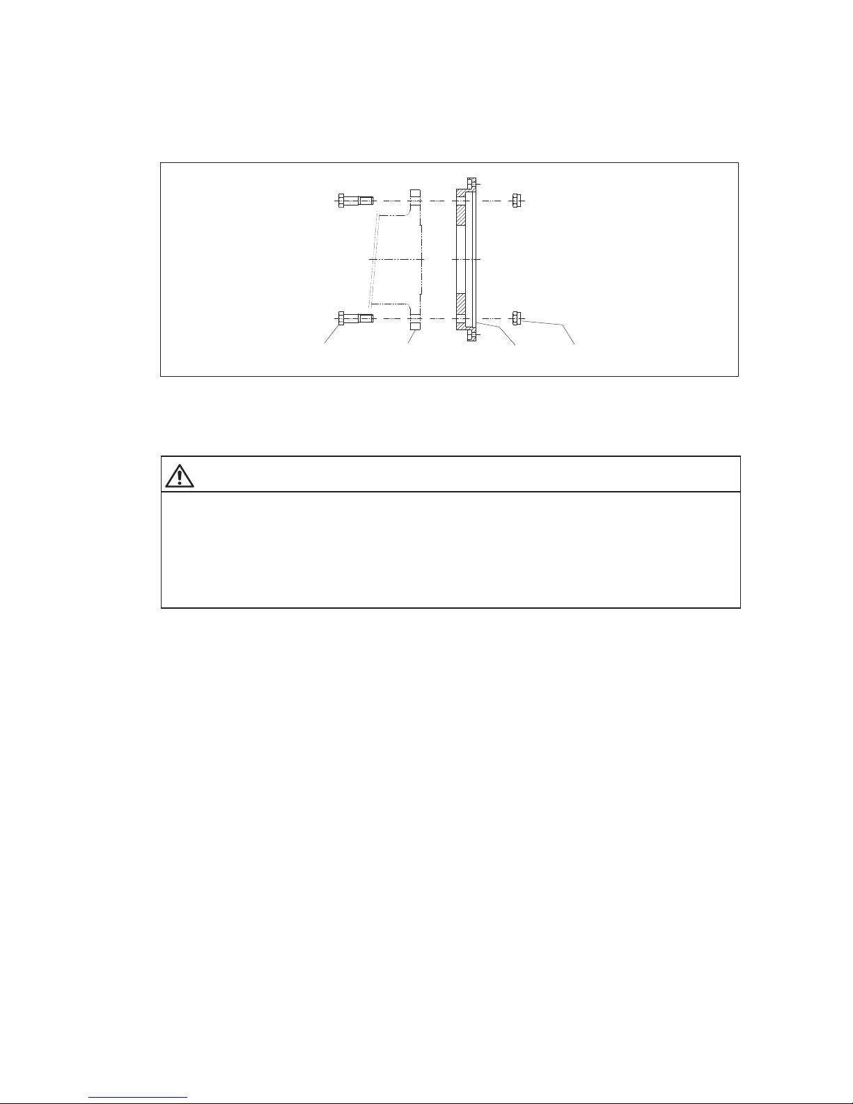
Screw the "F" flange with the screw connection of the flange on the connecting flange of the machine to
be coupled (see figure 21). Tighten the screw connection of the flange gradually one after the other to the
prescribed tightening torque (for tightening torque, see orderspecific drawing of the coupling).
1323
Fig. 21: Fitting "F" flanges
1"F" flange 2 Connecting flange
3 Screw connection of flange
WARNING
Risk of serious injury through flying fragments
Risk of serious injury through flying fragments and/or risk of damage to the coupling.
– Locking nuts must only be used three times, to guarantee the locking properties.
– Adhere to specified tightening torques. Observe the instructions relating to cleaning and/or treatment
of the bolts with auxiliary materials.
6.4.3 Fitting "F" and "D" modules
Observe the safety instructions in section 6.1, "General information on fitting"!
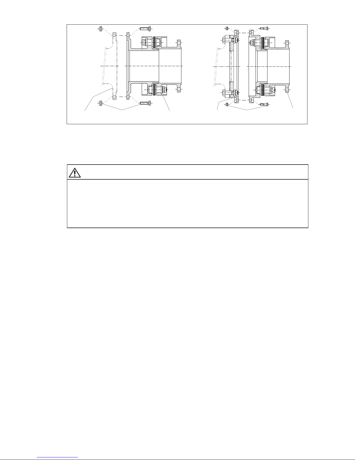
Screw the "F" or "D" module with the screw connection of the flange to the already fitted "F" flange or with
the screw connection of the flange to the connecting flange of the machines to be coupled (see figure 22).
Tighten the screw connection of the flange gradually one after the other to the prescribed tightening torque
(for tightening torque, see orderspecific drawing of the coupling).
Page 32
32
ARPEX 8706 en
Operating instructions 10/2017
4 35512
Fig. 22: Fitting "F" and "D" modules
1"D" module 2 "F" flange (fitted)
3"F" module 4 Connecting flange
5 Screw connection of flange
WARNING
Risk of serious injury through flying fragments
Risk of serious injury through flying fragments and/or risk of damage to the coupling.
– Locking nuts must only be used three times, to guarantee the locking properties.
– Adhere to specified tightening torques. Observe the instructions relating to cleaning and/or treatment
of the bolts with auxiliary materials.
6.5 Test run of the customer’s shaft with fitted coupling parts
Observe the safety instructions in section 6.1, "General information on fitting"!
If a test run of the customer’s shaft with fitted coupling parts and any weight simulators must be performed,
if necessary, this should be done in accordance with the configuration described in item 6.10.
6.6 Compensation of the flange or shaft distance "DBSE"
Observe the safety instructions in section 6.1, "General information on fitting"!
"DBSE" = distance between shaft ends
Set the flange or shaft distance between the machines to be coupled exactly to the fitting
dimension "DBSE" (on axially pretensioned couplings "DBSE fitting"), as shown on the orderspecific
drawing of the coupling.
Lengths can be adjusted with shims. These are mainly used with tapering shaft ends and customer’s
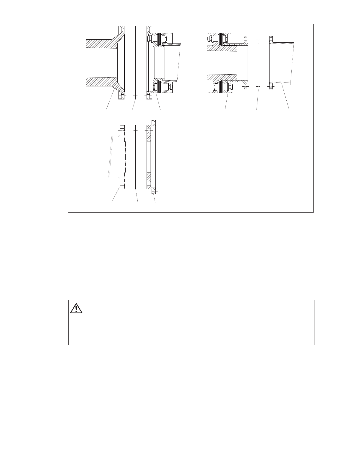
connecting flanges. Shims form only an optional part of the scope of delivery. The position of the shims can
be seen on the orderspecific drawing of the coupling. As a rule, they are fitted between the fitted
coupling part (e.g. "M"hub or "B" module, see figure 23) and the intermediate unit (e.g. "H" module or
"V" spacer, see figure 23). With customer’s connecting flanges they can also be fitted between the fitted
coupling part (e.g. "F" flange, see figure 23) and the customer’s flange.
Page 33
33
ARPEX 8706 en
Operating instructions 10/2017
123 514
176
Fig. 23: Fitting shims
(Shims, basic illustration: "X" module identical with "B" module)
1 Shims 2 "M" hub
3"H" module 4 "B" module
5"V"-spacer 6 Connecting flange
7"F" flange
The number of shims to be used can be found on the orderspecific drawing of the coupling (see table
"Fitting data"). The normal dimension is reached with half the delivered shims. The shims are pushed onto
the "recesses" (centering pin) of the connecting flanges before fitting the screw connections of the flanges.
WARNING
WARNING
Risk of serious injury through flying fragments
Risk of serious injury through flying fragments and/or risk of damage to the coupling.
The maximum number of shims to be used per "recess" (centering pin) must not be exceeded (see table
"Fitting data" on the orderspecific drawing of the coupling).
Page 34
34
ARPEX 8706 en
Operating instructions 10/2017
6.7 Fitting of assemblybalanced couplings
Observe the safety instructions in section 6.1, "General information on fitting"!
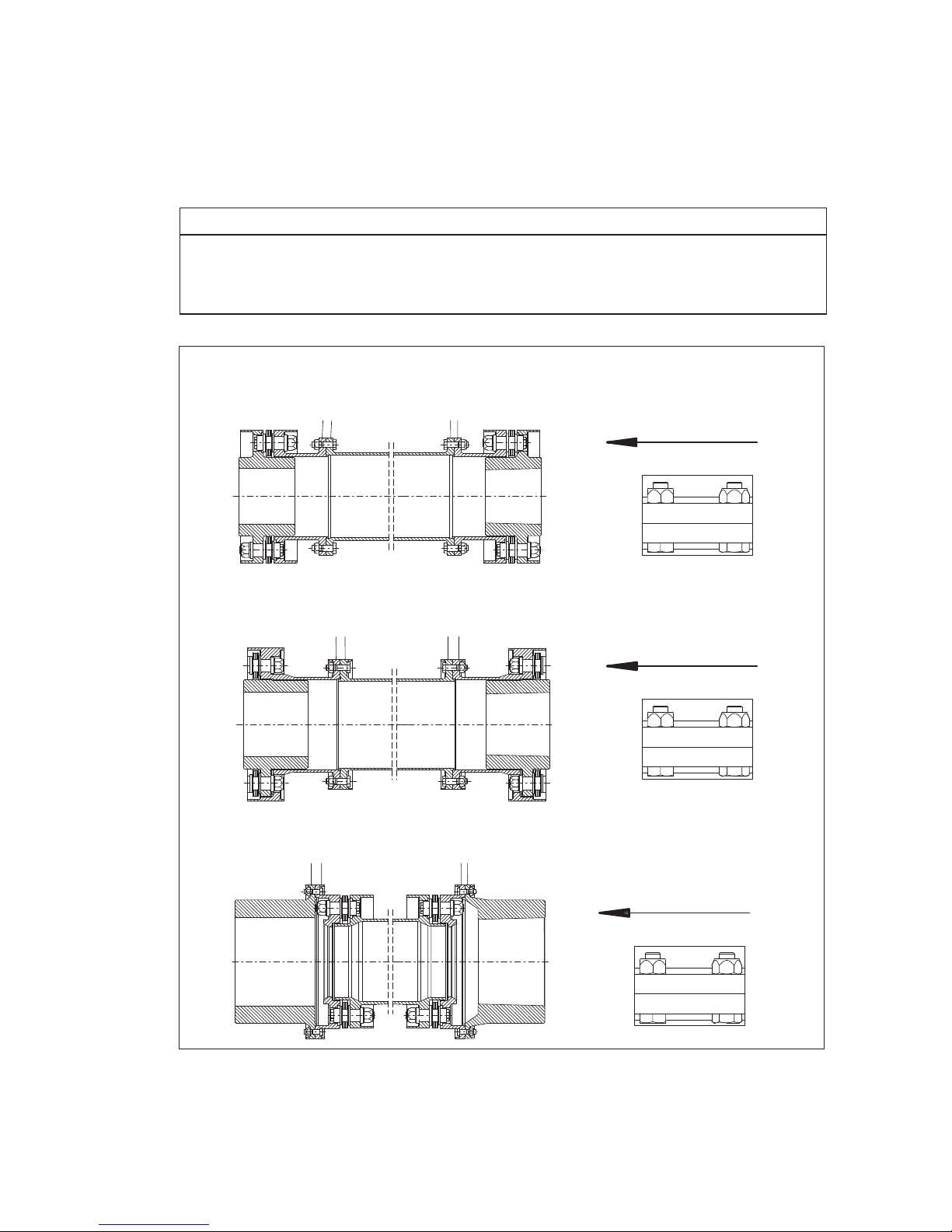
On couplings which have been assemblybalanced each individual coupling component must be marked
on the outside circumference of the screwon flanges with a multidigit number (see marking "XXXXX"
in figure 24). When assembling, care must be taken that only coupling parts having the same numbers on
the outside circumference of the flange are bolted together.
NOTICE
Damage to the coupling
Risk of damage to the coupling through incorrect assembly.
After correct fitting the identical numbers of the parts must be arranged in line and be legible from one
direction (see marking "XXXXX" in figure 24).
1
12345
12345
BVB
X
X
X
X
X
XVX
1
12345
12345
MHM
1
12345
12345
X
X
X
X
X
X
X
X
X
X
X
X
X
X
X
X
X
X
X
X
X
X
X
X
X
X
X
X
X
X
X
X
X
X
X
X
X
X
X
X
X
X
X
X
X
X
X
X
X
X
X
X
X
X
X
Fig. 24: Marking in case of assembly balancing
1 legible from one direction
Page 35
35
ARPEX 8706 en
Operating instructions 10/2017
6.8 Fitting the intermediate unit
Observe the safety instructions in section 6.1, "General information on fitting"!
• Clean the surfaces to be joined; they must be absolutely clean and greasefree.
CAUTION
Risk of corrosion burns through chemical substances
Avoid burns when working with corrosive cleaning agents.
Observe manufacturer’s instructions for handling cleaning agents and solvents.
Wear suitable personal protective equipment (gloves, safety glasses).
6.8.1 Procedure applying to modules with distance bush
Observe the safety instructions in section 6.1, "General information on fitting"!
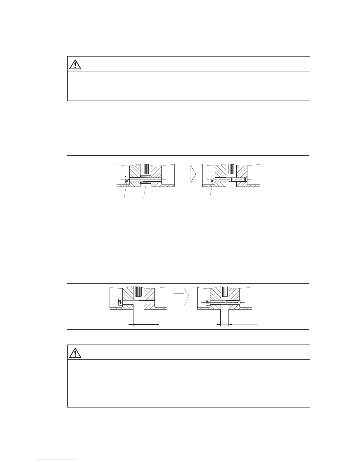
The design of the fastening is shown on the orderspecific drawing of the coupling.
Unscrew the cheesehead bolts (pos. 1, figure 25) of the fastening and remove the distance bushes
(pos. 2, figure 25).
1
2
1
Fig. 25: Removing the distance bush from the fastening
1 Cheese-head bolt 2 Distance bush
Screw in the cheesehead bolts of the fastening again. The plate packs of the fitted modules (e.g. "B"
module, "D" module or "F" module, see figs. 6 to 16) or the intermediate unit ("H"
module, "W" module
or "F" module (see figures 6 to 16) must be axially clinched to a dimension of S1
fitting
(see table "Fitting
data" on the orderspecific drawing of the coupling). The intermediate unit ("H" module, "W" module,
"F" module or "V" spacer (see figures 6 to 16)) must fit between the fitted coupling parts or the customer’s
connecting flanges (see figure 28, figure 29 and figure 30).
S1
fitting
S1
Fig. 26: Illustration S1
fitting
WARNING
Risk of serious injury through flying fragments
Risk of serious injury through flying fragments and/or risk of damage to the coupling through the plate
packs being too tightly clinched during the fitting procedure
The plate packs may be clinched to a maximum dimension of S1
fitting
(see figure 26) for fitting and
disassembly. The value in the table "Fitting data" on the orderspecific drawing of the coupling must be
adhered to.
The instructions relating to the assemblybalanced couplings in item 6.7 must be observed.
Page 36
36
ARPEX 8706 en
Operating instructions 10/2017
If necessary, move axially the shaft ends of the machines to be joined together and after fitting the
intermediate unit set exactly to the dimension "DBSE" (see orderspecific drawing of the coupling).
6.8.2 Procedure applying to modules with threaded bush
Observe the safety instructions in section 6.1, "General information on fitting"!
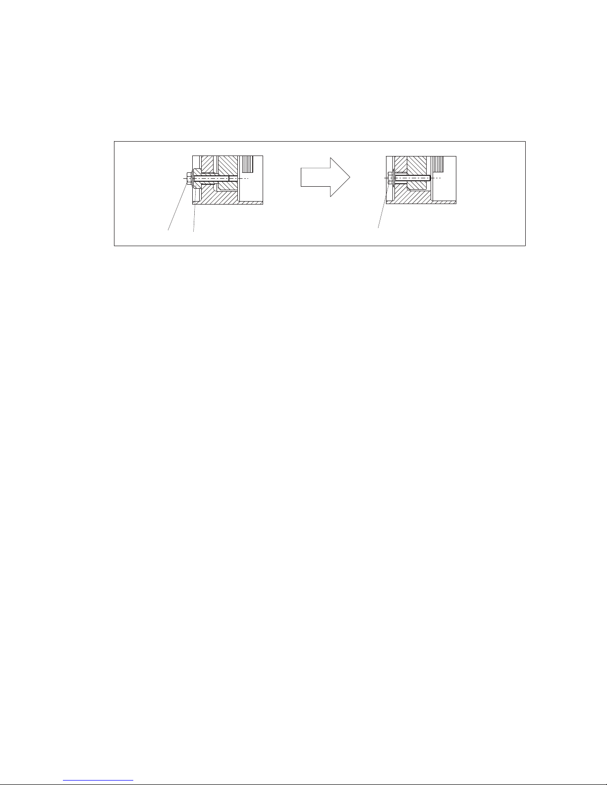
The design of the fastening is shown on the orderspecific drawing of the coupling.
Unscrew the collar bolt from the fastening and remove the threaded bushes (see figure 27).
1
2
1
Fig. 27: Unscrewed threaded bush of the fastening
1 Collar bolt 2 Threaded bush
Screw in the collar bolts of the fastening again. The plate packs of the fitted "X" modules are clinched
axially by tightening the bolts. Tighten the bolts of the coupling flanges as fas as they will go (figure 27).
The intermediate unit "V" spacer (see figures 7 and 14) must fit between the fitted coupling parts.
If necessary, additionally move axially the shaft ends of the machines to be joined together and after fitting
the intermediate unit set exactly to the dimension "DBSE" (see orderspecific drawing of the coupling)
again.
Page 37
37
ARPEX 8706 en
Operating instructions 10/2017
6.8.3 Fitting the intermediate unit
Observe the safety instructions in section 6.1, "General information on fitting"!
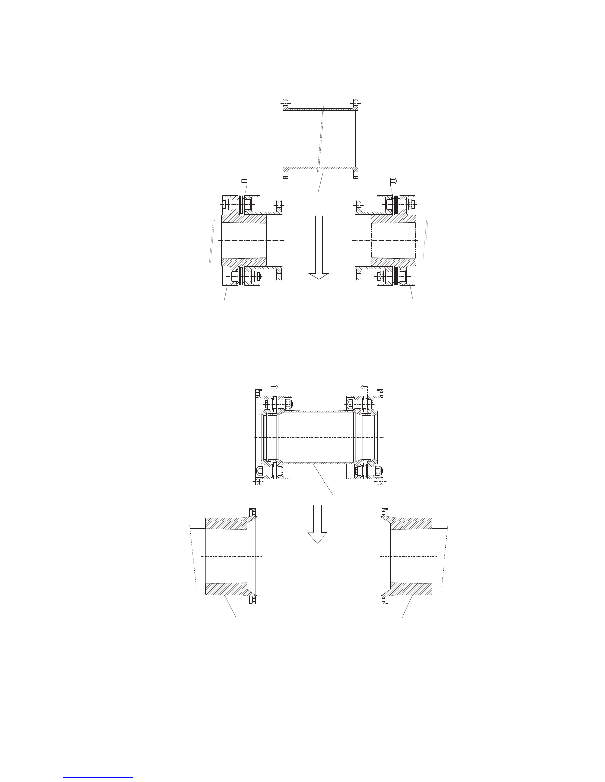
Insert intermediate unit between the fitted coupling parts (see figs. 28 and 29).
2
11
Fig. 28: Fitting intermediate unit type BVB and XVX (basic drawing BVB, XVX identical)
1 Fitted coupling part
(e.g. "B" module)
2 intermediate unit (e.g. "V"-spacer)
1
1
2
Fig. 29: Fitting intermediate unit type MHM (basic drawing)
1 fitted coupling part (e.g. "M" module) 2 intermediate unit (e.g. "H" module)
Page 38
38
ARPEX 8706 en
Operating instructions 10/2017
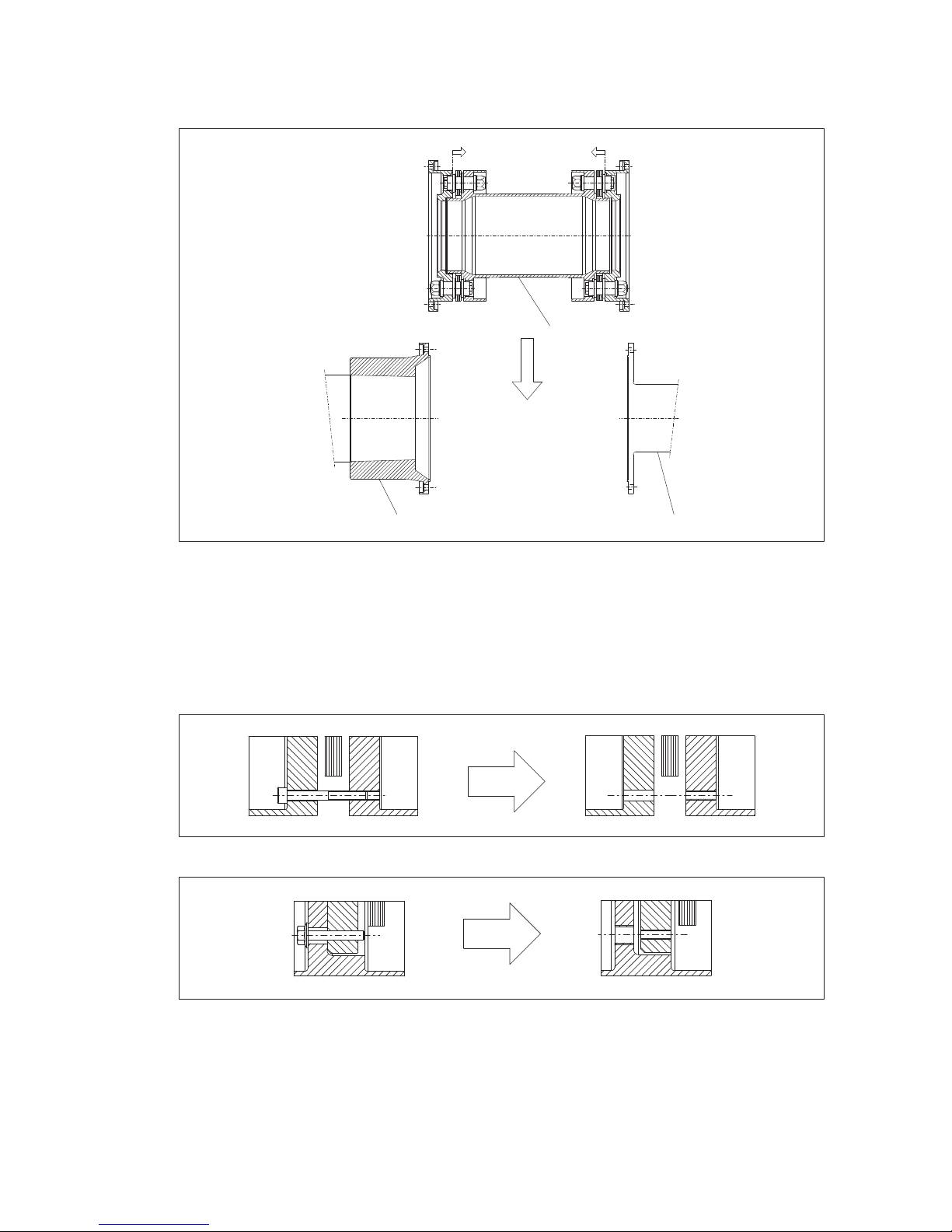
With single and twopart coupling versions with single or twoside customer’s coupling flange
(see e.g. type MH in figure 30) the intermediate unit is fitted between a fitted coupling part and a customer’s
connecting flange or between two connecting flanges of the customer.
1
3
2
Fig. 30: Twopiece coupling version MH with customer’s connecting flange on one side
1"M" hub (fitted coupling part) 2 "H" module (intermediate unit)
3 Customer’s flange
Insert the screw connection of the flange (see figs. 6 to 16) and tighten only handtight.
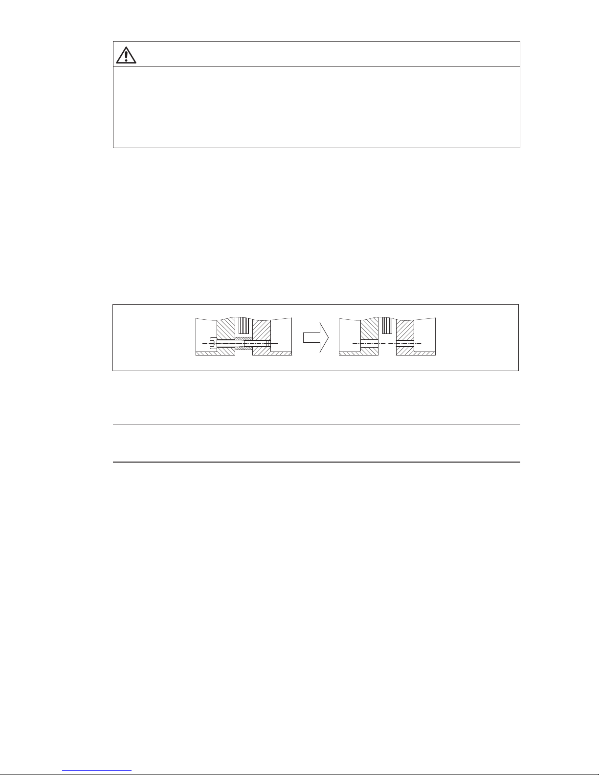
The design of the fastening is shown on the orderspecific drawing of the coupling.
Remove the bolts from the fastening (see figure 31 or figure 32).
Fig. 31: Removing the fastening in case of distance bush
Fig. 32: Removing the fastening in case of threaded bush
Tighten the screw connection of the flange gradually one after the other to the prescribed tightening torque
(for tightening torque, see orderspecific drawing of the coupling).
Page 39
39
ARPEX 8706 en
Operating instructions 10/2017
WARNING
Risk of serious injury through flying fragments
Risk of serious injury through flying fragments and/or risk of damage to the coupling.
– Locking nuts must only be used three times, to guarantee the locking properties.
– Adhere to specified tightening torques. Observe the instructions relating to cleaning and/or treatment
of the bolts with auxiliary materials.
6.9 Alignment
Observe the safety instructions in section 6.1, "General information on fitting"!
In general the machine parts to be joined together should always be optimally aligned. Since this is often
done with highprecision, optical equipment before the coupling components are assembled, in such
cases the alignment should be checked during or after assembly of the coupling only as an additional
safeguard. The fastening must be removed before aligning. The design of the fastening is shown on the
orderspecific drawing of the coupling.
6.9.1 Aligning with distance bush
Observe the safety instructions in section 6.1, "General information on fitting"!
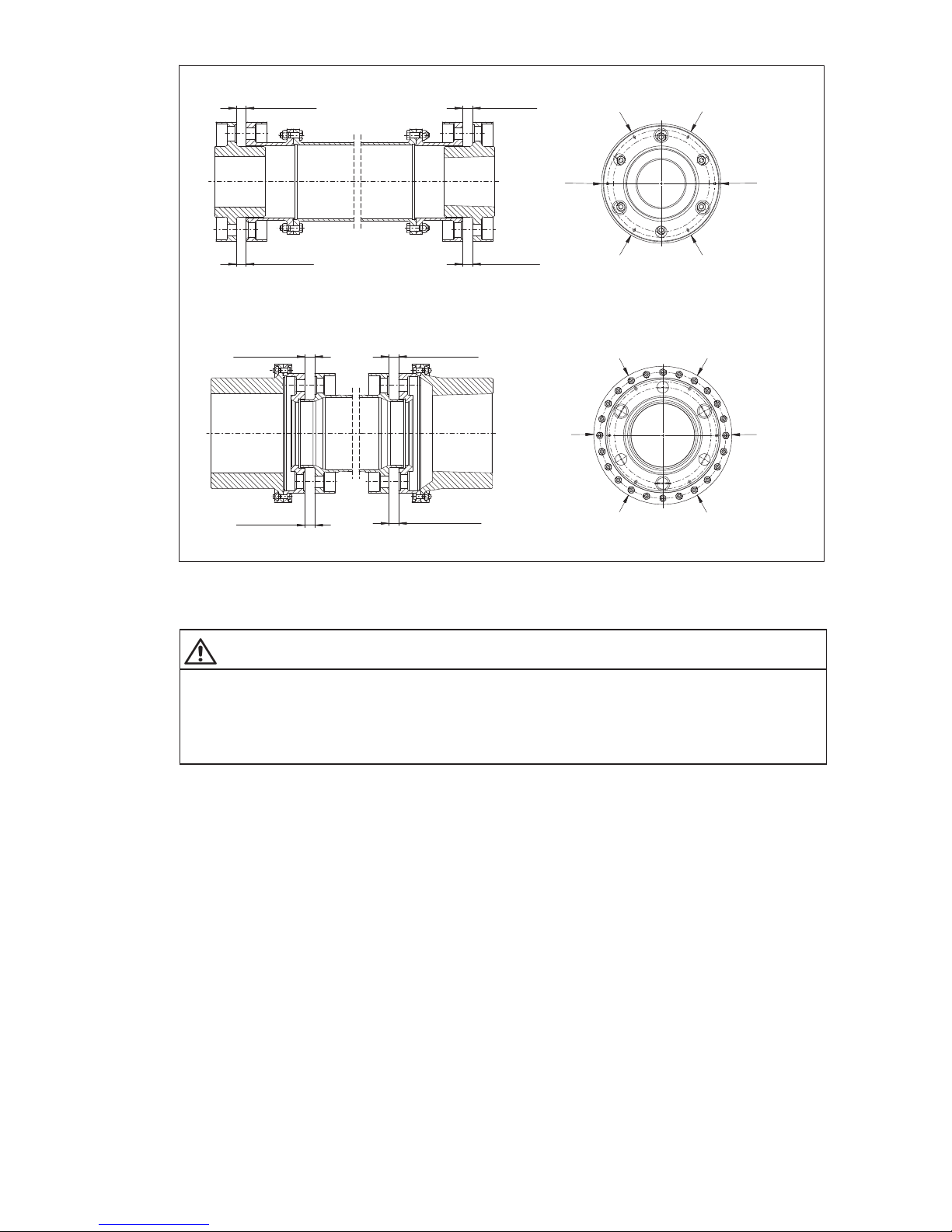
Unscrew the cheesehead bolts from the fastening and remove the distance bushes (see figure 33).
Fig. 33: Removing the fastening in case of distance bush
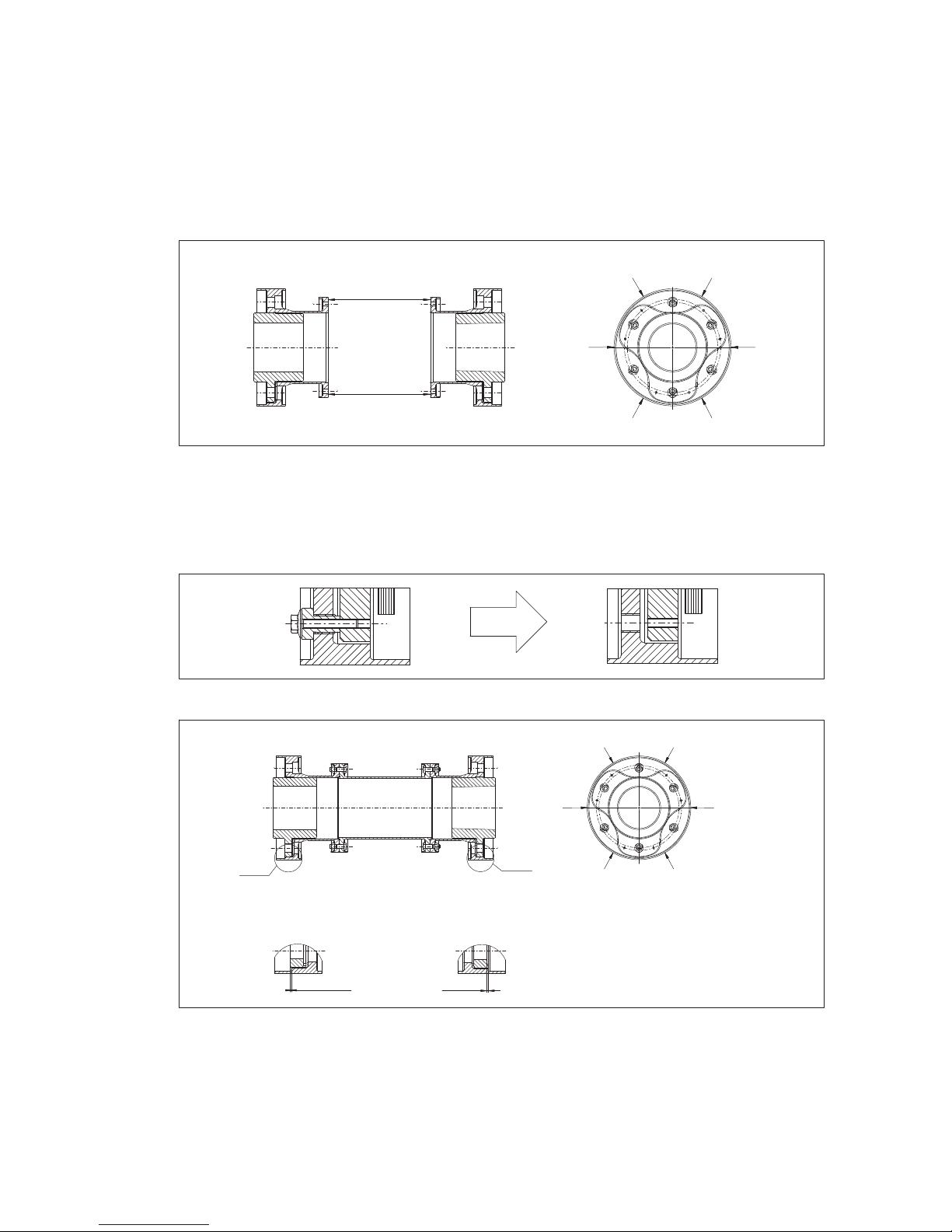
When aligning the machine parts, in case of modules with distance bush measure with a sliding caliper
gauge the distance "S1" (see figure 34) between the coupling flanges.
Note
The permissible values of "S1" are given in the table "Fitting data" on the orderspecific drawing of the
coupling.
Page 40
40
ARPEX 8706 en
Operating instructions 10/2017
S1
max
.
S1
min.
S1
min.
S1
max.
M
M
M
M
M
M
S1
max
.
S1
min.
S1
min.
S1
max.
M
M
M
M
M
M
BVB
MHM
Fig. 34: Flange distance "S1" and measuring points
M Measuring point
WARNING
Risk of serious injury through flying fragments
Risk of serious injury through flying fragments and/or risk of damage to the coupling.
The fitting misalignment must not exceed the values for S1
min.
and S1
max.
specified (figure 34). The
permissible values of "S1" are given in the table "Fitting data" on the orderspecific drawing of the
coupling.
Page 41
41
ARPEX 8706 en
Operating instructions 10/2017
6.9.2 Aligning with threaded bush
Observe the safety instructions in section 6.1, "General information on fitting"!
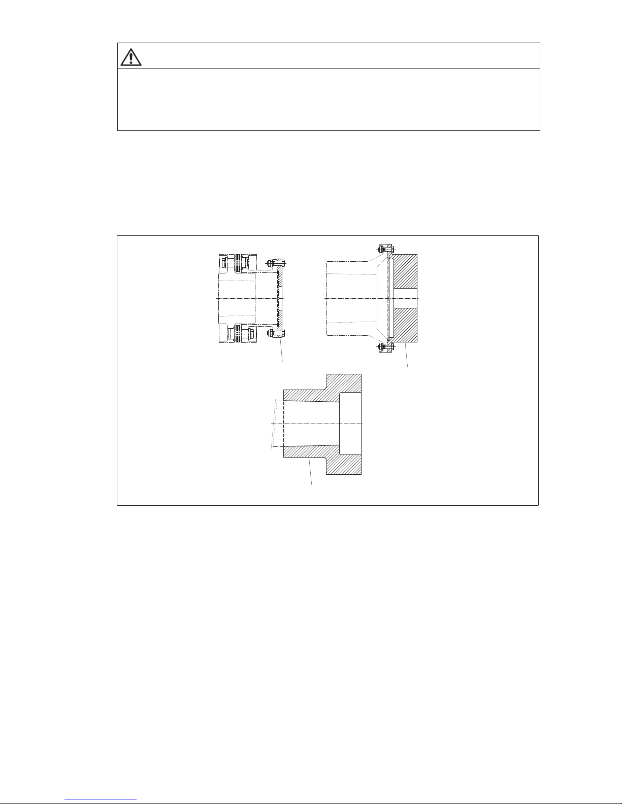
In the case of subassembly “X” with threaded bush either distance "S2" between the opposed
subassemblies or dimension "S3" inside subassembly "X" can be measured. The dimensions are taken
at several measuring points "M". The permissible values of "S2" and "S3" are given in the table "Fitting
data" on the orderspecific drawing of the coupling.
For measuring dimension "S2" the fastening must have been fitted. The design of the fastening is shown
on the orderspecific drawing of the coupling.
S2
max
.
S2
min.
M
XVX
M
M
M
M
M
Fig. 35: Measuring point "S2" with the XVX module
M Measuring point
Dimension "S3" is measured with the intermediate unit fitted. For measuring dimension "S3" the fastening
must be removed. The design of the fastening is shown on the orderspecific drawing of the coupling.
Unscrew and remove collar bolt and threaded bush (see figure 36).
Fig. 36: Removing the fastening in case of threaded bush
S3
max
.
S3
min.
M
M
M
M
M
M
Detail "Y"
Detail "Z"
"Z"
"Y"
XVX
Fig. 37: Measuring point "S3" with the XVX module
M Measuring point
Page 42
42
ARPEX 8706 en
Operating instructions 10/2017
WARNING
Risk of serious injury through flying fragments
Risk of serious injury through flying fragments and/or risk of damage to the coupling.
The fitting misalignment must not exceed the values specified for S2
min.
/ S3
min.
and S2
max.
and S3
max.
.
The permissible values of "S2" and "S3" are given in the table "Fitting data" on the orderspecific drawing
of the coupling.
6.10 Test run of the customer’s shaft with weight simulators
6.10.1 Definition of weight simulators for the test run
Observe the safety instructions in section 6.1, "General information on fitting"!
Depending on the customer’s specification, various aids that simulate the weight of the half couplings are
used for test runs. These aids (dummy flanges and dummies (see figure 38) are available from Flender on
request. They form only an optional part of the scope of delivery.
1
1
2
Fig. 38: Testrun aids
1 Dummy flange 2 Dummy
Dummy flange: A dummy flange is an element that is bolted onto a fitted coupling part. It simulates,
together with the coupling part, the centre of gravity and the weight of the half coupling.
Dummy: A dummy is an independent element that is mounted like a coupling hub on a shaft end of the
machines to be joined together. It simulates the centre of gravity and the weight of the half coupling.
Page 43
43
ARPEX 8706 en
Operating instructions 10/2017
6.10.2 Fastening of coupling modules for the test run
Observe the safety instructions in section 6.1, "General information on fitting"!
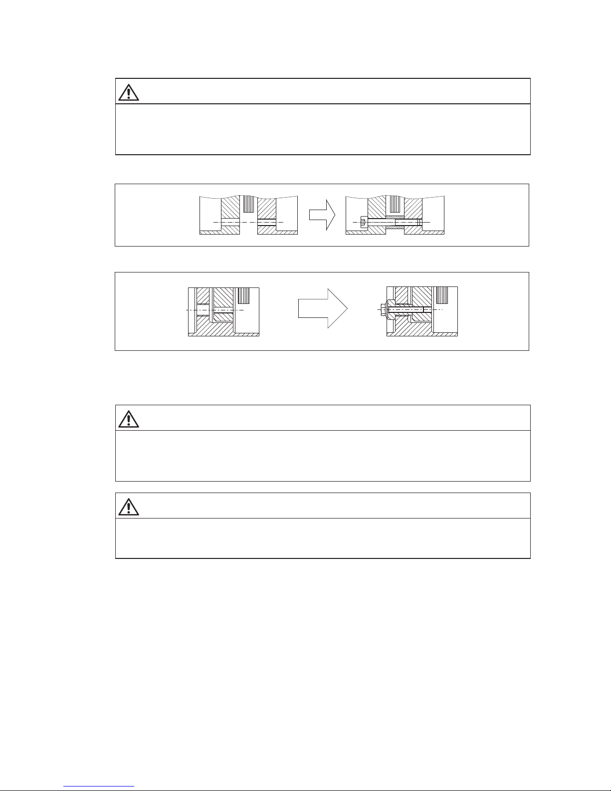
WARNING
Risk of serious injury through flying fragments
Risk of serious injury through flying fragments and/or risk of damage to the coupling.
For running a test with the coupling modules the plate packs must imperatively be fastened with spacer
bushes and cheesehead bolts (see figure 39) or with threaded bushes and collar bolts (see figure 40).
The design of the fastening is shown on the orderspecific drawing of the coupling.
Fig. 39: Test run with fastening with distance bush
Fig. 40: Test run with fastening with threaded bush
The tightening torque of the bolts (see figure 39 or figure 40) can be found on the orderspecific drawing
of the coupling.
WARNING
Risk of serious injury through flying fragments
Risk of serious injury through flying fragments and/or risk of damage to the coupling.
The permissible speed during the test running of coupling modules (see "Fitting data" table on the
orderspecific drawing of the coupling) must not be exceeded.
WARNING
Risk of serious injury through flying fragments
Risk of serious injury through flying fragments and/or risk of damage to the coupling.
The coupling module must be axially secured.
Page 44
44
ARPEX 8706 en
Operating instructions 10/2017
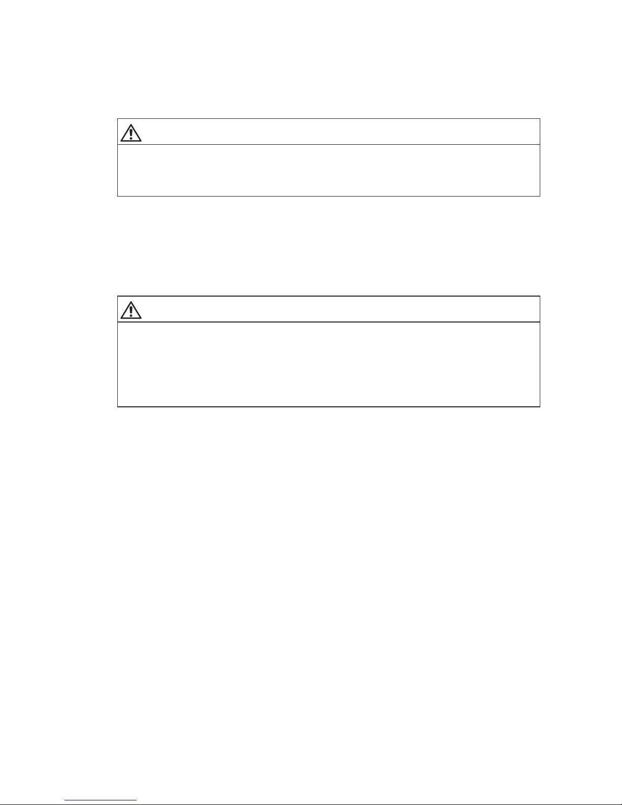
6.10.3 Test run of fitted coupling parts with dummy flange
Observe the safety instructions in section 6.1, "General information on fitting"!
Before starting fitting work the contact surfaces of the dummy flange and the fitted coupling parts must be
carefully cleaned and all preservative agent must be removed. Specifications relating to pulling-on action
can be found on the orderspecific drawing of the coupling.
CAUTION
Risk of corrosion burns through chemical substances
Avoid burns when working with corrosive cleaning agents.
Observe manufacturer’s instructions for handling cleaning agents and solvents.
Wear suitable personal protective equipment (gloves, safety glasses).
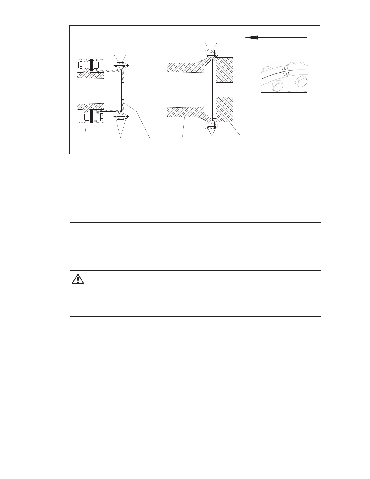
Using the flange screw connection, fit dummy flange, if included in the scope of delivery, onto the fitted
coupling part (e.g. "B" module, "X" module or "M"hub, see figure 41). The dummy flange must be bolted
on so that the identical numbers showing which parts belong with which can be read from one
direction (see mark "AAA" in figure 41). This marking is optional. The mark is dispensed with, if only one
dummy flange has been ordered for two or more identically constructed couplings.
Tighten the screw connection of the flange gradually one after the other to the prescribed tightening torque
(for tightening torque, see orderspecific drawing of the coupling).
WARNING
Risk of serious injury through flying fragments
Risk of serious injury through flying fragments and/or risk of damage to the coupling.
– Locking nuts must only be used three times, to guarantee the locking properties.
– Adhere to specified tightening torques. Observe the instructions relating to cleaning and/or treatment
of the bolts with auxiliary materials.
Page 45
45
ARPEX 8706 en
Operating instructions 10/2017
xy
AAA
AAA
AAA
AAA
134432
Fig. 41: Fitting the dummy flange
(basic drawing BVB and MHM, XVX identical to BVB)
1"B" module 2 "M" hub
3 Dummy flange 4 Screw connection of flange
xy legible from one direction
The screw connections of the flanges (see figure 41) are delivered in separate packing units for each
dummy flange.
NOTICE
Damage to coupling, disruptions
Damage to the coupling and/or disruptions through the incorrect use of screw connections of the flanges.
The screw connections of the flanges have been checked by weight and must always be used or
replaced in sets.
WARNING
Risk of serious injury through flying fragments
Risk of serious injury through flying fragments and/or risk of damage to the coupling.
While running a test of a module with plate pack the plate packs must be fastened as described in item
6.10.2.
Page 46
46
ARPEX 8706 en
Operating instructions 10/2017
Remove the dummy flange after the test run.
Undo the screw connection of the flange (see figure 41) between the fitted coupling part and the dummy
flange and remove the dummy flange.
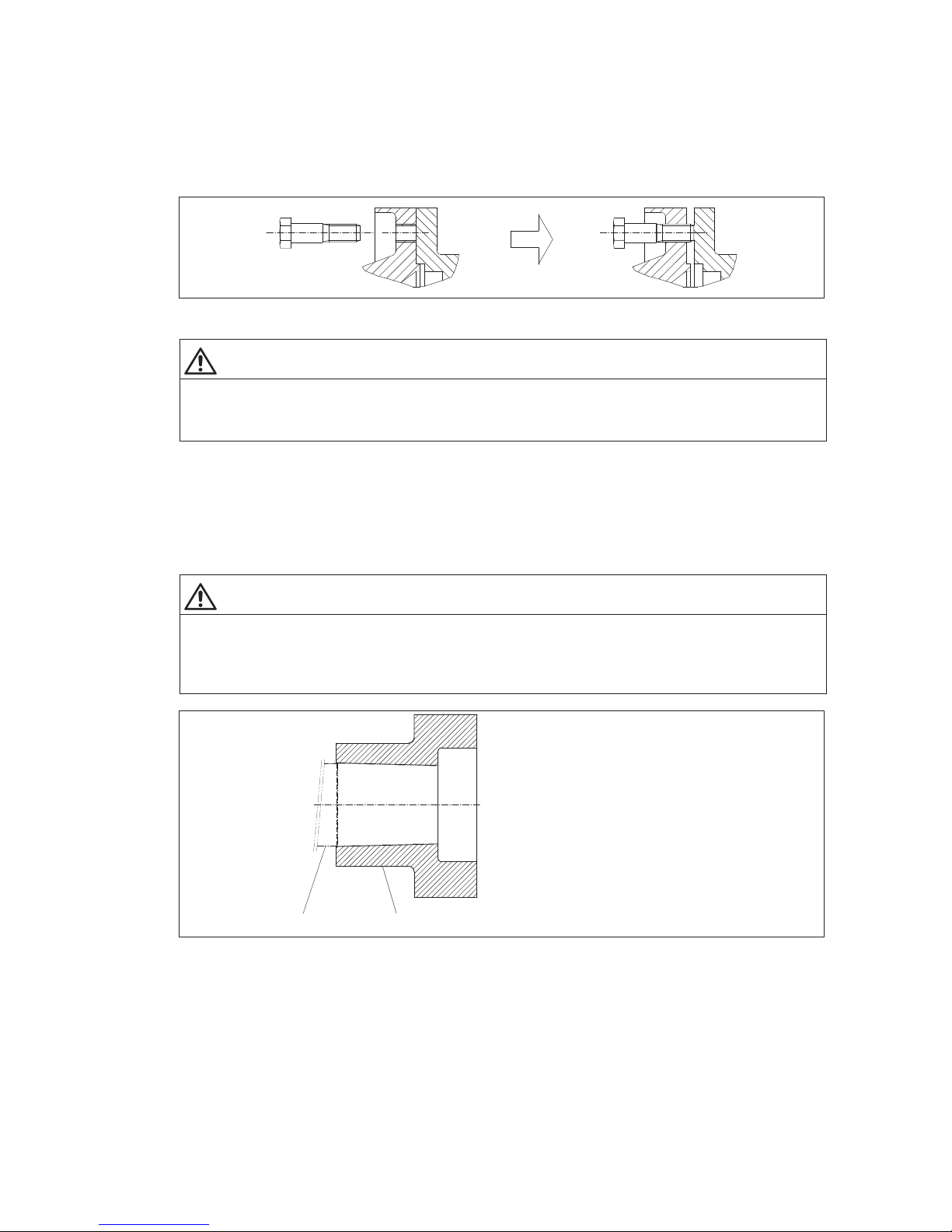
If necessary, using the hexagonsocket closefitting bolts of the flange screw connection (see figure 41),
which must be screwed into the tapped holes provided for in the fitted coupling parts or into the dummy
flanges, press the dummy flange (see figure 41) out of the recess (centering pin) (see figure 42).
Fig. 42: Removing the flange connection dummy flange
WARNING
Risk of serious injury through flying fragments
Risk of serious injury through flying fragments and/or risk of damage to the coupling.
Secure all coupling parts before undoing the screw connection.
6.10.4 Test run of fitted dummies
Observe the safety instructions in section 6.1, "General information on fitting"!
Before starting fitting work the contact surfaces of the dummy and the shaft ends must be carefully cleaned
and all preservative agent must be removed. Specifications relating to pulling-on action can be found on
the orderspecific drawing of the coupling.
CAUTION
Risk of corrosion burns through chemical substances
Avoid burns when working with corrosive cleaning agents.
Observe manufacturer’s instructions for handling cleaning agents and solvents.
Wear suitable personal protective equipment (gloves, safety glasses).
12
Fig. 43: Fitting the dummy
1 Customer’s shaft 2 Dummy
Page 47
47
ARPEX 8706 en
Operating instructions 10/2017
NOTICE
Material damage
Risk of damage to the coupling and the shaft
– The coupling parts must be fitted with the aid of suitable equipment to avoid damaging the shaft
bearings through axial joining forces. Use suitable lifting gear.
– The information specified on the dimensioned drawing relating to the pullingon path must be
observed.
– Observe the orderrelated entries on the drawing of the coupling relating to the joining temperature.
WARNING
Danger of burns
Serious injury through burns on hot surfaces (> 55 °C) possible.
Wear suitable protective gloves and protective clothing.
WARNING
Risk of serious injury through flying fragments
Risk of serious injury through flying fragments and/or risk of damage to the coupling.
The coupling module must be axially secured.
Remove the dummy flange after the test run.
NOTICE
Damage to the coupling, damage to other components
Damage to the coupling and the shaft through incorrect pulling off.
The coupling parts must be pulled off the shaft end using suitable devices.
Use suitable lifting gear.
WARNING
Risk of serious injury through flying fragments
Risk of serious injury through falling coupling parts and/or flying fragments and/or risk of damage to the
coupling.
– The coupling module must be axially secured.
– Observe the permissible demounting pressure and temperature values specified on the
orderspecific drawing of the coupling.
Page 48
48
ARPEX 8706 en
Operating instructions 10/2017
6.11 Demounting the intermediate unit
6.11.1 Procedure applying to modules with distance bush
Observe the safety instructions in section 6.1, "General information on fitting"!
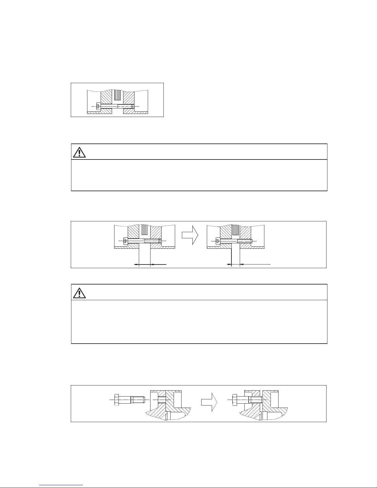
Reinsert the cheesehead bolts of the fastening (see figure 44). The design of the fastening is shown on
the orderspecific drawing of the coupling. Make sure that the cheesehead bolts are only inserted
loosely without being tightened.
Fig. 44: Inserting the cheesehead bolts of the fastening
Undo the screw connection of the flange (see figs. 6 to 16) and remove them.
WARNING
Serious injury
Risk of serious injury through falling coupling parts and/or flying fragments and/or risk of damage to the
coupling.
Secure all coupling parts against falling before undoing the screw connection.
Tighten the cheesehead bolts of the fastening, so that the plate packs are axially clinched to a dimension
of S1
fitting
(see table "Fitting data " on the orderspecific drawing of the coupling) and the intermediate
unit can be taken off (see figure 45).
S1 S1
fitting
Fig. 45: Illustration S1
fitting
WARNING
Risk of serious injury through flying fragments
Risk of serious injury through flying fragments and/or risk of damage to the coupling through the plate
packs being too tightly clinched during the fitting procedure.
The plate packs may be clinched to a maximum dimension of S1
fitting
(see figure 45) for fitting and
disassembly. The value in the table "Fitting data" on the orderspecific drawing of the coupling must be
adhered to.
If necessary, also shift the shaft ends of the machines to be joined together axially.
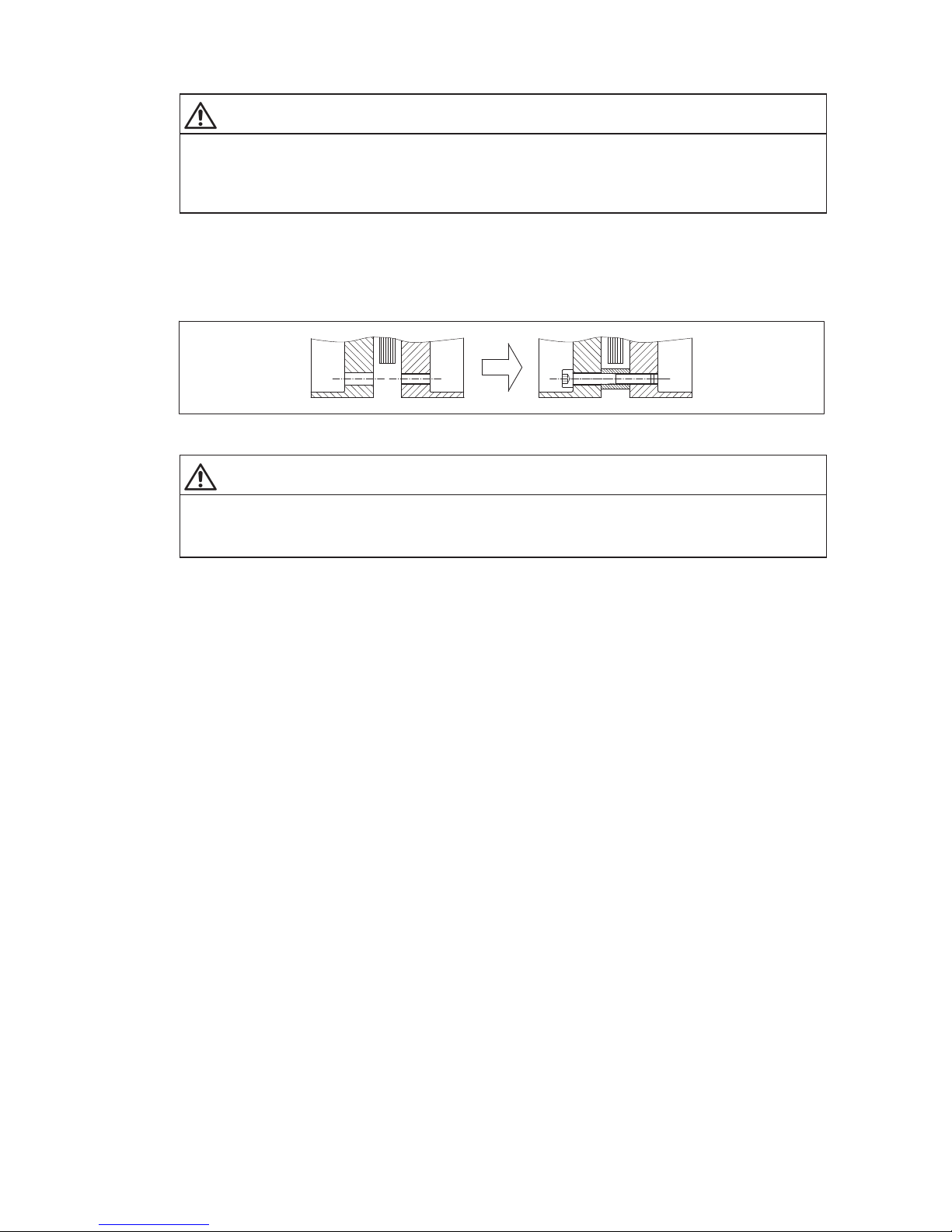
If necessary, using the hexagonsocket fitting bolts of the flange screw connection (see figures 6 to 16),
which must be screwed into the tapped holes provided for in the coupling parts, press the intermediate unit
(see figs. 6 to 16) out of the recess (centering pin) (see figure 46).
Fig. 46: Demounting the flange connection
Page 49
49
ARPEX 8706 en
Operating instructions 10/2017
Remove the intermediate unit (see figs. 6 to 16).
WARNING
Serious injury
Risk of serious injury through falling coupling parts and/or flying fragments and/or risk of damage to the
coupling.
Secure all coupling parts against falling before undoing the screw connection.
After demounting the cheesehead bolts of the fastening (see figure 47) must imperatively be undone
again, so that the plate pack is detensioned and the cheesehead bolts remain only loosely screwed in.
Remove the cheesehead bolts (see figure 47) for transport purposes, so that the distance bushes
(see figure 47) can be inserted again. After this, insert the cheesehead bolts again and tighten them
handtight.
Fig. 47: Inserting the fastening
WARNING
Serious injury
Risk of serious injury through flying fragments and/or risk of damage to the coupling.
Fit the transport lock of the plate pack before transport.
Page 50
50
ARPEX 8706 en
Operating instructions 10/2017
6.11.2 Procedure applying to modules with threaded bush
Observe the safety instructions in section 6.1, "General information on fitting"!
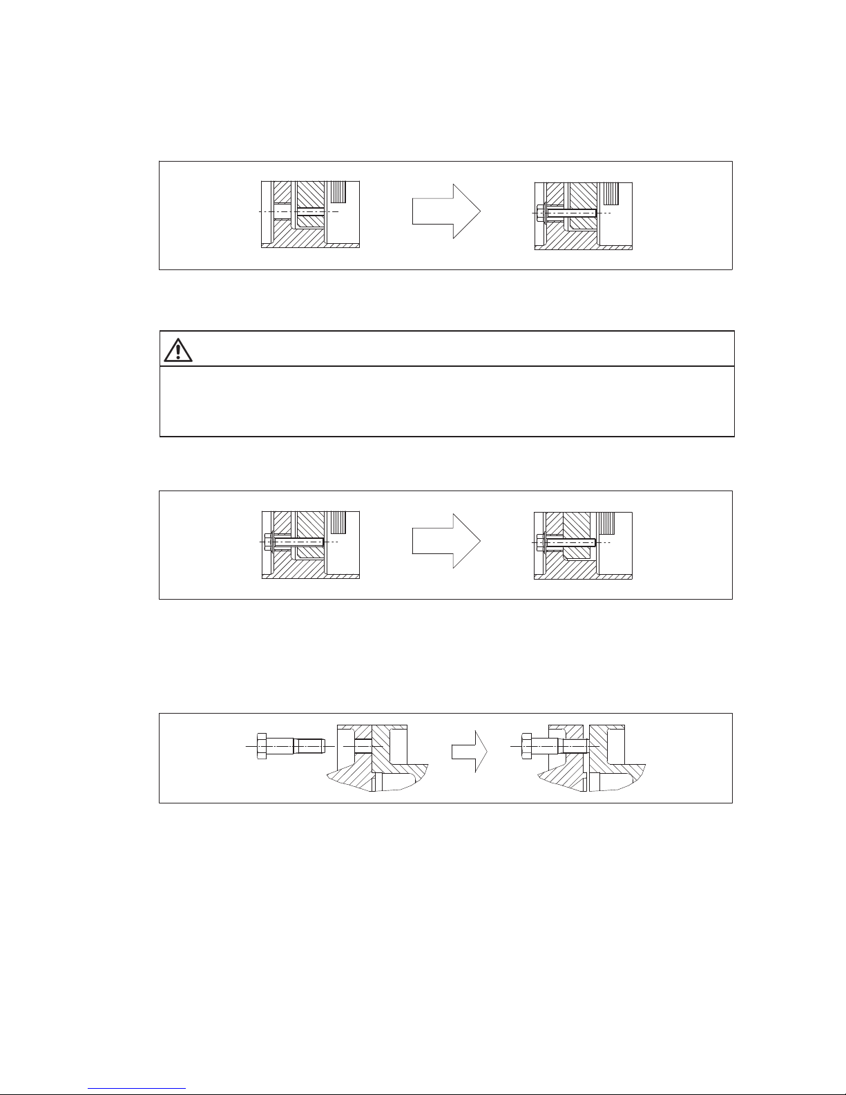
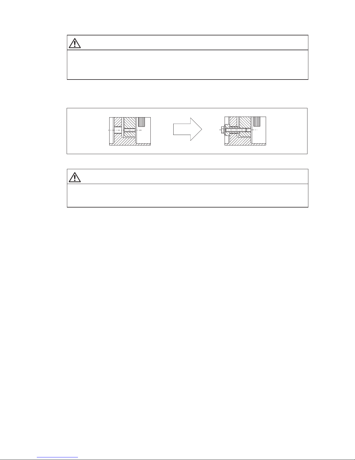
Reinsert the collar bolts of the fastening (see figure 48) again. The design of the fastening is shown on the
orderspecific drawing of the coupling. Make sure that the collar bolts are only inserted loosely without
being tightened.
Fig. 48: Inserting the collar bolts of the fastening
Undo the screw connection of the flange (see figs. 6 to 16) and remove them.
WARNING
Serious injury
Risk of serious injury through falling coupling parts and/or flying fragments and/or risk of damage to the
coupling.
Secure all coupling parts against falling before undoing the screw connection.
Tighten the collar bolts of the fastening as far as the coupling flanges will go (see figure 49), so that the plate
packs are clinched axially and the intermediate unit can be removed.
Fig. 49: Tightening the collar bolt
If necessary, also shift the shaft ends of the machines to be joined together axially.
If necessary, using the hexagonsocket fitting bolts of the flange screw connection (see figures 6 to 16),
which must be screwed into the tapped holes provided for in the coupling parts, press the intermediate unit
(see figs. 6 to 16) out of the recess (centering pin) (see figure 50).
Fig. 50: Demounting the flange connection
Page 51
51
ARPEX 8706 en
Operating instructions 10/2017
Remove the intermediate unit (see figs. 6 to 16).
WARNING
Serious injury
Risk of serious injury through falling coupling parts and/or flying fragments and/or risk of damage to the
coupling.
Secure all coupling parts against falling before undoing the screw connection.
After demounting the collar bolts of the fastening (see figure 49) must imperatively be undone again, so
that the plate pack is detensioned and the collar bolts remain only loosely screwed in. For transporting
remove the collar bolts (see figure 51), fit the threaded bush and reinsert the collar bolt and fit handtight.
Fig. 51: Inserting the fastening
WARNING
Serious injury
Risk of serious injury through flying fragments and/or risk of damage to the coupling.
Fit the transport lock of the plate pack before transport.
Page 52
52
ARPEX 8706 en
Operating instructions 10/2017
6.11.3 Demounting the fitted coupling modules or components
Observe the safety instructions in section 6.1, "General information on fitting"!
Pull the "B", "X" modules and/or "M" hubs (see e.g. figs. 6 to 16), if possible with the aid of demounting
devices, off the shaft ends of the machines to be joined together.
WARNING
WARNING
Risk of serious injury through flying fragments
Risk of serious injury through falling coupling parts and/or flying fragments and/or risk of damage to the
coupling.
– The coupling module must be axially secured.
– Observe the permissible demounting pressure and temperature values specified on the
orderspecific drawing of the coupling.
WARNING
Danger of burns
Serious injury through burns on hot surfaces (> 55 °C) possible.
Wear suitable protective gloves and protective clothing.
In the case of "F" modules (see figs. 6 to 16) undo the screw connection to the customer’s flange or the
screw connection to the "F" flange, and demount the "F" module.
In the case of "F" flanges (see figs. 6 to 16) undo the screw connection to the customer’s flange and
demount the flange.
WARNING
Serious injury
Risk of serious injury through falling coupling parts and/or flying fragments and/or risk of damage to the
coupling.
Secure all coupling parts against falling before undoing the screw connection.
Page 53
53
ARPEX 8706 en
Operating instructions 10/2017
7. Startup
Observe the instructions in section 3, "Safety instructions"!
7.1 Procedure before startup
The design of the fastening is shown on the orderspecific drawing of the coupling.
WARNING
Serious injury
Risk of serious injury through flying fragments and/or risk of damage to the coupling.
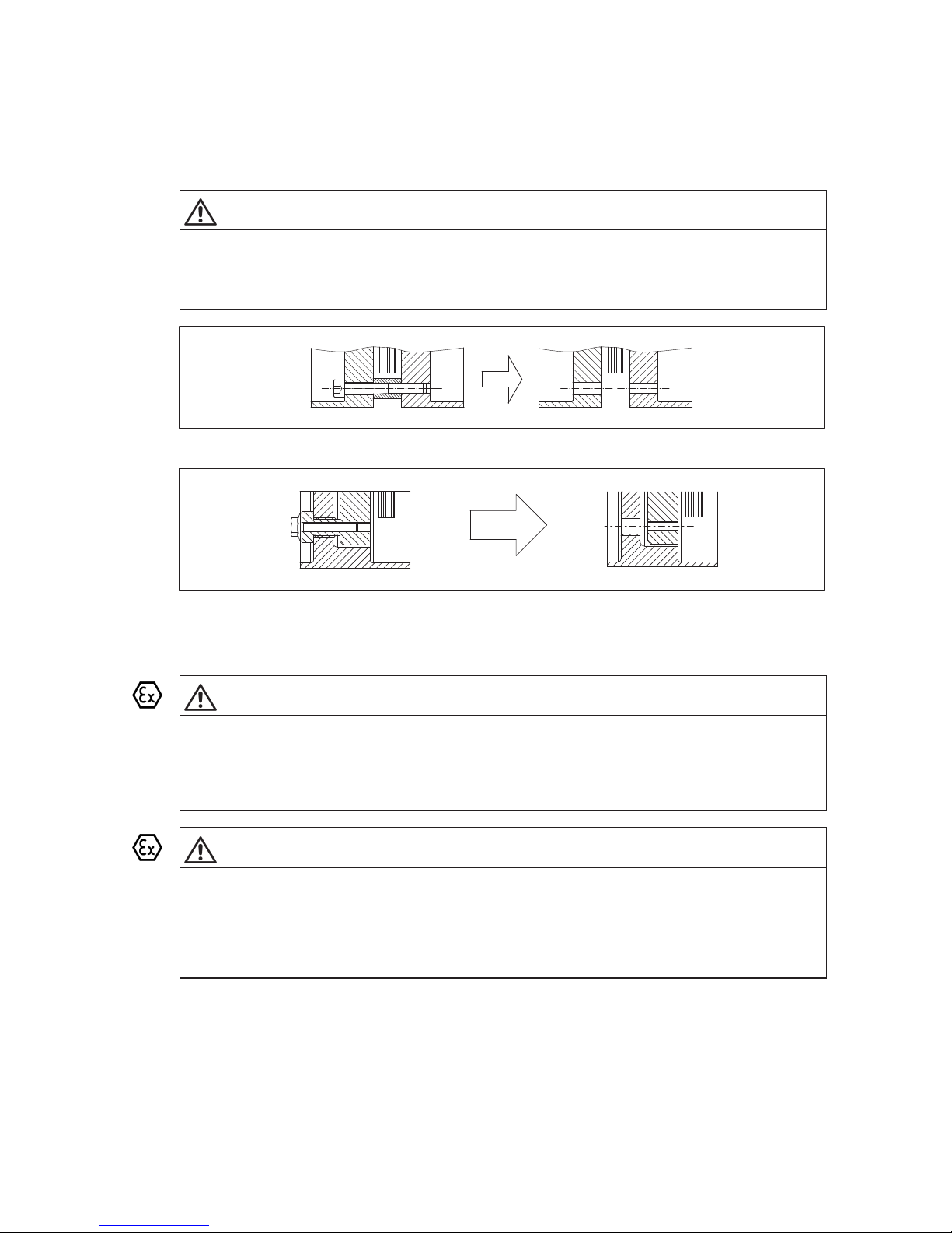
Before startup, remove the fastening of the plate packs (distance bush, see figure 52 / threaded bush,
see figure 53 and cheesehead bolt).
Fig. 52: Removing the fastening with distance bush
Fig. 53: Removing the fastening in case of threaded bush
Before startup, the tightening torque of the flange bolts must be checked and, if necessary, the flange bolts
must be retightened.
DANGER
Danger of explosion
Risk of explosion when operating in potentially explosive areas through damage.
Damaged coupling modules and coupling parts are potential explosion hazards.
Use only undamaged coupling components. Operating the coupling with damaged coupling parts is not
permitted in potentially explosive environments in accordance with Directive 2014/34/EU.
DANGER
Danger of explosion
Risk of explosion when operating in potentially explosive areas.
Incorrect changes made to the coupling will create ignition sources.
Any changes on the part of the user are not permitted. This applies equally to safety features designed
to prevent accidental contact. For the use in potentially explosive environments the protective
equipment must comply at least with type of protection IP2X.
Page 54
54
ARPEX 8706 en
Operating instructions 10/2017
WARNING
Serious injury
Risk of serious injury through flying fragments and/or risk of damage to the coupling.
The module has already been fully assembled at the factory. The plate packs must not be demounted
or retightened.
The alignment and the distance dimension on the plate pack (see item 6.9) must also be checked and,
if necessary, adjusted.
WARNING
Risk of injury
Risk of injury through accidental contact with rotating components.
The coupling must be fitted with suitable safeguards to prevent any accidental contact. The operation
of the coupling must not be impaired by the safeguard. This also applies to test runs and when checking
the direction of rotation.
Page 55
55
ARPEX 8706 en
Operating instructions 10/2017
8. Operation
Observe the instructions in section 3, "Safety instructions"!
8.1 General operating data
During operation of the coupling watch for:
• Changes in running noise
• Sudden vibrations
WARNING
Serious injury
Rotating components may cause injury during work on the still rotating coupling.
All work on the coupling must be carried out only when it is at a standstill. Secure the drive unit to prevent
unintentional switchon. A notice should be attached to the ON switch stating clearly that work on the
coupling is in progress. The relevant accident prevention regulations at the place of installation apply as
well.
WARNING
Risk of serious injury through flying fragments
Risk of serious injury through flying fragments and/or risk of damage to the coupling.
If any malfunctions or changes are noticed during operation, the drive assembly must be switched off
at once.
Page 56
56
ARPEX 8706 en
Operating instructions 10/2017
9. Faults, causes and remedy
Observe the instructions in section 3, "Safety instructions"!
9.1 General
The following irregularities can serve as a guide for fault tracing.
Where the system is a complex one, all component units must be included when tracing faults.
The coupling must run with little noise and vibration in all operating phases. Irregular behaviour must be
treated as a fault requiring immediate remedy.
WARNING
Risk of serious injury through flying fragments
Risk of serious injury through flying fragments and/or risk of damage to the coupling.
– Any changes on the part of the user are not permitted. This applies equally to safety features designed
to prevent accidental contact.
– The coupling is designed only for the application specified in the order. Other operating conditions are
regarded as incorrect and must be contractually agreed. For any damage resulting therefrom only the
user or operator of the machine or plant is responsible.
WARNING
Risk of serious injury through flying fragments
Risk of serious injury through flying fragments and/or risk of damage to the coupling through use of
defective spare parts.
Flender guarantees only the genuine spare parts supplied by Flender.
Nongenuine spare parts have not been tested or approved by Flender. Nongenuine spare parts may
alter technical characteristics of the coupling, thereby posing an active or passive risk to safety.
Flender will assume no liability or guarantee for damage caused by spare parts not supplied by Flender.
The same applies to any accessories not supplied by Flender.
Page 57
57
ARPEX 8706 en
Operating instructions 10/2017
WARNING
Risk of serious injury through flying fragments
Risk of serious injury through flying fragments and/or risk of damage to the coupling.
If any malfunctions or changes are noticed during operation, the drive assembly must be switched off
at once.
Note
Determine the cause of the fault, using the troubleshooting table. If the cause cannot be identified and/or
the unit repaired with the facilities available, you are advised to contact one of our customerservice
offices for specialist assistance.
WARNING
Serious injury
Risk of serious injury or risk of damage to the coupling.
The relevant safety and environmental regulations must be complied with.
Note
Depending on national regulations, coupling and clutch components have to be disposed of separately
or separated for recycling.
Page 58
58
ARPEX 8706 en
Operating instructions 10/2017
9.2 Possible faults
Table 2: Faults, causes and remedy
Faults Causes Remedy
Sudden changes in the noise
level and/or sudden
vibrations.
Change in alignment. Stop the system,
and, if necessary, rectify the cause of the
alignment hange
(e.g. tighten loose foundation bolts).
Perform a visual check (procedure as
described in section 10).
Plate breakage, torque
transmission via bolts of the
plate-pack screw connection.
Stop the installation.
Demount the coupling.
Despatch the coupling to the manufacturer
for being replaced or, if necessary, repaired,
and re-balanced.
Occurrence of vibrations. Incorrect fitting of the
coupling; non-observance
of component markings for
assembly balancing (see
item 6.7).
Stop the installation.
Check component markings in accordance
with item 6.7 and, if necessary, demount the
coupling and recify the position of the
components.
Perform a visual check (procedure as
described in section 10).
WARNING
Risk of serious injury through flying fragments
Risk of serious injury through flying fragments and/or risk of damage to the coupling.
Only undamaged coupling parts must be used. In particular the teeth, holes, screw threads and joining
and sealing surfaces must not be damaged.
DANGER
Danger of explosion
Risk of explosion when operating in potentially explosive areas through damage.
Damaged coupling modules and coupling parts are potential explosion hazards.
Use only undamaged coupling components. Operating the coupling with damaged coupling parts is not
permitted in potentially explosive environments in accordance with Directive 2014/34/EU.
Page 59
59
ARPEX 8706 en
Operating instructions 10/2017
9.3 Incorrect use
Experience has shown that the following faults can result in incorrect use of the ARPEX coupling. In
addition to observing the other instructions in this manual, care must therefore be taken to avoid these
faults.
Directive 2014/34/EU requires the manufacturer and user to exercise especial care.
WARNING
Risk of serious injury through flying fragments
Risk of serious injury through flying fragments and/or risk of damage to the coupling.
The coupling is designed only for the application specified in the order. Other operating conditions are
regarded as incorrect and must be contractually agreed. For any damage resulting therefrom only the
user or operator of the machine or plant is responsible.
DANGER
Danger of explosion
Risk of explosion when operating in potentially explosive areas through damage.
Damaged coupling modules and coupling parts are potential explosion hazards.
Use only undamaged coupling components. Operating the coupling with damaged coupling parts is not
permitted in potentially explosive environments in accordance with Directive 2014/34/EU.
9.3.1 Possible faults when selecting the coupling and/or coupling size
─ Important information for describing the drive and the environment are not communicated.
─ System torque too high.
─ System speed too high.
─ Application factor not correctly selected.
─ Chemically aggressive environment is not being taken into consideration.
─ The temperature in the direct vicinity of the coupling is beyond the permissible range.
─ The transmission capacity of the shafthub connection is not appropriate to the operating conditions.
─ Fitting and/or operational misalignment values of the shaft ends of the machines to be coupled are too
high.
Page 60

60
ARPEX 8706 en
Operating instructions 10/2017
9.3.2 Possible faults when fitting the coupling
─ Components with transport or other damage are being fitted.
─ When fitting coupling parts in a heated condition, these components are being excessively heated.
─ The shaft diameter is beyond the specified tolerance range.
─ Coupling parts are interchanged during fitting work.
─ Nonobservance of component markings for assembly balancing (see item 6.7) while the coupling is
fitted.
─ Specified tightening torques are not being adhered to.
─ Alignment and/or shaftmisalignment values do not match the specifications on the orderspecific
drawing of the coupling.
─ The coupling protection used is not suitable for operation within the meaning of the
explosionprotection requirements and/or in accordance with Directive 2014/34/EU.
─ Operating conditions are being changed without authorisation.
9.3.3 Possible faults in the maintenance of the plant
─ Maintenance intervals are not being adhered to.
─ Impermissible shaft misalignments occur, which are caused by the coupled units settling and were not
taken into consideration when designing the coupling.
─ Leakage in the vicinity of the coupling is not being identified and as a result chemically aggressive
media are damaging the coupling.
Page 61
61
ARPEX 8706 en
Operating instructions 10/2017
10. Maintenance and repair
Observe the instructions in section 3, "Safety instructions"!
DANGER
Danger of explosion
Risk of explosion when operating in potentially explosive areas through damage.
Damaged coupling modules and coupling parts are potential explosion hazards.
Use only undamaged coupling components. Operating the coupling with damaged coupling parts is not
permitted in potentially explosive environments in accordance with Directive 2014/34/EU.
WARNING
Serious injury
Rotating components may cause injury during work on the still rotating coupling.
All work on the coupling must be carried out only when it is at a standstill. Secure the drive unit to prevent
unintentional switchon. A notice should be attached to the ON switch stating clearly that work on the
coupling is in progress. The relevant accident prevention regulations at the place of installation apply as
well.
10.1 General
ARPEX couplings do not require maintenance; however, they should be visually inspected during
regular system maintenance inspections at least once a year. Especial attention should be given to the
condition of the plate packs. If individual plates or several plates are broken, the plate pack affected must
be replaced (see item 10.2).
No further maintenance work is necessary.
10.2 Replacing plate packs
If the plate packs must be replaced, it is required to return the coupling to the manufacturer for repair and
rebalancing.
WARNING
Serious injury
Risk of serious injury through flying fragments and/or risk of damage to the coupling.
The module has already been fully assembled at the factory. The plate packs must not be demounted
or retightened.
10.3 Replacing screw connections of the flanges
NOTICE
Damage to the coupling
Damage to the coupling and/or disruptions through the incorrect use of screw connections of the flanges.
The screw connections of the flanges have been checked by weight and must always be used or
replaced in sets.
Page 62
62
ARPEX 8706 en
Operating instructions 10/2017
11. Spare parts, customerservice
By stocking the most important spare parts on site you can ensure that the coupling is ready for use.
To order spare parts, refer to the spareparts list.
We guarantee only the genuine spare parts supplied by us.
WARNING
Risk of serious injury through flying fragments
Risk of serious injury through flying fragments and/or risk of damage to the coupling through use of
defective spare parts.
Flender guarantees only the genuine spare parts supplied by Flender.
Nongenuine spare parts have not been tested or approved by Flender. Nongenuine spare parts may
alter technical characteristics of the coupling, thereby posing an active or passive risk to safety.
Flender will assume no liability or guarantee for damage caused by spare parts not supplied by Flender.
The same applies to any accessories not supplied by Flender.
Please note that certain components often have special production and supply specifications and that we
supply you with spare parts which comply fully with the current state of technical development as well as
current legislation.
When ordering spare parts, always state the following:
─ Quantity
─ Designation
─ Size
─ Number of the drawing of the coupling
─ Position of the spare part in the spareparts list
11.1 Spareparts and customerservice addresses
When ordering spare parts or requesting a service specialist, please contact Flender first (see section 2).
Page 63

63
ARPEX 8706 en
Operating instructions 10/2017
12. Declarations
12.1 EU declaration of conformity
EU declaration of conformity
The manufacturer, Flender GmbH, 46395 Bocholt, Germany, declares that the equipment described in these
operating instructions:
FLENDER COUPLINGS ARPEX®
ART, ARE
is in conformity with Article 1 and Article 13, Paragraph 1 b) ii) of Directive 2014/34/EU and complies with the
requirements of Directive 2014/34/EU and the following standards:
EN 1127-1 : 2011
EN 13463‐1 : 2009
EN 13463‐5 : 2011
EN 1710 : 2008
This declaration of conformity is issued under the sole responsibility of the manufacturer.
The object of the declaration described above is in conformity with the relevant Union harmonisation
legislation:
Directive 2014/34/EU OJ L 96, 29.03.2014, p.309-356 (effective from 20.04.2016, 00:00 a.m.)
Directive 94/9/EC OJ L 100, 19.04.1994, p.1-29 (effective until 19.04.2016, 12.00 p.m.)
The technical documentation has been delivered to the body named below:
DEKRA EXAM GmbH, 44727 Bochum, Germany, code number: 0158.
Bocholt, 2017‐10‐01
Felix Henseler, Head of PD MD AP
Bocholt, 2017‐10‐01
Thomas Tebrügge / Head of PD MD AP COU BA
Page 64

FLENDER COUPLINGS
ARPEX
Operating instructions 8706 en
Edition 10/2017
Flender GmbH
Alfred-Flender-Straße 77
46395 Bocholt
GERMANY
- - - - - - - - - - - - - - - - - - - - - - - - - - - - - - - - - - - - - - - - - - - - - - - - - - - - - - - - - - - - - -
- - - - - - - - - - - - - - - - - - - - - - - - - - - - - - - - - - - - - - - - - - - - - - - - - - - - - - - - - - - - - -
flender.com
 Loading...