

Page 1
BETRIEBSANLEITUNG
Operating Instructions . Instructions
de service. Handleiding' Vejledning .
Istruzioni per la manuteniione
FLEISCBMANN
DieModellbahnder Profis
N
-
---
«piccolo»
----
Gerades Gleis mit eingebautem Schaltkontakt
Das gerade Gleis mit eingebautem Schaltkontakt hat eine Länge von 55,5 mm. Dies entspricht
der Länge eines geraden Gleises 9103.
Der eingebaute Schaltkontakt ist ein Momentschalter für max. 0,8 Schaltstrom, bei dem die
Schaltwechselspannung 12 - 14 V unabhängig von der Fahrspannung geführt wird, Die
Schaltimpulse werden durch den Schaltmagneten 9426/9427 ausgelöst, der sowohl am Boden
von Loks als auch von Wagen befestigt werden kann.
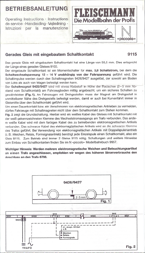
Der-Schaltmagnon-'9426f942rwirdoniretwas' Klebstoff"i" Hölle oet RatlacTIse(2'~5ITIm-""A1:'5=-~
stand vom Schaltkontakt) am Fahrzeugboden mittig angebracht, um ein sicheres Schalten zu
gewährleisten (Fig.1). An Fahrzeugen mit Drehgestellen muss der Magnet am Drehgestell in
unmittelbarer Nähe des Drehgestells befestigt werden, damit er auch bei Kurvenfahrt immer in
Gleismitte über den Schaltkontakt geführt wird"
Um einen Dauerkontakt bzw. ein Verschmorenvon elektromagnetischen Antrieben zu vermeiden,
dürfen Fahrzeugemit Schaltmagneten nicht über dem Schaltkontakt zum Stehen kommen.
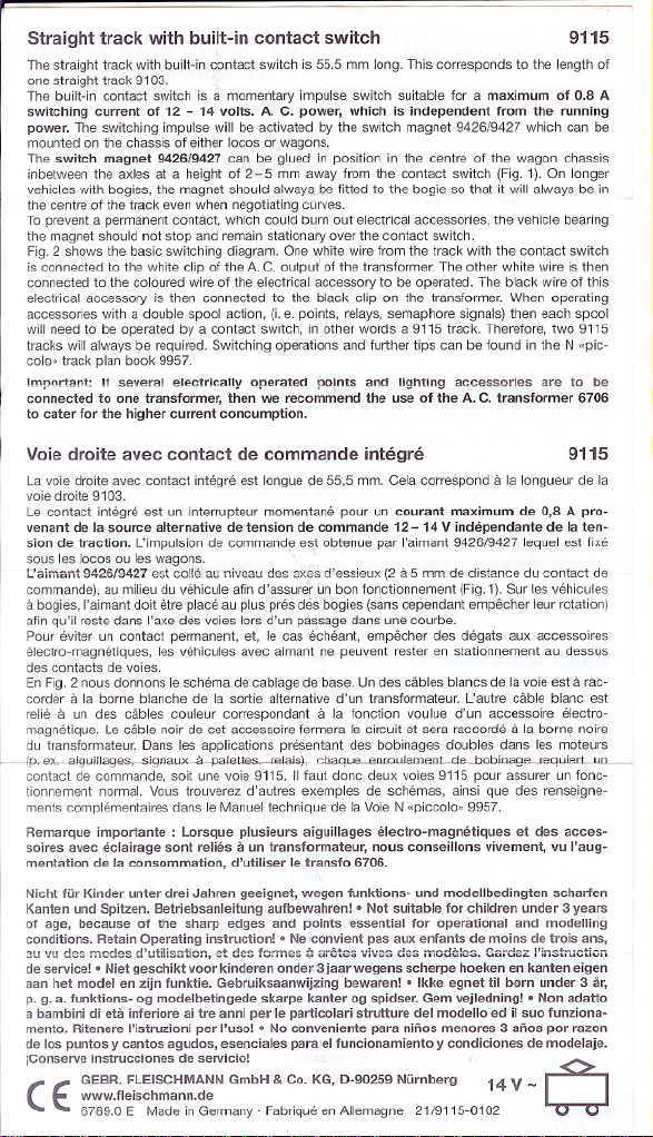
Fig. 2 zeigt die Grundschaltung. Hierbei wird ein weißes Kabel des Gleises mit Schaltkontakt mit
der weiß gekennzeichneten Klemme des Wechselstromausgangs am Trafo verbunden. Das ande-
re weiße Kabel wird mit dem farbigen Kabel des zu betreibenden elektromagnetischen Artikels
verbunden. Das schwarze Kabel des elektromag[~tischen Artikels wird an die schwarze Klemme
des Trafos geführt. Bei Verwendung von elektromagnetischen Artikeln mit Doppelspulenantrieb
(z,B. Weichen, Relais, Formsignalantrieb) benötigt jede Einzelspule einen Schaltkontakt, also ein
Gleis 9115. Zum Betrieb sind immer 2 Gleise 9115 nötig. Schaltungen und weitere Hinweise
zum Einbau von Schaltkontakten finden Sie im N "piccolo» Modellbahnbuch 9957.
Wichtiger Hinweis: Werden mehrere elektromagnetische Weichen und Beleuchtungsartikel
an einen Trafo angeschlossen, empfehlen wir wegen des höheren Stromverbrauchs den
Anschluss an den Trafo 6706.
9426/9427
9115
.0101
9400
9100 9100
I,
='\."
TRAFO
."".
_,iI-\ ,-<,.
cl,
9101
Fig.2
Page 2
Straight track with built-in contact switch
The straight track with built-in contact switch is 55.5 mm lang. This corresponds to the length 01
one straight track 9103. ..
The built-in contac1 switch is amomentary impulse switch suitable lor a maximum of 0.8 A
switching current of 12 - 14 volts. A. C. power, which is independent Iram the running
power. The switching impulse will be activated by the switch magnet 9426/9427 which can be
mounted on the chassis 01either locos or wagons.
The switch magnet 9426/9427 can be glued in position in the centre 01 the wagon chassis
inbetween the axles at a height 01 2-5 mm away lrom the contact switch (Fig. 1). On langer
vehicles with bogies. the magnet should always be litted to 1he bogie so that it will always be in
the centre 01the track even when negotiating tÜrves.
Ta preventa permanent contact, which could burn out electrical accessories, the vehicle bearing
the magnet should not stop and remain stationa'", over the contact switch.
Fig. 2 shows the basic switching diagram. One white wire Irom the track with the contact switch
is connected to the white clip 01the A.C. output 01the translormer. The other white wire is then
connected to the coloured wire of the electrical accessory to be operated. The black wire 01this
electrical accessory is then connected to the black clip on the translormer. When operating
accessories with a double spool action, (I.e. points, relays, semaphore signals) then each spool
will need to be operated by a contact switch, in other words a 9115 track. Therelore, two 9115
tracks will always be required. Switching operations and lurther tips can be lound in the N "pic-
colo.. track plan book 9957.
Imporlan1: If several electricalty operated points and lighting accessories are to be
connected to one transfarmer, then we recammend the use of the A. C. transformer 6706
to cater for the higher current concumption.
9115
Voie droite avec contact de commande integre
La voie droite avec contact integre est longue de 55,5 mm. Cela correspond a la longueur de la
voie draite 9103.
Le contact integre est un interrupteur momentane pour un courant maximum de 0,8 A pro-
venant de la source alternative de tension de commande 12 - 14 V independante de la ten-
sion de traction. L'impulsion de commande est obtenue par I'aimant 9426/9427 lequel est lixe
sous les locos ou les wagons. '
I:aiman~ 9426/9427 est colle au niveau-des a)(&sd'essieux (2 a 5 mm de distance du contact de
commande), au milieudu vehicule alin d'assuretun bon lonctionnement (Fig. 1).Sur les vehicules
a bogies, I'aimantdoit etre place auplus pres des bogies (sanscependant empecher leur rotation)
alin qu'iI reste dans I'axe des voies lors d'un passage dans une courbe.
Pour eviter un contact permanent, et, le cas e'eheant, empecher des degats aux accessoires
electro-magnetiques, les vehicules avec aimant ne peuvent rester en stationnement au dessus
des contacts de voies.
En Fig. 2 nous dannans leschema de cablage de base. Un des cables blancs de la voieest a rac-
corder a la borne blanche de la sortie alternative d'un translormateur. L'autre cable blanc est
relie a un des cables couleur correspondant a la lonction voulue d'un accessoire electro-
magnetique. Le cable noir de cet accessoire lerrnera le circuit et sera raccorde a la borne noire
du translormateur. Dans les applications presentant des bobinages doubles dans les moteurs
l (p..ex.-aiguiJlages,--Signaux-"-pa1ettes, <eJajs).._oh21' 'Q Qnm, ,IQmpnl rlp--bobioagp-.r.equieri.JlIL-
contact de commande, soit une voie 9115. 11faut donc deux voies 9115 pour assurer un lonc-
tionnement normal. Vous trouverez d'autres exemples de schemas, ainsi que des renseigne-
ments complementaires dans le Manuel technique de la Voie N "piccolo.. 9957.
Remarque importante: Lorsque plusieurs aiguillages elec1ro-magnetiques et des acces-
soires avec eclairage sont relies a un transfarmateur, nous conseiltons vivement, vu I'aug-
mentation de la consommation, d'utiliser 'e transfo 6706.
Nicht für Kinder unter drei Jahren geeignet, wegen funktions- und modelt bedingten scharfen
Kanten und Spitzen. Betriebsanleitung aufbewahren! .Not suitable for children under 3 years
of age, because of the sharp edges and points essential for operational and modelling
conditions. Retain Operating instruction! .Ne 'convient pas aux enfants de moins de trois ans,
au vu d2s modes d'utilisa1i"n, ct des form2s ;: aretes vives d2s modeles. Gardez I'instructkm
de service! .Niet geschikt voor kinderen onde.3 jaar wegens scherpe hoeken en kanten eigen
aan het model en zijn funktie. Gebruiksaanwijzing bewaren! .Ikke egnet til born under 3 är,
p. g. a. funktions- og modelbetingede skarpe kanter og spidser. Gem vejledning! .Non adatto
a bambini di eta inferiore ai tre anni per le particolari strutture dei modello ed il suo funziona-
mento. Ritenere I'istruzioni per I'uso! . No conveniente para ninos menores 3 anos por razan
de los puntos y cantos agudos, esenciales para 'ei funcionamiento y condiciones de modelaje.
jConserve instrucciones de servicio!
L:: GEBR. FLEISCHMANN GmbH & CO.KG, D-90259 Nürnberg 14 V -
~ www.fleischmann.de
(
6789.0 E Made inGermany . Fabrique enAllemagne 21/9115-0102
9115
W
 Loading...