

Fleetwood American Eagle 2006, American Tradition 2006, American Heritage 2006 Owner's Manual

Driven
to
Explore
ANI
-
-
-
FI
ICAN
R I
(
a n
2.00b
©2005 by Fleetwood Enterprises, Inc. All rights reserved. No part
of
this publication may be reproduced or
transmitted in any form or by any means, electronic or mechanical, including photocopying, recording, or by any
information storage or retrieval system without written permission from Fleetwood Enterprises, Inc.
IMPORTANT -
PLEASE READ: Product information, photography and illustrations included in this manual were as
accurate as possible at the time
of
publication. Materials, design, and specifications are subject to change without
notice. Fleetwood has designed its recreational vehicles for a variety
of
customer uses. Each vehicle features optimal
seating, sleeping, storage, and fluid capacities. The user is responsible for selecting the proper combination
of
loads
(Le.
occupants, equipment, fluids, cargo, etc.)
to
ensure that the vehicle's weight capacities are not exceeded.
Manufacturing subsidiaries
of
Fleetwood Enterprises, Inc. build the following motor homes and travel trailers:
American
Eagle'
American
Heritage'
American Tradition'
Bounder'
Bounder
Diesel·
Discovery·
Excursion'
Expedition'
Fiesta·
Flair'
Gearbox'
Jamboree'
Mallard'
Orbit·
Pace
Arrow'
Park Trailer'
Pegasus'
Pioneer·
Pride'
Providence' Prowler· Revolution· Revolution LE • Southwind •
Storm'
Terra'
Terry·
Tioga'
1l.iumph •
Wilderness

This page intentionally blank.
,\
:
:1
INTRODUCTION .
....................
. 01·1
Inspect and Maintain
...................
01·2
Planning
and Preparation
................
01-2
Owner's Information Package
............
01-2
Chassis and Vehicle Identification
........
01-3
Suspension Alignment and Tire Balance
....
01-3
After-Market Steering Aid Devices
........
01-4
Warnings, Terms and Concepts for
Safe Operation
of
Your Motor Home
....
01-4
Event Data Recording Device
(If Equipped)
.......................
01-6
WARRANTY
.........................
. 02·1
Coverage Provided
....................
02-1
What is Not Covered by This Warranty
....
02-1
Dealer's Obligations
...................
02-2
Owner's Obligations
...................
02-2
Manufacturer's Obligations
..............
02-2
Warranties
...........................
02-3
Warranty Service
......................
02-4
Reporting Safety Defects
................
02-4
IMPORTANT NOTICES
...............
. 03·1
AMERICAN COACH INFORMATION ... 04·1
Eagle and Tradition
....................
04-1
Electrical Circuit Breaker
Panels, Circuit
Fuse
Panels and Battery Disconnect
Switch Locations
....................
04-1
Towed Vehicle Wiring
..................
04-2
Eagle and Tradition Driver's Controls
.....
04-3
Instrument Panels
...................
04-4
Shifter Selector (Side-Pod)
............
04-4
Heritage
.............................
04-5
Electrical Circuit Breaker
Panels, Circuit
Fuse Panels and Battery Disconnect
Switch Locations
....................
04-5
Towed Vehicle Wiring
..................
04-6
Heritage Drivers Controls
...............
04-7
Instrument
Panels
.....................
04-7
Living with
Your Motor Home
...........
04-9
Monitor
Panel
........................
04-9
Plumbing System and Holding Tanks
......
04-9
Draining the Holding Tanks
.............
04-9
1==
TABLE
OF
CONTENTS
Electrical Systems
....................
04-10
Battery Charging .
..................
04-10
Automatic Generator Start
Control System .
..................
04-10
Heritage Network Computer System
.....
04-11
Overview
...........................
04-11
Getting Started
.......................
04-11
"Splash"
or
Information Area .
........
04-12
Special Functions Select Area .
........
04-12
General Functions Select Area
........
04-12
Display Navigation Area .
............
04-13
Alert Indicator Area .
................
04-13
Automatic Functions
..................
04-13
Working with the Special Functions
.....
04-13
Maps
............................
04-13
Camera
..........................
04-13
Working with Screens
.................
04-14
Home Screen
......................
04-14
Chassis Screen .
....................
04-14
Service Screen
.....................
04-15
Generator Screen .
..................
04-15
Tank Levels Screen
.................
04-17
AC
Power Screen .
..................
04-17
Set-up Screen
......................
04-18
Departure Check List Screen .
.........
04-18
Trip Screen .
.......................
04-19
Alert Screen
.......................
04-19
Time and Temperature
(TIT) Screen
....
04-20
Phone # Screen
....................
04-20
Installing User Defined Images .
.......
04-20
System Reset
......................
04-21
Preparing for Storage
..................
04-21
Bringing
Out
of
Storage
...............
04-21
ON THE ROAD .
......................
. 05·1
Motor Home Loading
..................
05-1
Responsibility
for
Proper Loading
......
05-1
Some Definitions First .
...............
05-1
Towing a Vehicle
or
Trailer .
...........
05-2
Dinghy Towing .
.....................
05-4
Trailer Hitch Connector Wiring
........
05-4
Cargo Carrying Capacity Label
........
05-5
Cargo Carrying Capacity and Load
Distribution
......................
05-5
00-1
,-
Table
of
Contents
How to Weigh
Your
Loaded Motor Home .05-6 LIVING WITH YOUR MOTOR HOME . . . 06-1
Dangers
of
Overloading
..............
05-9 Leveling System (If Equipped)
...........
06-1
Loading Tips
......................
05-10
Power Entry Step (If Equipped)
..........
06-1
Tires
...............................
05-10 Manual Stepwell Cover (If Equipped)
.....
06-1
Tire
Inflation
......................
05-10 Hydraulic Stepwell Cover (If Equipped)
...
06-1
Air
Pressure .
......................
05-11
Stepwell
Cover Operation .
............
06-2
Underinflation
.....................
05-11 . Entry and Screen Doors
.................
06-2
Air
Pressure Check .
................
05-12 Patio Awning
(If
Equipped)
..............
06-2
Tire Replacement .
..................
05-12 Windows
............................
06-2
If
You
Get a Flat
Tire ................
05-12 Emergency Exit Window(s)
............
06-3
Changing a Flat
Tire ................
05-12 Remote Mirror Control (If Equipped)
......
06-3
Seats and Seat Belts
...................
05-13 Power Sun Visors
.....................
06-3
Combination Lop and Shoulder Belts .
..
05-13
Pull Shades (If Equipped)
...............
06-3
Safety Belt Maintenance .
............
05-13 Day/Night Shades
(If
Equipped)
........
06-3
Safety Restraints
for
Children
...
......
05-14 Mini-Blinds (If Equipped)
...............
06-3
Safety
Beltsfor
Children .
............
05-14 Storage
..............................
06-4
Child Seat Tethers .
.................
05-14 Exterior Compartments .
..............
06-4
Air Bags (If Equipped)
................
05-15 Interior Storage
.....................
06-4
Drivingand Vehicle
Control
............
05-15 Slide-Out Rooms (If Equipped)
..........
06-4
Using the Engine to Slow the Interior and Furnishings
................
06-5
Motor Home .
....................
05-15
Dinette Conversion (with Built-in Table)
Maneuvering in Traffic
................
05-16
(If
Equipped)
.....................
06-5
Rear View Video Monitor
(If
Equipped)
...
05-17 Dinette Conversion (with Free-Standing
Exterior Side
Camera System
Table)
(If
Equipped)
...............
06-5
(If Equipped)
......................
05-17 Sofa Conversion
(If
Equipped)
.........
06-5
Global
Positioning System
Sleeper
Sofa Conversion
(If
Equipped)
...
06-6
Navigation (GPS)
..................
05-17
Free-Standing Furniture
(If
Equipped)
...
06-6
TriplEngine
Computer
.................
05-17
Folding Doors/Privacy
Curtain
Trip Tek Trip Computer (If Equipped)
....
05-18 Dividers
.........................
06-6
Body Undercoating
...................
05-18 Interior Lighting
....................
06-6
Fuel and Fuel Systems
.................
05-18 Overhead
Vents
.....................
06-6
Fuel Types and Driveability Issues .
....
05-18 Folding Chairs
(If
Equipped)
..........
06-7
API
Refueling Advisory .
.............
05-18 Monitor Panel
........................
06-7
Engine Fan
..........................
05-19 Effects
of
Permanent Occupancy
.........
06-7
Exhaust System Heat
..................
05-19 Condensation and How to Control It
....
06-7
Engine Temperature Gauges
............
05-19 Install a Dehumidifier Appliance
.......
06-9
Carbon Monoxide Safety Precautions
.....
05-19 Dripping Ceiling Vents
..............
06-10
Carbon Monoxide Detector/Alarm·
.....
05-20 Important Information
.................
06-10
Emergency Towing
...................
05-20
What the
RV
Owner Can Do
..........
06-10
Windshield Wipers and Washers
.........
05-21 Fire Safety
..........................
06-11
Fire Safety Precautions
..............
06-11
Smoke Detector/Alarm .
..............
06-12
00-2

PLUMBING SYSTEMS
AND HOLDING TANKS
...............
07-1
Fresh Water System
....................
07-1
External Fresh Water Hookup .
.........
07-1
Filling the On-Board Water Tank .
......
07-1
Draining the Fresh Water Tank .
........
07-2
Water Pump .
.......................
07-2
Water Pump Filter .
..................
07-2
Low
Point Drains
...................
07-2
Troubleshooting the Fresh Water System
..
07-2
Leaks .
............................
07-3
Sanitizing the Fresh Water System
......
07-3
Exterior Shower
(If
Equipped)
.........
07-3
Power Water Hose Reel
(If
Equipped)
...
07-4
Whole Coach Filter System
(If
Equipped)
.....................
07-4
Insta-Hot Drinking Water System
(If
Equipped)
.....................
07-4
Waste Water System
...................
07-4
Toilet
.............................
07-4
Draining the Holding Tanks
...........
07-5
Black Tank Flush System
(If
Equipped)
..
07-6
San-T-Flush Operation (Using Sanitizing
Bottle from Kit)
(If
Equipped)
........
07-6
Holding Tank Care
..................
07-7
Cold Weather Usage .
................
07-7
ELECTRICAL
SySTEMS
...............
08-1
Chassis 12-Volt Electrical System
.........
08-1
Chassis Bulbs and Fuses .
.............
08-1
Fleetwood 12-Volt House and Automotive
System
............................
08-1
Batteries .
..........................
08-1
Battery Disconnect
(If
Equipped)
.......
08-2
Battery Inspection
and
Care
...........
08-2
Battery Charging .
...................
08-2
Solar Panel
(If
Equipped)
.............
08-3
Selecting a Replacement Battery .
.......
08-3
Auxiliary Start System
(If
Equipped) .
....
08-3
120-
Volt System
......................
08-4
Power Inverter .
.....................
08-4
Power Converter .
...................
08-4
Ground Fault Circuit Interrupter (GFCI) .08-4
Generator
(If
Equipped)
..............
08-5
Table
of
Contents
Generator Fuel Supply
...............
08-5
Propane Generator
(If
Equipped)
.......
08-5
Generator Operations
................
08-5
Generator Operating Safety Precautions
..
08-6
Generator Cooling System
............
08-6
Generator Slide-Out
(If
Equipped)
......
08-7
Generator Maintenance .
..............
08-7
Automatic Generator Start
Control System
(If
Equipped)
........
08-7
Main Features
...
...................
08-7
Power Cord Reel
(If
Equipped)
.........
08-7
Electrical Wiring Diagrams
..............
08-7
Motor Home Fuses and Circuit Breakers
...
08-7
PROPANE SYSTEM .
..................
. 09-1
Propane Safety Precautions
..............
09-1
System Components
...................
09-2
Hoses
.............................
09-2
Propane Regulator
..................
09-2
Using Propane
System at Low
Temperatures
.......................
09-2
Filling Propane Tanks
..................
09-3
Propane
System Check
.................
09-3
Propane
Leak Detector/Alarm
............
09-3
Lighting Propane Appliances
............
09-4
APPLIANCES
........................
. 10-1
Water Heater
.........................
10-1
Water Heater Bypass Valve .
...........
10-1
Refrigerator
.........................
.10-1
2-Stage
Forced Air Furnace
..............
10-1
Hydro-Hot Hydronic Heating System
(If
Equipped)
......................
10-2
Range
...............................
10-2
Range Exhaust Hood
..................
.10-3
Air Conditioner with Heat Strip
(If Equipped)
.......................
10-3
VCR,
Televisions, DVD Player
(If Equipped)
.......................
10-3
Plasma Televisions (If Equipped)
.........
10-3
LCD
Television
(If
Equipped)
............
10-3
Video Switcher
.......................
10-4
Whole Coach Surge Protection
(If Equipped)
.......................
10-4
Power TV Antenna
(If
Equipped)
.........
10-4
00-3
,-
Table
of
Contents
Satellite Dish Antenna
(If
Equipped)
......
10-4 Attaching Accessories to Your
Satellite Radio
(If
Equipped)
.............
10-4
Motor Home .
.....................
11-4
Telephone Jack
.......................
10-4
Plastic/Fiberglass Shower Stall .
........
11-4
Microwave
Oven
(If
Equipped)
..........
10-4
Floors and Carpeting
................
11-4
Washer/Dryer-Ready
Option
.............
10-4
Wood Floor
(If
Equipped)
.............
11-4
Miscellaneous Appliances
...............
10-4
Tile
Floor
(If
Equipped)
..............
11-4
MAINTENANCE .
.....................
. 11-1
Exterior
.............................
11-1
Stains .
............................
11-1
Exterior
Graphics Care .
..............
11-2
Windows, Doors, Vents
and Locks
...
....
11-2
Fiberglass Roof System
.................
11-2
Engine Access
......................
11-5
Exterior Sealants
......................
11-5
Generator Filters
......................
11-5
Acrylic Assist Handles (If Equipped)
......
11-5
Windshield Wipers and Washers
..........
11-5
Maintenance Guideline
.................
11-6
Cleaning .
..........................
11-2
STORAGE
............................
12
..
1
Care
....
.............
,
............
11-2
Storage Checklists
.....................
12-1
Sealant Renewal
....................
11-2
Short-Term
Storage (Less than 60 days)
..
12-1
Door, Window, Roof Component
Long-Term
Storage (Over 60 days)
.....
12-2
and Molding Resealing
...............
11-3 Winterization
.........................
12-2
Interior
..............................
11-3 Water System Winterizing
.............
12-3
Fabrics .
...........................
11-3 Reactivating the Motor Home
Solid
Surface
Top
Care
(If
Equipped)
....
11-3
After Storage . . . . . . . . . . . . . . . . . . .
....
12-4
wminate
Top
Care
(If
Equipped)
.......
11-3
GLOSSARY
...........................
13
..
1
Walls and Ceiling Panels .
.............
11-3
00-4
Welcome to the recreational vehicle life-style
and the growing family
of
motor home owners.
We sincerely thank you for choosing a
Fleetwood motor home!
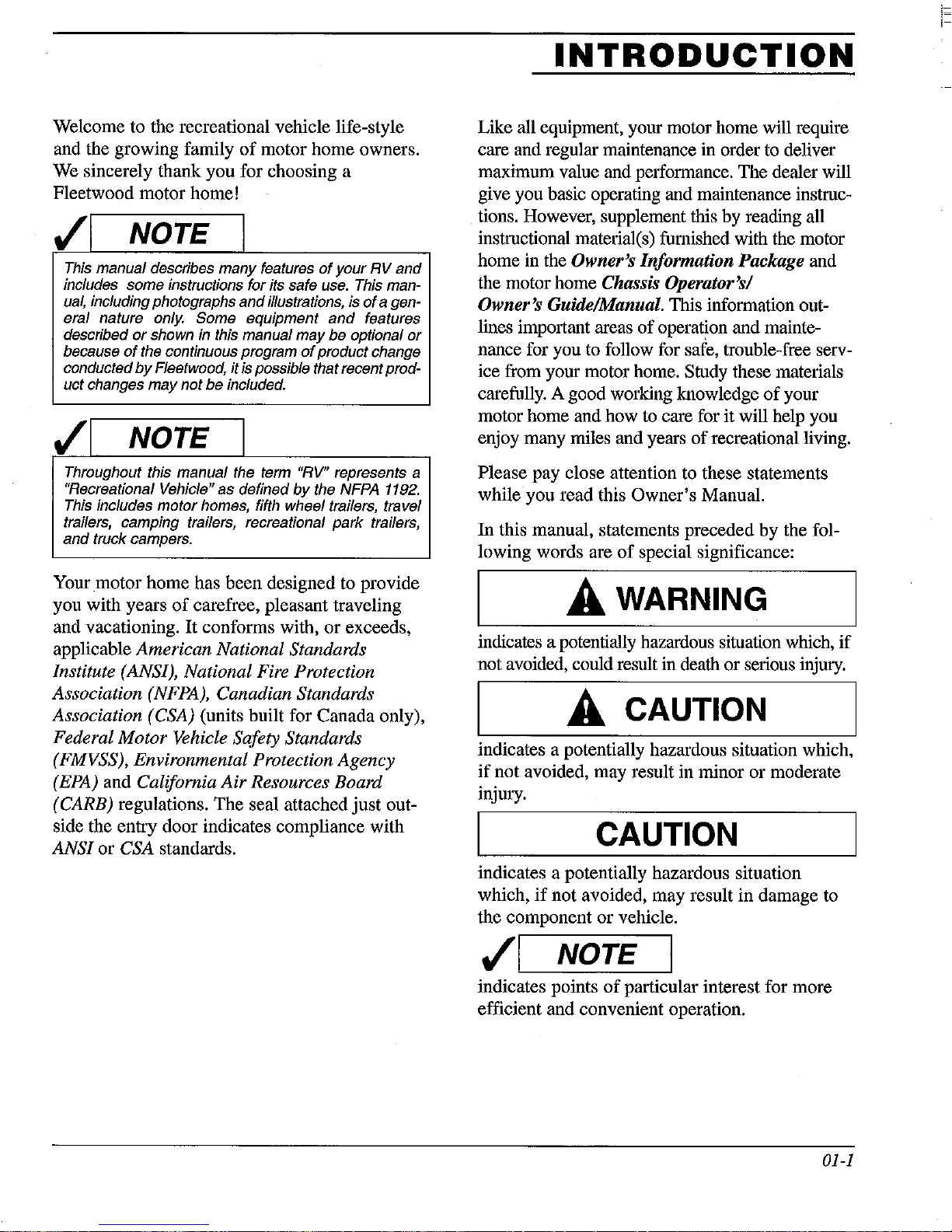
NOTE l
This manual describes many features
of
your
RV
and
includes some instructions for its safe
use.
This man-
ual,
including photographs and illustrations, is
of
a gen-
eral nature only.
Some equipment
and
features
described
or
shown
in
this manual may be optional
or
because
of
the continuous program
of
product change
conducted
by
Fleetwood, it is possible that recent prod-
uct changes
may
not be included.
"I
NOTE 1
Throughout this manual the term "RV" represents a
"Recreational Vehicle" as defined
by
the NFPA
1192.
This includes motor homes, fifth wheel trailers, travel
trailers, camping trailers, recreational park trailers,
and truck campers.
Your
motor
home has been designed to provide
you with years
of
carefree, pleasant traveling
and vacationing.
It
conforms with,
or
exceeds,
applicable
American National Standards
Institute (ANSI), National Fire Protection
Association
(NFPA), Canadian Standards
Association (CSA)
(units built for Canada only),
Federal Motor Vehicle Safety Standards
(FMVSS), Environmental Protection Agency
(EPA) and California
Air
Resources Board
(CARB)
regulations.
The
seal attached
just
out-
side the entry door indicates compliance with
ANSI
or CSA standards.
INTRODUCTION
Like all equipment, your motor home will require
care and regular maintenance in order to deliver
maximum value and performance. The dealer will
give you basic operating and maintenance instructions. However, supplement this by reading all
instructional material(s) furnished with the motor
home in the
Owner's Information Package and
the motor home
Chassis Operator's/
Owner's Guide/Manual.
This information out-
lines important areas
of
operation and maintenance for you to follow for safe, trouble-free service from your motor home. Study these materials
carefully. A good working knowledge
of
your
motor home and how to care for it will help you
enjoy many miles and years
of
recreational living.
Please pay close attention to these statements
while you read this
Owner's Manual.
In this manual, statements preceded by the following words are
of
special significance:
A WARNING
indicates a potentially hazardous situation which,
if
not avoided, could result in death or serious injury.
A CAUTION
indicates a potentially hazardous situation which,
if
not avoided, may result in minor or moderate
injury.
CAUTION
indicates a potentially hazardous situation
which,
if
not avoided, may result
in
damage to
the component or vehicle.
"I NOTE
indicates points
of
particular interest for more
efficient and convenient operation.
01-1
i=
i-
Introduction
If
you have any questions regarding operation,
maintenance, or service, please contact your
dealer immediately so he can assist you. Your
dealer's Service or Sales Department will handle any normal problems which might occur.
Some equipment and features described or
shown in this manual may be optional or not
available on some models.
Because
improvement conducted by Fleetwood, it is possible that recent product changes may not be
included in this manual. Specifications may
change without notice. Product information,
illustrations and photography included in this
Owner's Manual were as accurate as possible at
the time
function and
depiction
or exterior decor or design options as installed
on or in your recreational vehicle.
The instructions included in this manual are
intended as a guide, and in no respect extend the
responsibilities
parent company or affiliates beyond the standard written warranty as presented in this manual.
Fleetwood has designed its recreational vehicles
to provide a variety
Each vehicle features optimal seating, sleeping,
storage and fluid capacities. The user is responsible for selecting the proper combination
loads to ensure that the recreational vehicle's
capacities are not exceeded.
INSPECT AND MAINTAIN
Follow a consistent schedule
maintenance for your motor home. Your contin-
uing safety and comfort depend on it. This man-
ual includes a section outlining maintenance
intervals.
lines, you will minimize the possibility
ure
motor home.
of
the continuous program
of
publication, and are representative
mayor
of
actual equipment, fabrics, interior
If
you follow the maintenance guide-
of
any important system or part
may not be specific in their
of
the manufacturing subsidiary,
of
uses for its customers.
of
product
of
inspection and
of
of
your
of
of
fail-
PLANNING AND PREPARATION
Each year millions
trips using some type
Proper planning
urable experience. A thorough knowledge
your
RV
is important
of
most out
the convenience and safety items
built into your motor home.
it as you are with your personal car or truck.
you have trouble or have questions, please consult your dealer.
of
Americans embark on
of
recreational vehicle.
of
your trip will ensure a pleas-
if
you are going
Be
as
to
get the
familiar with
of
If
OWNER'S INFORMATION
PACKAGE
This package contains valuable documents about
your motor home and its equipment and systems.
This Owner's Manual and the Chassis
Operator's Manual
manual does not cover every possible detail
equipment and options installed on or in your
motor home, there are booklets and instructional
material in the package that will help you safely
operate, maintain and troubleshoot those items.
Be
sure you read all this information
understand the safety
included in the package.
follow all maintenance instructions
warranty coverage.
your motor home, be sure the new owner
receives all the material in this package.
v'1
If your Owner's Information Package
tain these
home
request the desired
NOTE I
items,
"used," please call
Fleetwood American
1420 West Patterson Street
are in the package. Since this
and
operating instructions
Additionally, you must
to
If
you decide
even
if
you purchased your motor
or
or
missing information.
Decatur, Indiana 46733
1-800-435-7345
to
sell or trade
write Fleetwood and
Coach Service
and
insure full
does
not con-
of
';-
01-2
Introduction
!=
i-
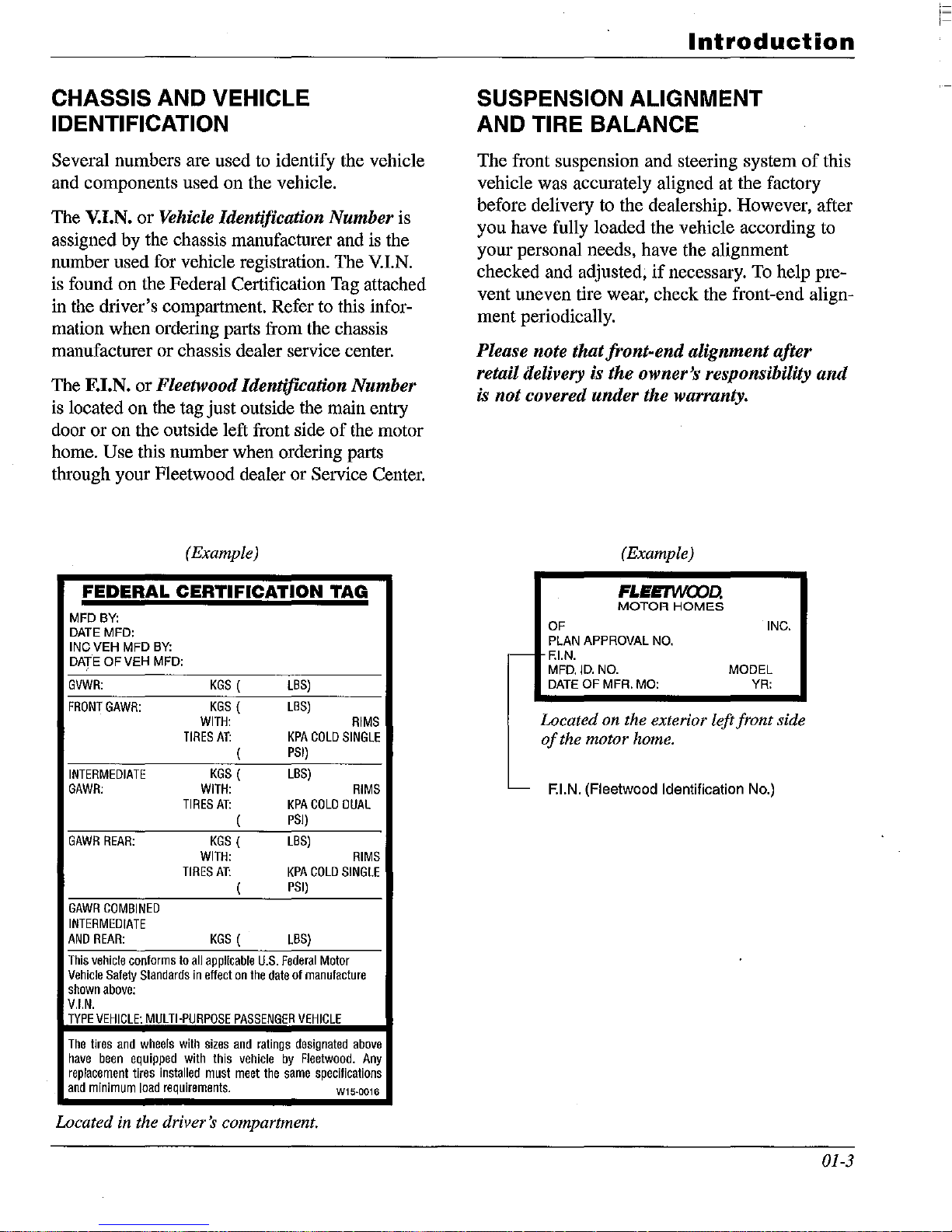
CHASSIS AND VEHICLE
IDENTIFICATION
Several numbers are used to identify the vehicle
and components used on the vehicle.
The V.I.N.
assigned by the chassis manufacturer and is the
number used for vehicle registration. The
is found on the Federal Certification Tag attached
in the driver's compartment. Refer to this infor-
mation when ordering parts from the chassis
manufacturer or chassis dealer service center.
The F.I.N.
is located on the tag just outside the main entry
door
or
home.
through your Fleetwood dealer or
or
Vehicle Identification Number is
V.LN.
or
Fleetwood IdentifICation Number
on the outside left front side
of
the motor
Use this number when ordering parts
Service Center.
SUSPENSION ALIGNMENT
AND
The front suspension and steering system
vehicle was accurately aligned at the factory
before delivery to the dealership. However, after
you have fully loaded the vehicle according to
your personal needs, have the alignment
checked and adjusted,
vent uneven tire wear, check the front-end alignment periodically.
Please note that front-end alignment after
retail delivery is the owner's responsibility
is not covered under the warranty.
TIRE BALANCE
if
necessary.
To
help pre-
of
this
and
(Example)
FEDERAL CERTIFICATION TAG
MFD
BY:
DATE
MFD:
INC
VEH
MFD
DATE
OF
GVWR:
FRONT
GAWR:
INTERMEDIATE
GAWR:
GAWR
REAR:
GAWR
COMBINED
INTERMEDIATE
AND
REAR:
This
vehicle
Vehicle
Safety
shown
above:
V.I.N.
TYPE
VEHICLE:
The
tires
have
been
replacement
and
minimum
BY:
VEH
MFD:
conforms
and
equipped
to
Standards
MULTI·PURPOSE
wheels
with
tires
installed
load
requirements.
WITH:
TIRES
WITH:
TIRES
WITH:
TIRES
ali
applicable
in
effect
sizes
with
must
KGS
(
KGS
(
AT:
(
KGS
(
AT:
(
KGS
(
AT:
(
KGS
(
on
the
PASSENGER
and
this
vehicle
meet
LBS)
LBS)
KPA
PSI)
LBS)
KPA
PSI)
LBS)
KPA
PSI)
LBS)
U.S.
Federal
date
ratings
by
the
same
COLD
COLD
COLD
Motor
of
manufacture
VEHICLE
designated
Fleetwood.
specifications
RIMS
SINGLE
RIMS
OUAL
RIMS
SINGLE
above
Any
W15·0016
(Example)
FLEETWOOD.
MOTOR
OF
PLAN
-
APPROVAL
F.I.N.
MFD.ID.NO.
DATE
OF
MFA.
Located on the exterior left front side
of
the motor home.
- F.I.N. (Fleetwood Identification No.)
MO:
HOMES
NO.
MODEL
YR:
INC.
Located in the driver's compartment.
01-3
Introduction
Excessive or abnormal tire wear may indicate
worn or misaligned suspension or steering components, unbalanced or improperly inflated
tire(s) or some other tire/suspension problem.
Alignment can be affected by worn steering/suspension parts or road hazards such as hitting a
curb, pothole, railroad track, etc. Improper
alignment can cause tires
to
roll at an angle and
wear unevenly.
It
may also cause the vehicle
to
"pull"
to
the right or left.
Out-of-balance tires will not roll smoothly and
will cause annoying vibrations and uneven tread
wear such as cupping or flat spots.
If
you see
uneven tire tread wear or
if
the vehicle ride
comfort decreases, the tires may need to be
balanced.
See the
Chassis Operator's/Owner's Guide/
Manual for more information.
AFTER-MARKET STEERING AID
DEVICES
Fleetwood does not sanction or condone the
installation
of
any steering aid device that is not
approved by our chassis manufacturer's. Any
add-on device
of
this type may void the chassis
manufacturer's warranty on the item or items
affected.
WARNINGS, TERMS AND
CONCEPTS FOR SAFE
OPERATION OF YOUR MOTOR
HOME
Vehicle Crash
01-4
Like any other vehicle you may drive, your
motor home can be involved in a vehicle
crash, including a rollover. The motor home
will be damaged and you and others can be
injured or killed. Drive defensively at all
times.
DO
NOT
drive
if
you are tired, have
been drinking alcoholic beverages, are under
the influence of any controlled substance, or
are taking any medication or drugs that may
impair your sight, hearing, judgment or coordination.
Pull off the road and park in a safe
area until you can drive safely.
Vehicle Handling
Your motor home is longer, wider and
higher than a typical car or truck you may
be accustomed to driving. Keep this in
mind as you become familiar with driving
your motor home. New motor home owners should take special care to learn the
driving and handling characteristics
of
your
vehicle in safe and familiar surroundings.
The distribution
of
the weight
of
your
motor home is designed so it will handle
safely while being driven.
• When loading the motor home, balance
the load front-to-rear
and
side-to-side.
• Load
and
secure heavier items lower in
the storage areas than lighter items.
If
you fail to properly load your belongings and
supplies, you will defeat the load distribution
design
of
the motor home, possibly leading
to
handling problems and a vehicle crash.
Vehicle Response
When you, the driver, accelerate, brake or
steer the motor home, it responds to these
inputs.
If
you are faced with an emergency
while driving, the way you respond to the
emergency and the way the motor home
responds becomes more critical.
If
you
load, alter or maintain your motor home
improperly, it will not respond as it did
when you first received it in an unloaded
condition.
Improper loading, alteration,
maintenance
and
improper driver
responses to emergency conditions can
lead to handling problems and vehicle
crashes.
Vehicle Towing
Your motor home can be equipped with a
hitch designed to allow you to tow vehicles

Introduction
or other loads behind your motor home.
The maximum amount
of
weight your
motor home can pull or stop is determined
by the manufacturer
of
the chassis on
which your motor home is built. Check the
Chassis Operator's/Owner's Guide/
Manual provided by the motor home chas-
sis manufacturer for the limits on the
weight you can tow.
NOTE I
In most cases the GCWR
ished motor home are the same.
to the equipped hitch
reduced. Please refer to the Cargo Carrying Capacity
Tag
posted in your motor home for the rated GCWR.
If
the Chassis Operator's/Owner's Guide/
Manual equipped with your motor home
does not provide specific information on
towing weight limits, it is strongly
recommended that the towed vehicle or
trailer
be
equipped with a properly installed
and operating supplemental brake control
system that operates in combination with
the brakes on your motor home.
o
You
may be able to increase the weight
any towed load by properly installing on the
towed load a supplemental brake control
system that operates with your motor
home's braking system. Even with
tional brakes, you cannot tow more than the
GTW or GCWR for the chassis under your
motor home. Again, check the
Operator's/Owner's Guide/Manual.
o
You
CANNOT
by
limit
o Properly load what you tow
changing the size
vehicle crash.
o Do
not
attempt
too heavy for your chassis.
o
When
look
cerning
driving
for
and
grades
experience when pulling and stopping a
of
the chassis and
In
some cases, due
receiver, the GCWR may be
the
addi-
Chassis
increase the towed weight
of
your hitch.
to
avoid a
to
tow something that is
in
monntainous
areas,
obey highway signs con-
and
curves. Your driving
fin-
of
towed unit on mountain roads will
be
different from what you experience on
level ground.
o State laws in the United States and provin-
ciallaws
in Canada vary concerning towing requirements and limits. Check the
laws in the areas where you anticipate
eling.
Alterations
Many motor home owners like
to
Your Motor Home
to
add a
personal touch to their motor home. But
there is a difference between changing how
your motor home looks versus how it
handles or responds to driver inputs.
expect to make any type
of
alteration
your motor home, consult a professional
who understands the correct way
to
alteration and how the alteration will
change or affect the stability, handling,
vehicle response, and overall performance
and safety of your motor home.
An
improper alteration that affects vehicle
handling or response can cause a vehicle
crash,
and
any improper alteration to the
electrical or Propane systems can cause a
fire
and
can endanger your motor home
and
its occupants. Fleetwood, your chassis
and other manufacturers stand behind the
motor home as delivered -
NOT
as altered
by someone else.
Warning Devices
Your motor home is equipped with warning
devices. Check them before a trip for
proper operation. A disabled warning
device cannot warn you or vehicle
pants
of
a life-threatening danger. Keep
occu-
them working and respond to them quickly.
Examples
o Carbon Monoxide Detector/Alarm
o Propane Detector/Alarm
o Smoke Detector/Alarm
o Seat Belt Warnings
of
These Devices Include:
very
trav-
If
you
to
do the
01-5

Introduction
• Hazard Flashers
• Brake Warning Light
• Engine Warning Light
01-6
EVENT DATA RECORDING DEVICE
(If Equipped)
SPECIAL NOTICE: Vehicle Event Data
Recording Capabilities.
Motor homes equipped with driver/passenger
airbags, Navigational or Vehicle Avoidance
Systems and/or equipped with certain other
electronic devices may be equipped with event
data recording capabilities.
Your motor home is built on a vehicle chassis
supplied by an automotive manufacturer. For
diagnostic and safety related reasons, this
chassis comes equipped with electronic modules
(devices).
<~
1--
LIMITED
ONE-YEAR/THREE
YEAR
WARRANTY
For Motor Homes Manufactured and Warranted
by
subsidiaries
of
Fleetwood
Enterprises, Inc., sold
in
the United States and Canada
COVERAGE PROVIDED
Your new motor home, including the structure,
plumbing, heating and electrical systems, all
appliances and equipment installed by the
manufacturer, is warranted under normal use to
be free from manufacturing defects in material
or
workmanship. Appearance imperfections, or
damage to paint, graphics, exterior materials,
or
upholstery that may have occurred prior to
delivery are normally corrected during the
inspection process at the manufacturing plant or
at the dealership.
The warranty extends to the first retail purchaser
and his transferee(s) and begins on the date
of
original retail delivery or the date the motor
home is first placed into service as a rental,
commercial
or
demonstrator unit (whichever
occurs first). The warranty extends for the following periods:
1.
For all defects (other than structural) the
warranty extends for a period
of
one year
from such date or until the unit has received
15,000 total miles
of
use as determined by
the mileage shown on the odometer
(whichever occurs first).
2.
For structural defects, 3
years/SO,OOO
miles;
structural defects are limited to the following: roof structure, sub-floor structure, and
Vacu-bond®
walls.
Written notice
of
defects must be given to the
selling dealer
or
manufacturer not later than ten
(10) days after the expiration
of
the warranty
period.
WHAT IS NOT COVERED BY
THIS WARRANTY
This
warranty
does
not
cover:
1.
The
automotive chassis system (including
the chassis and drive train), tires and batteries, which are covered by the separate war-
ranties
of
the respective manufacturers
of
these components.
2. Defects caused by or related to:
a.
Abuse, misuse, negligence or accident;
b. Failure to comply with instructions con-
tained in the
Owner's Information
Package;
c. Alteration
or
modification
of
the motor
home;
d.
Environmental conditions (salt, hail,
chemicals in the atmosphere, etc.)
3. Normal deterioration due to wear
or
expo-
sure, such as fading
of
fiberglass, fabrics
or
drapes, carpet wear, etc.
4. Normal maintenance and service items,
such as light bulbs, fuses, wiper blades,
lubricants, etc.
5. Motor homes on which the odometer reading has been altered.
6.
Transportation to and from dealer or
Fleetwood Service Center location, loss
of
time, inconvenience, commercial loss, loss
of
use, towing charges, bus fares, vehicle
rental, incidental charges such as telephone
calls or hotel bills,
or
other incidental
or
consequential damages.
7. Fleetwood will
NOT be responsible for any
losses, damages, or claims, including, but
not limited to, property damage, personal
injury, loss
of
income, legal fees or
expenses, emotional distress, death, loss
of
use, loss
of
value, all other economic
loss, adverse health effects,
or
any other
effects caused
or
alleged to
be
caused by
MICROBIAL MATTER, including, but not
limited to, mold, mildew, fungus or dry rot.
THE
IMPLIED WARRANTIES ARE
LIMITED IN
DURATION TO THE
EXPRESS TERMS OF THIS
113
YEAR
WARRANTY.
02-1
,~
I~
Warranty
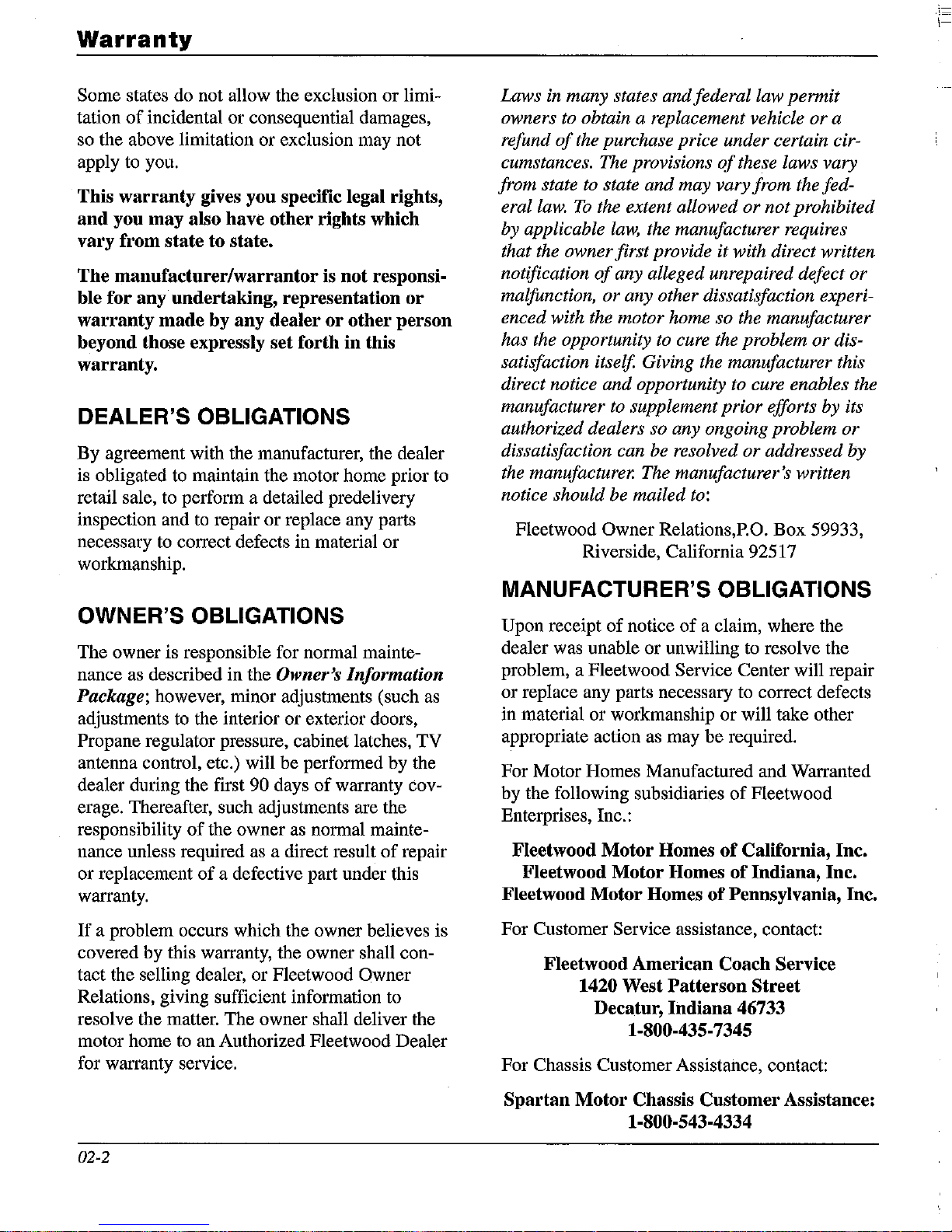
Some states do not allow the exclusion or limitation
of
incidental or consequential damages,
so the above limitation or exclusion may not
apply to you.
This warranty gives you specific legal rights,
and you may also have other rights which
vary from state to state.
The manufacturer/warrantor
is
not responsi-
ble for any undertaking, representation
or
warranty made by any dealer
or
other person
beyond those expressly set forth in this
warranty.
DEALER'S OBLIGATIONS
By
agreement with the manufacturer, the dealer
is obligated
to
maintain the motor home prior
to
retail sale, to perform a detailed predelivery
inspection and
to
repair or replace any parts
necessary
to
correct defects in material or
workmanship.
OWNER'S OBLIGATIONS
The owner is responsible for normal maintenance
as
described in the Owner's Information
Package;
however, minor adjustments (such
as
adjustments
to
the interior or exterior doors,
Propane regulator pressure, cabinet latches, TV
antenna control, etc.) will be performed by the
dealer during the first
90 days
of
warranty coverage. Thereafter, such adjustments are the
responsibility
of
the owner as normal mainte-
nance unless required as a direct result
of
repair
or replacement
of
a defective part under this
warranty.
If
a problem occurs which the owner believes is
covered by this warranty, the owner shall contact the selling dealer, or Fleetwood
Owner
Relations, giving sufficient information to
resolve the matter. The owner shall deliver the
motor home
to
an Authorized Fleetwood Dealer
for warranty service.
02-2
Laws in many states and federal law permit
owners
to
obtain a replacement vehicle or a
refund
of
the purchase price under certain cir-
cumstances. The provisions
of
these laws vary
from state
to
state and may vary from the fed-
erallaw.
To
the extent allowed or not prohibited
by applicable
law,
the manufacturer requires
that the owner first provide it with direct written
notification
of
any alleged unrepaired defect or
malfunction, or any other dissatisfaction experienced with the motor home so the manufacturer
has the opportunity
to
cure the problem or dissatisfaction itself. Giving the manufacturer this
direct notice and opportunity to cure enables the
manufacturer
to
supplement prior efforts by its
authorized dealers so any ongoing problem or
dissatisfaction can
be
resolved or addressed by
the manufacturer. The manufacturer's written
notice should be mailed
to:
Fleetwood Owner Relations,P.O. Box 59933,
Riverside, California 92517
MANUFACTURER'S OBLIGATIONS
Upon receipt
of
notice
of
a claim, where the
dealer was unable or unwilling
to
resolve the
problem, a Fleetwood Service Center will repair
or replace any parts necessary to correct defects
in material or workmanship or will take other
appropriate action as may
be
required.
For Motor Homes Manufactured and Warranted
by the following subsidiaries
of
Fleetwood
Enterprises, Inc.:
Fleetwood Motor Homes
of
California, Inc.
Fleetwood Motor Homes of Indiana, Inc.
Fleetwood Motor Homes
of
Pennsylvania, Inc.
For Customer Service assistance, contact:
Fleetwood American Coach Service
1420 West Patterson Street
Decatur, Indiana 46733
1-800-435-7345
For Chassis Customer Assistance, contact:
Spartan Motor Chassis Customer Assistance:
1-800-543-4334
\-
Warranty
1=
,-
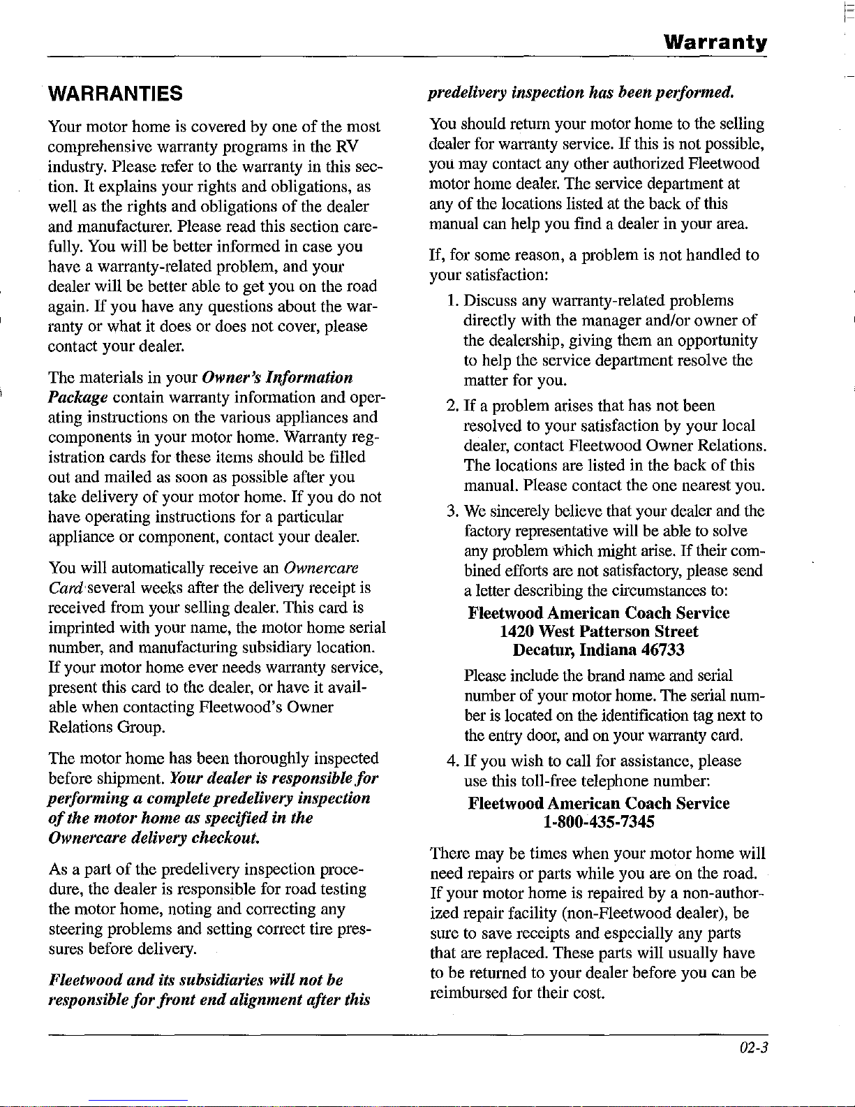
WARRANTIES
Your motor home is covered by
comprehensive warranty programs in the RV
industry.
tion.
well as the rights and obligations
and manufacturer.
fully.
have a warranty-related problem, and your
dealer will
again.
ranty or
contact your dealer.
The materials
Please refer to the warranty in this sec-
It
explains your rights and obligations, as
Please read this section care-
You will
If
what
be
better informed in case you
be
better able to
you have any questions about the war-
it does
in
or
does not cover, please
your Owner's Information
Package contain warranty information and oper-
ating instructions on the various appliances and
components in your motor home. Warranty reg-
istration cards for these items should
out and mailed as soon as possible after you
take delivery
have operating instructions for a particular
appliance
You will automatically receive an Ownercare
of
your motor home.
or
component, contact your dealer.
Card several weeks after the delivery receipt is
received from your selling dealer. This card is
imprinted with your name, the motor home serial
number, and manufacturing subsidiary location.
If
your motor home ever needs warranty service,
present this card to the dealer, or have it avail-
able when contacting Fleetwood's
Relations Group.
The motor
before shipment.
home
has been thoroughly inspected
Your dealer is responsible
performing a complete predelivery inspection
of
the motor home as specified in the
Ownercare delivery checkout.
As a part
dure, the dealer is responsible for road testing
the motor home, noting and correcting any
steering problems and setting correct tire pressures before delivery.
Fleetwood
responsible
of
the predelivery inspection proce-
and
its subsidiaries will
for
front
end
alignment after this
one
of
of
the dealer
get
you on the road
be
If
you do not
Owner
not
the most
filled
for
be
predelivery inspection has been performed.
You should return your motor home to the selling
If
dealer for warranty service.
you may contact any other authorized Fleetwood
motor home dealer. The service department at
any
of
the locations listed
manual can help you find a dealer
If,
for some reason, a problem is not handled
your satisfaction:
1.
Discuss any warranty-related problems
directly with the manager and/or owner
the dealership, giving them an opportunity
to help the service department resolve the
matter for you.
If
a problem arises that has not been
2.
resolved to your satisfaction
dealer, contact Fleetwood
The locations are listed in the back
manual.
3.
We sincerely believe that your dealer and the
factory representative will
any problem
bined efforts are not satisfactory, please send
a letter describing the circumstances to:
Fleetwood
Please include the brand name and serial
number of your motor home. The serial number is located on the identification tag next to
the entry door, and on your warranty card.
4.
If
you wish to call for assistance, please
use this toll-free telephone number:
Fleetwood
There may
need repairs
If
your motor home is repaired
ized repair facility (non-Fleetwood dealer),
sure to save receipts and especially any parts
that are replaced. These parts will usually have
to
be
returned to your dealer before you can
reimbursed for their cost.
Please contact the one nearest you.
Which
American
1420
West
Patterson
Decatur,
be
times when your motor home will
or
Indiana
American
1-800-435-7345
parts while you are
this is not possible,
at
the back
in
your area.
by
Owner
be
able to solve
might arise.
Coach
Coach
If
Service
Street
46733
Service
on
by
a non-author-
of
this
to
of
your local
Relations.
of
this
their com-
the road.
be
be
02-3
Warranty
WARRANTY SERVICE
If
you need service or warranty information,
please see the booklets and other documents
included in your
Owner's Information
Package.
When contacting any
of
the
equipment manufacturers, always have the
model and serial numbers available. Appliance
identification numbers will be found on tags or
plates attached
to
the appliance.
If
you ever need warranty work done, be sure to
have the right papers
with you.
If
required work
is not covered under the warranty, your dealer's
service department can help you with getting the
correct service. Always keep a maintenance log
of
your RV's service history.
Always make a written list
of
the RV's problems
or the specific work you want done.
If
you've
had work done that is not on your maintenance
log, let the service advisor know. Don't keep
secrets.
And finally, be reasonable with requests.
If
you
have a long list
of
service items that need atten-
tion and you need your
RV
very soon, discuss
the situation with the service advisor, listing the
items in order
of
priority. This will help the
service department manage their time and will
help get you going as quickly as possible.
If
you have a warranty or service concern about
the chassis portion
of
your vehicle please be
aware that you may go directly
to
an authorized
chassis dealer for service. This may save you
time and effort as the chassis warranty is
administered by the chassis manufacturer.
Consult your area phone directory for an author-
ized dealer and make arrangements with their
service department.
If
you are unsure
if
the con-
cern is chassis related, feel free to contact your
Fleetwood dealer to assist you.
02-4
REPORTING SAFETY DEFECTS
If
you believe that your vehicle has a defect
which could cause a crash, injury, or death, you
should immediately inform the National
Highway Traffic Safety Administration (NHTSA)
in addition to notifying the Fleetwood American
Coach Service at 1-800-435-7345.
If
NHTSA receives similar complaints, it may
open an investigation, and
if
it finds that a
safety defect exists in a group
of
vehicles, it
may order a recall and remedy campaign.
To
contact NHTSA, you may either call the Auto
Safety Hotline toll-free at 1-888-327-4236 or
write to:
NHTSA
U.S.
Department
of
Transportation
400 Seventh St.
SW
Washington,
DC
20590
You
can also obtain other information about
motor vehicle safety from the Hotline.
j--

1-
1--
State laws
laws in
in
the United States and provincial
Canada
vary concerning operator
licensing requirements and vehicle dimensional restrictions. Check the laws in the area
where you anticipate traveling.
The particle board, hardwood plywood, or paneling used in your motor home are made with
urea-formaldehyde resin. The companies that
supply us with these materials have asked that
we tell you about urea-formaldehyde with the
statements
Ventilation
of
your motor home comfortable. Please read
on
this page.
is
important for making the interior
the section about ventilation and prolonged
occupancy
Home
We
provide you consumer information as detailed
in
the Living With Your Motor
chapter in this Owner's Manual.
by the National Fire Protection Association
(NFPA) and the American National Standards
Institute
(ANSI). The information and warnings
found on these pages may also be found in other
chapters
of
this Owner's Manual. Please see the
Propane System and Appliances chapters for
other safety and operating information.
A WARNING
IMPORTANT
A WARNING
Irritant: This product contains a urea·formalde·
hyde resin and may release formaldehyde
vapors in low concentrations. Formaldehyde
can be irritating to the eyes and upper respira'
tory system
such as those with
ments. Use with adequate ventilation. If symp·
toms develop, consult your physician.
of
especially susceptible persons
A WARNING
Do
not
bring
gasoline
vehicle because a fire
result.
A warning label has been located near the
Propane container. This
FILL CONTAINER(S)
CENT OF CAPACITY.
FAILURE
FIRE
Overfilling the Propane container can result in
uncontrolled Propane flow
fire
will contain
volume as liquid Propane.
or
OR
or
explosion. A properly filled container
or
store Propane containers,
other flammable liquids inside the
TO
COMPLY COULD RESULT
PERSONAL
approximately ao· percent
NOTICES
allergies
TO
INJURY.
or
respiratory ail·
or
explosion
label reads:
MORE
THAN
which
may
DO
NOT
aO·PER·
IN
can cause
of
its
This product is manufactured with urea·formaldehyde resin. Formaldehyde vapor may in some
people cause headaches,
irritation, and aggravation of
tory problems, such as asthma. Proper ventilation
should reduce the risk
eye,
nose and throat
allergies and respira·
of
such problems.
A WARNING
This product
formaldehyde
quantities
els
in
the
and respiratory irritation, and may aggravate
respiratory conditions
will reduce indoor
is
manufactured with a urea·
resin and
of
formaldehyde. Formaldehyde lev-
indoor air can cause temporary eye
formaldehyde levels.
will
release small
or
allergies. Ventilation
following warning label has been placed
The
In
the vehiCle near the range:
WARNING
IF
YOU
SMELL PROPANE:
1.
Extinguish any open flames, pilot lights,
and all smoking materials.
2.
Do
not
touch electrical switches.
3.
Shut
off
the Propane supply at the
tainer valve(s)
connection.
4.
Open doors and other ventilation openings.
5.
Leave the area until the
6.
Have the Propane system checked and
leakage
again.
FAILURE
FIRE
OR
source
TO
COMPLY COULD RESULT
PERSONAL
or
Propane
odor
clears.
corrected before
INJURY.
supply
con·
using
IN
03·1
Important
i-
Notices
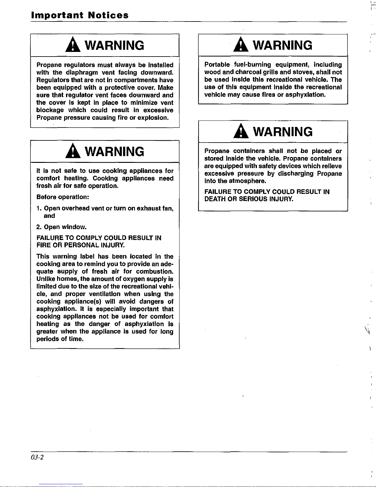
A WARNING
Propane regulators must always be installed
with the diaphragm vent facing downward.
Regulators that are
been equipped with a protective cover. Make
sure that regulator vent faces downward and
the cover
blockage which could result in excessive
Propane pressure causing fire or explosion.
is
kept in place to minimize vent
not
in compartments have
A WARNING
It is
not
safe to use cooking appliances
comfort heating. Cooking appliances need
fresh air
Before operation:
1.
Open overhead vent
and
for
safe operation.
or
turn on exhaust fan,
for
A WARNING
Portable fuel-burning equipment, including
wood and charcoal
be used inside
use
of
this
equipment inside the recreational
vehicle may cause fires
grills
and stoves, shall
this
recreational vehicle. The
or
asphyxiation.
not
A WARNING
Propane containers shall
stored inside the vehicle. Propane containers
are equipped with safety devices which relieve
excessive pressure
into the atmosphere.
FAILURE
DEATH
TO
COMPLY COULD RESULT
OR
SERIOUS
by
not
be placed
discharging Propane
INJURY.
or
IN
2.
Open window.
FAILURE
FIRE
This warning label has been located in the
cooking area
quate supply
Unlike homes, the amount
limited due to the size
cle, and proper ventilation when using the
cooking appliance(s) will avoid dangers
asphyxiation. It
cooking appliances
heating as the danger
greater when the appliance
periods
TO
OR
PERSONAL
of
time.
COMPLY COULD RESULT
INJURY.
to
remind you to provide an ade-
of
fresh air for combustion.
of
oxygen supply is
of
the recreational vehi-
is
especially important that
not
be used
of
for
comfort
asphyxiation
is
used
for
IN
of
is
long
\~
03-2
AMERICAN
COACH
INFORMATION
Eagle
and
Tradition
Information
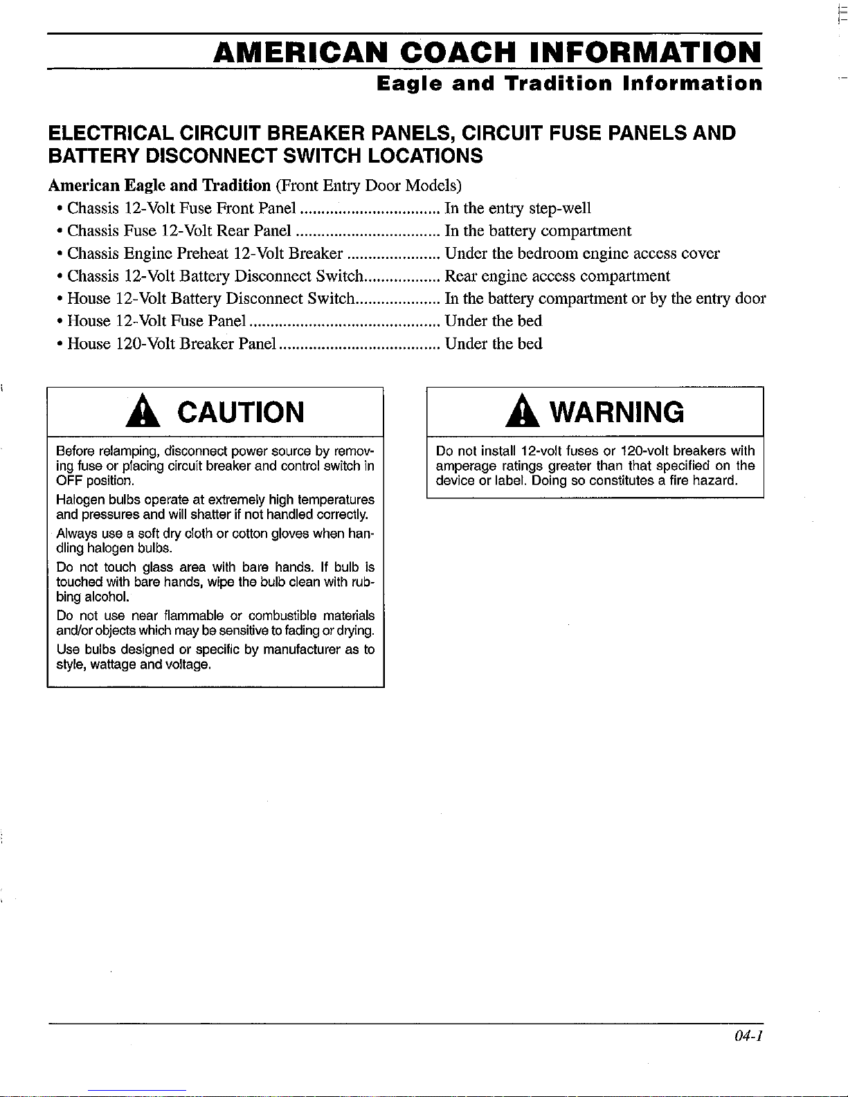
ELECTRICAL CIRCUIT BREAKER PANELS, CIRCUIT FUSE PANELS AND
BATTERY DISCONNECT SWITCH LOCATIONS
American Eagle and Tradition (Front Entry Door Models)
• Chassis 12-Volt Fuse Front Panel ................................. In the entry step-well
• Chassis Fuse 12-Volt Rear Panel .................................. In the battery compartment
• Chassis Engine Preheat 12-Volt Breaker ...................... Under the bedroom engine access cover
• Chassis 12-Volt Battery Disconnect Switch .................. Rear engine access compartment
• House 12-Volt Battery Disconnect Switch .................... In the battery compartment or by the entry door
• House 12-Volt Fuse Panel ............................................. Under the bed
• House 120-Volt Breaker Panel ...................................... Under the bed
A CAUTION
Before relamping, disconnect power source by removing fuse or placing circuit breaker and control switch in
OFF position.
Halogen bulbs operate at extremely high temperatures
and pressures and
will shatter if not handled correctly.
Always use a soft dry cloth or cotton gloves when handling halogen bulbs.
Do not touch glass area with bare hands. If bulb is
touched with bare hands, wipe the
bulb clean with rub-
bing alcohol.
Do
not use near flammable or combustible materials
and/or objects which may be sensitive
to
fading or drying.
Use
bulbs designed or specific by manufacturer as
to
style, wattage and Voltage.
A WARNING
Do not install 12-volt fuses or 120-volt breakers with
amperage ratings greater than that specified on the
device or
label. Doing so constitutes a fire hazard.
04-1
Eagle
and
Tradition
Information
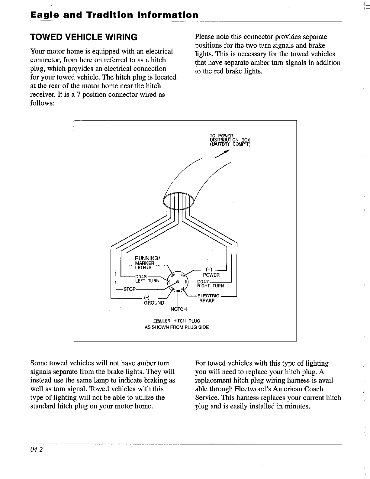
TOWED VEHICLE WIRING
Your motor home is equipped with an electrical
connector, from here on referred
to
as
a hitch
plug, which prqvides an electrical connection
for your towed vehicle. The hitch plug is located
at the rear
of
the motor home near the hitch
receiver. It is a 7 position connector wired as
follows:
RUNNINGI
MARKER
LIGHTS
D048
LEFT
TURN
STOP---.../'~
NOTCH
Please note this connector provides separate
positions for the two turn signals and brake
lights. This is necessary for the towed vehicles
that have separate amber turn signals in addition
to
the red brake lights.
TO
POWER
QISTRIBUTION
BOX
(BATTERY
COMP'T)
(+)
POWER
TRAILER
HITCH
PLUG
AS
SHOWN
FROM
PLUG
SIDE
Some towed vehicles will not have amber turn
signals separate from the brake lights. They will
instead use the same lamp to indicate braking as
well as turn signal. Towed vehicles with this
type
of
lighting will not be able to utilize the
standard hitch plug on your motor home.
04-2
For towed vehicles with this type
of
lighting
you will need to replace your hitch plug. A
replacement hitch plug wiring harness is available through Fleetwood's American Coach
Service. This harness replaces your current hitch
plug and is easily installed in minutes.
,-
'-
\-
10
12
t
Il
54
- VIP
MODULAR
Head
Lamp
Assh
Cruise
0nI0H
Cruise
cancel
LAYOUT
Marker Lamp
R
....
Wi
....
Off
WiperHVLo
Wiper
Variable
Wiper
Wash
C
1ft
JJ
I»
<
U2
m
-
JJ
CD
en
I»
0
~
0
a.
z
...
-I
..
JJ
I»
0
a.
_.
r
..
(JJ
_.
0
~
-
~
-
0
..
:I
I»
..
_.
0
~
-I-III
Eagle
and
Tradition
Information
56
61
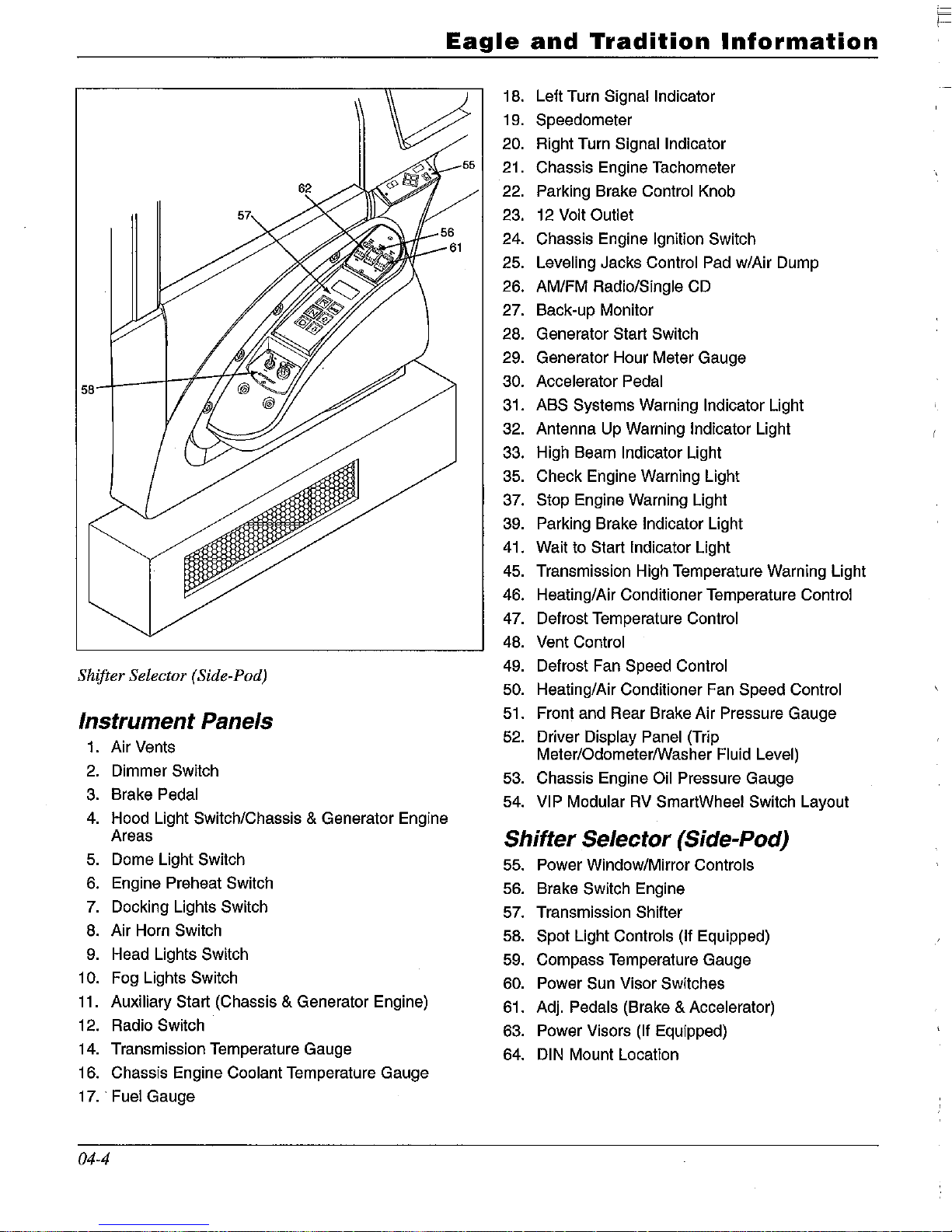
Shifter Selector (Side-Pod)
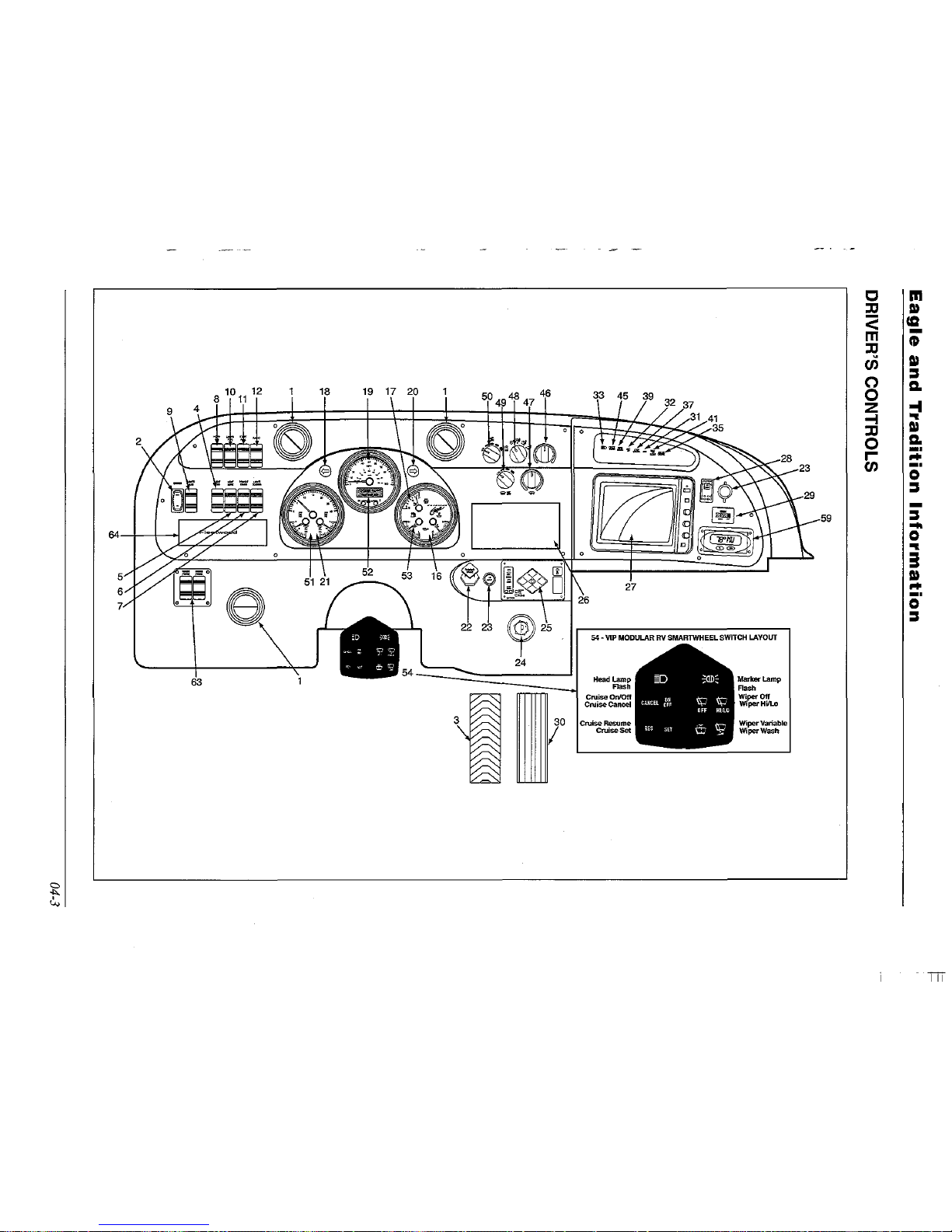
Instrument Panels
1. Air Vents
2.
Dimmer Switch
3.
Brake Pedal
4.
Hood Light Switch/Chassis & Generator Engine
Areas
5.
Dome Light Switch
6.
Engine Preheat Switch
7. Docking Lights Switch
8.
Air Horn Switch
9.
Head Lights Switch
10. Fog Lights Switch
11.
Auxiliary Start (Chassis & Generator Engine)
12. Radio Switch
14. Transmission Temperature Gauge
16. Chassis Engine
Coolant Temperature Gauge
17
..
Fuel Gauge
04-4
55
18.
19.
20.
21.
22.
23.
24.
25.
26.
27.
28.
29.
30.
31.
32.
33.
35.
37.
39.
41.
45.
46.
47.
48.
49.
50.
51.
52.
Left Turn
Signal Indicator
Speedometer
Right Turn
Signal Indicator
Chassis Engine Tachometer
Parking Brake
Control Knob
12
Volt Outlet
Chassis Engine Ignition Switch
Leveling Jacks Control Pad w/Air Dump
AM/FM
Radio/Single CD
Back-up Monitor
Generator Start Switch
Generator Hour Meter Gauge
Accelerator Pedal
ABS
Systems Warning Indicator Light
Antenna Up Warning
Indicator Light
High Beam
Indicator Light
Check Engine Warning Light
Stop Engine Warning Light
Parking Brake
Indicator Light
Wait to Start
Indicator Light
Transmission High Temperature Warning Light
Heating/Air Conditioner Temperature
Control
Defrost Temperature Control
Vent Control
Defrost Fan Speed Control
Heating/Air Conditioner Fan Speed Control
Front and Rear Brake Air Pressure Gauge
Driver
Display Panel (Trip
Meter/OdometerlWasher
Fluid Level)
53. Chassis Engine Oil Pressure Gauge
54.
VIP Modular
RV
SmartWheel Switch Layout
Shifter Selector (Side-Pod)
55. Power Window/Mirror Controls
56. Brake Switch Engine
57. Transmission Shifter
58.
Spot Light Controls (If Equipped)
59. Compass Temperature Gauge
60. Power Sun Visor Switches
61.
Adj.
Pedals (Brake & Accelerator)
63. Power Visors (If Equipped)
64.
DIN Mount Location
~
1---
Heritage
Information
ELECTRICAL CIRCUIT BREAKER PANELS, CIRCUIT FUSE PANELS AND
BATTERY DISCONNECT SWITCH LOCATIONS
American Heritage
• Chassis 12-Volt Fuse Front Panel .................................
In
the entry step-well
• Chassis Fuse 12-Volt Fuse Rear
PaneL
........................
In
the battery compartment
• Chassis 12-Volt Battery Disconnect Switch .................. Rear engine access compartment
• House 12-Volt Battery Disconnect Switch .................... By the entry door
• House 12-Volt Fuse Panel ............................................. Under the bed top
• House 120-Volt Breaker Panel ...................................... Under the bed top
A CAUTION A WARNING
Before relamping, disconnect power source by removing fuse or placing circuit breaker and control switch
in
OFF position.
Do not
install 12-volt fuses
or
120-volt breakers with
amperage ratings greater than that specified on the
device or
label. Doing so constitutes a fire hazard.
Halogen bulbs operate at extremely high temperatures
and pressures and will shatter if not
handled correctly.
Always
use a soft dry cloth or cotton gloves when han-
dling halogen bulbs.
Do not touch glass area with bare hands. If bulb is
touched with bare hands, wipe the
bulb clean with rub·
bing alcohol.
Do
not use near flammable or combustible materials
and/or objects which may be sensitive
to
fading or drying .
. Use bulbs designed or specific by manufacturer as
to
style, wattage and voltage.
04-5
1=

TOWED VEHICLE WIRING
Your motor home is equipped with an electrical
connector, from here on referred
to
as a hitch
plug, which provides an electrical
conne<;tion
for your towed vehicle. The hitch plug is located
at the rear
of
the motor home near the hitch
receiver.
It
is a 7 position connector wired as
follows:
RUNNING!
MARKER
LIGHTS
0048
LEFT
::CTU=RN~
STOP---.../'*
NOTCH
Heritage
Information
Please note this connector provides separate
positions for the two turn signals and brake
lights. This is necessary for the towed vehicles
that have separate amber turn signals in addition
to
the red brake lights.
TO
POWER
QISTRIBUTION
BOX
(BATIERY
COMP'T)
(+)
POWER
0047
:-==---'
RIGHT
TURN
ELECTRIC
BRAKE
TRAILER
HITCH
pLUG
AS
SHOWN
FROM
PLUG
SIDE
Some towed vehicles will not have amber turn
signals separate from the brake lights. They will
instead use the same lamp
to
indicate braking as
well as turn signal. Towed vehicles with this type
of
lighting will not be able to utilize the standard
hitch plug on
your motor home.
04-6
For towed vehicles with this type
of
lighting you
will need to replace your hitch plug. A replacement hitch plug wiring harness is available
through Fleetwood's American Coach Service.
This harness replaces your current hitch plug and
is easily installed in minutes.
~
)--
Heritage
Information
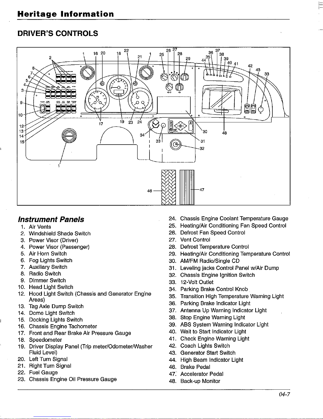
DRIVER'S CONTROLS
3
9
10
17
19
23 24
12
n
13
14
34
15
46-tV',
Instrument Panels
24.
1.
Air Vents
25.
2.
Windshield Shade Switch
26.
3. Power Visor (Driver)
27.
4.
Power Visor (Passenger) 28.
5.
Air Horn Switch
29.
6.
Fog Lights Switch
30.
7.
Auxiliary Switch
31.
8.
Radio Switch
32.
9.
Dimmer Switch
33.
10. Head Light Switch
34.
12.
Hood Light Switch (Chassis and Generator Engine
35.
Areas)
36.
13.
Tag
Axle Dump Switch
14. Dome Light Switch
37.
15. Docking Lights Switch
38.
16. Chassis Engine Tachometer
39.
17. Front and Rear Brake Air Pressure Gauge
40.
18. Speedometer
41.
19. Driver
Display Panel (Trip meter/Odometer/Washer
42.
Fluid Level)
43.
20. Left Turn Signal
44.
21. Right Turn
Signal
46.
22.
Fuel Gauge
47.'
23. Chassis Engine Oil Pressure Gauge
48.
36
37
35
38
44
39
40
41
R
30
48
31
32
47
42
Chassis Engine Coolant Temperature Gauge
Heating/Air Conditioning Fan Speed
Control
Defrost Fan Speed Control
Vent Control
Defrost Temperature Control
Heating/Air Conditioning Temperature Control
AM/FM Radio/Single CD
Leveling jacks Control Panel w/Air Dump
Chassis Engine
Ignition Switch
12-Volt Outlet
Parking Brake Control Knob
Transition High Temperature Warning Light
Parking Brake
Indicator Light
Antenna Up Warning
Indicator Light
Stop Engine Warning Light
ABS System Warning
Indicator Light
Wait to Start
Indicator Light
Check Engine Warning Light
Coach Lights Switch
Generator Start Switch
High Beam
Indicator Light
Brake
Pedal
Accelerator Pedal
Back-up Monitor
04-7
53
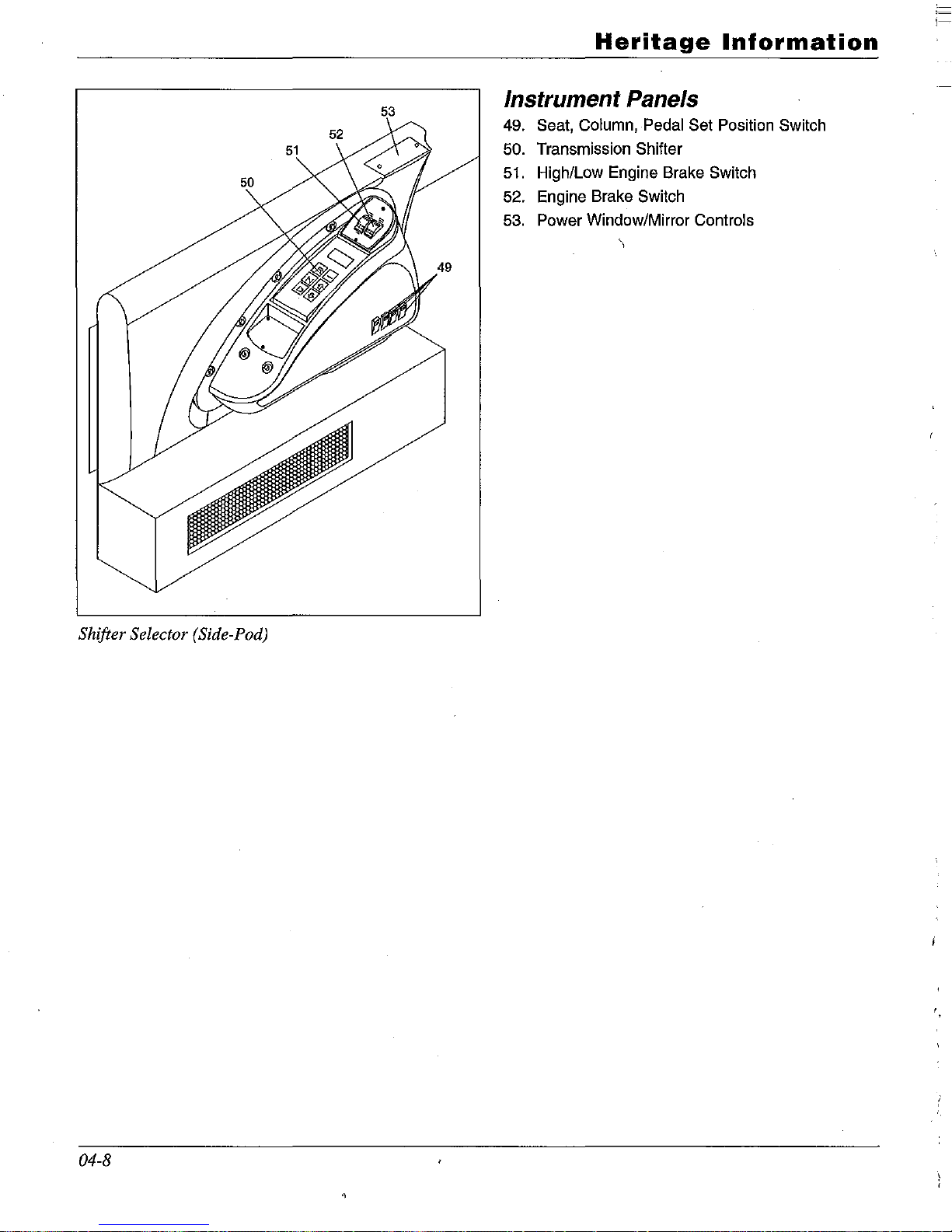
Shifter Selector (Side-Pod)
04-8
Heritage
Information
Instrument Panels
49. Seat, Column, Pedal Set Position Switch
50. Transmission Shifter
51.
High/Low Engine Brake Switch
52. Engine Brake Switch
53. Power Window/Mirror Controls
\
i-
'.
Heritage
Information
LIVING WITH YOUR MOTOR HOME
MONITOR
PANEL
Your motor home is equipped with a computer.
The computer will operate the Monitor
Panel
System. The motor home will have two color
display screens. One is located in the dash and
the other monitor is located in the control panel
display center.
Your
Network Computer Information Package
contains detailed operating and maintenance
instructions concerning the system.
PLUMBING SYSTEMS AND
HOLDING TANKS
DRAINING
THE HOLDING TANKS
The holding tanks terminate in a valve arrangement that permits draining
of
each tank separately. The valves are called knife valves. A
blade closes the opening in the sewer drain
pipes. The blade is connected to a 12-Volt
electric motor. A button will activate the knife valve
for discharging the wastewater from the
RV.
During self-containment use, the sewer line is
securely capped
to
prevent leakage
of
waste
material onto the ground or pavement.
Do not
activate the knife valve when the protective cap
is installed on the pipe.
Always drain the tank
into an acceptable sewer inlet or dump station.
Drain the holding tanks only when they are at
least 3/4 full.
If
necessary, fill the tanks with
water to 3/4 full. This provides sufficient water
to allow complete flushing
of
waste material
into the sewer line.
Whenever possible, drain the holding tanks
before traveling. Wastewater and sewage in the
holding tanks reduces the carry capacity
of
the
motor home. See the Motor Home Loading
chapter.
During extended or semi-permanent hook-ups to
sewage systems, waste materials will build up in
the tank and cause serious plugging.
If
the tank
valves are continuously open. In these cases,
keep the valve closed until the tanks are 3/4 full,
and then drain into the sewage system.
The holding tank drain valve outlet is to be used
with a removable termination fitting that locks
onto the outlet with a clockwise twist. Clamp
the sewer hose drain to this fitting. A protective
cap should remain in place when you are not
draining the tanks.
To
drain
the holding tanks:
1.
Attach the sewer hose to the holding tank
outlet. Insert the end
of
the hose into the
sewer or dump station inlet, pushing it
firmly far enough into the opening
to
be
secure. In some cases, adapters may be
necessary or required between the line and
the inlet. Arrange the sewer hose so it
slopes evenly.
2.
Drain the black water holding tank first.
Push the dump switch up towards the word
"open" and watch for discharge down the
sewer hose. The valve will open in 1-2
seconds and an LED light will come on. Do
not hold the switch for more than 2 seconds.
3.
Allow enough time for the tank to drain
completely. When the tanks is empty push
the rocker switch to the "close" position.
Again the valve will open in 1-2 seconds.
The LED light will go out when the valve
is completely closed. Run enough water
(up to five gallons or so) into the tank to
cover the bottom. This will aid the break
up.
of
solid wastes, and reduce "pyramid-
ing"
of
waste material.
4.
To
drain the gray water tank, repeat the
steps above using the other knife valve.
This tank is drained last to aid in flushing
the outlets and hose. The gray water knife
valve may be left open in a
semi-perma-
nent hookup.
04-9
1-
,--
5.
See the tank flush system instructions in
the next section
if
your recreational vehicle
is so equipped.
6.
Remove out the sewer hose and cap the
outlet.
7. Rinse out the sewer hose with fresh water
and remove the sewer hose from the dump
station.
8.
Replace sewer or dump station covers.
A CAUTION
The sewer drain valve must be open when using the
black tank flush inlet.
04-10
Heritage
Information
ELECTRICAL SYSTEMS
Battery Charging
Your motor home is equipped with AGM sealed
batteries. These batteries do not contain electrolyte (fluid). They are designed to be maintenance free with proper use
Please refer
to
the Owner's Manual for further
information regarding the Battery Charging
System.
Automatic Generator Start Control
System
Your motor home is equipped with a computer.
The computer will operate the Automatic
Generator
Start Control. The motor home will
have two color display screens.
One is located
in the dash and the other monitor is located in
the control panel display center.
Your
Network Computer Information Package
contains detailed operating and maintenance
instructions concerning the system.
,-
Heritage
Information
HERITAGE NETWORK COMPUTER
SYSTEM
OVERVIEW
The Coach Network Computer System represents a technology leap in the Recreational
Vehicle industry. The Coach Network Computer
System combines an array
of
formerly individual features into one system. The Coach
Network Computer System will present these
combined features to the user in a clear,
comprehensive, consistent manner such as never
been available to the Recreational Vehicle
owner.
The Coach Network Computer System incorpo-
rates user trip information along with Global
Position Mobile Navigation. Basic engine and
transmission information is provided for monitoring chassis performance. Tank levels, remote
cameras, outside temperature, automatic generator functions, along with alerts are all provided
using touch screen technology. In addition the
system will issue service reminders
as
well as
provide the owner with a departure checklist
just
as
a reminder for items that need
to
be
stowed prior
to
driving away.
The Coach Network Computer System consists
of
three major components: the network computer, touch screen displays, and a wireless keyboard. The network computer collects and distributes the information required by the system
to perform its function.
1\vo touch screen dis- .
plays provide the user the ability
to
select and
view important information from two different
locations in the coach. In addition the touch
screen displays give the user the ability to
change various items such as operational parameters, warning set points, and the ability to activate or deactivate certain functions. From any
location inside the coach the wireless keyboard
will provide an alternate method
to
selecting
and activating function as
if
touching the touch
screen. The wireless keyboard will also allow
the user to input mapping information into the
Global Position Mobile Navigation system.
This
Owner's Manual will deal mostly with the
operation and interaction with the touch screen
displays. These touch screen displays are the
owner's interface to the powerful Coach
Network Computer system.
Table 1 list the features
of
the Coach Network
Computer System. The following paragraphs
will describe each
of
these features.
GETTING STARTED
Before we start the description
of
each function
we will take a moment to identify stylistic
issues along with a few conventions used by the
Coach Network Computer System.
The display screens are touch screens. Touch
screen means that the user can touch defined
areas on the display screen surface and select or
activate the function for that area.
Only nonabrasive, non-scratching items such as a finger,
pencil eraser, or plastic tool designed for such
purpose should be used as a stylus. Slight
pressure
of
the stylus is all that is require for
proper operation.
In general, all functions will
be
contained in a
boxed area. Pressing or touching anywhere in
the box area will activate the selection.
Figure 1 shows a display screen. The display
screen consists
of
five areas.
1.
"Splash" or information area.
2. Special functions select area.
3.
General functions select area.
4. Display navigation area.
5.
Alert indicator area.
04-11
1-
1---

TABLE 1 - COACH NETWORK FEATURE LIST
• Global Position Mobile Navigation System,
DeLorme software provided.
• Displays 4 camera inputs, one at a time, manually
selected.
• Automatically display back-up camera when reverse
gear is selected.
• Automatically display left side camera when left turn
signal is active.
• Automatically display right side camera when right
turn signal is active.
• Display Propane tank level with user selected alert
set point.
• Display fresh water tank level with user selected
alert set point.
• Display gray tank level with user selected alert set
point.
• Display black tank level with user selected alert set
point.
• Display useful engine and transmission information.
•
Provides
service
schedule
reminders.
•
Provides
Automatic
Generator
Functions.
• Display time
of
day and date.
• Display outside temperature.
• Display house battery voltage.
• Provides user time zone selection (EST, CST, MST,
PST).
• Provides
user clock type selection (12 hour clock or
24 hour clock).
• Provides a departure checklist
as
a gentle reminder.
•
Provides
user
trip
information.
• Provides alerts.
• Provide a phone number for American Coach
Service.
• Provides
AC
power status and faults.
Splash"
or
Information Area
This is the center section
of
the display screen.
Information and selectable functions will
be
presented in this area. This section is accessed with
the controls
of
the Display navigation area.
04-12
Heritage
Information
Figure
1 - Display
Screen
Special Functions Select Area
There are two special functions provided. These
special functions are located at the lower
left
and lower right corners
of
the display screen.
They are labeled
"Maps" and "Cameras" respectively. These fields are "virtual buttons" and will
be herein referred to
as
buttons.
General Functions Select Area
This area is found along both sides
of
the dis-
play screen.
It
consists
of
seven fields on each
side
of
the display screen for a total
of
14
(note:
some fields are not used at this time). These
functions are general in nature and allow the
user
to
quickly make a selectidn to obtain more
details on the selected function. These fields are
"virtual buttons" and will be herein referred to
as
buttons.
i=
~--
 Loading...