

Page 1

Consulting * Research * Training * Certification Testing Since 1981
FCC ID: QVJSM110T
FleetLink M1 OBC, Model S-M1-10-T
Exhibit 9
User’s Manual
March 2003 APREL Project No.: FMSB-On Board Computer-3943
Page 2

Fleetlink DriverDisplay
forTRUX
User Guide
Page 3

© 2003 FleetMind Solutions Inc. All rights reserved.
Fleetlink Driver Display for TRUX User Guide
The information contained in this manual is subject to change without notice. All statements, information and
recommendations in this manual are believed to be accurate, but are presented without warranty of any kind,
express or implied. Users must take full responsibility for their use of any products.
No part of this publication may be reproduced or transmitted in any form or by any means, electronic or mechanical,
including photocopying and recording without prior written consent from FleetMind Solutions Inc.
The FleetMind and Fleetlink logos and designs are trademarks of FleetMind Solutions Inc. All other trademarks are
the property of their respective owners.
The license agreement is contained within the software’s installer.
FleetMind Solutions Inc., 455 Fénelon Blvd., Suite 110, Dorval QC H9S 5T8, CANADA
Document Part Number: 33-911-0005-01.C (0304)
Page 4

Preliminaries Chapter 1
Welcome to Fleetlink ............................................................... 6
Important Safety and Compliance Information ........................ 6
FCC Compliance Statement (USA)...................................... 7
Industry Canada Certification ............................................... 7
Using the Documentation........................................................ 8
Conventions.......................................................................... 8
Suggested Reading.............................................................. 9
Service and Support................................................................ 9
Contacting Us.......................................................................... 9
Introduction Chapter 2
Introduction............................................................................ 12
Fleetlink Overview................................................................. 12
How Communication Works............................................... 13
Introducing the Driver Display ............................................... 14
Working with the Driver Display............................................. 15
Working with the Keyboard................................................. 15
Working with the Screen..................................................... 16
Understanding the Main Menu............................................ 16
Viewing Statistics................................................................ 17
Vehicle moving and Screen Behavior................................. 18
CONTENTS 3
Page 5

CONTENTS4
Operation Chapter 3
Introduction............................................................................ 20
Logging On ............................................................................ 20
Working with the Calls Menu................................................. 22
Viewing Call Information ..................................................... 23
Searching for Calls by Sequence Number.......................... 25
Confirming Calls .................................................................. 26
Creating New Calls ................................................................ 28
Entering Disposal Tickets ...................................................... 29
Sending Messages................................................................ 31
Viewing Messages................................................................. 32
Entering Activities .................................................................. 33
Logoff..................................................................................... 35
Page 6

Chapter 1
Preliminaries
Page 7

CHAPTER 1
6
Preliminaries
Welcome to Fleetlink
Welcome to Fleetlink, FleetMind’s fleet management solution. In this user guide,
you will learn about the Fleetlink Driver Display, which is the interface between
your mobile resources and your terminal. The guide is divided into three chapters
(see “Using the Documentation ” in this chapter), which will help you understand
how the Driver Display works and how you will use it to confirm calls and enter
activities.
Important Safety and Compliance
Information
Note This section applies to the Fleetlink M1 OBC model, specifically model S-M1-10
Fleetlink M1 OBC Short-Range RF without Terminal and S-M1-10-T Fleetlink M1 OBC
Short-Range RF with Terminal.
Before you install or use the Fleetlink product, read the FCC and other regulatory material
found below, as well as in the other documents that accompanied your order.
This section provides information on the following topics:
• FCC compliance statement (USA)
• Industry Canada Certification
Warning To meet FCC/IC RF exposure guidelines, you must keep at least 8in. (20 cm.)
from the antenna during operation.
Page 8

FLEETLINK DRIVER DISPLAY FOR TRUX
User Guide
7
FCC Compliance Statement (USA)
This equipment has been tested and found to comply with the limits for a Class A digital
device, pursuant to Part 15 Subpart B of the FCC Rules. These limits are designed to
provide reasonable protection against harmful interference in a commercial, industrial or
business environment. This equipment generates, uses, and can radiate radio frequency
energy and, if not installed and used in accordance with the product manuals, may cause
harmful interference to radio communications. Operation of this equipment in a residential
area is likely to cause harmful interference in which case users will be required to correct
the interference at their own expense. This equipment also complies with the FCC Part 15
Subpart C.
Caution Changes or modifications to this unit not expressly approved by the party
responsible for compliance could void your authority to operate this equipment.
Industry Canada Certification
This Class A digital apparatus complies with Canadian ICES ICES-003 and RSS 210.
Page 9

CHAPTER 1
8
Preliminaries
Using the Documentation
This user guide assumes some basic understanding of the Fleetlink fleet management
system and is designed for drivers and dispatchers who need general and user information
for the Driver Terminal. It is divided into the following three chapters:
1 Preliminaries
Provides general information about the manual, safety and compliance information,
as well as information on how to contact customer support.
2 Introduction
Provides a brief overview of the Fleetlink solution and introduces the Driver Display,
including its key elements.
3 Operation
Provides detailed procedures on how to use the Driver Display to confirm calls and
enter activities.
Conventions
This user guide uses the following conventions to convey instructions and information:
Table1 User Guide Conventions
Convention Description
Bold When bold is used within procedures, it identifies key’s on the
Caution Indicates reader be careful. In this situation, you might do
Note Indicates reader take note. Notes contain helpful suggestions or
Tip Indicates that the described action saves time.
Driver Display’s keyboard (e.g., Press Enter .).
something that could result in equipment damage or loss of data.
references to additional information and material.
Page 10

FLEETLINK DRIVER DISPLAY FOR TRUX
User Guide
Suggested Reading
For related information, see the following publications:
• Fleetlink Report Manager User Guide, 33-911-0001-01
• Fleetlink Hardware Installation and Configuration Guide, 33-911-0002-01
• Fleetlink Administrator Guide, 33-911-0003-01
Service and Support
If you require assistance with this or any other FleetMind product, please call or email
technical support.
Call for Assistance:
Greater Montreal Area: 514.631.3666, ext. 250
Toll-free North America: 1.877.698.4286, ext. 250
9
Email for Assistance:
Contacting Us
If you have comments about this or other FleetMind product documentation, send us an
email at [email protected]. In your message, be sure to include the manual's
complete document number and revision letter (e.g., 33-911-0001-01.A), which you can
find on the back cover. We appreciate your comments.
Page 11

10
NOTES
Page 12

Chapter 2
Introduction
Page 13

CHAPTER 2
12
Introduction
Introduction
This manual describes the Fleetlink Driver Display and provides instructions for its
use. It is designed primarily for drivers who require a general overview of the
Fleetlink solution and detailed procedures for logging on, viewing and completing
customers calls and logging off, but can also be a valuable source of information
for dispatchers. This chapter provides a brief introduction into the Fleetlink fleet
management solution, its key components and a detailed description of the Driver
Display. In addition, it provides introductory user information that will help you
better understand and work with the Driver Display.
Fleetlink Overview
A typical configuration of Fleetlink includes an on-board computer (OBC), Fleetlink’s
easy-to-use fleet management application for dispatch and operations staff, a driver
display, as well as the necessary wiring and antennas.
• The Fleetlink OBC receives route information from the Fleetlink server and
displays it on the driver display. It also records vehicular data and driver
information, which are uploaded to the Fleetlink server at the end of the route.
• The fleet management application allows dispatch and operations personnel to
configure the system and to generate reports from the vehicular data and driver
information. It can be used as a standalone application or integrated with existing
applications.
• The driver display supplies route information to drivers and allows them to
record their activities.
Page 14
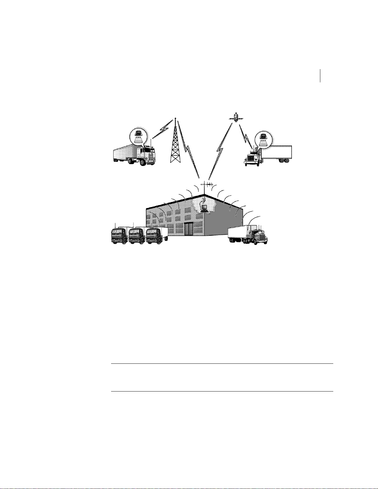
Figure1 Fleetlink Solution
FLEETLINK DRIVER DISPLAY FOR TRUX
User Guide
13
How Communication Works
As illustrated in Figure1 above, communication between your vehicles and the Fleetlink
server is possible using short-wave radio, which is standard in all configurations, and
terrestrial or satellite radio, both of which are optional. This wireless transfer of data
without human intervention is one of the main benefits of the Fleetlink solution.
Inside the yard, short-range radio is used to send information to and from the vehicles. At
the start of the day, route information is downloaded to the vehicles; at the end of the day,
vehicular data and driver information are uploaded to the Fleetlink server. When vehicles
are outside of this zone, optional wireless communication—terrestrial or satellite radio—
can be used to transmit selected information to and from the vehicles.
Note If the Fleetlink server fails, communication between the terminal and vehicles will be
impossible. However, drivers will still be able to use the Driver Display and the OBC will
continue to store information.
Page 15
CHAPTER 2
14
Introduction
Introducing the Driver Display
The driver display is the interface between drivers and your company’s terminal, and
includes a monochrome display and a keyboard. It allows you to confirm calls and enter
activities. When optional terrestrial or satellite radio communication is equipped, the
driver display can also be used to maintain constant communications with your
dispatcher.
Information entered by drivers is recorded by the OBC, which uploads it to the Fleetlink
server wirelessly. In standard RF-only configurations, information is uploaded to the
server when the vehicle comes into range. When communication via terrestrial or satellite
radio is available, selected information, such as completed calls, can also be uploaded in
real-time.
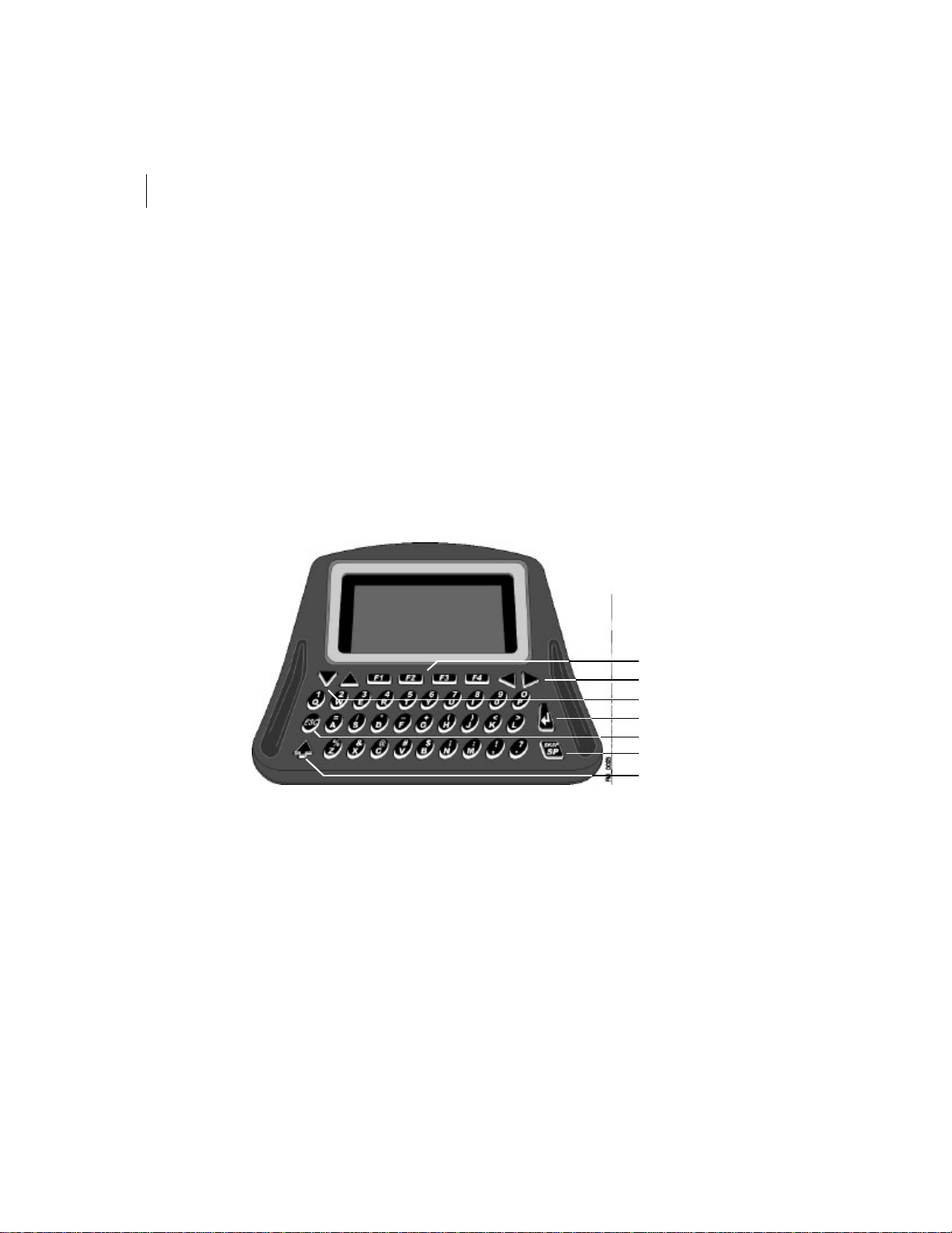
Figure2 Driver Display
Function Keys
Horizontal Arrows
Vertical Arrows
Enter
Escape
Space/Backspace
Shift
Page 16

FLEETLINK DRIVER DISPLAY FOR TRUX
15
User Guide
Working with the Driver Display
Working with the Keyboard
The driver display’s keyboard includes several keys (see figure2on page14), with special
functions (see table below).
Table1 Special keys
Key Function
Horizontal arrows Use to navigate left or right through fields. Also use to
Vertical arrows Use to navigate up or down through fields. Also use to
Escape Use to return to the previous menu.
Space/Backspace Use to add a space between characters. Press the Shift
Enter Use to confirm data entry and proceed to the next step.
Shift Use to access special functions or characters. Press once
Function keys Use these keys to access the functions that are
change the value in a scrolling list.
change the value in a scrolling list.
key before pressing this key, and you will erase the
character to the left of the cursor.
for a single function or character. Press twice to lock shift
function; the key lights up. To turn off shift lock, press the
key again.
represented by abbreviations at the bottom of the screen.
Note that when there is no abbreviation indicated above a
key, the key is inactive.
Page 17
CHAPTER 2
16
Introduction
Working with the Screen
The screen of the driver display has a capacity of 8 lines by 21 characters in text mode. The
driver display uses the following conventions:
• Scrolling list: To indicate a scrolling list, the screen uses either vertical or
horizontal arrows.
• Active function key: When a function key is active, the screen displays an
abbreviation directly above the key. This abbreviation indicates the key’s
function.
• Inactive function key: When there is no abbreviation displayed above a function
key, the key is inactive.
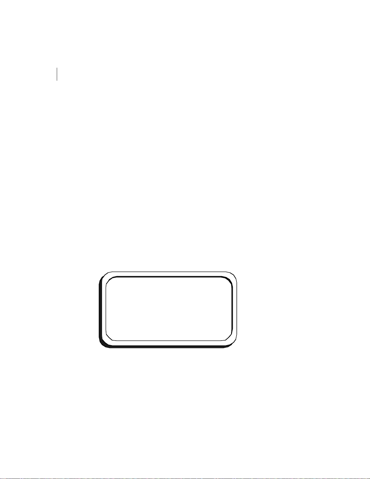
Understanding the Main Menu
The main menu (see Figure3) provides access to all submenus and functions. It appears
automatically after you logon (see “Logging On” on page20 for procedure). To navigate
through the available submenus, use the arrows on the display’s keyboard. To select a
submenu, simply navigate to the desired menu and press Enter. To return to the main
menu at any time, press ESC.
Figure3 Main Menu
[Calls]
[Call-In]
[Message]
[Disposal Ticket]
[Activities]
[End of route]
STAT
MENU
100
Page 18

FLEETLINK DRIVER DISPLAY FOR TRUX
17
User Guide
Tip The main menu includes a counter of unconfirmed or pending calls. During the
download of route information to the vehicle, this counter increases until all calls have
been downloaded. Once the download is complete, the function key STAT becomes active
(see Figure3 above). The presence of the STAT function key is your indicator that all
information has been downloaded and that you can safely start your route. As you confirm
calls along your route, the call counter in the main menu will decrease accordingly.
Viewing Statistics
The STAT function key provides access to such information as number of unconfirmed
calls and number of customers cancelled (see Table2 below for complete list).
Note The STAT function key becomes active once route information has been successfully
downloaded to the vehicle.
Table2 Statistics
Name Description
Calls Number of unconfirmed calls
CustCncl Number of customers canceled
Lifts Number of lifts
New Number of new calls
No Serv Number of “No services”
NTW Number of “Not this week”
ServSusp Number of suspended services
SiteCncl Number of sites cancelled
Stops Number of stops
WO Number of work orders
Yards Number of yards
Page 19

CHAPTER 2
18
Introduction
Vehicle moving and Screen Behavior
When the vehicle is in motion, you cannot access the various menus of the Driver Display.
As soon as the vehicle stops or falls below the speed threshold of 20 km per hour, an OK
function key becomes active. Press this key to continue using the driver display.
Page 20

Chapter 3
Operation
Page 21
CHAPTER 3
20
Operation
Introduction
In Chapter 2 “Introduction”, you learned general information about the Driver
Display and how it is used. In this chapter, you will become familiar with detailed
procedures for logon and logoff, confirming calls, entering driver activities, among
others. Note, however, that the procedures presented are specific to use with
TRUX back-office applications. If your back-office application is Soft-Pak, refer to
the appropriate Driver Display user guide for Soft-Pak.
Logging On
Unlike other menus, which must be selected from the main menu of the driver display, the
Activation or logon screen appears as soon as you key on. Before you begin your route, you
must logon.
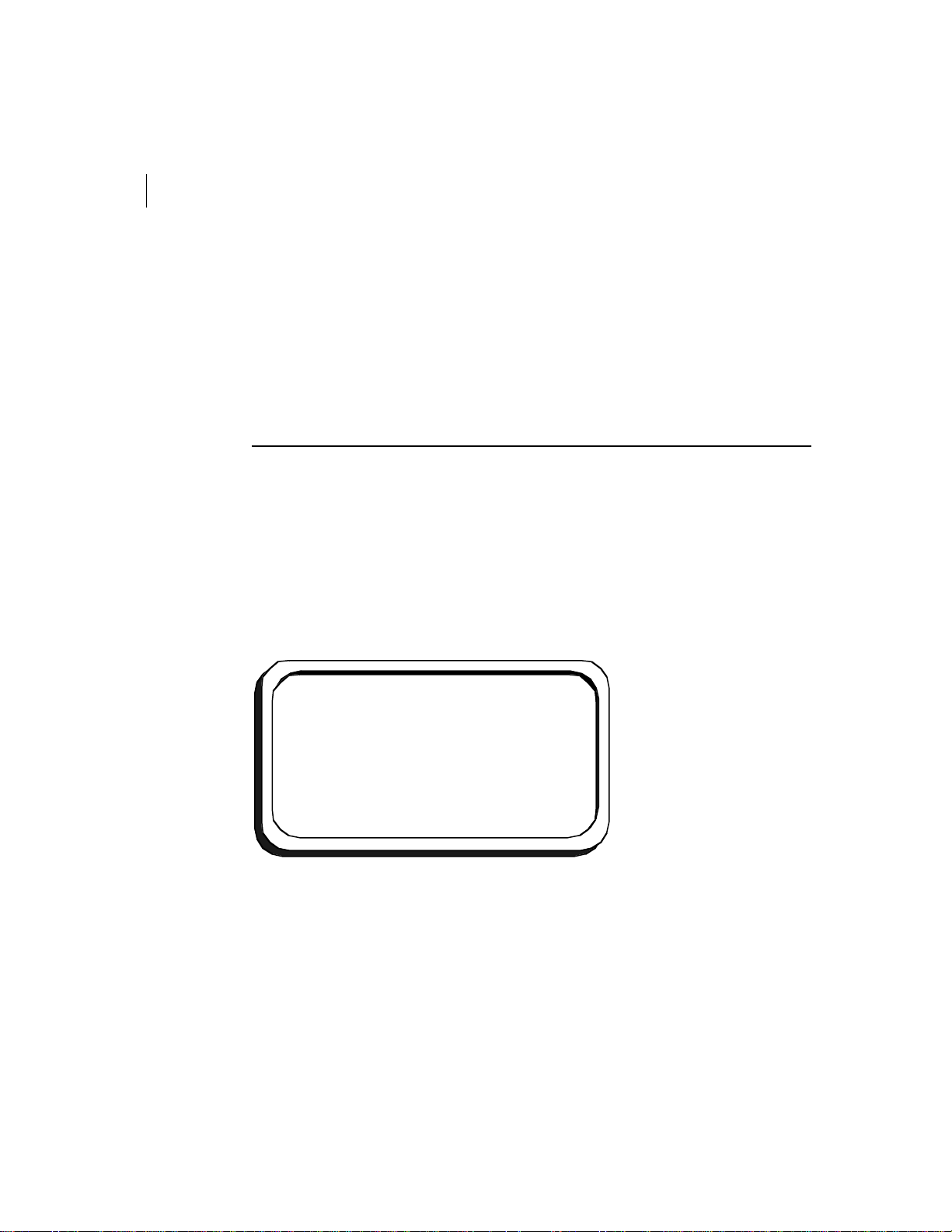
Figure1 Activation (Logon) Screen
Driver:
Odometer: 10000
Time: 8:00
ACPT
ACTIVATION
Page 22

FLEETLINK DRIVER DISPLAY FOR TRUX
User Guide
To logon:
1 Enter your driver ID or employee number.
Note Driver IDs can include numbers or letters, or both.
2 Verify the odometer and time on the driver display. Inform the dispatcher of any
significant differences.
3 Press F2 (ACPT) to accept.
21
Page 23

CHAPTER 3
22
Operation
Working with the Calls Menu
The Calls menu displays a list of the calls that make up your route, with each line
representing a call.
To access the Calls menu:
• From the main menu, navigate to Calls using the arrow keys and press Enter.
Figure2 Calls Menu
CALLS
Smith & Son
Waste Tech.
Future Corp.
Chem. Industries
National Construction
seq. search #
PREV NEXT SRCH
10.00
13.00
50.00
55.00
65.00
To scroll through the list of calls, use the vertical arrows on the keyboard.
Note Up to 30 calls can be displayed at a time. When there are more than 30 calls, the
F1 (PREV) and F2 (NEXT) function keys allow you to view the previous and next set of
calls.
Page 24
FLEETLINK DRIVER DISPLAY FOR TRUX
23
User Guide
Viewing Call Information
To view the details of a call:
• From the Calls menu, navigate to the desired call using the arrow keys and press
Enter.
Tip The search function allows you to find a call quickly using its sequence number. This
saves you from scrolling through the list of calls. For information, see “Searching for Calls
by Sequence Number” on page25.
The driver display will show the first of four information screens (see Figure3 through to
Figure6). You will notice that the top of the screen includes the call’s sequence number, as
well as the number of the information screen currently displayed. To navigate through the
information screens, use the F1 (PREV) and F2 (NEXT) function keys.
Figure3 INFO1 Screen
13.00
Cust: 001122
Site: 0001 Serv: 001
East End, 200 Main St.
NEXT CONF
INFO1
Page 25
CHAPTER 3
24
Operation
Figure4 INFO2 Screen
13.00
Lft: 1.00
Serv:
Acti:
Work Order:
Reference:
PREV
NEXT CONF
Figure5 INFO3 Screen
13.00
Schedule:
Mon Wed Fri
Site Notes:
PREV
NEXT CONF
Figure6 INFO4 Screen
INFO2
Size: 6.00
INFO3
13.00
Service Notes:
Work Order Notes:
PREV
INFO4
CONF
Page 26

FLEETLINK DRIVER DISPLAY FOR TRUX
25
User Guide
Searching for Calls by Sequence Number
The Calls menu includes a search function (see Figure2on page22) that allows you to find
a call using its sequence number. This saves you from scrolling through the list of calls.
To search for a specific call:
1 From the Calls menu, press the right arrow to access the search function.
2 At the prompt, enter the sequence number of the desired call, including any decimals
and press F3 (SRCH). If a match is found it will appear highlighted in the call list. If
there is no match, the screen will remain unchanged.
Note The Search function remembers the last sequence number searched. To perform a
new search, first use the BKSP key to clear the field and then enter the desired sequence
number.
Note When searching for sequence numbers that include decimals, Fleetlink searches first
by the number before the decimal, and then refines its search by searching for the number
after the decimal. If a match is found only for the first part, Fleetlink will return the first
occurrence in the call list.
Tip To exit the search function without searching for a call, press the up arrow.
Page 27
CHAPTER 3
26
Operation
Confirming Calls
As you complete calls during your route, you must confirm them. This information tells
the dispatcher that you have completed the call and is used to build your trip sheet. It also
provides office personnel with key information about how much waste is collected for each
customer.
To confirm a call:
1 From a Call Info screen, press F3 (CONF) to access the Confirm screen.
Figure7 Call Confirmation Screen
13.00
Lifts: 1.00
Work Order:
Activity Code:
Regular Service
Reference:
Notes:
WGT
DISP ACPT
CONFIRM
2 Verify the number of containers or lifts. Correct, if necessary.
3 Use the arrow keys to navigate to the Activity Code field and select the desired code.
Note If No List appears under Activity Code, contact the office to have the list
uploaded.
4 If necessary, enter additional information under Notes (e.g., “container blocked by
parked vehicle”).
5 Press F1 (WGT) to enter the weight of the container. If you have an on-board scale
direct connected (integrated), wait a few seconds for the reading. Otherwise, enter the
weight manually. Use the arrow keys to change the measurement unit, if necessary. If
there are other containers, press F2 (NEXT) and repeat this step. When you have
entered the weight for all containers, press F3 (ACPT) to accept and to return to the
Confirm screen.
Page 28

FLEETLINK DRIVER DISPLAY FOR TRUX
27
User Guide
6 In the Confirm screen, press F4 (ACPT) to confirm the call.
Caution You must enter the weight of each container before you confirm the call. Once a
call is confirmed, you cannot go back to enter any weights.
Once you have confirmed a call, it disappears from the list in the Calls menu.
Page 29

CHAPTER 3
28
Operation
Creating New Calls
The Call-In menu allows you to create new calls during your route. This is useful when the
dispatcher informs you of an additional call after you have already left the yard.
To create a new call during your route:
1 From the main menu, navigate to Call-In using the arrow keys and press Enter. This
will display the first of four call information screens identical to those shown in
Figure3 through to Figure6 in “Viewing Call Information” on page23.
2 In the first Info screen, use the arrow keys to navigate to the sequence number field
and enter a sequence number. Press F2 (NEXT) to access the second Info screen.
3 Using the arrow keys, navigate to the number of lifts field and enter the number of
lifts.
4 Using the arrow keys, navigate to the size field and enter the size of the container.
5 Enter any other available information about the new call. Use the F1 (PREV) and F2
(NEXT) function keys to navigate through the information screens and the arrow keys
to navigate through the fields.
6 Press F3 (REC) to save the call.
Note Make sure you enter a sequence number so that you can locate the call later in the
call list.
Once you have finished creating a new call, it is added to the list of calls in the calls menu.
For information on viewing call information, searching for calls and confirming call, see
“Working with the Calls Menu” on page22.
Page 30
FLEETLINK DRIVER DISPLAY FOR TRUX
29
User Guide
Entering Disposal Tickets
The main menu selection called Disposal Ticket gives you access to two Disposal Ticket
screens that allow you to enter information about the waste you unload at the landfill or
other facility. This information tells office personnel how much waste was unloaded each
trip. This can be very valuable when your compagny wants to compare your disposal costs
to your customer billing.
To enter a disposal ticket:
1 From the main menu, use the arrow keys to navigate to Disposal Ticket and press
Enter.
2 In the first disposal ticket screen, enter the ticket number, as well as the weight and
sequence, if applicable.
Figure8 First Disposal Ticket Screen
DISPOSAL TICKET
Ticket #:
Weight:
Sequence:
NEXT
3 Press F2 (NEXT) to access the second Disposal Ticket screen.
4 In the second disposal ticket screen, enter the facility and the material.
1/2
Page 31
CHAPTER 3
30
Operation
Figure9 Second Disposal Ticket Screen
DISPOSAL TICKET
Facility:
Alternative Recycling
Material:
Waste
ACPTPREV
2/2
5 When you have finished entering the information, press F3 (ACPT).
Page 32
FLEETLINK DRIVER DISPLAY FOR TRUX
User Guide
Sending Messages
The main menu selection called Message allows you to send messages of up to
105characters, including spaces, to the dispatcher.
To send a message:
1 From the main menu, navigate to Message using the arrow keys and press Enter.
Figure10 Send Message Screen
SEND MESSAGE
To:
SEND
31
2 Enter the name of the recipient and press Enter.
3 Type your message and press F2 (SEND).
Page 33

CHAPTER 3
32
Operation
Viewing Messages
You can view messages sent to you by the dispatcher by pressing F4 (MSGS), which is
accessible from the main menu, as well as from the Calls and Activities menus1.
Tip Whenever you receive a new message, an exclamation point appears to the right of
MSGS on the screen.
To view messages in your message box:
1 From either the main, Calls or Activities menu, press F4 (MSGS) to access your
message box. The first received message will automatically appear.
2 Use the F1 (PREV) and F2 (NEXT) function keys to view other messages.
3 To delete a message, navigate to the message and press F3 (DEL).
Note If you delete all messages in your message box, the F4 (MSGS) function key will
become inactive until you receive a new message.
Note Any messages remaining at the end of your day are automatically deleted upon
logoff.
1 The F4 (MSGS) function key is only active when there are messages in your message box.
Page 34
FLEETLINK DRIVER DISPLAY FOR TRUX
33
User Guide
Entering Activities
The Activities menu allows you to enter activities, such as meals and refueling, which help
complete your trip sheet. An activity represents a task, which has a beginning and an end,
or an event. Some activities, such as breaks, prevent you from starting another activity or
from confirming a call until they are ended. These activities are called blocking activities.
Other activities, such as gate crossings, are simply recorded as an occurrence in time. These
activities are referred to as events.
Figure11 Activities Menu
ACTIVITIES
Gate crossing
Meal
Break
Refueling
Note The Activities menu shown above includes common activities. Your available
activities may differ based on your configuration.
Page 35
CHAPTER 3
34
Operation
To enter an activity:
1 From the main menu, navigate to Activities using the arrow keys and press Enter.
2 Use the arrow keys to navigate to the desired activity and press Enter. If the selected
activity is an event, such as gate crossing, the main menu will appear. You may skip
the following steps. However, if the selected activity is a blocking activity, such as
meal, break or refueling, a screen similar to the one screen in Figure12 will appear.
You must proceed to step 3.
Figure12 Current Activity Screen (Meal)
CURRENT ACTIVITY
Meal
Since:
Elapsed:
END
12:00
00:35
3 When you have completed the activity, press F1 (END). This will close the activity and
return you to the Activities menu.
Page 36
FLEETLINK DRIVER DISPLAY FOR TRUX
35
User Guide
Logoff
At the end of the day, you must logoff. This tells the dispatcher that you have completed
your route and updates the information in your trip sheet.
However, to make sure that your information is properly uploaded to the Fleetlink server,
do not logoff until you are back in the yard and in RF range. When you logoff, Fleetlink
actually delays the logoff by 60 minutes as an extra precaution to ensure that information
has sufficient time to be uploaded to the server.
Caution Before you logoff, make sure that you have confirmed all calls. Calls that are not
confirmed when you logoff will be erased.
To logoff:
1 From the main menu, navigate to End of Route using the arrow keys and press Enter.
Figure13 End of Route Menu
END OF ROUTE
Is your route
finished?
Odometer: 10150
Distance: 150
Time: 17:00
2 Verify the odometer reading and the time. Inform the dispatcher of any significant
differences.
3 Using the arrow keys, select Yes and press Enter.
[NO]
[YES]
Page 37

36
NOTES
Page 38

Fleetlink
Hardware Installation and
Configuration Guide
Page 39

© 2002, 2003 FleetMind Solutions Inc. All rights reserved.
Fleetlink Hardware Installation and Configuration Guide
The information contained in this manual is subject to change without notice. All statements, information and
recommendations in this manual are believed to be accurate, but are presented without warranty of any kind,
express or implied. Users must take full responsibility for their use of any products.
No part of this publication may be reproduced or transmitted in any form or by any means, electronic or mechanical,
including photocopying and recording without prior written consent from FleetMind Solutions Inc.
The FleetMind and Fleetlink logos and designs are trademarks of FleetMind Solutions Inc. All other trademarks are
the property of their respective owners.
The license agreement is contained within the software’s installer.
FleetMind Solutions Inc., 455 Fénelon Blvd., Suite 110, Dorval QC H9S 5T8, CANADA
Document Part Number: 33-911-0002-01.C (0304)
Page 40

Preliminaries Chapter 1
Welcome.................................................................................. 6
Important Safety and Compliance Information ........................ 6
Using the Documentation........................................................ 8
Service and Support.............................................................. 10
Contacting Us........................................................................ 10
Preinstallation Chapter 2
Introduction............................................................................ 12
Unpacking the Fleetlink Components.................................... 12
Safety Recommendations ..................................................... 14
Tools Required ...................................................................... 14
Installation Chapter 3
Introduction............................................................................ 16
Standard and Optional Components ..................................... 16
Installation Tips...................................................................... 19
Installing Antennas ................................................................ 20
Connecting the Deutsch Connector Harness ........................ 24
Installing the Copilot in Pulse-measured Vehicles................. 27
Installing the Junction Box..................................................... 33
Installing the Copilot .............................................................. 34
Installing the Driver Display................................................... 38
Installing the Bar Code Scanner............................................ 40
CONTENTS 3
Configuration Chapter 4
Introduction............................................................................ 42
Preparation............................................................................ 42
Configuring the Copilot .......................................................... 43
Verifying the Vehicle’s RPMs ................................................ 48
Verifying the GPS Status Reading ........................................ 49
Page 41

CONTENTS4
Specifications Appendix 1
Fleetlink Component Specifications ....................................... 52
In-Vehicle Installation Appendix 2
Introduction............................................................................ 58
Installing the Antennas .......................................................... 58
Installing the Deutsch Connector Harness ............................ 65
Installing Driver Display and JunctionBox............................. 68
Installing the Copilot .............................................................. 71
Page 42

Chapter 1
Preliminaries
Page 43

CHAPTER 1
6
Preliminaries
Welcome
Welcome to Fleetlink, which provides a complete picture of what’s happening
across your fleet. The Fleetlink On-board Computer (OBC), which is also referred
to as the Copilot, captures and records vehicular data, such as speed, RPM and
fuel consumption, from a variety of sources. This manual is divided into four
chapters (see “Using the Documentation ” in this chapter), which will guide you
step-by-step through the various tasks of preparing, installing and configuring the
Fleetlink Copilot. It also includes two appendices, which provide detailed
equipment specifications and practical installation tips.
Important Safety and Compliance
Information
Note This section applies to the Fleetlink M1 OBC model, specifically model S-M1-10
Fleetlink M1 OBC Short-Range RF without Terminal and S-M1-10-T Fleetlink M1 OBC
Short-Range RF with Terminal.
Before you install or use the Fleetlink product, read the FCC and other regulatory material
found below, as well as in the other documents that accompanied your order.
This section provides information on the following topics:
• FCC compliance statement (USA)
• Industry Canada Certification
Warning To meet FCC/IC RF exposure guidelines, you must keep at least 8in. (20 cm.)
from the antenna during operation.
Page 44

FLEETLINK
Hardware Installation and Configuration Guide
7
FCC Compliance Statement (USA)
This equipment has been tested and found to comply with the limits for a Class A digital
device, pursuant to Part 15 Subpart B of the FCC Rules. These limits are designed to
provide reasonable protection against harmful interference in a commercial, industrial or
business environment. This equipment generates, uses, and can radiate radio frequency
energy and, if not installed and used in accordance with the product manuals, may cause
harmful interference to radio communications. Operation of this equipment in a residential
area is likely to cause harmful interference in which case users will be required to correct
the interference at their own expense. This equipment also complies with the FCC Part 15
Subpart C.
Caution Changes or modifications to this unit not expressly approved by the party
responsible for compliance could void your authority to operate this equipment.
Industry Canada Certification
This Class A digital apparatus complies with Canadian ICES ICES-003 and RSS 210.
Page 45

CHAPTER 1
8
Preliminaries
Using the Documentation
This publication assumes a basic familiarity with transport vehicles and radio installation.
It is designed for persons who are responsible for the installation of the Fleetlink
components, such as mechanics. It is divided into the following four chapters, which are
arranged in order of the complexity of the information:
1 Preliminaries
Provides general information about the manual, safety and compliance information,
as well as information on how to contact customer support.
2 Preinstallation
Provides an overview of the Fleetlink Copilot components, as well as safety measures
to consider during installation and tips on how to prepare for installation.
3 Installation
Provides instructions on how to install the Fleetlink Copilot.
4 Configuration
Describes how to configure Fleetlink Copilot once installed.
In addition to the above, this manual also includes the following two appendices:
1 Specifications
Provides detailed specifications for the various components.
2 In-Vehicle Installation
Provides practical tips on installation.
Page 46

FLEETLINK
Hardware Installation and Configuration Guide
Conventions
This publication uses the following conventions to convey instructions and information:
Table1 Hardware Installation and Configuration Guide Conventions
Convention Description
> The arrow indicates a menu choice. For example, select
File>Save means select the File menu, then select the Save
command on the File menu.
Click Clicking the left mouse button.
Right-click Clicking the right mouse button.
Ctrl-click Holding down Ctrl and clicking the left mouse button.
Ctrl-right-click Holding down Ctrl and clicking the right mouse button.
Double-click Clicking the left mouse button twice.
Caution Indicates reader be careful. In this situation, you might do
something that could result in equipment damage or loss of data.
Note Indicates reader take note. Notes contain helpful suggestions or
references to additional information and material.
Tip Indicates that the described action saves time.
9
Suggested Reading
For related information, see the following publications:
• Fleetlink Report Manager User Guide, 33-911-0001-01
• Fleetlink Administrator Guide, 33-911-0003-01
• Fleetlink Access Point 300 Installation Guide, 33-911-0004-01
• Fleetlink Driver Display for TRUX User Guide, 33-911-0005-01
• Fleetlink Driver Display for Soft-Pak User Guide, 33-911-0006-01
Page 47

CHAPTER 1
10
Preliminaries
Service and Support
If you require assistance with this or any other FleetMind product, please call or email
technical support.
Call for Assistance:
Greater Montreal Area: 514.631.3666, ext. 250
Toll-free North America: 1.877.698.4286, ext. 250
Email for Assistance:
Contacting Us
If you have comments about this or other FleetMind product documentation, send us an
email at [email protected]. In your message, be sure to include the manual's
complete document number and revision letter (e.g., 001-000001-011, Rev. A), which you
can find on the back cover. We appreciate your comments.
Page 48

Chapter 2
Preinstallation
Page 49

CHAPTER 2
12
Preinstallation
Introduction
Fleetlink is an easy-to-use on-board computer (OBC) combined with management
software for dispatch and operations staff. The on-board computer or Copilot
communicates vital route information to the driver via a driver display. It also
sends vehicle, driver activity, GPS coding, and trip record information back to the
office through a variety of wireless links, including a short-range, in-yard system
with no airtime charges. In this chapter, you will become familiar with Fleetlink
components and learn about necessary tools and safety precautions.
Unpacking the Fleetlink Components
When you unpack your installation kit—
• Check all items against your shipping order to ensure that you have received all
the components. If a component is missing, contact customer support.
• Inspect the equipment for visible shipping damage. If you notice any damage,
contact customer support.
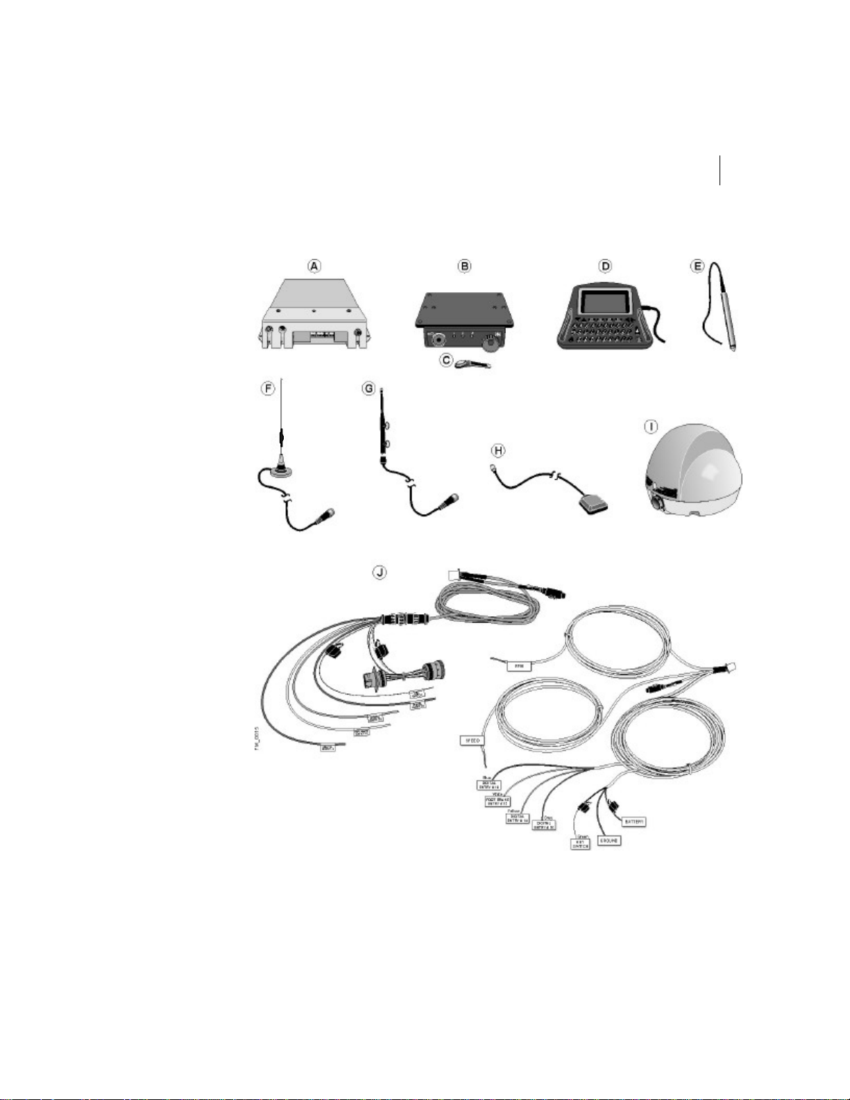
Your Fleetlink installation kit includes the following components:
A Copilot
B Junction box
C Dallas key (optional)
D Driver display and support (optional)
E Bar code scanner and support (optional)
F WAN antenna (optional)
G LAN antenna
H GPS antenna
I Satellite antenna (optional)
J One of the following: 1. Deutsch connector harness and ECM cable or 2. Pulse
cable
Page 50
Hardware Installation and Configuration Guide
Figure1 Fleetlink Components
FLEETLINK
13
Page 51

CHAPTER 2
14
Preinstallation
Safety Recommendations
Before installing Fleetlink, please review the following guidelines to protect the equipment
and ensure your safety.
• Turn off the vehicle.
• Make sure that the parking brake is fully engaged.
• Disconnect the vehicle’s battery prior to connecting any wires to the vehicle’s
power supply.
Tools Required
Make sure you have the following tools on site before installing Fleetlink:
• Jumper cable with alligator clip
• Drill
• 3/4 inch-diameter drill bit
• Multimeter
• Phillips screwdriver
• Pulsemeter
• Scotch lock
• Tie-wraps
• Weather-resistant sealant or calking
Page 52

Chapter 3
Installation
Page 53

CHAPTER 3
16
Installation
Introduction
Fleetlink is designed to suit almost all makes of trucks; however, the location of a
component may vary slightly from one truck to another. This chapter explains how
Fleetlink components interconnect, and provides step-by-step procedures for the
most common types of installation.
Standard and Optional Components
Fleetlink consists of standard and optional components. In a standard configuration, the
components are:
• Copilot
• Junction box
• One of the following: 1. Deutsch harness connector and ECM cable or 2. Pulse
cable
• LAN antenna
• GPS antenna
• One of the following: 1. Driver display and support or 2. Dallas key
The optional components are:
• Bar code reader and support
• WAN antenna
• Satellite antenna
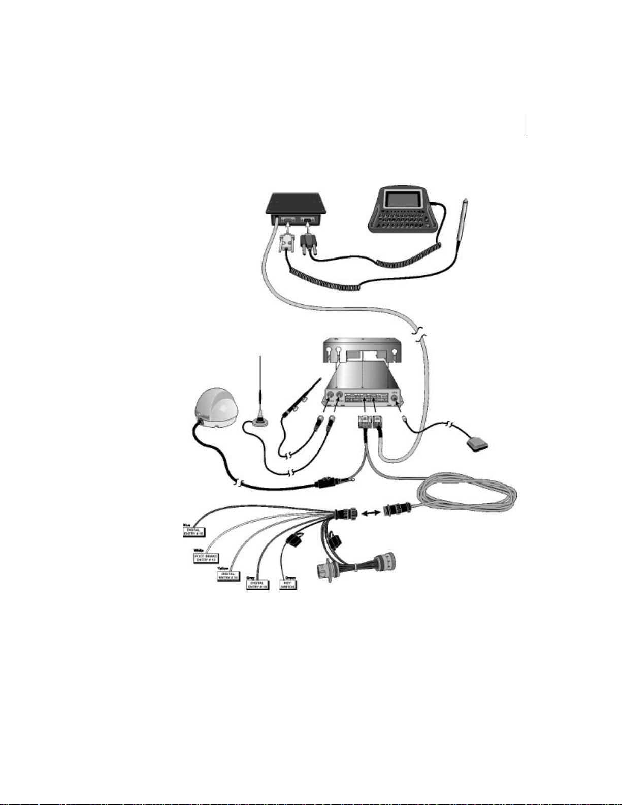
Figure2on page17 shows how the Fleetlink components, both standard and optional,
interconnect.
Page 54
FLEETLINK
Hardware Installation and Configuration Guide
Figure2 Fleetlink Components (Deutsch harness connector and ECM cable shown)
17
Page 55

CHAPTER 3
18
Installation
The following sections describe the Fleetlink installation procedures and their
recommended installation location:
• “Installing Antennas” on page20
• “Connecting the Deutsch Connector Harness” on page24
• “Installing the Copilot in Pulse-measured Vehicles” on page27
• “Installing the Junction Box” on page33
• “Installing the Copilot” on page34
• “Installing the Driver Display” on page38
• “Installing the Bar Code Scanner” on page40
Your Fleetlink package may not include all of these components. Refer to your packing slip
for a complete list of shipped components.
See Appendix 2, “In-Vehicle Installation” on page57 to view a sample installation.
Page 56

FLEETLINK
19
Hardware Installation and Configuration Guide
Installation Tips
Depending on the truck model in which you install the Fleetlink components, you may
choose to vary the order for your installation. You may also choose to install the
components, such as the Copilot or junction box, in places other than those suggested in
this guide.
FleetMind provides you with the following tips, based on our experience with
installations:
• The Copilot is the main Fleetlink component. You must install the other Fleetlink
components within a 5-metre cabling distance of the Copilot.
• FleetMind recommends that you install the Copilot inside the dashboard.
However, you can also install it under the passenger’s seat or behind the middle
console.
• When you install the Copilot, junction box, driver display support and bar
scanner support, you can use the equipment as a template to determine where to
drill the holes.
• You must leave sufficient slack in the cables of the components connected to the
Copilot to ensure that they will not be pulled tight by the vibrations of the vehicle
and therefore risk becoming disconnected.
• After installing and testing the components (see “Configuring the Copilot” on
page43), neatly fold back any excess cables behind the glove compartment or in
the dashboard and secure with plastic tie-wraps. Clip any excess tie-wrap.
• Fleetmind recommends that you drill the hole for the antenna cables into the back
wall of the cab and not into the floor. This will minimize damage to the vehicle
due to water corrosion.
Page 57

CHAPTER 3
20
Installation
Installing Antennas
Fleetlink currently offers four types of wireless communication requiring different types of
antennas:
• LAN
• GPS
• WAN (Mobitex or iDEN)
• Satellite
The LAN antenna provides the short-range, in-yard radio link, which is standard to all
configurations. The other antennas you install will depend on your chosen configuration.
For the installation of the GPS, WAN and satellite antennas, FleetMind recommends the
following:
• Drill the hole through which you will pass the antenna cable in the cab’s rear
wall. Drilling a hole in the rear wall rather than through the cab floor will reduce
the risk of water damage and unnecessary wear and tear.
• Ensure that the area receiving an exterior antenna is clean and dry. If the area is
dirty or greasy, the antenna may become unstuck.
• Drill only one 3/4 inch-diameter hole into the back of the cab. A hole of this size
is sufficient for both antenna cables.
• Use tie-wraps to tie exterior cables together at regular intervals (approximately
four inches). Clip any excess.
• Use a drip loop to ensure that water will drip off the antenna cables and not run
into the cab.
Page 58

FLEETLINK
21
Hardware Installation and Configuration Guide
Installing the LAN Antenna
Make sure you install the LAN antenna in a location where it will not disturb the driver or
interfere with another mechanism within the cab of the vehicle if it becomes unstuck. The
recommended location for the LAN antenna is inside the cab, vertically positioned in the
lower right-hand corner of the windshield.
Caution The Fleetlink Copilot is designed to operate with an antenna having a maximum
gain of 3 dB. Antennas having a higher gain are strictly prohibited per regulations of
Industry Canada. The required antenna impedance is 50 ohms.
Warning To meet FCC/IC RF exposure guidelines, you must keep at least 8in. (20 cm.)
from the antenna during operation.
To install the LAN antenna:
1 Select the desired location for the antenna inside the cab.
2 Remove panelling as required.
3 Clean the windshield area where the antenna will be mounted with an alcohol wipe or
equivalent method.
4 Gently warm the windshield with a hair dryer, or 12V defroster blower, if the
temperature is below about 15 deg. C.
5 Put a drop of adhesive on each suction cup. Press and hold the antenna to the
windshield for the time indicated in the adhesive instructions. Consult FleetMind
customer Service for recommended adhesives.
6 Pass the antenna cable through to the location where the Copilot will be installed.
7 Connect the LAN antenna cable to the Copilot following the procedure: “Installing the
Copilot” on page34.
Page 59
CHAPTER 3
22
Installation
Installing Exterior Antennas
The Fleetlink solutions supports three types of exterior antennas:
• WAN (Mobitex and iDEN)
• GPS
• Satellite
When installing the exterior antennas:
• Make sure the antenna and its cable cannot come into contact with the vehicle’s
exhaust pipe. If necessary, you can pass it safely behind the pipe bracket and
fasten it there.
• Install the antenna on the roof of the cab.
• Move any accessories that might interfere with passing the cable safely from the
roof through the cab.
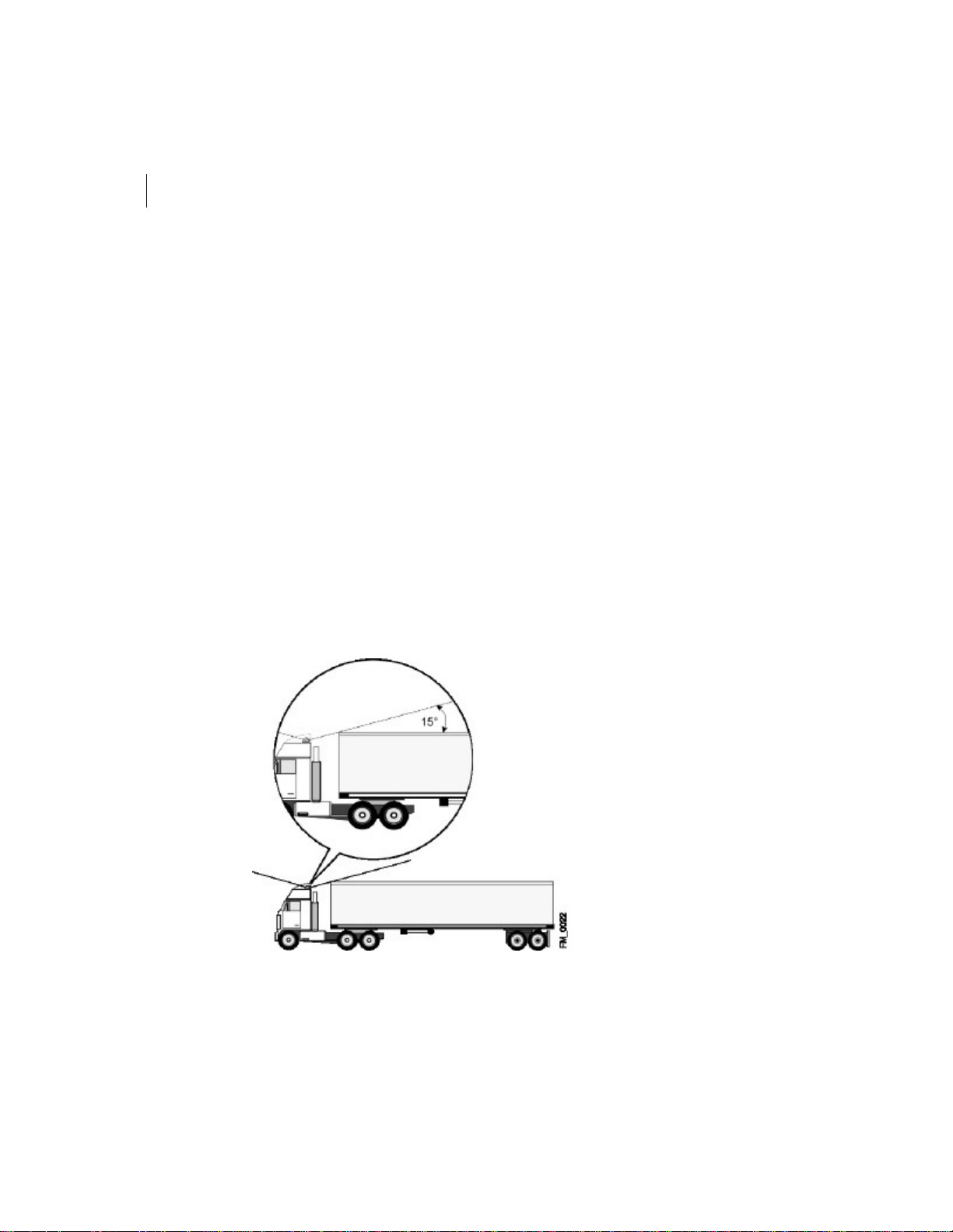
• Ensure a minimum of 15% angle clearance when installing a satellite antenna (see
Figure3).
Figure3 Installation for Satellite Antenna
FM_0022.eps
Page 60

FLEETLINK
23
Hardware Installation and Configuration Guide
Note You cannot have a WAN and a satellite antenna on the same Fleetlink installation.
To install an exterior (GPS, WAN or satellite) antenna:
1 Select the locations on the cab’s roof where you will install the antennas. Clean the
selected areas to ensure that the antennas will stick well to the surface.
2 Position the antenna on the cab roof, making sure to place it away from other
antennas.
3 Select a spot on the cab’s rear wall through which you will pass the antenna cable.
Make sure that drilling this area will not damage anything inside the cab.
4 Remove the panelling inside the cab where you will drill the hole and through which
you will pass the antenna cables. This is usually the panelling behind the passenger
seat and above the passenger door.
5 Drill a 3/4 inch-diameter hole into the back of the cab.
6 Install the seal on the cab.
7 Pass the antenna cable through the hole into the corner of the cab, around the
passenger side of the cab, above the passenger door and through the dashboard to the
Copilot.
8 Ensure that water cannot seep through the seal by letting the cable hang a little below
the level of the seal.
9 Seal the space between the cable and the seal using a weather-resistant sealant or
calking.
10 Connect the antenna cable to the Copilot following the procedure “Installing the
Copilot” on page34.
Page 61
CHAPTER 3
24
Installation
Connecting the Deutsch Connector
Harness
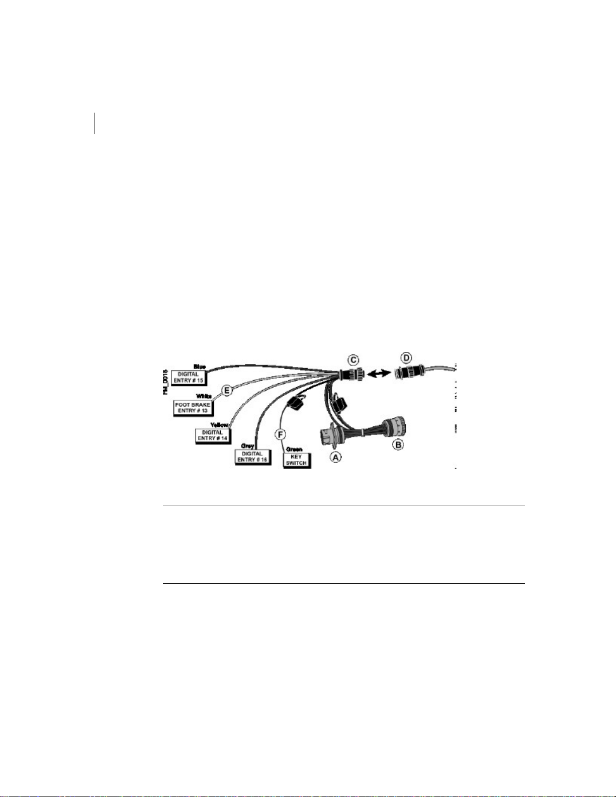
When you install the Deutsch connector harness, you connect it to the—
• Vehicle’s ECM.
• Key switch wire.
• Foot brake wire.
The Deutsch connector harness is also equipped with three wires so that you can take
readings for additional digital inputs, such as PTO.
Figure4 Connecting the Deutsch Connector Harness
Warning In vehicles manufactured by Peterbuilt, the ignition wire is encased in the cable
leading to the diagnostic connector that connects to the vehicle’s ECM. You must cut open
the cable and disconnect the ignition wire from the diagnostic connector. You must then
connect the ignition wire to the ignition/key switch wire of the OBC cable as described in
this procedure. If you connect the diagnostic connector to the Deutsch connector harness
without disconnecting the ignition wire, you may damage the Copilot.
Page 62

FLEETLINK
25
Hardware Installation and Configuration Guide
To install the Deutsch connector harness:
1 Unscrew the fuse box under the dashboard on the driver’s side.
2 Lower the fuse box completely. This will allow you to insert the Deutsch connector
harness under the dashboard.
3 Plug the vehicle’s diagnostic connector into the Deutsch harness connector (A).
4 Clip the Deutsch harness connector into the designated bracket in the vehicle.
5 Plug the ECM cable connector (D) into the corresponding jack of the Deutsch
connector harness (C).
6 Leave the fuse box unscrewed and proceed to connect the key switch and brake signal
wires.
To connect the key switch wire:
1 Locate the vehicle’s key switch wire. The key switch wire transmits the starter signal
(i.e., the On position).
2 Connect a multimeter to the key switch wire.
3 Turn the key switch to the Accessories position.
4 Verify that the multimeter reading is 0 VDC.
5 Turn the key switch to the On position.
6 Verify that the multimeter reading is 12 VDC or more.
7 Connect the green wire of the Deutsch connector harness to the vehicle’s key switch
wire.
8 Verify that the multimeter reading is 12 VDC or more. It is important that you are not
connected to the accessories circuit, so that you have a constant signal when starting.
Page 63

CHAPTER 3
26
Installation
To connect to the service brake signal sire:
1 Locate the service brake signaling wire.
2 Connect a multimeter to the service brake signaling wire.
3 Apply the service brakes.
4 Verify that the multimeter has a reading of 12 VDC or more.
5 Connect the white foot brake wire to the service brake signaling wire.
Note On some vehicles, the position lights may be on the same circuit. If so, you must
install a pressure switch on the service brake system and connect it to the service brake
system.
6 Apply the service brakes and verify the signal again.
Warning Use the connections approved and specified for this installation.
Page 64

FLEETLINK
Hardware Installation and Configuration Guide
27
Installing the Copilot in Pulse-measured
Vehicles
If you have vehicles without ECMs, the Copilot can still collect data for your vehicles using
speed and RPM data readings. To achieve this, you connect the speed and RPM wires to
the Copilot cable using Frequency Finder (FF) converters. FF converters filter out
interference and amplify the pulses transmitted by the speed and RPM wires. Two
FFconverters are required: one for the speed wire and one for the RPM wire.
Note In vehicles without RPM gages, you can connect the FF converter to a wire connected
to the alternator to obtain the data required by the Copilot. However, the customer must
have a mechanic connect this wire to the alternator. If the wire is improperly connected, the
alternator may be damaged.
This section describes how to install the Copilot in pulse-measured vehicles:
• “Preparing FF Converters for Installation” on page28
• “Installing Copilot Cable in Pulse-measured Vehicles” on page30
Page 65

CHAPTER 3
28
Installation
Preparing FF Converters for Installation
FF converters are equipped with five input wires and two output wires. The input wires
have the following functions:
• Red—connects to the vehicle’s battery wire and provides power to the FF
converter.
• Black—serves as the ground wire and connects to a ground within the vehicle.
• White—connects to the vehicle’s speed wire.
• Blue—serves as a ground wire for the input wire (white or yellow) not connected
to the vehicle. (For example, if the FF converter is connected to the speed input,
then the yellow wire is not used. In this case, you would use the blue wire to
ground the yellow wire.)
• Yellow—connects to the vehicle’s RPM or alternator wire.
The output wires have the following functions:
• Orange—connects to the speed or RPM wire of the Copilot cable.
• Brown—serves a ground wire and is clipped and stored inside the FF converter.
You must install two FF converters in vehicles without ECMs: one to the speed input and
one to the RPM input.
To configure an FF converter for connection to a speed input:
1 Open the housing of the FF converter.
2 Clip the blue and yellow input wires to a length of approximately three inches.
3 Connect the blue and yellow input wires using a Scotch lock.
4 Fold back the blue and yellow wires into the housing of the FF converter.
5 Clip the brown output wire to a length of approximately three inches.
6 Cap the brown output wire with a Scotch lock.
7 Fold back the brown output wire into the housing of the FF converter.
8 Close the housing of the FF converter.
The FF converter is now ready for connection to the speed input.
Page 66

FLEETLINK
Hardware Installation and Configuration Guide
To configure an FF converter for connection to an RPM input:
1 Open the housing of the FF converter.
2 Clip the white and blue input wires to a length of approximately three inches.
3 Connect the white and blue input wires using a Scotch lock.
4 Fold back the white and blue wires into the housing of the FF converter.
5 Clip the brown output wire to a length of approximately three inches.
6 Cap the brown output wire with a Scotch lock.
7 Fold back the brown output wire into the housing of the FF converter.
8 Close the housing of the FF converter.
Note You can also connect an FF converter to an alternator input if the vehicle is not
equipped with an RPM gage.
The FF converter is now ready for connection to the RPM on alternator input.
29
Page 67
CHAPTER 3
30
Installation
Installing Copilot Cable in Pulse-measured
Vehicles
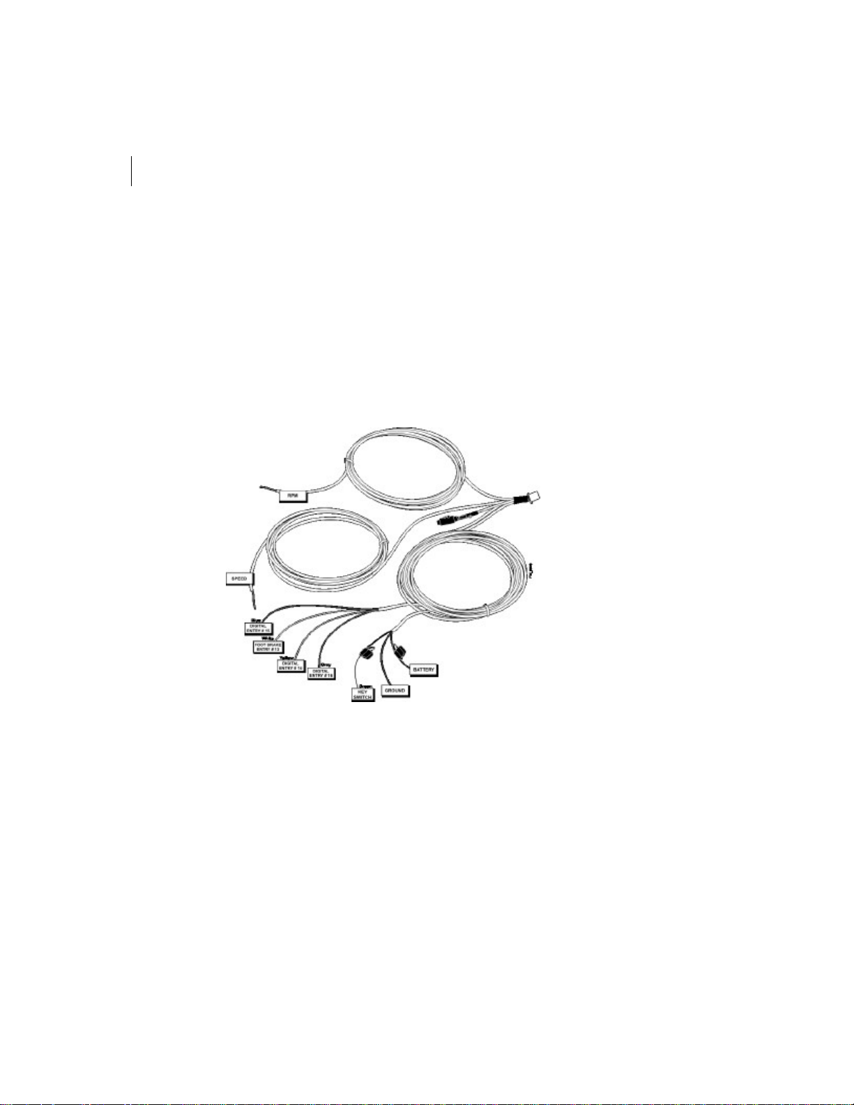
Installing the Copilot cable in pulse-measured vehicles, requires that you—
• Install the FF converters and connect them to the vehicle’s speed and RPM inputs
• Connect the key switch wire.
• Connect the battery wire to provide a power source for the Copilot.
Figure5 Connecting the Copilot Cable in Pulse-measured Vehicles
FM0026.eps
To install FF converters in pulse-measured vehicles:
1 Unscrew the fuse box under the dashboard on the driver’s side.
2 Lower the fuse box completely. This will allow you to insert the FF converters under
the dashboard.
3 Connect the red wires of both FF converters to the vehicle’s battery wire.
4 Connect the black wires of both FF converters to a ground within the vehicle.
5 Connect the white wire of the speed FF converter to the vehicle’s speed wire/input.
Page 68

FLEETLINK
31
Hardware Installation and Configuration Guide
6 Connect the orange wire of the speed FF converter to the speed wire of the Copilot
cable.
7 Connect the yellow wire of the RPM FF converter to the vehicle’s RPM wire.
Tip You can locate the RPM wire at the back of the RPM gage. The RPM wire and the
ground wire are twisted together at the back of the gage. Use a pulsemeter to determine
which wire is the RPM wire and which is the ground wire.
Note If the vehicle does not have an RPM gage, connect the yellow wire of the RPM FF
converter to the wire connected to the alternator.
Warning Never connect the Copilot cable directly to the RPM wire as this will prevent the
RPM gage from displaying the RPMs.
8 Connect the orange wire of the RPM FF converter to the RPM wire of the Copilot cable.
To connect the key switch wire in pulse-measured vehicles:
1 Locate the vehicle’s key switch wire. The key switch wire transmits the starter signal
(i.e., the On position).
2 Connect a multimeter to the key switch wire.
3 Turn the key switch to the Accessories position.
4 Verify that the multimeter reading is 0 VDC.
5 Turn the key switch to the On position.
6 Verify that the multimeter reading is 12 VDC or more.
7 Connect the vehicle’s key switch wire to the key switch wire of the Copilot cable.
8 Verify that the multimeter reading is 12 VDC or more. It is important that you are not
connected to the accessories circuit, so that you have a constant signal when starting.
Page 69

CHAPTER 3
32
Installation
To connect to the battery wire and the ground:
1 Locate the battery wire.
2 Connect the vehicle’s battery wire to the battery wire of the Copilot cable.
3 Connect the ground wire from the Copilot cable to a ground within the vehicle.
Page 70
FLEETLINK
Hardware Installation and Configuration Guide
Installing the Junction Box
When installing the junction box, consider the following:
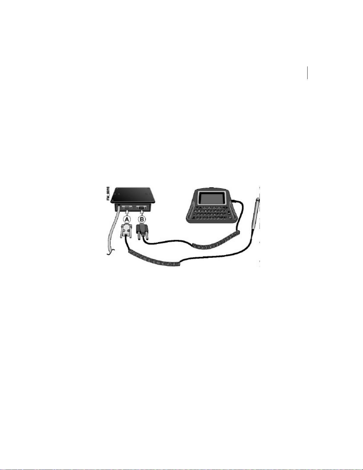
• Install the junction box so that it is easily accessible by the driver.
• Make sure there is enough space behind the junction box, so that you can connect
the driver display and bar code scanner.
• If you must drill a hole to install the junction box, make sure that nothing will be
damaged behind or beneath the surface.
Figure6 Installing the Junction Box
33
To install the junction box:
1 Select a location for the junction box.
2 Drill the holes for the junction box in the dashboard.
3 Pass the junction box cable through to the Copilot.
4 Plug the bar code scanner connector (A) into the designated connector at the back of
the junction box.
5 Plug the driver display connector (B) into the designated connector at the back of the
junction box.
6 Screw the junction box into the dashboard with the front panel facing the driver.
7 Connect the junction box cable to the Copilot following the procedure “Installing the
Copilot” on page34.
Page 71

CHAPTER 3
34
Installation
Installing the Copilot
Fleetmind recommends that you install the Copilot inside the dashboard. However, you
can also install the Copilot underneath the passenger seat or behind the middle console
(the doghouse). Be sure to install the Copilot with the connection plate facing outward, so
that you can easily access the connectors.
Caution While it is possible to install the Copilot under the passenger seat, it is not the
preferred location because of the increased risk of exposure to water or other liquids.
When installing the Copilot—
• Make sure the cables can connect to the Copilot without getting in the driver’s
way.
• Provide enough slack in the cables so they will not pull on the Copilot when
connected and risk pulling it out of place.
• Do not put it in a place where it will be exposed to direct sunlight, intense heat
(e.g., heat ducts) or liquid.
• Do not install it near a magnetic field (e.g., welding machine).
• Fasten it securely into place in the dashboard or underneath the passenger seat.
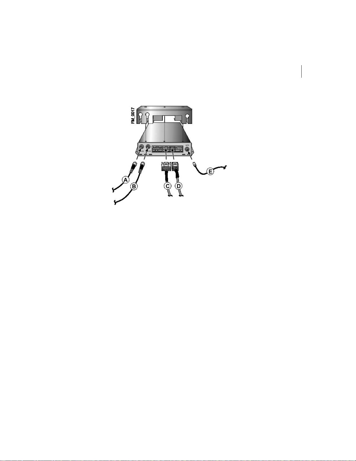
Figure7 shows the Copilot and the cables that connect to it.
Page 72
FLEETLINK
35
Hardware Installation and Configuration Guide
Figure7 Installing the Copilot
To install the Copilot inside the dashboard or behind the middle console:
1 Remove the dashboard fastening panels.
2 Remove the Copilot’s faceplate.
3 Pass the junction box cable through the dashboard to the Copilot.
4 Plug the 17-pin junction box connector (D) into the designated connector of the
Copilot.
5 Plug the 24-pin connector of the ECM cable (C) into the designated connector of the
Copilot.
6 Pass the antenna cables through the dashboard to the Copilot.
7 Connect the antenna cables to the connectors of the Copilot as follows:
• Plug the LAN antenna cable (A) into the WLAN RF connector.
• Plug the GPS antenna cable (E) into the GPS RF connector.
• Plug the WAN antenna cable (B) into the WWAN RF connector (optional).
8 Plug the satellite antenna cable into the Quad 2 Com port connector of the ECM cable
(optional).
Page 73

CHAPTER 3
36
Installation
Note Fleetlink does not support the installation of a WAN antenna and a satellite antenna
at the same time.
9 Fold back and attach the surplus cables with a tie-wrap and put them under the
dashboard.
10 Once you have installed and tested all the Fleetlink components, put the faceplate
back on the Copilot and screw it into place in the dashboard.
Note FleetMind recommends that you wait until you complete the configuration
procedure before you replace the dashboard fastening panels.
Page 74

FLEETLINK
37
Hardware Installation and Configuration Guide
To install the Copilot under the passenger seat:
1 Remove the Copilot’s faceplate.
2 Remove the cab floor mat fastening panels and any accessories that prevent the cables
from passing under the mat between the floor structures.
3 Pass the junction box cable to the Copilot.
4 Plug the 17-pin junction box connector (D) into the designated connector of the
Copilot.
5 Plug the 24-pin connector of the ECM cable (C) into the designated connector of the
Copilot.
6 Pass the antenna cables to the Copilot.
7 Connect the antenna cables to the connectors of the Copilot as follows:
• Plug the LAN antenna cable (A) into the WLAN RF connector.
• Plug the GPS antenna cable (E) into the GPS RF connector.
• Plug the WAN antenna cable (B) into the WWAN RF connector (optional).
8 Plug the satellite antenna cable into the Quad 2 Com port connector of the ECM cable
(optional).
Note Fleetlink does not support the installation of a WAN antenna and a satellite antenna
at the same time.
9 Fold back and attach the surplus cables with a tie-wrap and put them under the mat
between the cab floor structures.
10 Once you have installed and tested all the Fleetlink components, put the faceplate
back on the Copilot and screw it into place under the passenger seat.
Page 75
CHAPTER 3
38
Installation
Installing the Driver Display
When installing the driver display, consider the following:
• Install the driver display so that it can be viewed easily and reached by the driver
when seated.
• Select an appropriate and safe location to install the driver display. Make sure
that you chose a location where you can fix the support solidly into the dash so
that it can bear the weight of the driver display.
• Prior to drilling a hole to install the driver display support, make sure that
nothing will be damaged behind or beneath the surface.
• Install the support above the junction box at a distance that allows you to connect
the driver display easily to the junction box.
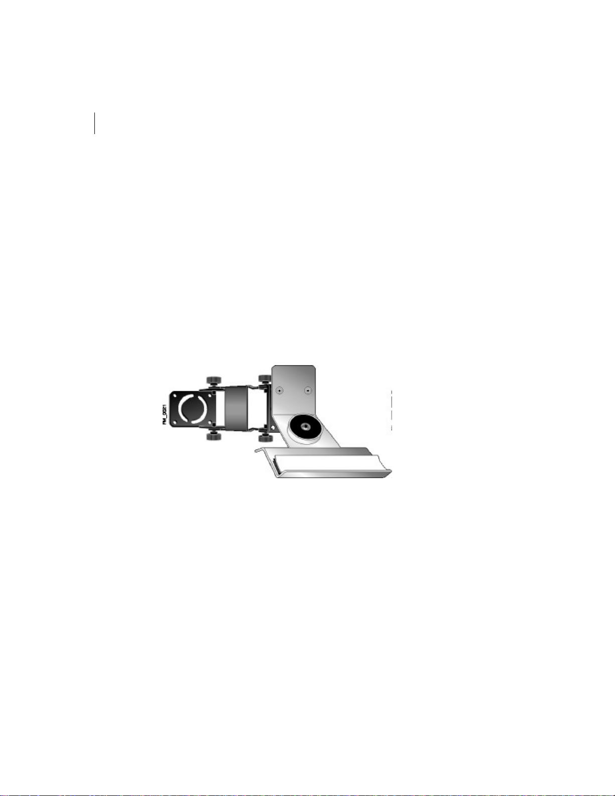
Figure8 Installing the Driver Display
Page 76

FLEETLINK
39
Hardware Installation and Configuration Guide
To install the driver display:
1 Select a location for the driver display.
2 Loosen the bolts of the support and unfold it.
3 Using the support as a guide, drill holes into the dashboard at the desired location.
4 Screw the driver display support to the dashboard.
5 Remove the velcro strip from the driver display support.
6 Remove backing and stick the velcro strip to the bottom of the driver display.
7 Install the driver display on its support. Make sure that it is secured in place by the
velcro and the magnet.
8 Adjust the angle of the driver display so that the screen faces the driver and tighten the
bolts of the support.
9 Plug the driver display’s DB-9 male connector into the designated connector at the
back of the junction box (see Figure8on page38).
Page 77

CHAPTER 3
40
Installation
Installing the Bar Code Scanner
When installing the bar code scanner, consider the following:
• Install the bar code scanner so that it can be reached easily by the driver when
seated.
• Select an appropriate and safe location to install the driver display. Make sure
that you chose a location where you can fix the support solidly into the dash so
that it can bear the weight of the driver display.
• Prior to drilling a hole to install the support, make sure that nothing will be
damaged behind or beneath the surface.
• Make sure that the bar code scanner can be connected easily to the junction box.
To install the bar code scanner:
1 Select a location for the bar code scanner.
2 Loosen the bolts of the support and unfold it.
3 Using the bar code scanner support as a guide, drill holes into the dashboard at the
desired location.
4 Screw the support to the dashboard.
5 Adjust the angle of the support and tighten the bolts.
6 Insert the bar code scanner in its support.
7 Plug the bar code reader connector into the designated connector at the back of the
junction box (see Figure6on page33).
Page 78

Chapter 4
Configuration
Page 79

CHAPTER 4
42
Configuration
Introduction
Once the Fleetlink components are installed, you must configure the on-board
computer or Copilot using an installation terminal. Among other things, configuring
the Copilot ensures that communication will function properly and that the
Fleetlink management software will properly recognize the Copilot and its
associated vehicle. In this chapter, you will learn how to configure the Copilot, as
well as how to perform verification tests.
Preparation
Before you start to configure the Copilot, make sure that the vehicle is within the
RFcoverage of the company’s terminal. To prepare the vehicle for the configuration
procedure—
• Apply the parking brakes.
• Put the vehicle in neutral.
• Stop the Engine.
• Turn the key switch to On.
At any time during configuration of the Copilot, you may—
• Press F1 to return to the main menu.
• Press Enter to select a menu.
Page 80
FLEETLINK
Hardware Installation and Configuration Guide
Configuring the Copilot
To configure the Copilot in the vehicle:
1 Plug the jack of the installation terminal into the cigarette lighter.
2 Connect the installation terminal to the junction box. Use the J45–DB9 adapter, if
necessary.
3 Press F1 to display the main menu.
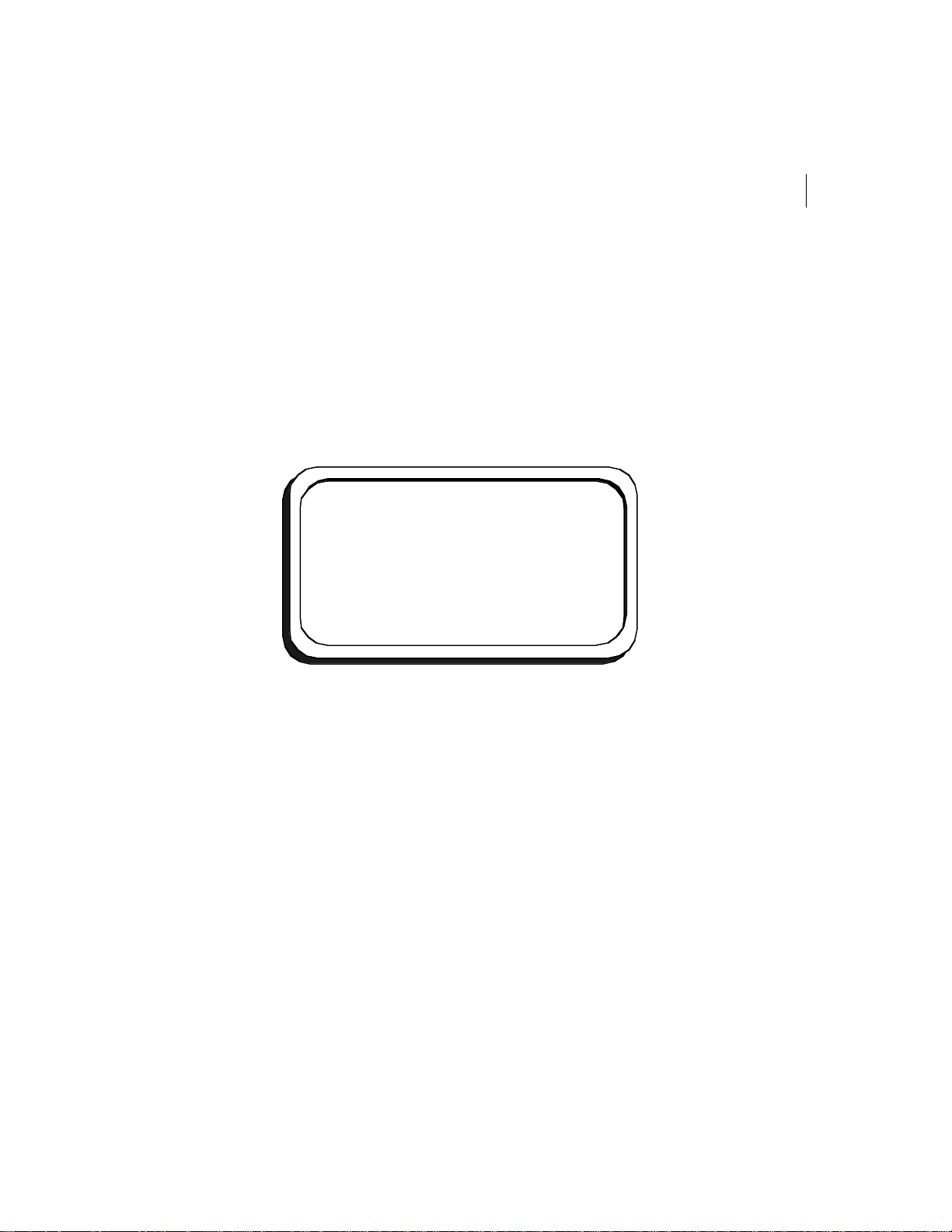
Figure9 Main Menu on the Installation Terminal
43
-----------------------------------
-----------------------------------
sys
com <sub menu>
app <sub menu>
data <sub menu>
> sys
MAIN MENU
<sub menu>
4 At the prompt, type sys and press Enter.
The options available in system (sys) mode appear on the installation terminal. Use the
arrow keys of the keyboard to scroll through the list.
Page 81
CHAPTER 4
44
Configuration
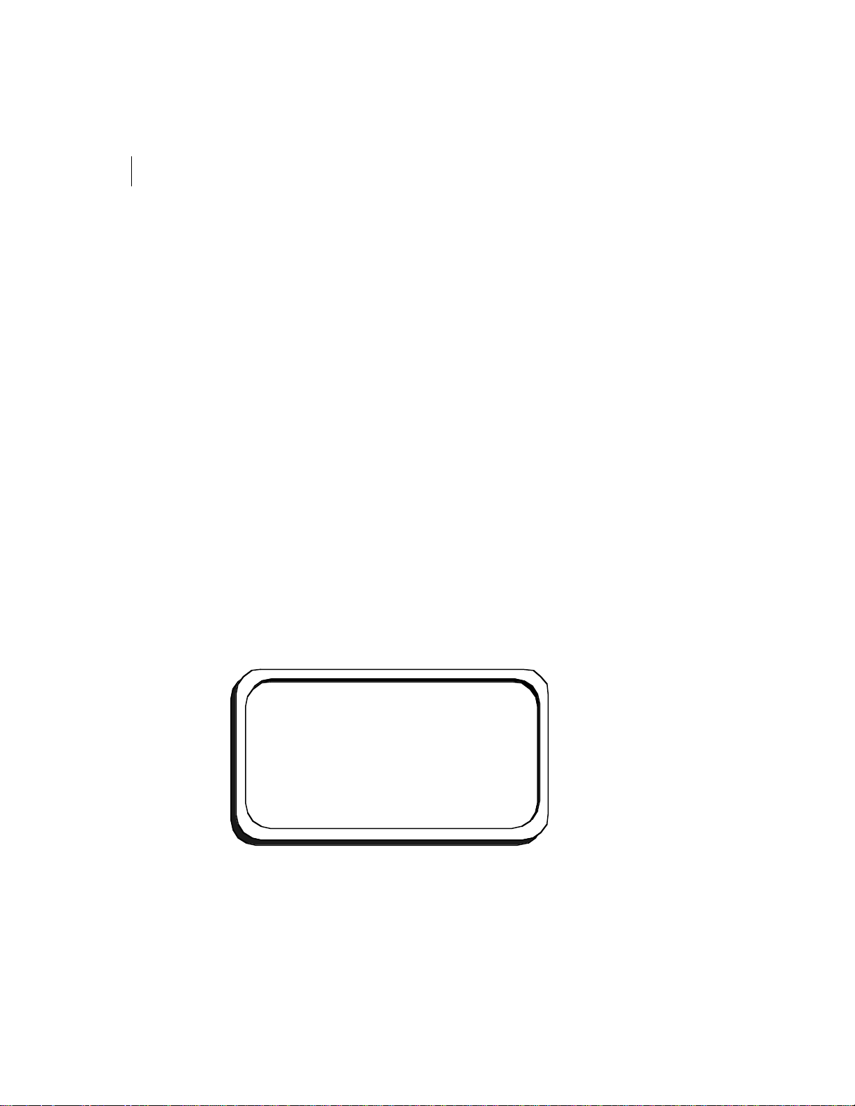
Figure10 Options of the SYS Command
-----------------------------------
----------------------------------rtc modification de la RTC Hardware
log Log des evenements
startup Startup subsystem
fs File System
cfg Configuration
arrettmp Arret Temp
cerr Conservation des Erreurs
install Installation module
ressource View of synchronization resources
task View all task in system
cpu View CPU usage
dump shows memory content
buffer shows MQX buffer allocation
core General Info
imp 68302
SYS
5 At the prompt, type install and press Enter.
6 At the prompt, type reset and press Enter. You may now proceed with the
configuration.
Figure11 Resetting the Copilot
General Information
Cie Id : 111
Unit Id : 2222
step : 5.Installation complete
COMMAND
reset Reset the copilot, and set like a new one
report View the Report’s results
> reset
7 At the prompt company identification number, specify the company identification
number assigned by FleetMind and press Enter.
Page 82

FLEETLINK
45
Hardware Installation and Configuration Guide
8 At the prompt copilot identification number, specify the identification number of the
Copilot installed on the vehicle and press Enter.
Note The Copilot identification number must match the Copilot number entered for the
vehicle in the control center.
9 At the prompt Frequency, specify the company frequency number assigned by
FleetMind and press Enter.
10 At the prompt Manager’s ID, specify the identification number of the control center
and press Enter. To keep the default value, do not specify a value and press Enter.
Caution Do not enter 0 (zero) as the value. Entering 0 will disable the short-range RF
connection and you will not be able to continue with the configuration process.
11 At the prompt Manager’s Mobitex address, specify the cellular address. If there is no
cellular antenna installed, press Enter to keep the default value.
12 At the prompt Manager’s iDEN address, specify the iDEN address and the port
number. If there is no iDEN antenna installed, press Enter to keep the default value.
13 At the prompt Manager’s Msat appSel, specify the satellite communication address.
If there is no satellite antenna installed, press Enter to keep the default value.
The configuration procedure starts configuring the communications systems. When
the configuration is completed, the following screen appears:
Page 83
CHAPTER 4
46
Configuration
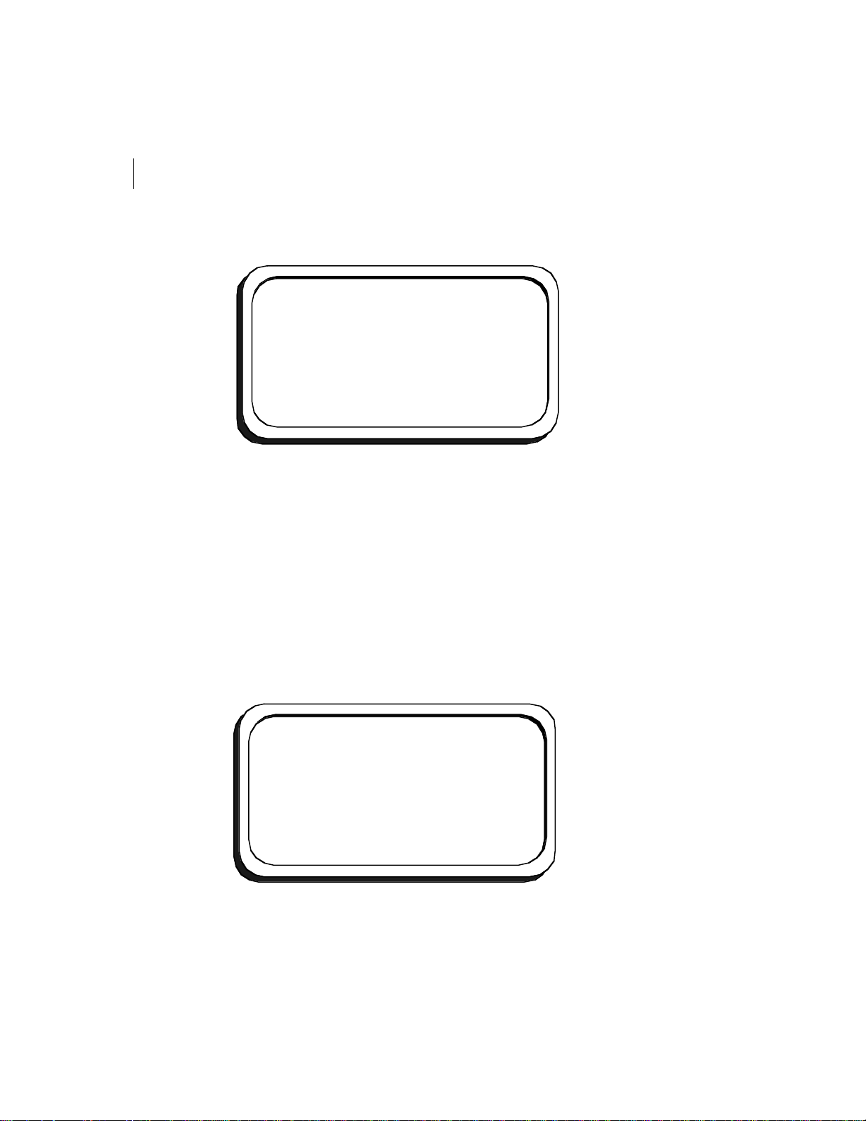
Figure12 Completing the Copilot Configuration
Configuration download completed
Current date is: 2002-11-29
Enter current date [YYYY-MM-DD] :
Current time is: 14:06:41
Enter Current time (24h format) [HH:MM:SS] :
Verifying RTC time and date
Resetting...
14 Specify the date and press Enter. If the values shown are correct, press Enter to
confirm them.
15 Specify the time and press Enter. If the values shown are correct, press Enter to
confirm them.
The database should be detected within 30 seconds. Once it is detected, continue with
the configuration procedure.
If the database is not detected, press F1 or Ctrl-Break to return to the main menu.
Verify that the all the Fleetlink components are properly connected and start the
configuration procedure from the beginning.
16 In the vehicle, turn the key switch to Off.
Figure13 Executing the Key Switch Test
KEY SWITCH TEST [ENTER=Skip]
Please turn off the key switch
<Waiting key switch>
Please turn on the key switch
<Waiting key switch>
Test completed
Page 84

FLEETLINK
47
Hardware Installation and Configuration Guide
17 On the installation terminal, wait for the prompt Please turn on the key switch and
turn the key switch to On.
The installation terminal verifies the communication with the electronic control
module (ECM).
18 At the prompt Enter odometer value, specify the vehicle’s odometer value and press
Enter. Do not include the decimal value when entering the odometer value.
Note Fleetlink does not support the use of commas, periods or spaces.
19 Execute the tests for the digital entries following the instructions that appear on the
installation terminal. The number of tests that you must execute depends on the
number of digital entries connected to the vehicle and the Copilot.
When you have completed the digital entry tests, the Copilot transmits the installation
report to Fleetlink’s Victor Manager, Master Server within the terminal. The configuration
is complete when the entire report has been downloaded.
You can now perform verification tests to make sure that the data collected by the Copilot
is correct:
• “Verifying the Vehicle’s RPMs” on page48
• “Verifying the GPS Status Reading” on page49
Page 85

CHAPTER 4
-----------------------------------
48
Configuration
Verifying the Vehicle’s RPMs
After completing the configuration, you should perform tests to measure the vehicle’s
RPMs to make sure that the data collected by the Copilot is correct.
To verify RPM data:
1 In the vehicle, turn the key switch to On and start the engine.
2 On the installation terminal keyboard, press F1 to access the main menu.
3 At the prompt, type data to select the data submenu.
4 At the prompt, type uccd and press Enter. The following information appears on the
installation terminal.
Figure14 Display in UCCD Mode
----------------------------------showt Show or not invalid data
Nb Entry/Total Entry : 19/64
Data Size/Data Size Max. : 48/512
Key switch 1
Speed 0
Odometer (.1KM) 1000
Panic button 3
Voltage de JBox 2
UDAC int. temp. 29
RF RSSI 68
Foot brake 1
Gen contact 1 0
Gen contact 2 1
Gen contact 3 0
RPM 0
Odometer 1000
UCCD
5 Increase the engine RPM and press Shift-? on the installation terminal keyboard to
obtain the RPM level.
6 Repeat the test at different RPMs to verify that the RPM values and the values
displayed on the driver display are the same.
Page 86

FLEETLINK
49
Hardware Installation and Configuration Guide
Verifying the GPS Status Reading
You can view the vehicle’s GPS status on the installation terminal. To obtain the GPS
reading, the vehicle must be outdoors. If the vehicle is inside a garage, the antenna will not
receive the GPS signal and you will not get a reading. Exit the garage and allow a few
minutes to obtain a satellite connection.
To verify the GPS reading:
1 Press F1 to display the main menu.
2 At the prompt, type data to access the data submenu.
3 At the prompt, type gps and press Enter.
4 The following information appears on the installation terminal screen. Use the arrow
keys to scroll through the screen.
Figure15 Verifying GPS Data
Lassen SKI II Statistics:
Lassen SK II device is present
Firmware version Major: 8, Minor: 6
Receiver Status: Doing position
Fixes BBRAM was not available at startup
Number of satellites in view: 7
3D Fixes, Automatic,
Differential DGPS
Latitude: 40.31’16:N
Longitude: 73o42’38”W
5 Wait 15 minutes to obtain a GPS position reading.
6 At the prompt, type gps and press Enter.
7 Verify your GPS data.
Page 87

50
NOTES
Page 88

Appendix 1
Specifications
Page 89
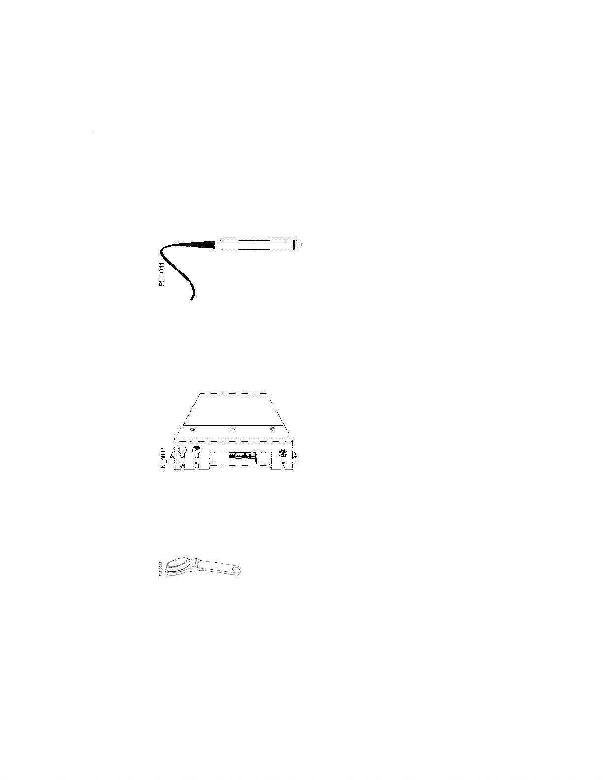
APPENDIX 1
52
Specifications
Fleetlink Component Specifications
Bar Code Scanner and Support
(not shown)
Copilot
Bar Code Scanner—
Operating Temperature : -4ºF to +122ºF
(-20ºC to +50ºC)
Relative Humidity : 95% max non-condensing
Input Voltage: 4.5 V to 5.5 V
Typical Internal Consumption: 19 mA
Weight : 3.6 oz. (102 g)
Length : 7.5 in. (19.1 cm)
Diameter: 0.5 in. (1.3 cm)
Scanning Speed : 1.9-50 in./sec. (5-127 cm/sec.)
Tip: replaceable sapphire
Cable Length : 5.9 ft. (1.8 m)
Bar Code Scanner Support —
Dimensions (H x W x D): 3.74 x 1.97 x 2.17 in.
(9.5 x 5 x 5.5 cm)
Com Ports:
1 SAE J1708-J1587,
3 RS232
RAM Memory : 2 MB
Flash Memory: 4 MB
Antenna Connectors :
WLAN connector
GPS connector
WWAN connector (optional)
Operating Temperature : -13ºF to +122ºF (-
25ºCto+50ºC)
Relative humidity: 0% to 95% (non-condensing)
Supply Inputs: 16 digital inputs, including 8
supplying voltage
Dimensions (H x W x D): 8.8 x 7.8 x 1.8 in.
(22.5x20 x 4.7 cm)
Dallas Key
1D and 256-bit EEPROM
Page 90
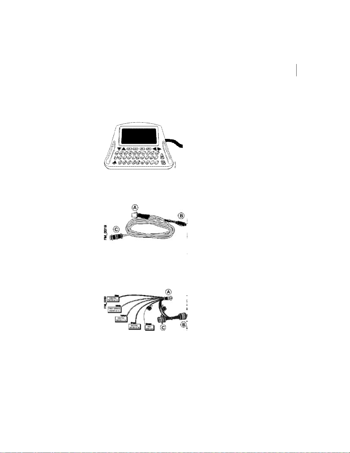
FLEETLINK
Hardware Installation and Configuration Guide
53
Driver Display and Support
(not shown)
ECM Connector Cable
Driver Display—
Display: VFD with four luminosity levels
Keyboard : QWERTY
Screen (H x W): 8 lines x 21 characters
Dimensions (H x W): 5.75 x 7.25 in. (14.5 x 18.5 cm)
Connector: serial interface
Support—
Dimensions (folded) (W x H x D): 4.5 x 3.5 x 5 in.
(11.5 x 9 x 12.7 cm)
Cable Type : J1708
Length : 16.4 ft. (5 m)
Connectors:
A—24-pin Copilot connector
B—Satellite connector (Quad 2 Com port)
C—ECM connector
ECM Deutsch Connector Harness
Connector: Copilot connector (A), 6 pin or 9 pin
Jacks:
B—jack remains free (to connect to diagnostic
tool connector)
C—ECM jack
Fuses: Two 5A fuses (Type ATC 5)
Input wires:
1 key switch input wire (green)
1 brake signal input wire (white)
3 digital input wires (blue, yellow and grey)
Page 91
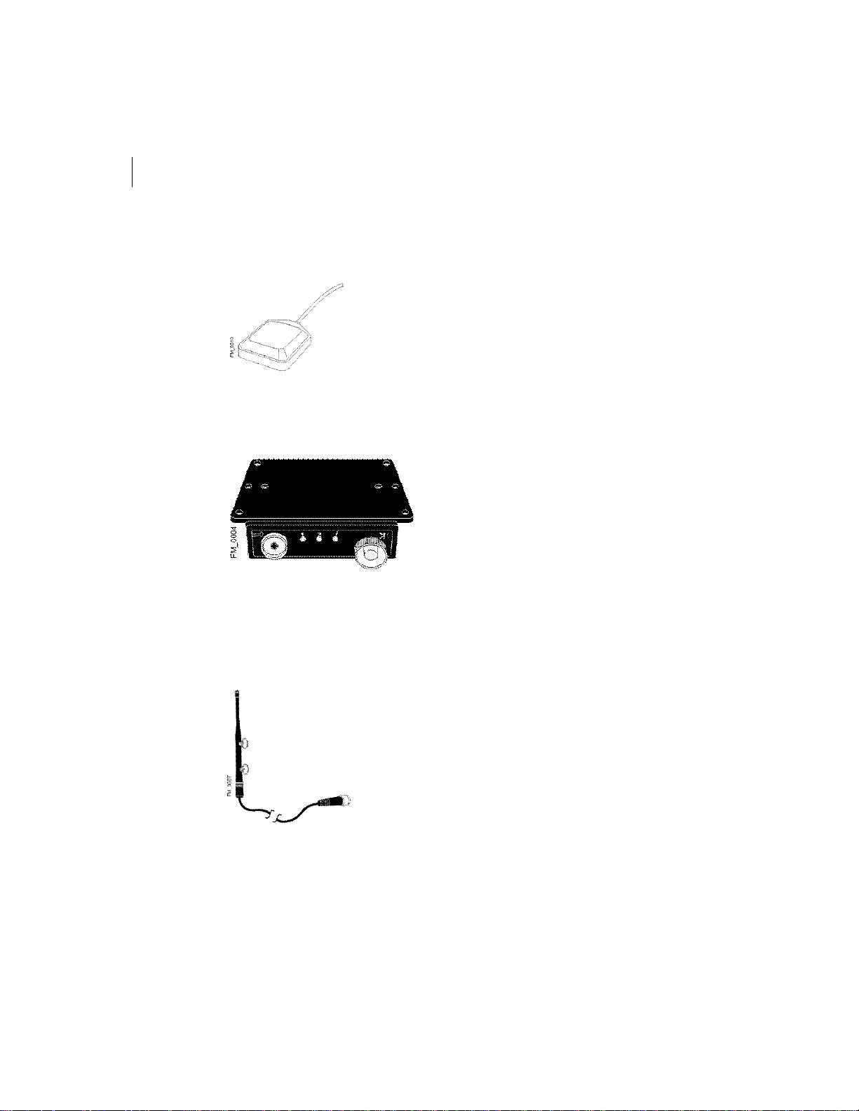
APPENDIX 1
54
Specifications
GPS Antenna
Junction Box
Fastening: magnetic
Tensile strength: 29.4 N/mm
Frequency: 1 575.42 ± 1.023 MHz
Gain: ± 27 dBi
Dimensions: 1.65 x 1.99 x 0.54 in.
(42x50.5x13.9mm)
Length of connecting cable: 16.4 ft. (5 m)
COM ports: 2
Bar code scanner port
Driver display port
Connector cable: 16.4 ft. (5 m)
Computer connector: 17-pin Copilot connector
LEDs:
Red—indicates driver connection (dimmed)
Yellow—indicates connection with the base
Green—indicates Copilot, driver display and
junction box are on
Other:
Dallas key reader (with red or green LED,
depending on model)
Panic button
Dimensions (W x H x D): 5.5 x 2.95 x 1.4 in.
(14x7.5 x 3.6 cm)
2
LAN Antenna
Transmission range: ± 600 m
Frequency: 902 to 928 MHz
Gain: 3 dBd
Fastening: suction-cup
Connector: TNC
Page 92
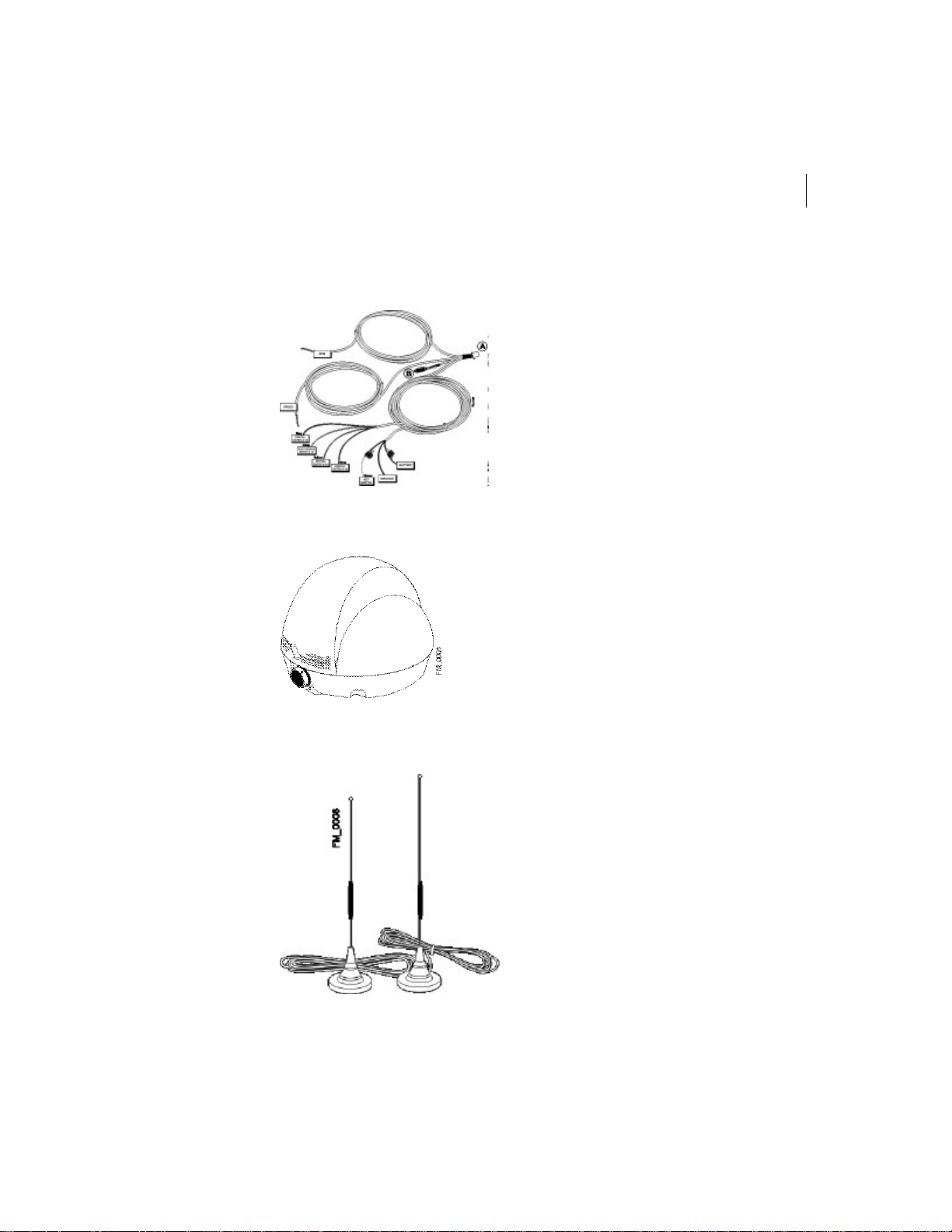
FLEETLINK
Hardware Installation and Configuration Guide
55
Pulse Cable
Satellite Radio Antenna
Length : 16.4 ft. (5 m)
Connectors:
A—24 pin Copilot connector
B—Satellite connector (Quad 2 Com port)
Fuses: Two 5A fuses (Type ATC 5)
Input wires.
1 key switch input wire (green)
1 brake signal input wire (white)
3 digital input wires (blue, yellow and grey)
2 pulse input wires (white with label RPM
and SPEED)
2 wires for power (label with Battery 24 Volt
Max and Ground)
Radio—
Operating Temperature : -40ºF to +122ºF
(-40ºC to +50ºC)
Relative Humidity Tolerance: 98%
Input Voltage: 9 VDC - 16 VDC
Internal Consumption :
250 mA receiving mode
3.3A transmitting mode
Antenna —
Fastening: 3 screws, ¼-20
Frequency: L-Band, 1.525 GHz to 1.660 GHz
WAN Antenna
Fastening: magnetic
Tensile Strength: 29.4 N/mm
Transmission Range:
896 to 941 MHz (Mobitex)
806 to 866 MHz (iDEN)
2
Page 93

56
NOTES
Page 94

Appendix 2
In-Vehicle Installation
Page 95
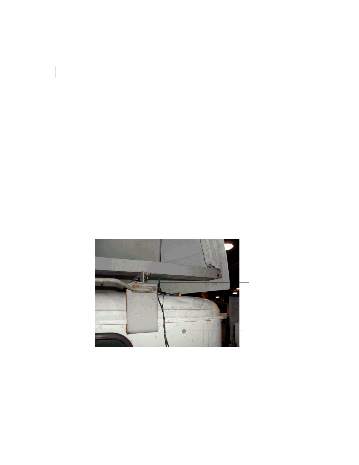
APPENDIX 2
58
In-Vehicle Installation
Introduction
This appendix shows a sample installation of the Fleetlink components in a truck. The
truck type used is an International, 4000-series model.
Installing the Antennas
The following pictures shows the installation of the GPS, LAN and WAN antennas and
how their cables are run through the cab.
Figure16 shows—
• Installation of a WAN (Mobitex) and GPS antennas.
• Placement of the hole for the antenna cables
• Use of tie-wraps to keep the installation orderly.
Figure16 Installing the WAN and GPS Antennas
Mobitex WAN Antenna
GPS Antenna
3/4” Hole for Antenna Cables
Page 96
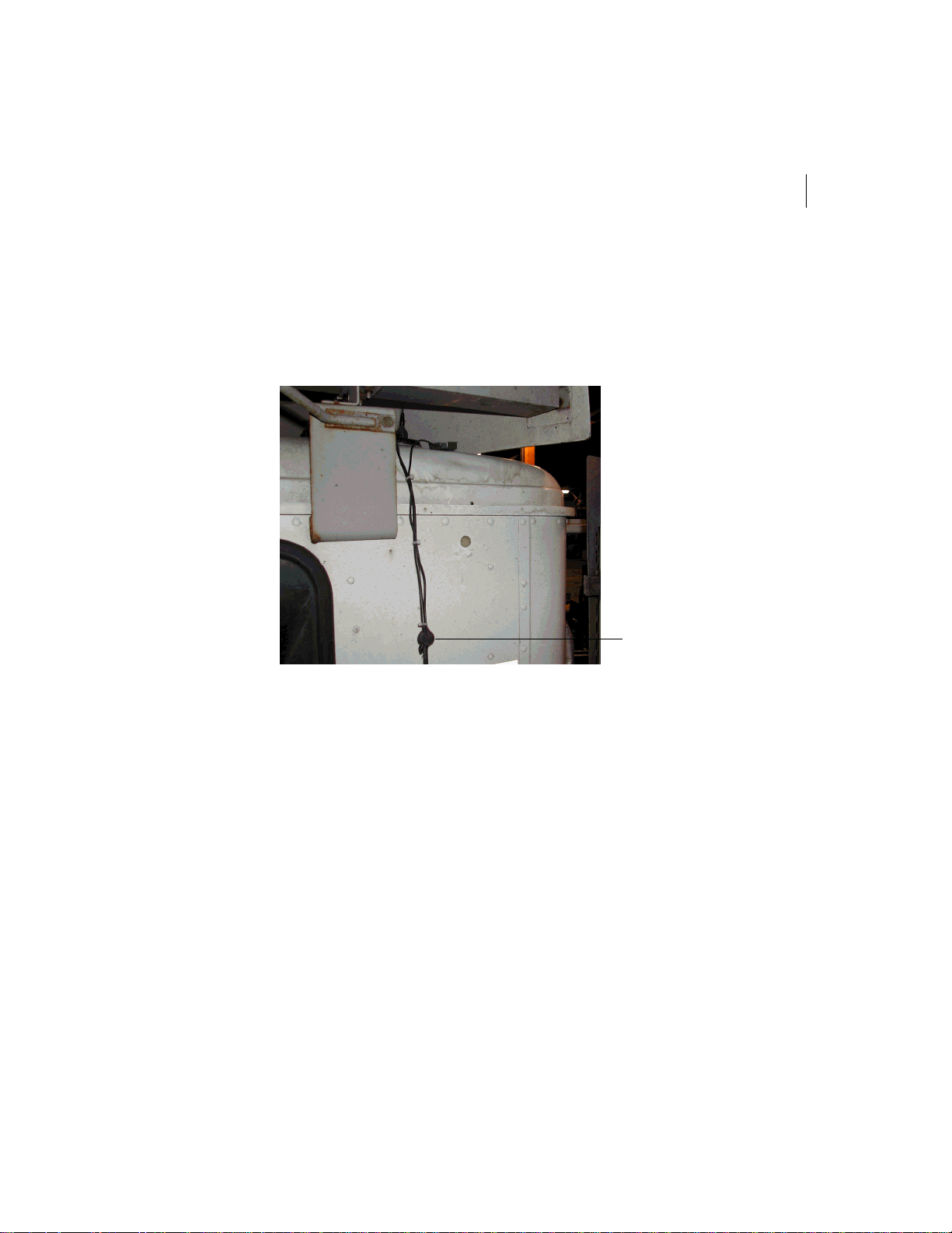
FLEETLINK
Hardware Installation and Configuration Guide
Figure17 shows—
• Placement of the seal on the antenna cable. You do not put the seal in place in the
hole until you have run the antenna cables through the hole, around the cab and
connected them to the Copilot.
Figure17 Installation of the Seal on the Antenna Cables
59
Grommet
Page 97
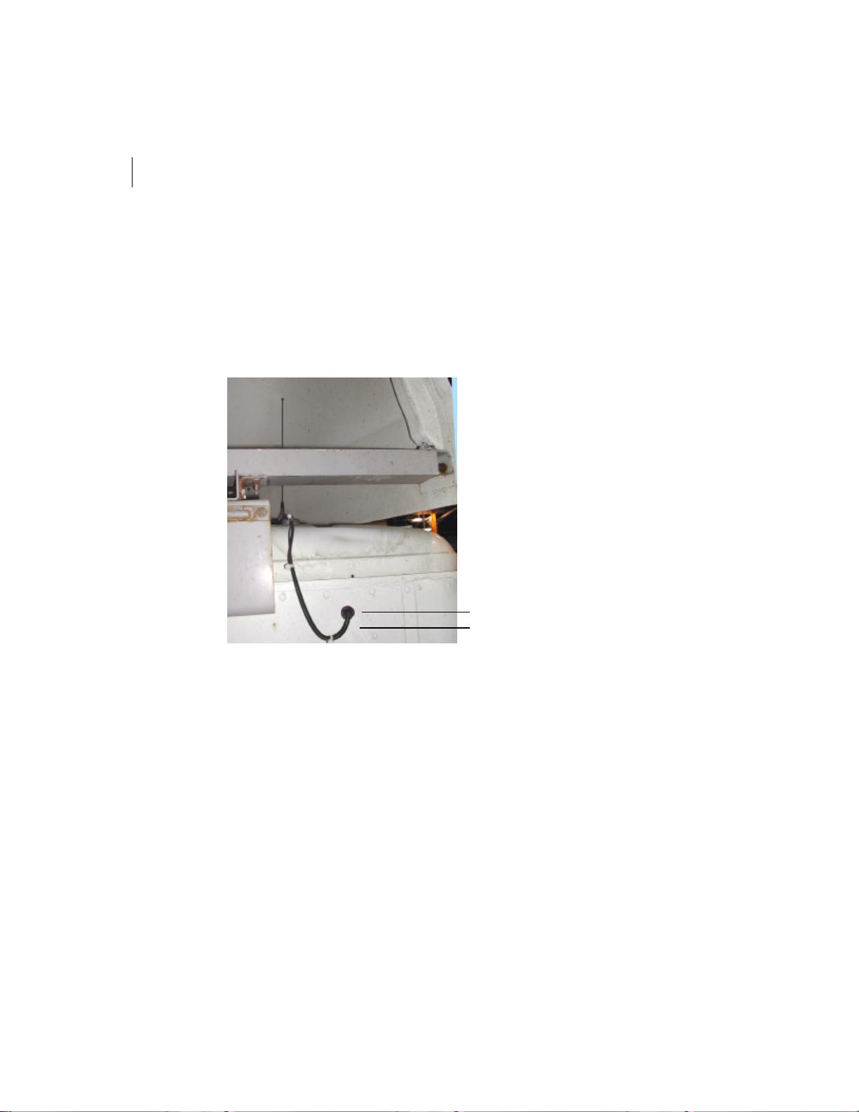
APPENDIX 2
60
In-Vehicle Installation
Figure18 shows—
• Installation of the antennas with the antenna cables passed through the hole.
• How the hole is closed using the seal and calking.
• Use of a drip loop on the antenna cable helps water run off the cables, thus
preventing water from running to the hole.
Figure18 Antenna Cables Passed Through the Hole with the Seal in Place
Seal and Calking in Place
Drip Loop
Page 98
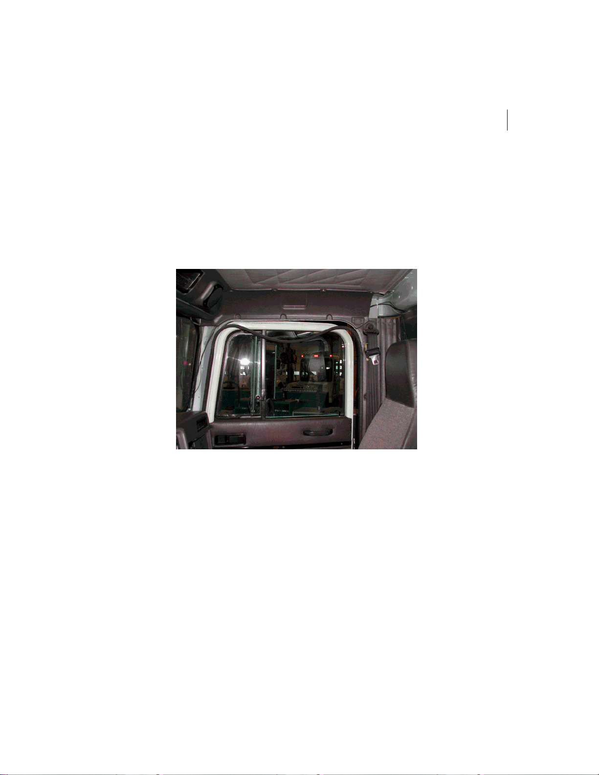
FLEETLINK
Hardware Installation and Configuration Guide
Figure19 shows—
• How the antenna cable are run from the hole in the back wall of the cab, over the
passenger door and down the right-side of the front window.
• Paneling and the weather stripping on the door have been removed to run the
cables. Once the cables are in place and connected to the Copilot, the paneling
and the weather stripping is put back in place.
Figure19 Running of GPS and WAN Antenna Cables Through the Cab
61
Page 99
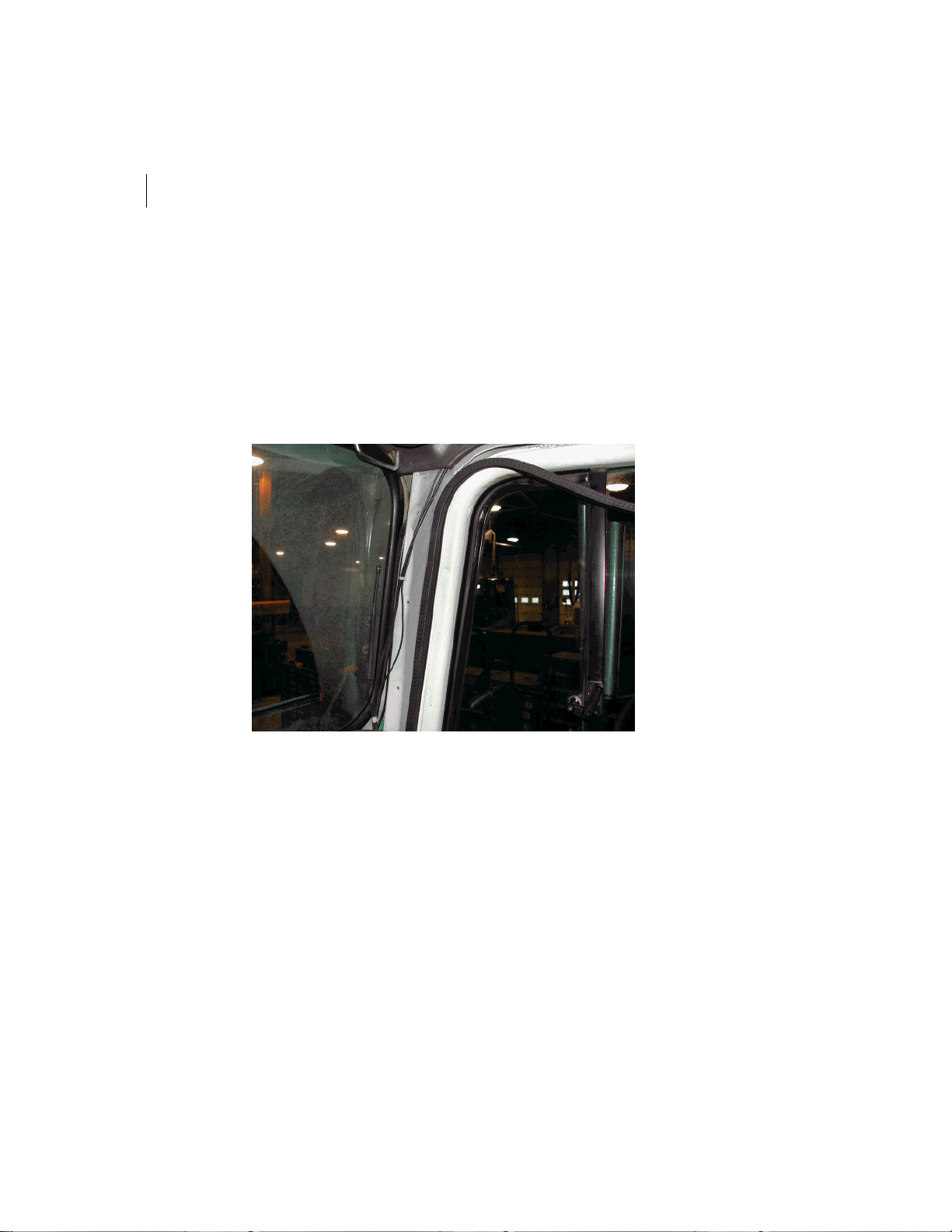
APPENDIX 2
62
In-Vehicle Installation
Figure20 shows—
• How to run the antenna cables above the passenger door. The paneling and
weather stripping have been removed and the antenna cables are attached with
tie-wraps are regular intervals.
• Installation of the LAN antenna in the lower-right corner of the front window.
The cable from the GPS, LAN and WAN antennas will now be run through the
dashboard to the Copilot.
Figure20 Running of Antenna Cables Above Passenger Door Down to Dashboard
Page 100
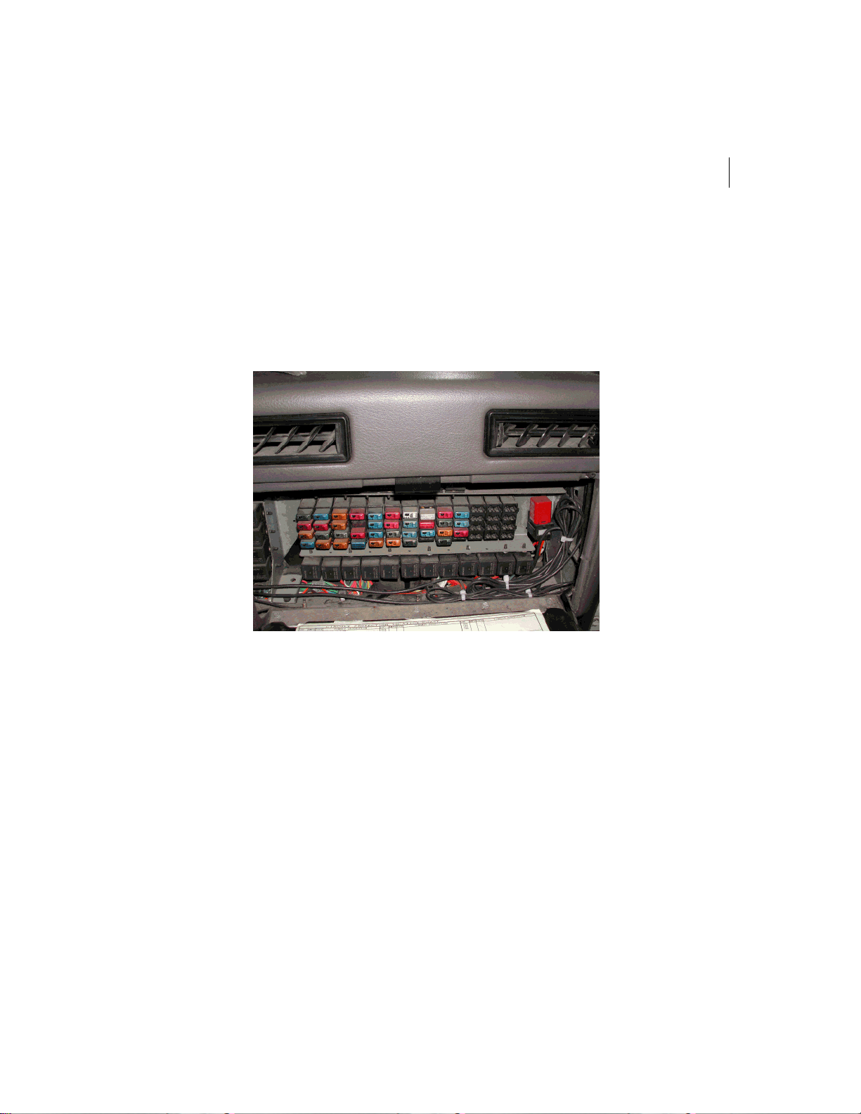
FLEETLINK
63
Hardware Installation and Configuration Guide
Figure21 shows—
• How the antenna cables for the GPS, LAN and WAN cables are run through the
dashboard, behind the glove compartment and in front of the fuse box.
• Once the cables are run through to the Copilot, any excess cable is tied up with
tie-wraps. The excess tie-wrap is then cut.
Figure21 Antenna Cables Behind the Glove Compartment and in Front of the Fuse Box
 Loading...