

Page 1

Fleetlink
Access Point 300
Installation Guide
Page 2

© 2003-2005 FleetMind Solutions Inc. All rights reserved.
Fleetlink Access Point 300 Installation Guide
The information contained in this manual is subject to change without notice. All statements, information and
recommendations in this manual are believed to be accurate, but are presented without warranty of any kind,
express or implied. Users must take full responsibility for their use of any products.
No part of this publication may be reproduced or transmitted in any form or by any means, electronic or mechanical,
including photocopying and recording without prior written consent from FleetMind Solutions Inc.
The FleetMind and Fleetlink logos and designs are trademarks of FleetMind Solutions Inc. All other trademarks are
the property of their respective owners.
The license agreement is contained within the software’s installer.
FleetMind Solutions Inc., 455 Fénelon Blvd., Suite 110, Dorval QC H9S 5T8, CANADA
Document Part Number: 33-911-0004-01.B (0506)
Page 3

Preliminaries Chapter 1
Welcome to Fleetlink ............................................................... 6
Important Safety and Compliance Information ........................ 6
FCC Compliance Statement (USA)...................................... 7
Industry Canada Certification ............................................... 7
Approved antennas list......................................................... 7
Safety.................................................................................... 8
Using the Documentation........................................................ 9
Conventions.......................................................................... 9
Suggested Reading............................................................ 10
Service and Support.............................................................. 10
Contacting Us........................................................................ 10
Introduction Chapter 2
Introduction............................................................................ 14
What is the Access Point 300?.............................................. 14
Access Point 300 Radio Box.............................................. 15
Proxim RXA-300................................................................. 16
ESCC Card......................................................................... 16
Software.............................................................................. 17
Cable and Splitter............................................................... 18
Access Point Installation Terminal...................................... 19
Manager Short-Range RF Access Point Properties........... 21
CONTENTS 3
Installation Chapter 3
Introduction............................................................................ 24
Installation Considerations .................................................... 24
Prior To Installation............................................................. 24
Antenna Installation............................................................ 25
Installing the Access Point 300.............................................. 30
Access Point 300 System Components.............................. 30
Installation Procedure......................................................... 32
Page 4

CONTENTS4
Page 5

Chapter 1
Preliminaries
Page 6

CHAPTER 1
6
Preliminaries
Welcome to Fleetlink
Welcome to Fleetlink, FleetMind’s fleet management solution. In this installation
guide, you will learn about the Fleetlink Access Point 300, including how to install
it. The guide is divided into three chapters (see “ Using the Documentation” in this
chapter), which will help you understand how the Access Point 300 works and the
role it plays in the Fleetlink solution.
Important Safety and Compliance
Information
Note This section applies to the Fleetlink Access Point 300 model, specifically model S-AP-
300.
Before you install or use the Fleetlink product, read the FCC and other regulatory material
found below, as well as in the other documents that accompanied your order.
This section provides information on the following topics:
• FCC compliance statement (USA)
• Industry Canada Certification
• Approved antennas list
• Safety
Warning To meet FCC/IC RF exposure guidelines, you must keep at least 8in. (20 cm.)
from the antenna during operation.
Page 7

FLEETLINK ACCESS POINT 300
7
Installation Guide
FCC Compliance Statement (USA)
This equipment has been tested and found to comply with the limits for a Class B digital
device, pursuant to Part 15. These limits are designed to provide reasonable protection
against harmful interference in a residential environment notwithstanding use in
commercial, business and industrial environments. This equipment generates, uses, and
can radiate radio frequency energy and, if not installed and used in accordance with the
product manuals, may cause harmful interference to radio communications. This
equipment also complies with the FCC Part 15 Subpart C.
Caution Changes or modifications to this unit not expressly approved by the party
responsible for compliance could void your authority to operate this equipment.
Industry Canada Certification
This Class B digital apparatus complies with Canadian ICES-003 and RSS 210.
Approved antennas list
Table1 Approved antennas
Item Part Number Type Gain
1 891-001
Discontinued
2 891-003 +
891-004
3 891-023 Ground plane omni antenna “connector N” 2.10 dBi
4 891-026 Inside glass mount blade antenna “connector TNC” 3.20 dBi
1/2 wave coaxial dipole antenna “connector TNC” 4.14 dBi
Whip antenna with magmount base and 15 feet
coax cable “connector TNC”
4.64 dBi
Page 8

CHAPTER 1
8
Preliminaries
Safety
Antenna installations should only be performed by trained personnel.
Observe electrical shock hazard precautions. Keep antenna and mast clear of all power
transmission lines. Do not secure antenna mast to any structure unless the antenna mast is
electrically bonded to a good ground for lightening protection.
Note It is the responsibility of the installer to observe all applicable local, provincial, and
federal regulations.
Page 9

FLEETLINK ACCESS POINT 300
Installation Guide
Using the Documentation
This installation guide assumes some basic understanding of the Fleetlink fleet
management system and is intended for installers. It is divided into the following three
chapters:
1 Preliminaries
Provides general information about the manual, safety and compliance information,
as well as information on how to contact customer support.
2 Introduction
Provides an overview of the Access Point 300, including information about its
components.
3 Installation
Provides installation considerations, as well as detailed installation instructions.
Conventions
9
This user guide uses the following conventions to convey instructions and information:
Table2 Installation Guide Conventions
Convention Description
Bold When bold is used within procedures, it identifies key’s on the PC
or on the Access Point Installation Terminal.(e.g., Press Enter .).
Caution Indicates reader be careful. In this situation, you might do
Note Indicates reader take note. Notes contain helpful suggestions or
Tip Indicates that the described action saves time.
something that could result in equipment damage or loss of data.
references to additional information and material.
Page 10

CHAPTER 1
10
Preliminaries
Suggested Reading
For related information, see the following publications:
• Fleetlink Report Manager User Guide, 33-911-0001-01
• Fleetlink Hardware Installation and Configuration Guide, 33-911-0002-01
• Fleetlink Administrator Guide, 33-911-0003-01
• Fleetlink Driver Display for TRUX, 33-911-0005-01
• Fleetlink Driver Display for Soft-Pak, 33-911-0006-01
Service and Support
If you require assistance with this or any other FleetMind product, please call or email
technical support.
Call for Assistance:
Greater Montreal Area: 514.631.3666, ext. 250
Toll-free North America: 1.877.698.4286, ext. 250
Email for Assistance:
Contacting Us
If you have comments about this or other FleetMind product documentation, send us an
email at [email protected]. In your message, be sure to include the manual's
complete document number and revision letter (e.g., 33-911-0001-01.A), which you can find
on the back cover. We appreciate your comments.
Page 11

11
NOTES
Page 12

CHAPTER 1
12
Preliminaries
Page 13

Chapter 2
Introduction
Page 14

CHAPTER 2
14
Introduction
Introduction
This manual describes the Fleetlink Access Point 300 and provides instructions
for its installation and operation. This chapter provides an introduction to the
Fleetlink AccessPoint300, including its key components.
What is the Access Point 300?
The Access Point 300 offers a wireless connection to remote computers from the Fleetlink
server, forming a wireless Local Area Network (LAN). The radio frequency (RF) portion of
the Access Point 300 consists of an antenna, which is connected by a short antenna cable to
the radio transceiver and control circuitry. This RF part often needs to be located far from
the server computer in order to make contact with the remote on-board computers
(referred to as “Copilots”), which are found in the vehicles.
The Access Point 300 offers the following advantages:
• Higher speed synchronous data communications, which lessens the time
required to download information to the Copilot
• No memory limitations causing lost packets (the radio data is sent directly at high
speed to the card in the PC and buffering is not required)
• Robust Communications Stack which allows efficient error detection / correction
and the seamless use of terrestrial and satellite communication as well
• The ability to handle a large number of trucks in the yard at once, without
degradation of system performance
• Remote control of the frequency channel which is kept in non-volatile memory
• Status information for the Access Point from the server side of the cable.
Page 15

FLEETLINK ACCESS POINT 300
15
Installation Guide
The Access Point 300 system consists of:
• Access Point 300 radio box and antenna
• ESCC card mounted in the server
• Software in the server, which includes the communications stack and low level
drivers
• Cable and splitter connecting the radio box to the server. The splitter separates
the connections for the ESCC card, the Fleetlink terminal and power inputs
• Fleetlink terminal with AcPt300 remote control and status program (or a serial
port and equivalent program on the server PC).
Access Point 300 Radio Box
The Access Point 300 radio box comprises a circuit board with a microcontroller that
controls the Proxim RXA-300 radio card and loads it with the correct channel and the
transmit or receive state, line drivers and receivers to interface over a long cable with a
server, and a switching power regulator for maximum efficiency and the ability to operate
from a low-cost power adapter at the far end of the long cable. In addition, it includes a
low-speed serial port for remote settings and diagnostics that virtually eliminates the need
to open the unit once mounted.
Hardware is provided for three analog values: temperature, input voltage to the unit and
RSSI (Received Signal Strength Indicator). The states of input and output control lines are
available remotely as a status report, at regular intervals or on request only, if the firmware
supports these features. (Standard firmware does not). All remote connections are made
via a single male DB25 connector.
The housing is a die-cast aluminum box with flanged lid for wall mounting. To provide a
remote indication of tampering, this enclosure can have an actuator for a PCB mounted
snap action (micro) switch or a magnet to close a Normally Open PCB-mounted reed
switch. It is designed so that the screws attaching the cover are inaccessible once mounted
on the wall.
Page 16
CHAPTER 2
16
Introduction
Proxim RXA-300
The Proxim RXA-300 is a 900 MHz spread-spectrum radio transceiver mounted on the
circuit board of the Access Point 300 radio box.
ESCC Card
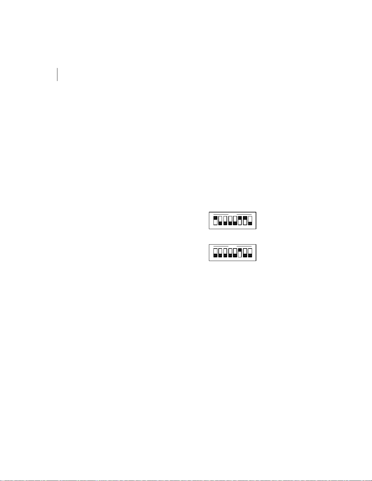
The connection to the software in the server is made using a plug-in card that can exchange
data at the radio's maximum speed. The ESCC card is available in both ISA and PCI bus
versions, and is usually pre-configured and mounted in the server by FleetMind personnel.
Figure2-1 DIP switch setting for ESCC PCI Card.
CLOCK CONTROL
485 CONTROL
ON
1 2 3 4 5 6 7 8
SW5
ON
1 2 3 4 5 6 7 8
SW6
Page 17
FLEETLINK ACCESS POINT 300
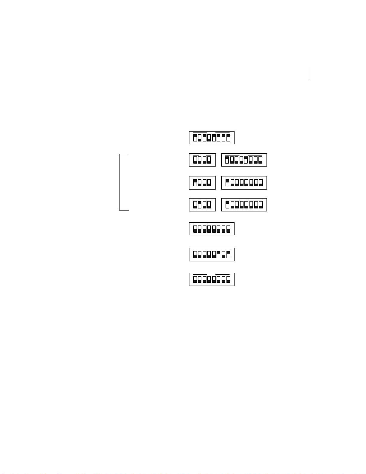
Figure2-2 DIP switch setting for ESCC ISA Card
17
Installation Guide
ADRESS SELECT = 280H
IRQ SELECT
IRQ = 5 (Default)
IRQ SELECT
IRQ = 10
IRQ SELECT
IRQ = 11
DMA SELECT
MODE # 1 CONFIG
MODE # 1 CONFIG
ON
1 2 3 4 5 6 7 8
SW1
ON
1 2 3 4 1 2 3 4 5 6 7 8
SW2 SW3
1 2 3 4
SW2
ON
1 2 3 4
SW2
ON
1 2 3 4 5 6 7 8
SW4
ON
1 2 3 4 5 6 7 8
SW5
ON
1 2 3 4 5 6 7 8
SW6
ON
ONON
1 2 3 4 5 6 7 8
SW3
ON
1 2 3 4 5 6 7 8
SW3
Software
The required software is usually pre-installed in the server PC by FleetMind personnel.
This software controls the transmit/receive operation of the Access Point 300 radio and
sends and receives data between the Manager applications in the server and the Copilots in
the trucks.
Page 18

CHAPTER 2
18
Introduction
Cable and Splitter
The cable and splitter connect the radio box to the server, and splits the connections for
ESCC card, Installation Terminal or PC com port and power inputs. A 25-wire, low
capacitance, computer-grade cable is run from the server room to the Access Point 300 box.
There is a DB25 female connector at the Access Point 300 end and a DB25 male connector at
the server end connected pin to pin.
Standard cable lengths are 3.75 meters (12.3 feet) part number: 926-0026-00.00 and 30
meters (100 feet) part number: 926-0026-01.00. More than one cable can be plugged end to
end, up to a maximum length of 90 meters (300 feet). This cable can be supplied by
FleetMind made to a length determined from a site survey. If the server needs to be
relocated later, this cable can be extended with a standard DB25 male-female cable. At the
server end, a FleetMind splitter separates the connections according to function.
The splitter, part number: 926-0025-00.00 or 926-0025-00.01 provides two DB25 female
connectors one to mate with the ESCC Port 1 Male connector and one to mate with the
Access Point 300 cable Port Male connector. In addition, it has a DB9 female connector for
the frequency setting with a special Access Point Installation Terminal or a PC com port
and one or two power jacks to provide power supplies i.e. one for the Access Point 300
radio box with 926-0025-00.00 or 926-0025-00.00 and one, only with 926-0025-00.00, for the
Installation Terminal, if it is used.
Page 19

FLEETLINK ACCESS POINT 300
19
Installation Guide
Access Point Installation Terminal
Note Access Point Installation Terminal could be used only if you have the splitter part
number: 926-0025-00.00. With the splitter part number: 926-0025-00.00 the Manager ShortRange RF Access Point Properties should be used
The Access Point Terminal includes the AcPt300 remote control and status program. It has
a single screen for all normal operation, making it easy to use. Following is an explanation
of what you see on the terminal screen and how to use the terminal:
• Connected to:
The Access Point 300 sends its program version when first powered up. This
program version will be displayed on the first line below the title if the Terminal
is connected and already powered.
• <Ask Status>
When you press Enter with <Ask Status> highlighted, the terminal requests a
status report from the Access Point 300. On receiving the status request, if the
firmware version supports this feature, the Access Point 300 circuit reads the
analog values and sends them with the channel number and system states
(control lines) over the RS-232 connection part of the cable back to the terminal.
• <Config>
When you press Enter with <Config> highlighted, the terminal switches to the
Configuration Screen. This screen allows you to alter the look of the display,
calibrate the temperature reading (future option), and turn on or off key
backlighting or beep.
• SetChannel
If the radio's frequency channel needs to be changed, type the channel number
from 1 to 7 and press Enter. A status report is automatically sent back by the
Access Point 300 to update the channel number display (shown after Now:)
• AutoReport (Future use)
Type the time interval for automatic status reporting by the Access Point 300, in
tenths of a second, from 10 to 250, then press Enter. For example, type 50 for once
every 5 seconds or 250 for once every 25 seconds. To turn off automatic status
report generation, type 0 and press Enter.
Page 20

CHAPTER 2
20
Introduction
• Alarm Status
This line is used to display the status of alarms (requires special firmware in the
Access Point). Normal indicates that there are no abnormal conditions (no
alarms). Too Hot! indicates that the temperature reading sent in the status report
exceeds a set limit. Low Voltage! indicates that the input voltage at the Access
Point 300 end of the cable is too low for reliable operation. Tamper Alarm!
indicates that the tamper switch has been activated (box cover removed).
• Analog Values (requires special firmware in the Access Point, dummy values are
displayed with standard firmware).
Example: Temp 020 RSSI 000 13 V indicates that the temperature inside the
AccessPoint300 box is approximately 20°C, the RSSI is 0 (radio is off) and the
input power voltage is between 13 and 13.9 V.
• Digital States
The line dtr DSR cts - rts Rx indicates the current state of input and output
control lines the two radio states. Uppercase letters indicate a control line in the
active state and lowercase letters indicate a control line in the inactive state.
The current state of the Microcontroller /Standby and Tx//Rx outputs to the
RXA-300 are also displayed: —indicates that the radio is in standby (off) mode;
On normally appears when the server activates DTR and the radio is turned on
by the microcontroller; Rx indicates the receive state of the Rx/Tx radio control
line. The terminal can display what states the Access Point 300 is receiving for the
control signals DTR and RTS, and what it is outputting for CTS and DSR. This
information is helpful for troubleshooting the wiring when there is a difference
between what the server expects and what the Access Point 300 card reports.
Page 21
FLEETLINK ACCESS POINT 300
Installation Guide
21
Manager Short-Range RF Access Point Properties
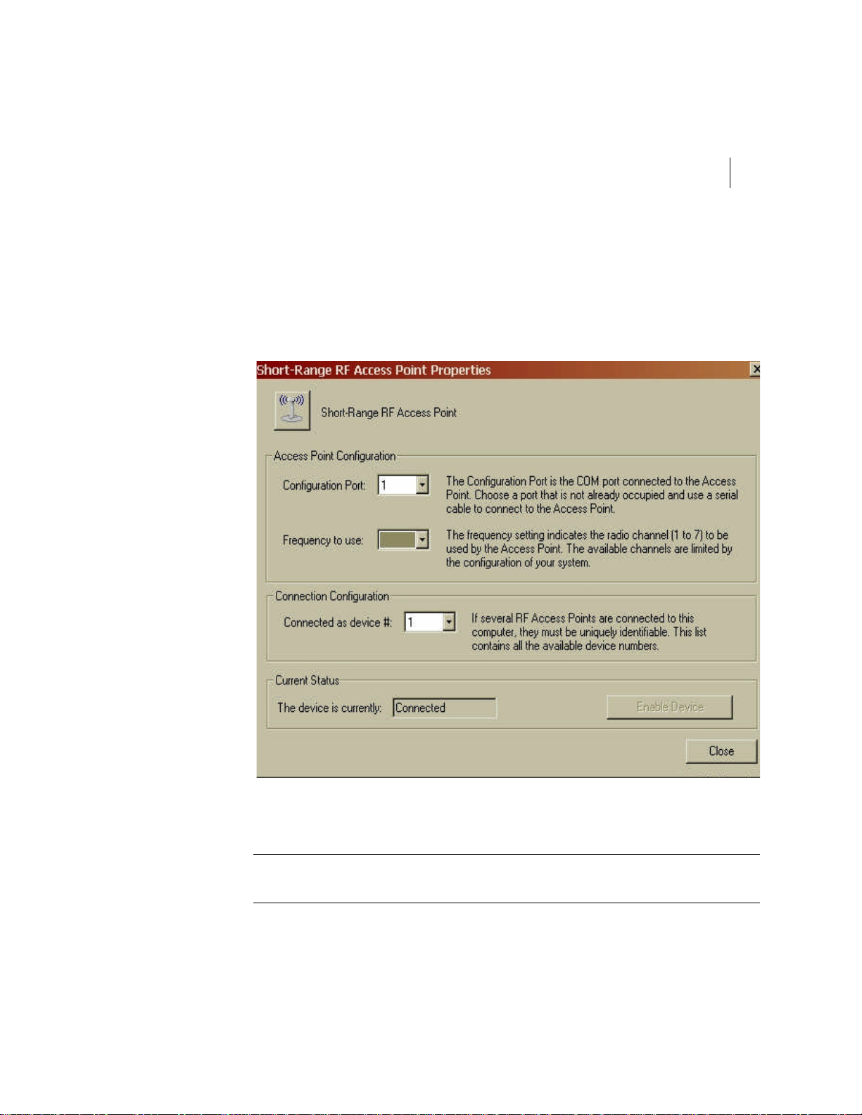
The Manager Short-Range RF Access Point Properties, available in the server software,
includes the AcPt300 remote control to set the frequency that will be used by the Access
Point for the normal operation. See Fleetlink Report Manager User Guide for more
information.
Figure2-3 Short-Range RF Access Point Properties window.
Note Manager Short-Range RF Access Point Properties could be used with both splitter
versions. No extra power supply is needed.
Page 22

CHAPTER 2
22
Introduction
Page 23

Chapter 3
Installation
Page 24

CHAPTER 3
24
Installation
Introduction
This chapter provides installation considerations for the Access Point 300
antenna, as well as detailed instructions for installing the Access Point 300.
Installation Considerations
Prior To Installation
An installation plan must be approved by the customer and reviewed by Fleetmind
technical support. The following points must be considered:
• Antenna location. (roof, outside wall of the building)
• Which antenna will be used?
• Coax cable and data cable length and where they will be routed?
• Permission to make a hole through the building structure?
• Where the manager is located vs. the Access Point 300?
• Which frequency (channel) will be used?
• Site survey for RF coverage if possible
• The PC server must be configured with the correct software, settings and
installed in the server room.
Caution If there is no possibility to install the antenna as we recommended, the customer
must absolve FleetMind of responsibility in writing and assume the risk that the system
will not work properly as planned or not work at all.
Page 25

FLEETLINK ACCESS POINT 300
25
Installation Guide
Antenna Installation
Proper antenna location maximizes antenna performance. A site survey with portable
equipment should be performed prior to installation to determine the best location and
provide assurance that the coverage will be satisfactory. When you determine the proper
antenna location, consider the environment in which the device will be used.
Environments can vary significantly, and incorporating the antenna is an integral part of a
successful installation. Use only the antenna supplied, part number 891-003 antenna with
891-004 magnetic mount base or part number 891-023 omni directional antenna. Also for
temporary installation, like a trial, a suction cup or glass mount antenna, part number 891001 (discontinued) or 891-025 could be used. Ask Fleetmind technical support for guidance
concerning a temporary installation.
When you are installing an antenna, you should consider the following issues:
• Vertical polarization
Because the Access Point 300 network is based on a vertically polarized
radio-frequency transmission, the antenna should be oriented vertically and
upward.
• Proximity to active electronics
You should position the antenna as far as possible from the computing devices’
active electronics.
• Transmission interference
To prevent interference from the antenna into the Access Point 300 during
transmission, the antenna must be placed a minimum of 8 in. (20 cm) away from
the Access Point 300. For best performance, the antenna should be placed more
than 12 in. (30 cm) away from the Access Point 300.
• Device position
Fleetmind recommends that you install the Access Point 300 inside the building
in a temperate location that is out-of-the-way, but accessible for service. This
location must be within the antenna coax cable length distance from the antenna.
Above the false ceiling and high on the truck terminal wall are two possible
mounting locations.
Page 26

CHAPTER 3
26
Installation
• Antenna Installation
If a ground plane omni antenna type is used, the antenna should be installed
outside on top of a metal mast at least 10' (3 m) height and 3/4'' to 2 3/8''(1.9 to 6
cm) of diameter, where there is a clear view of the area required to be in RF
coverage. Depending on the building site configuration, a tripod or metal clamp
could be used to install the antenna. Using a metal mast with the antenna to raise
the antenna above the roof, will allow a clear view, to achieve its design
performance and optimize the system's coverage.
If the mag mount type antenna is used, the antenna should be installed outside
on a metal ground plane at least 12"x12" (30 X 30 cm) size, where there is a clear
view of the area required to be in RF coverage. Using a metal ground plane for
the antenna will allow it to achieve its design performance and optimize the
system's coverage. Galvanized or painted thick steel (14 ga. or thicker) is
recommended so that the magnetic mount can attach securely, without relying
on additional means to hold it in place.
This ground plane could be a steel roof or a plate on a bracket attached to the top
of a building, or a pole. It must be placed where the antenna will always be a
minimum of 8 in. (20 cm) away from human contact, typically 15 feet. or more
above ground level.
• Antenna height
For best performance, the antenna should be installed between 15 feet and 50 feet
(4.6 m and 15.3 m) from the ground.
• Antenna location
The antenna should be visible in a straight line from the truck at any place where
the coverage is desired. Otherwise performance degradation will occur. Usually,
that could be achieved by placing the antenna near a sidewall of the building and
this is what we recommend. Select the sidewall face where most operations are
done with the trucks. If it not possible to have the antenna within 10 feet of the
sidewall of the building, please contact customer support for an evaluation of the
performance degradation.
Caution For each foot (.3 m) in from the sidewall, you need to rise the antenna height by 2
feet (.6 m) from the roof. Also, you should not exceed the 50 feet (15.3 m) antenna height
from the ground.
Page 27
FLEETLINK ACCESS POINT 300
27
Installation Guide
• Coverage considerations
The desired coverage must favour the location where the trucks spend most of
the time of their operations in the yard. (parking, dock loading) This will give
more visibility time for the system to complete its data transfers. Both departure
and arrival operations must be considered. Any obstacle between the truck and
the Access Point antenna could compromise the reliability and the performance
of the system.
Caution The coax cable run should not exceed 75 feet (22.8 m) or 3.1dB of loss. Example: A
75 feet Belden 9913 RG-58C 50 ohms coax cable typical loss at 900 MHz is 3.07dB.
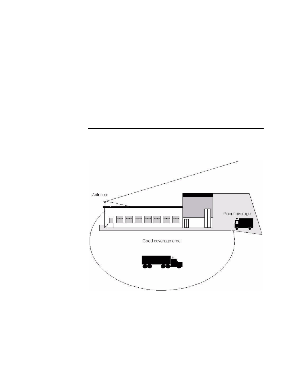
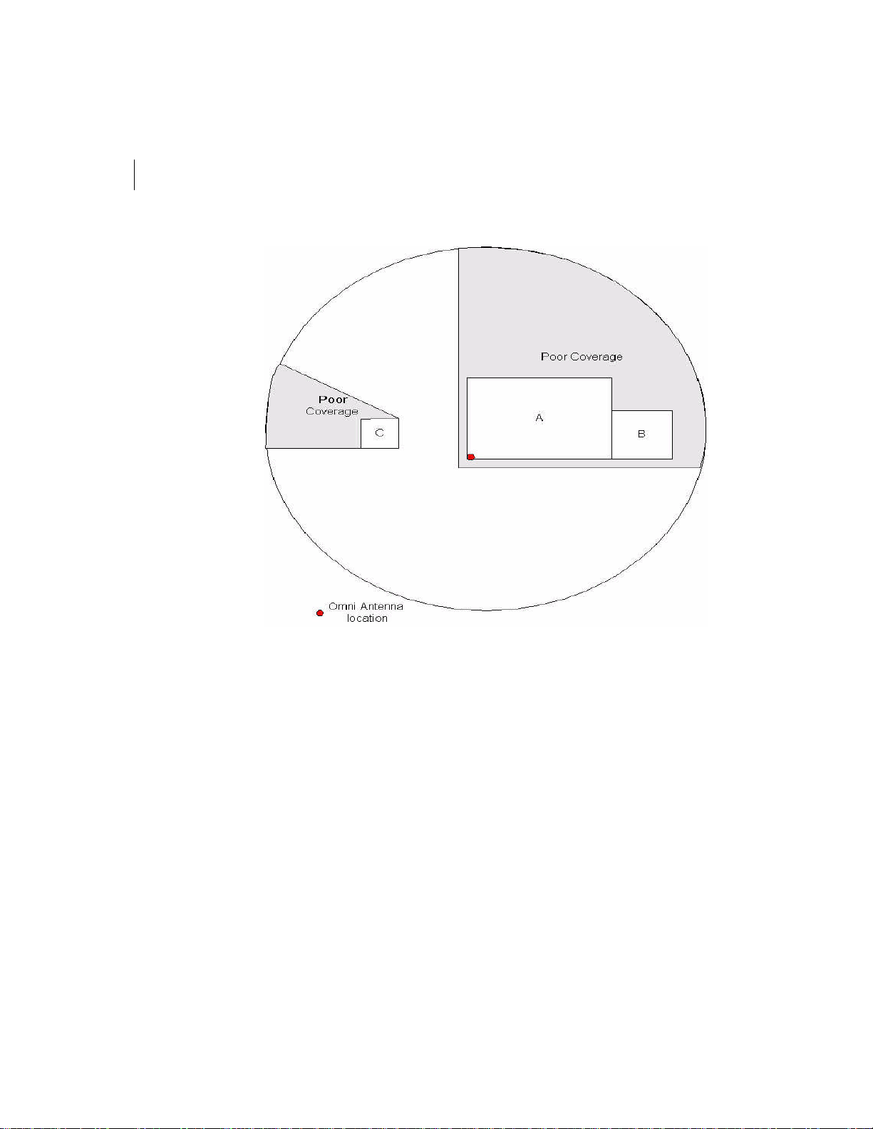
Figure 3-1 Typical antenna coverage
The figure above shows a typical antenna coverage pattern. In this case the antenna is
located at one corner of the building near the dock. At the right side we have the corporate
office portion of the building which is higher than the terminal section. If a truck is beside
that building portion, the coverage will be poor or nil.
Page 28
CHAPTER 3
28
Installation
Figure 3-2 Top view of coverage area with the antenna installed at one building corner
The figure above shows a typical antenna coverage. In this case, the antenna is located at
one corner of the building (A) near the dock. At the right side we have the corporate office
portion (B) of the building which is higher than the terminal section. If a truck is beside that
building portion, the coverage will be poor or nil. At the left side of the antenna there is an
auxiliary building (C). That building also could cause poor coverage, behind it.
Page 29
FLEETLINK ACCESS POINT 300
Installation Guide
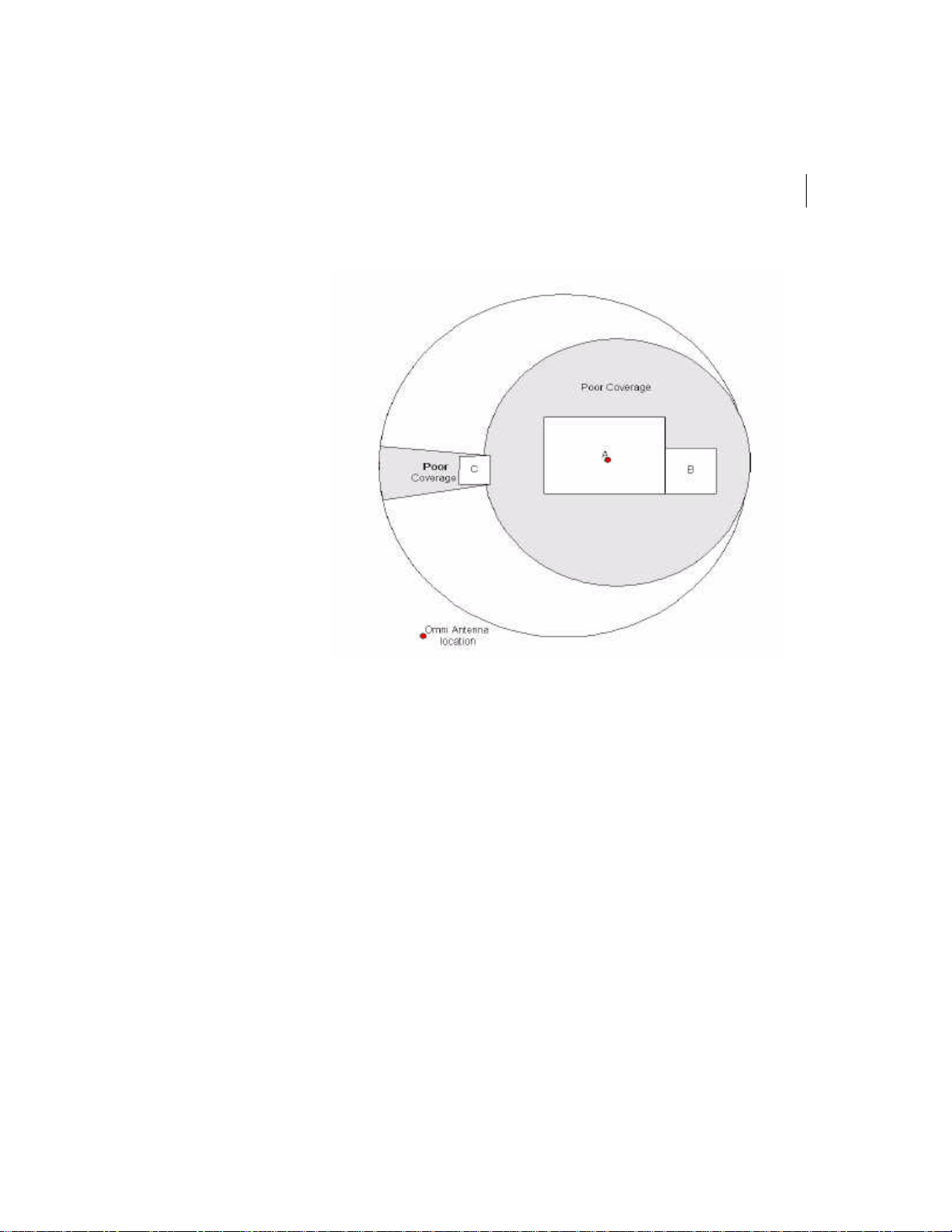
Figure 3-3 Top view of coverage area with the antenna installed at the building center
29
The figure above shows a not recommended antenna installation and the poor coverage
that results. In this case, the antenna is located at the center of the building (A)roof. Because
the antenna is located at the center of the building, the straight line visibility between the
truck and the access point antenna is compromised around close to the area of the building
(A and B). At the right side we have the corporate office portion (B) of the building which is
higher than the terminal section. If a truck is beside that building portion, the coverage will
be poor or nil. At the left side of the antenna there is an auxiliary building (C). That
building also could cause a poor coverage region.
Page 30

CHAPTER 3
30
Installation
Installing the Access Point 300
Access Point 300 System Components
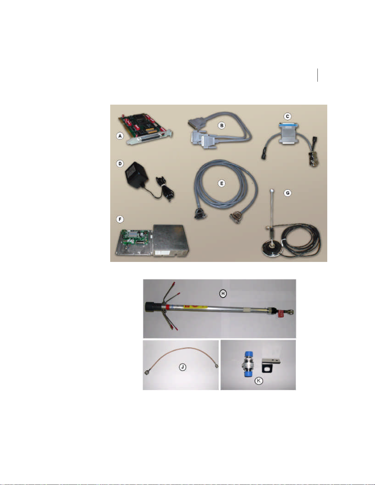
The components that usually make up the Access Point 300 are—
A FASTCOMM ESCC card (Installed inside the PC server.)
B FASTCOMM ESCC 2-port cable
C Splitter
D AC-DC adapter
E DB25 cable, 12 feet (3.75 m) or 98 feet (30 m)
F Access Point 300 with cover
G Antenna mag mount (whip, mag mount base and coax cable)
or
H Omni antenna with ground plane
I 50 Ohm low loss transmission coax cable with appropriate connectors (N-female/
N-female) maximum of 50 feet (13.5 m) picture not shown
J Surge protector transition coax cable (TNC-male and N-male)
K Lightening arrestor
Tip Check all items against your shipping order to ensure that you have received all the
components. If a component is missing, contact customer support. Inspect the equipment
for visible damage. If you notice any damage, contact customer support.
Note Depending on the type of installation, some items must be provided by the installer.
Example: Tie wrap, coax cable with the appropriate connectors, mast, screws...
Page 31
FLEETLINK ACCESS POINT 300
Figure 3-4 Access Point 300 System Components
31
Installation Guide
Page 32
CHAPTER 3
32
Installation
Installation Procedure
Tip The DB25 cable must be routed inside and the coax cable must be routed inside and
outside the building structure before plugging the antenna and the DB25 cable. Pay
attention to the connector polarity of the DB25. (Male end is toward the PC and the female
end is toward the Access point)
Caution Do not power the Access Point without its antenna connected.
To install the Access Point 300:
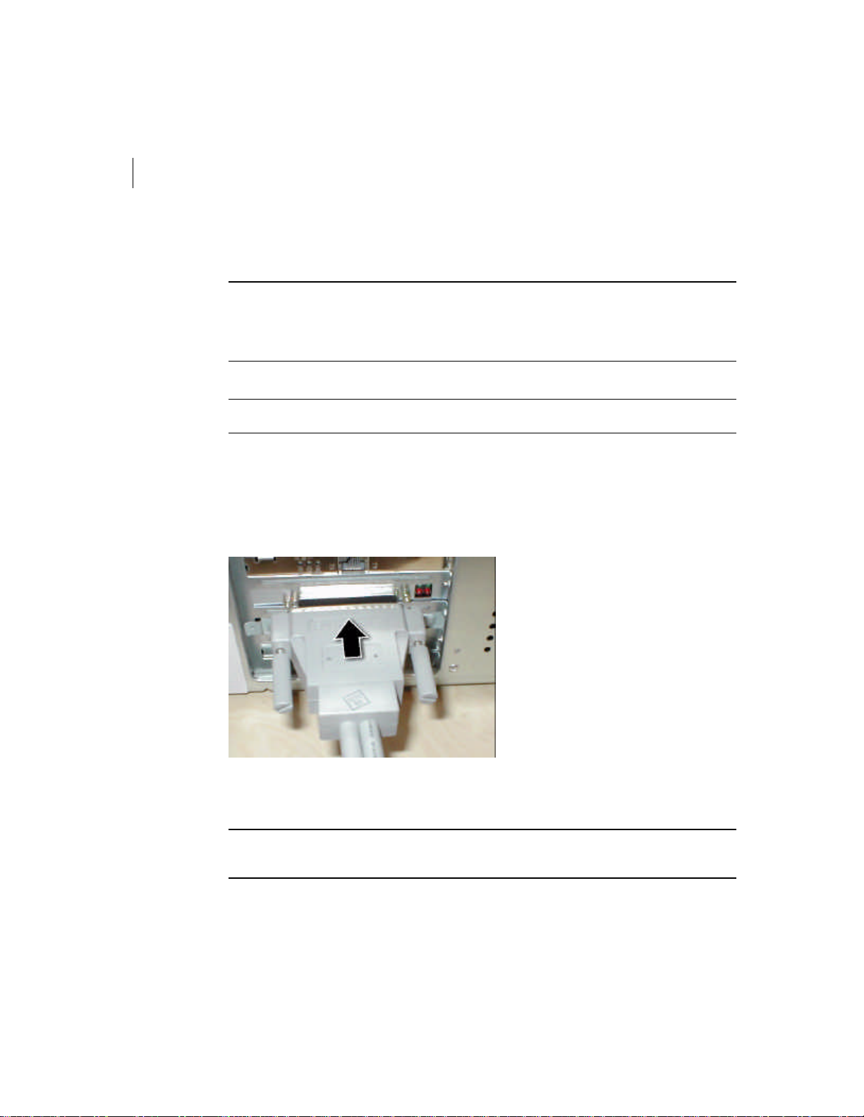
1 Plug the FASTCOMM end of the ESCC 2-port cable into the ESCC card, (which
usually was already installed in your computer by FleetMind personnel), and screw
on the thumb screws.
Figure 3-5 ESCC Cable’s FASTCOMM Connector
Tip If the Sever is up and running, a quick check could be done by connecting the Access
Point with it components temporarily.
Page 33
FLEETLINK ACCESS POINT 300
33
Installation Guide
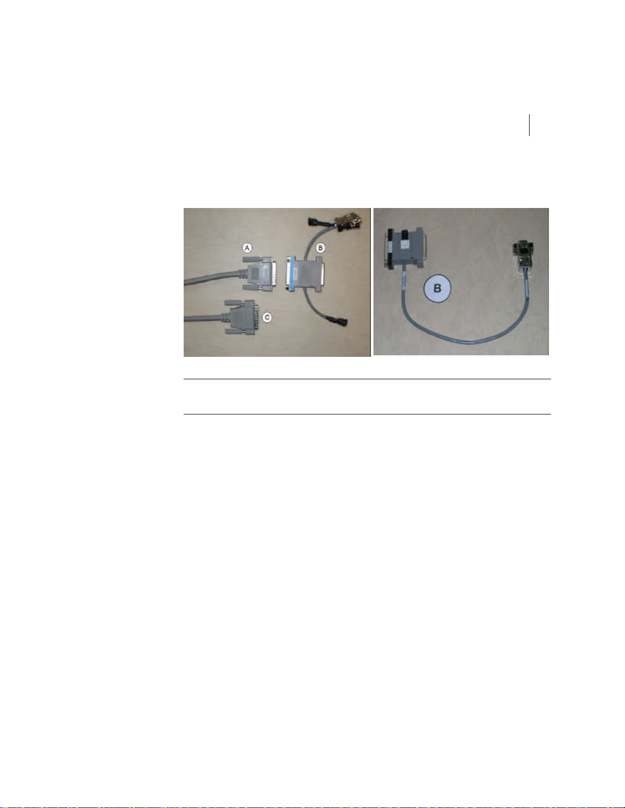
2 Plug the PC SIDE of the splitter (B) into the PORT1 connector of the ESCC 2-port cable
(A) and screw on the thumb screws.
Figure 3-6 Splitter and ESCC Cable’s PORT1 Connector
Caution Do not connect the splitter to the ESCC cable’s PORT2 connector (C). If you do
this, the Access Point 300 will not function.
Page 34
CHAPTER 3
34
Installation
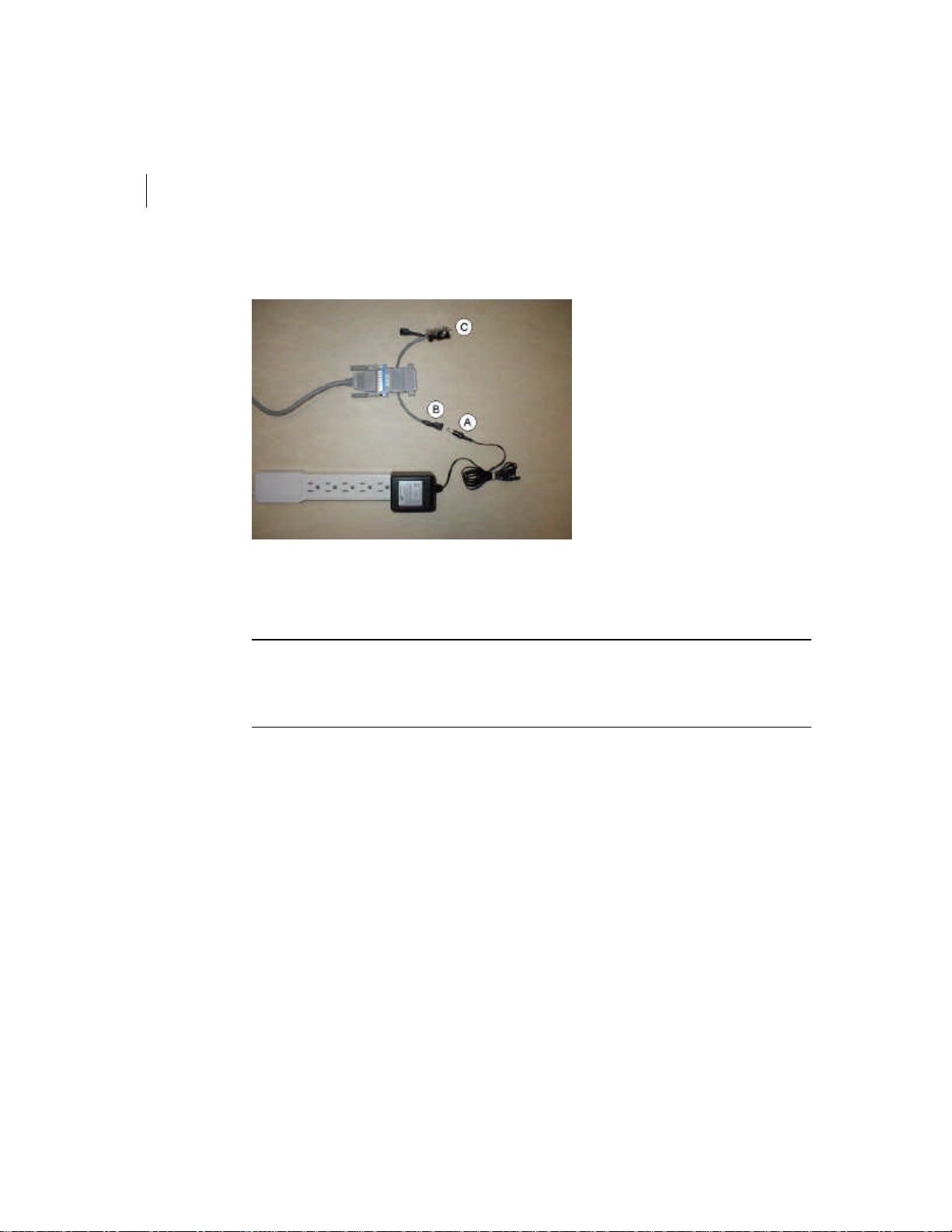
3 Connect the splitter’s DB9/power connector (C) to an available PC serial port.
Figure 3-7 AC Adapter
4 Connect the provided AC-DC adapter (A) to the power connector (B) as shown above,
at the end of the installation process. In the case of splitter model 926-0025-00.01
connect to the only available power connector.
Caution Do not use the power connector near the DB9 connector, except when using a
special Access Point test Terminal. The splitter’s DB9/power connector (C) is for diagnostic
and channel selection purposes only and must be always connected to an available PC
serial port or temporarily to an Access Point Test Terminal.
Page 35
FLEETLINK ACCESS POINT 300
Installation Guide
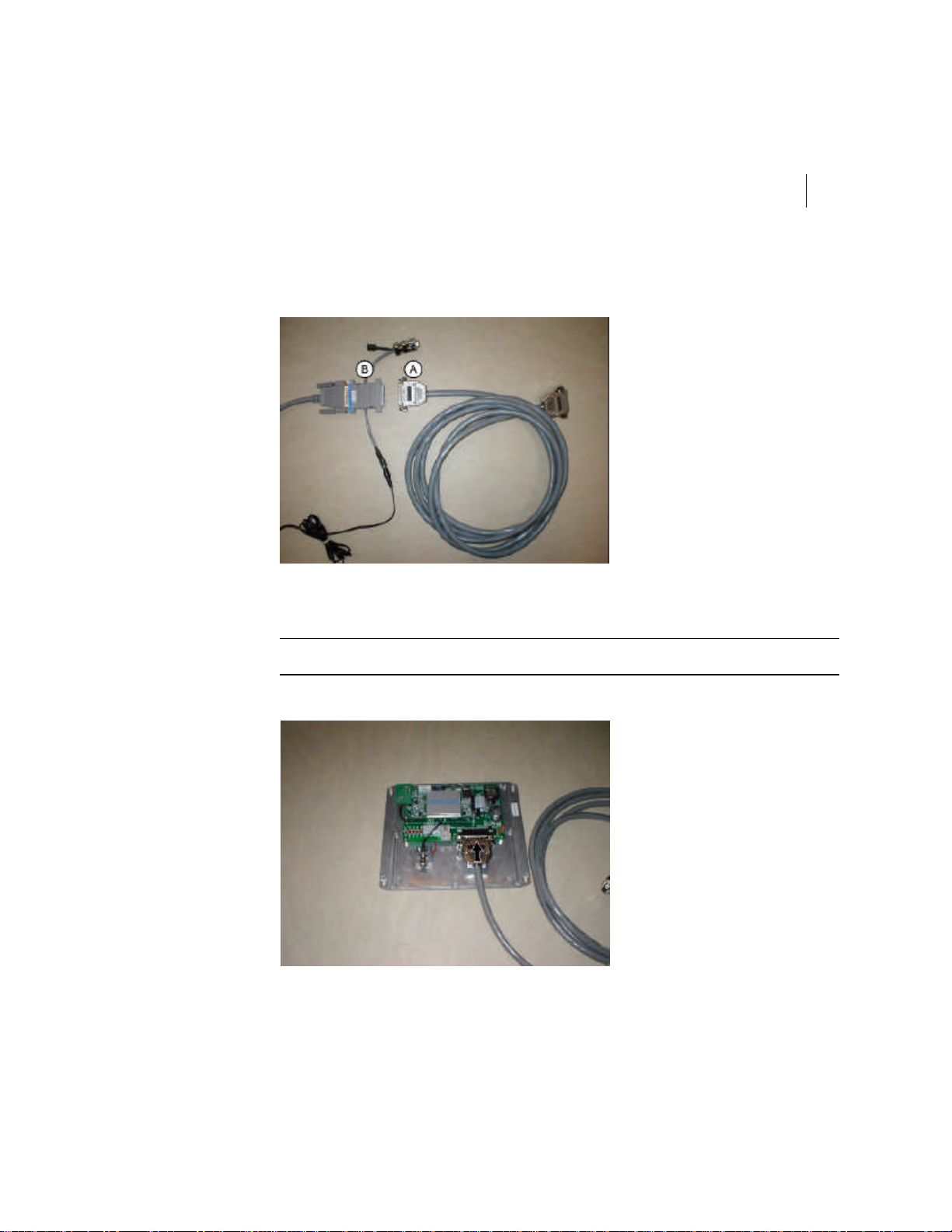
5 Connect the male end of the DB25 cable (A) into the free end of the splitter (B) and
tighten the DB25 screws.
Figure 3-8 Splitter and DB25 Cable
6 Connect the female end of the DB25 cable into the Access Point 300.
35
Note The location of the Access Point box should be determined prior to the connection.
Figure 3-9 DB25 Cable connected inside the Access Point
Page 36
CHAPTER 3
36
Installation
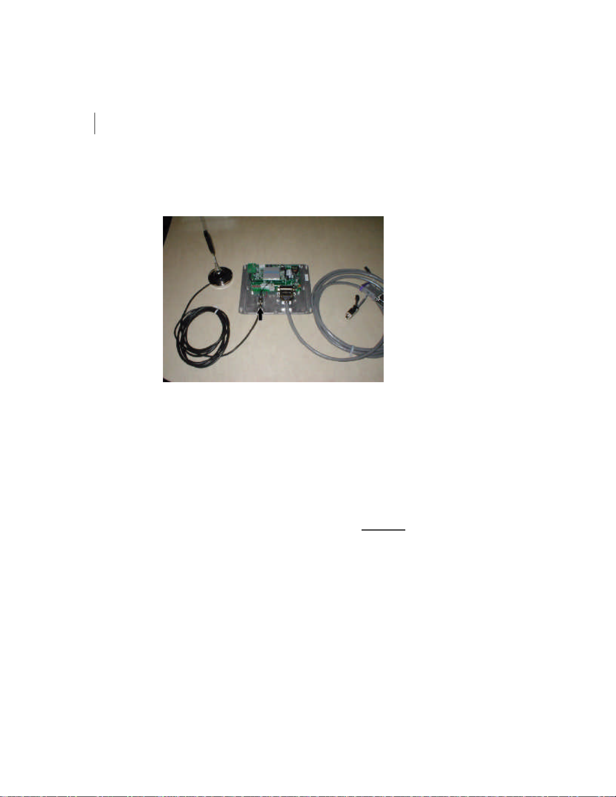
7 Connect the antenna’s coaxial cable to the RF connector on the Access Point 300 or
connect the extension coax cable onto the external connector on device.
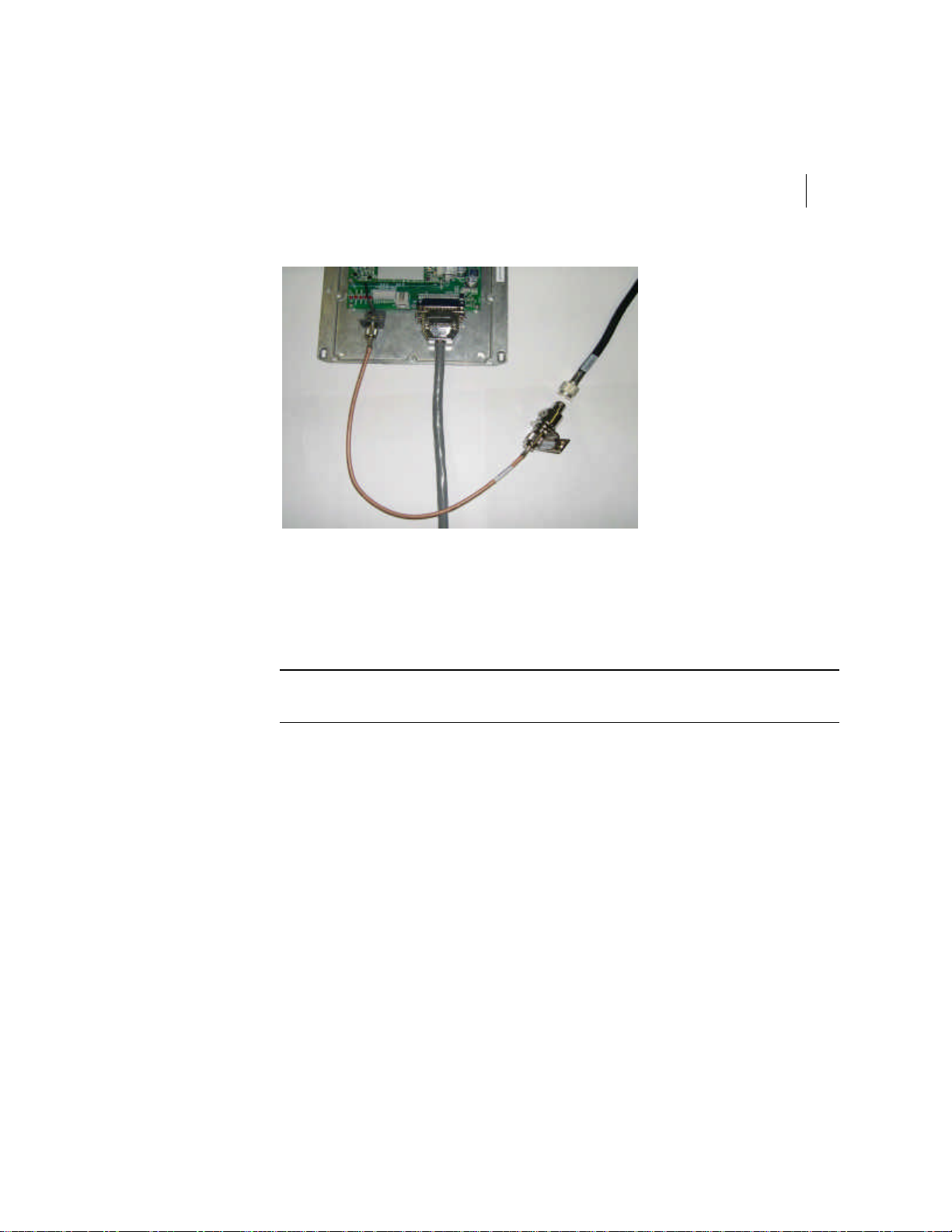
Figure 3-10 Antenna’s coaxial cable connection
8 If the Omni antenna with ground plane is used, install the surge protector at the
recommended position, near the device side.
a Ground the surge protector adaptor to the ground of the building and attach it
with its mounting brackets. Recommended grounds are the utility company
ground, a ground rod, well casings , and a cold water pipe that is a continous
water pipe. A note of caution: sometimes the metal cold water pipe has been
repaired and/or extended with PVC piping. A thorough investigation of a cold
water pipe ground is important since the PVC repair or extensions may be
covered by drywall. Grounds that are unacceptable include sprinkler pipes, PVC
pipe, conduit, buried wire and any ground that cannot be verified. All ground
wires must be as short as possible and it imperative that the ground wire not be
coiled nor looped. Regarding the diameter of the ground wire, the larger the
better.
b Connect one side of the surge protector to the surge protector transition coax
cable (transition cable) and the other side to the 50 Ohm low loss transmission
coax cable (transmission coax cable).
Page 37
FLEETLINK ACCESS POINT 300
Installation Guide
Figure 3-11 Surge protector and extension coax cable connection
9 Install the omni antenna with ground plane at the location stated in the installation
plan and install the transmission coax cable between the antenna and the surge
protector.
a Inspect the antenna feed connector to determine that it will mate with the end of
your transmission coax cable.
37
Caution Do not remove any connector or cable from the antenna as they are all part of
your antenna.
b Assemble the antenna, including mounting clamps, as shown on the assembly
picture. Tightening torques provided must be adhered to when assembling and
installing the antenna. Drain holes in the mast base and/or radiating element
must face downward and remain unobstructed at all times.
Page 38

CHAPTER 3
38
Installation
Figure 3-12 Antenna Assembly with mast.
c Always protect the cable harness and radiating element from damage when
moving, lifting or resting the antenna.
d Connect the antenna connector to the transmission coax cable connector and use
waterproof tape and after, an electrical tape, to wrap around both connectors
tightly.
Figure 3-13 Waterproof tape around antenna and the transistion coax cable connectors
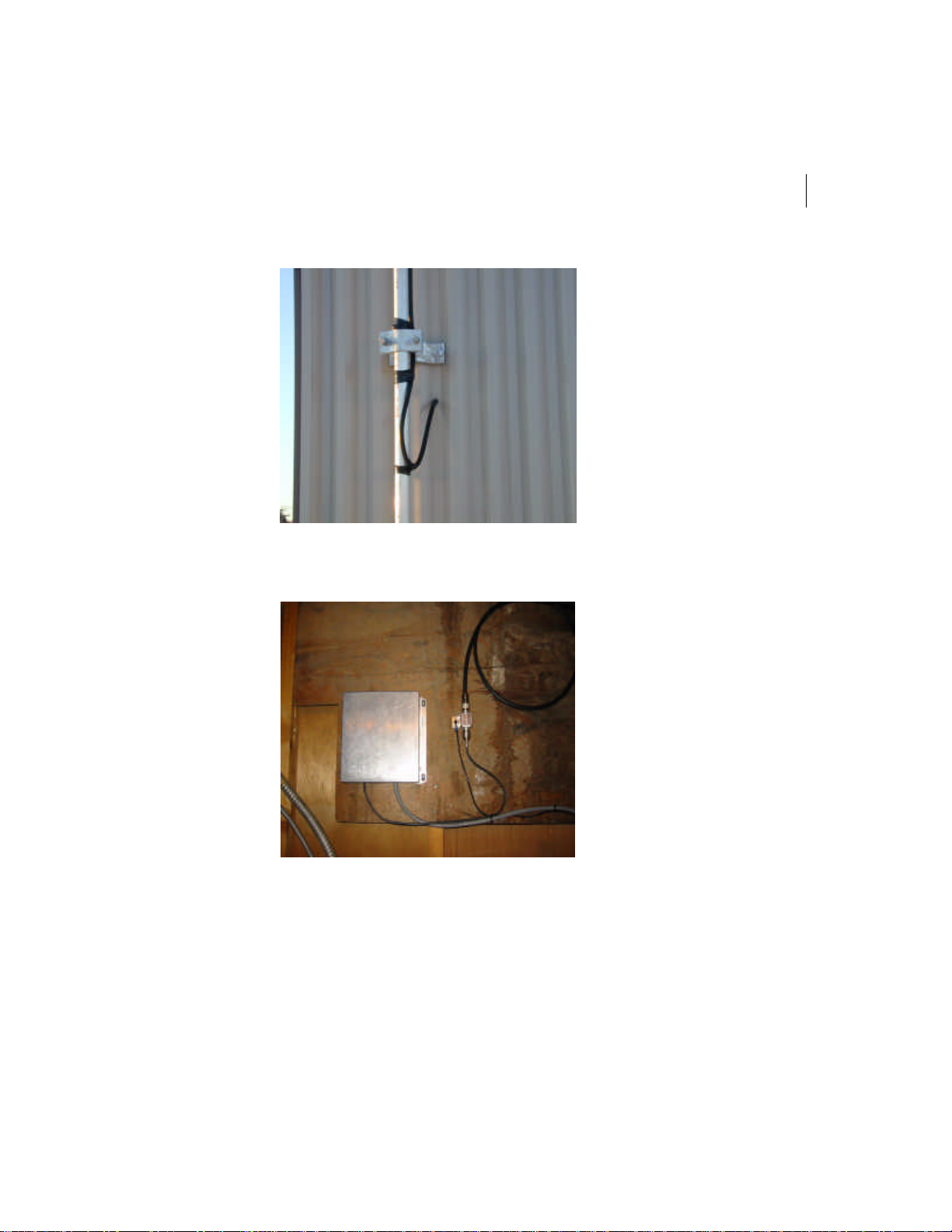
e Use of a drip loop on the antenna cable helps water run off the cable, thus
preventing water from running into the hole.
Page 39
FLEETLINK ACCESS POINT 300
39
Installation Guide
Figure 3-14 Drip loop on the antenna cable.
10 Put the cover back and install the Access Point 300 as recommended in the previous
section.
Figure 3-15 Access Point typical installation with surge protector.
11 Plug the AC adapter (A) into the splitter’s power connector (B) see Figure 3-7on
page34.
12 Verify that the system is able to communicate with a truck. Also, it is recommended to
take pictures of the installation, to do a coverage study with the final installation, and
keep a record for future reference.
Page 40

40
NOTES
 Loading...