


FMI-HDP
Installation and Users Guide
4-CHANNEL MOBILE DIGITAL VIDEO
RECORDER WITH REMOVABLE HARD DRIVE
AND OPTIONAL SD CARD
March 2008
Version 2.0
Fleet Management Inc.
770-263-8118
sales@AmericanBusVideo.com
AmericanBusVIdeo.com
ii
LIMITATION OF LIABILITY
THE INFORMATION IN THIS PUBLICATION IS BELIEVED TO BE ACCURATE IN ALL
RESPECTS; HOWEVER, WE CANNOT ASSUME RESPONSIBILITY FOR ANY
CONSEQUENCES RESULTING FROM THE USE THEREOF. THE INFORMATION
CONTAINED HEREIN IS SUBJECT TO CHANGE WITHOUT NOTICE. REVISIONS OR
NEW EDITIONS TO THIS PUBLICATION MAY BE ISSUED TO INCORPORATE SUCH
CHANGES.
iii
WARNINGS AND CAUTIONS
TO REDUCE THE RISK OF FIRE OR ELECTRIC SHOCK, DO NOT
EXPOSE THIS PRODUCT TO RAIN OR MOISTURE. DO NOT INSERT
ANY METALLIC OBJECTS THROUGH THE VENTILATION GRILLS OR
OTHER OPENINGS ON THE EQUIPMENT.
CAUTION
EXPLANATION OF GRAPHICAL SYMBOLS
The lightning flash with arrowhead symbol, within an
equilateral triangle, is intended to alert the user to the
presence of un-insulated “dangerous voltage” within the
product’s enclosure that may be of sufficient magnitude
to constitute a risk of electric shock to persons.
The exclamation point within an equilateral triangle is
intended to alert the user to the presence of important
operating and maintenance (servicing) instruction in the
literature accompanying the product.

iv
WARNINGS AND CAUTIONS .....................................................iii
CAUTION .................................................................................iii
EXPLANATION OF GRAPHICAL SYMBOLS ..........................iii
MOBILE DIGITAL RECORDER DESCRIPTION........................... 2
Feature Summary ..................................................................... 3
PRODUCT CONFIGURATIONS .................................................. 4
MDVR with Removable hard drive Storage............................... 4
MDVR with Removable Single SD Card.................................... 4
DIGITAL RECORDER FRONT PANEL OPERATION .................. 6
BASIC ON SCREEN DISPLAY.................................................... 8
SYSTEM STARTUP FEATURES ............................................... 10
INSTALLING SYSTEM UPGRADES ...................................... 10
Automatic Movie Playback ...................................................... 11
AUTOMATIC CONFIGURATION SCRIPT .............................. 11
MDVR MENU STRUCTURE ...................................................... 13
REMOVABLE HARD DRIVE................................................... 29
FILE STRUCTURE ......................................................... 29
FTP COMMANDS................................................................... 31
TELNET COMMANDS ............................................................ 32
Examples for PLAY command ..................................... 33
TELNET PARAMETER SPECIFICATION ...................... 34
ETHERNET STREAMING PROTOCOL.................................. 37
HARDWARE INSTALLATION ................................................... 39
MDVR CONNECTION................................................................ 41
BACK PANEL CONNECTION DETAIL ..................................... 42
EQUIPMENT SPECIFICATIONS ............................................... 43

v
IMPORTANT SAFEGUARDS
1. READ AND RETAIN INSTRUCTIONS
Read the instruction manual before
operating the equipment. Retain the
manual for future reference.
2. CLEANING
Turn the unit off and unplug from the
power outlet before cleaning. Use a
damp cloth for cleaning. Do not use
harsh cleansers or aerosol cleaners.
3. ATTACHMENTS
Do not use attachments unless
recommended by manufactured as
they may affect the functionality of the
unit and result in the risk of fire,
electric shock or injury.
4. MOISTURE
Do not use equipment near water or
other liquids.
5. ACCESSORIES
Equipment should be installed in a
safe, stable location. Any wall or shelf
mounting accessory equipment should
be installed using the manufacture’s
instructions. Care should be used
when moving heavy equipment.
Quick stops, excessive force, and
uneven surfaces may cause the
equipment to fall causing serious
injury to persons and objects.
6. VENTILATION
Openings in the equipment, if any, are
provided for ventilation to ensure
reliable operation of the unit and to
protect if from overheating. These
openings must not be blocked or
covered
7. POWER SOURCES
The equipment should be operated
only from the type of power source
indicated on the marking label. If you
are not sure of the type of power
supplied at the installation location,
contact your dealer. For equipment
designed to operate from battery
power, refer to the operating
instructions.
8. GROUNDING OR POLARIZATION
Equipment that is powered through a
polarized plug (a plug with one blade
wider than the other) will fit into the
power outlet only one way. This is a
safety feature. If you are unable to
insert the plug fully into the outlet, try
reversing the plug. Do not defeat the
safety purpose of the polarized plug.
Alternate Warning: If the equipment is
powered through a three-way
grounding-type plug, a plug having a
third (grounding) pin, the plug will only
fit into a grounding-type power outlet.
This is a safety feature. Do not defeat
the safety purpose of the groundingtype plug. If your outlet does not have
the grounding plug receptacle, contact
your local electrician.
9. CORD AND CABLE PROTECTION
Route power cords and cables in a
manner to protect them from damage
by being walked on or pinched by
items places upon or against them.
10. LIGHTNING
For protection of the equipment during
a lightning storm or when it is left
unattended and unused for long
periods of time, unplug the unit from
the wall outlet. Disconnect any
antennas or cable systems that may
be connected to the equipment. This
will prevent damage to the equipment
due to lightning or power-line surges.
11. OVERLOADING
Do not overload wall outlets and
extension cords as this can result in a
risk of fire or electric shock.
12. SERVICING
Do not attempt to service the video
monitor or equipment yourself as
opening or removing covers may
expose you to dangerous voltage or
other hazards. Refer all servicing to
qualified service personnel.


1
13. DAMAGE REQUIRING SERVICE
Unplug the equipment from the wall outlet and refer servicing to qualified service
personnel under the following conditions:
A. When the power supply cord or the plug has been damaged.
B. If liquid has spilled or objects have fallen into the unit.
C. If the equipment has been exposed to water or other liquids.
D. If the equipment does not operate normally by following the operating
instructions, adjust only those controls that are covered by the operating
instructions. Improper adjustment of other controls may result in damage to the
unit.
E. If the equipment has been dropped or the casing damaged.
F. When the equipment exhibits a distinct change in performance.
14. REPLACEMENT PARTS
When replacement parts are required, be sure the service technician uses
replacement parts specified by the manufacturer or that have the same characteristics
as the original part. Unauthorized substitutions may result in fire, electric shock, or
other hazards.
15. SAFETY CHECK
Upon completion of any service or repairs to the equipment, ask the service technician
to perform safety checks to verify that the equipment is in proper operating condition.
16. FIELD INSTALLATION
The installation of equipment should be made by a qualified service person and
should conform to all local codes.
17. IGNITION TRIGGER CONNECTION
For correct operation, it is very important to connect the main power to a constant 12V
supply (not switched) and the Ignition Trigger to the Ignition power supply (switched).

2
MOBILE DIGITAL RECORDER DESCRIPTION
The Mobile Digital Recorder is a true VCR replacement with advanced
features that take it beyond the standard lockbox-mounted VCR. The
digital recorder features four video/audio inputs and one video /audio
output. The DVR operates as a full duplex recorder/playback unit
offering these key simultaneous features:
1. Quad video channel recording up to 720 x 480 resolution recording
at up to 30 frames/sec (real time) or 1 frame/sec (time lapse) with
simultaneous audio recording.
2. Playback of single or quad channel recorded audio/video
3. Playback of unrelated .avi files (eliminates need for a separate ad
player)
4. Real time streaming to monitor live activity on any (or all) channels
5. FTP file transfer
6. TELNET for remote configuration
Up to eight simultaneous network sessions are supported where each
can independently be used for streaming, FTP or TELNET. For
example, 3 clients can all be streaming while other users are transferring
files or sending configuration commands.
Multiple trigger inputs are available that can be connected so the
recorder can be used as an event recorder. The triggered events are
also logged along with the video and audio. The unit features LED
Power and Record indicators as well as two programmable Open
Collector trigger output.
The unit has low power consumption while recording and milliamp power
consumption when powered off. The embedded operating system allows
for instant power up less than 1 second. With selectable video quality
and frame rates, the unit automatically calculates the amount of
recording time available.
Conditioned power is provided to supply 12VDC to external cameras and
other accessories such as a wireless Ethernet access point. The unit
features an Ethernet port with a built-in web server and ftp server for
archiving video, audio, and logged data.
All configurations feature removable storage media for easy video
archiving. The free MDVR Video Player software provides optimal
playback viewing of the multichannel .avi files created by the MDVR.

3
The small mechanical size allows several recorders to fit in the space of
an existing VCR or allow the unit to be mounted in a standard automotive
DIN format.
Feature Summary
• True low cost VCR replacement.
• Unparalleled Search capability with up to 90x Fast
Forward/Rewind Review.
• Optional integrated GPS position and speed tracking and
recording.
• Recording of GPS data to a video frame.
• Synchronization of the unit’s time with the GPS satellite system.
• Recording to 2.5” mobile removable hard drive media for
unmatched reliability. See
• Selectable record resolution: 720 x 480, 640 x 480, 360 x 240, or
320 x 240.
• Quad video input capabilities.
• Seven 24V tolerant configurable multi-event triggered inputs.
• Dedicated ignition trigger with configurable record
start/stop/delay
• Output trigger to control other devices or light an external LED to
indicate device status, e.g. when recording.
• Ethernet port for wired or wireless capabilities and FTP interface.
• Mobile power supply protection to allow direct connection of the
unit to a vehicles 12V power supply without the use of any
filtering.
• Mobile specific embedded operating system for unmatched
reliability, security and fast power up times in less than 1 second.
• Video authentication support via the Graphical User Interface
(GUI).
• Two RS232 interface for support of snap zoom camera, radar
guns (Custom Signal Radar only), and output of GPS
coordinates.
• Rugged Aluminum Extrusion construction designed for standard
1 DIN automotive installation.
• Thermal protection shutdown for below 0 or above 55 degrees C.

4
PRODUCT CONFIGURATIONS
MDVR with Removable hard drive Storage
This unit is distinguished by a lockable hard drive bay that holds
the portable Hard Drive Carrier. The hard drive stores all MDVR
data. It is available in a SATA or IDE configuration. The SATA
configuration holds one 2.5” SATA drive. The IDE configuration
holds two 2.5” IDE drives. Either configuration can use spinning
disks or solid state drives, for more rugged environments.
The REMOVABLE HARD DRIVE CARRIER must be locked in
place with the key to be recognized by the MDVR. Unlocking it,
even before removing it, will disable it and halt recording. The
removable hard drive mates with the desktop USB HARD DRIVE
READER. This unit operates on wall AC power and is recognized
by the computer as a mass storage device. The MDVR PLAYER
SOFTWARE can be used directly to access stored media files or
files can be copied to a more permanent location. See the section
on FILE STRUCTURE for navigation information.
MDVR with Removable Single SD Card
This unit adds to the base Removable Hard Drive unit a single SD
Card slot. The SD Card is used to extract just the recordings of
Events and for installing system upgrades.
Inserting an empty SD Card initiates copy captured data
surrounding an event. An extractable event is defined by the
MARK trigger response. A configurable pre-event and post-event
time will determine what is extracted. Under the SD Card slot is a
status LED that is initially OFF. The LED will blink Red to indicate
that Events have been recorded and are available for removal.
The LED will blink Green while the copy is in progress and stay
Green when the SD card can be removed. If the LED turns Red
instead, that means the SD card is full but there are more events
to be copied. Replacing the SD Card with another that has free
space will allow the MDVR to continue exporting the event files.
The MDVR keeps track of the events exported so it will not
indicate that events are present after they have been removed.
However, if there is a need to remove the events again, power
cycling the unit will cause the MDVR to rebuild its index and allow
the user to extract the same events again. Note: events, along

5
with all other captured video remains on the hard drive normally
even after SD event removal.
6
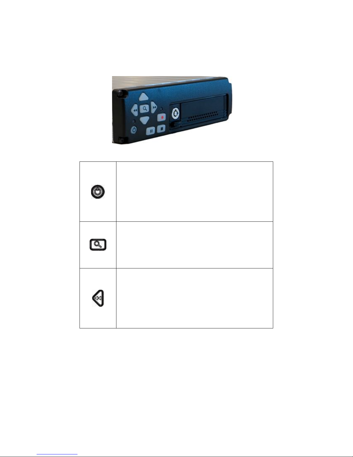
DIGITAL RECORDER FRONT PANEL OPERATION
The DVR features an illuminated keypad for easy operation in dark
environments. Below is a description of the functions of the Digital
Recorder front panel buttons. Some buttons will have different functions
depending upon if the recorder is recording, stopped, or playing back
video.
Power Button:
The unit is typically powered on by the Ignition trigger,
but may alternately be powered on by pressing the Power
Button. If manually powered on, the unit will remain
powered on until the Power Button is pressed again or 10
minutes of inactivity. Holding the Power Button in for 10
seconds will perform a hardware reset of the entire MDVR
unit.
Search/Menu Button:
Accesses the recorded video search menu. Pressing this
button once brings up the search menu. Holding this
Search / Menu Button for greater than 3 seconds brings
up the main system configuration menu where all DVR
functions can be changed and titles can be entered.
Left Arrow Key (mode dependant):
During Playback Mode: Left Arrow Key adjusts fast
reverse playback speed from 0.5X to 90x
From Pause mode Left Arrow Key is a frame step
From Record Mode: Press and hold will manually control
zoom out.
7
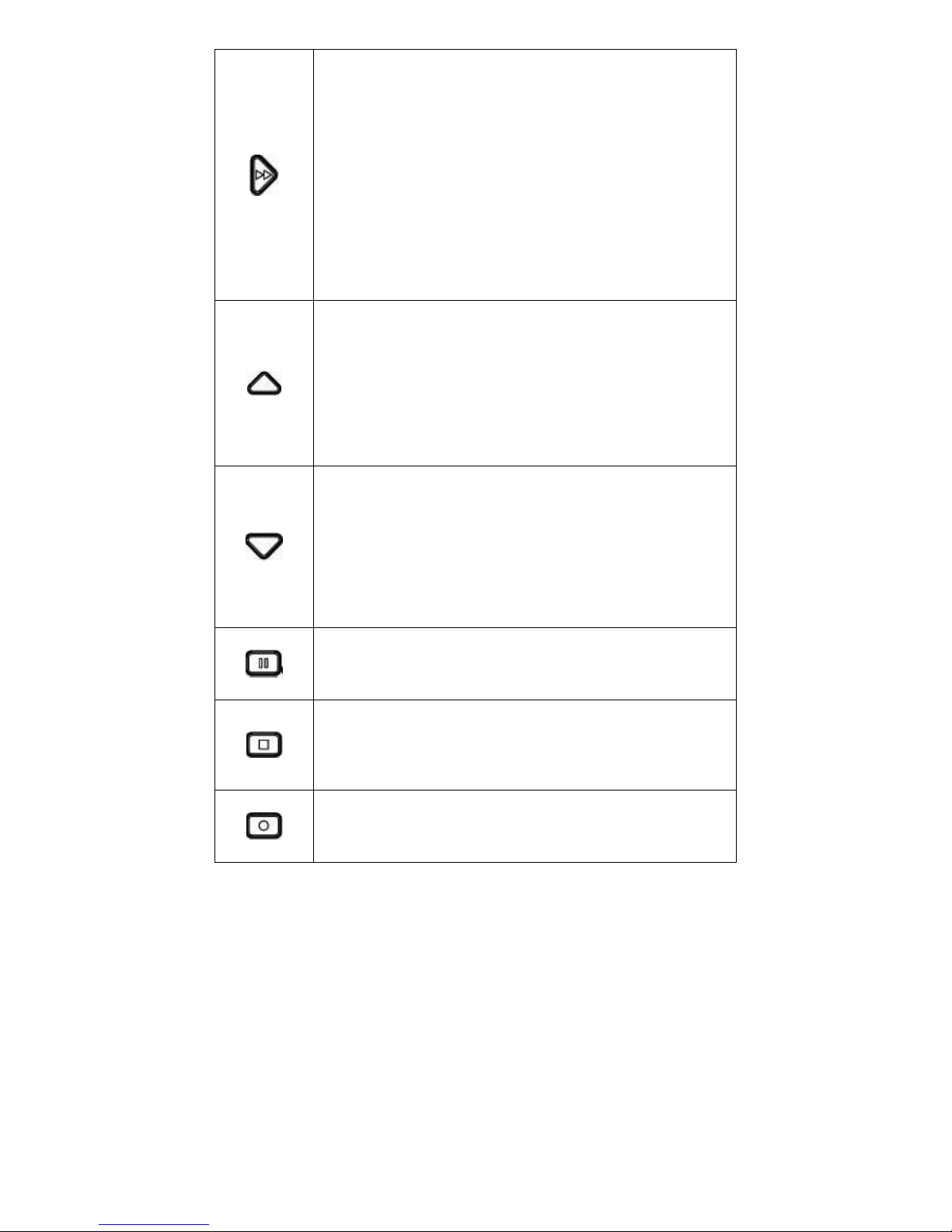
Right Arrow Key (mode dependant):
During Playback Mode: Right Arrow Key adjusts fast
forward playback speed from 0.5X to 90x.
From Pause Mode: Right Arrow Key steps one frame at
a time
From Record Mode: Right Arrow Key enables One Touch
Zoom feature. Press and release will zoom to predefined
setting and hold for 15 sec.
Press and hold will manually control zoom in.
Up Arrow Key (mode dependant):
Playback Mode: During standard 1x playback, Up
Arrow Key Cycles forward through the channels
Live & Record Modes: In Live Video / Record mode, the
Up Arrow Key cycles among channel views 1-4 and quad
view. Quad view only appears when the resolution on all 4
channels is the same.
Down Arrow Key (mode dependant):
Playback Mode: During standard 1x playback, Down
Arrow Key cycles backward through the channels.
Live & Record Modes: In Live Video / Record mode, the
Down Arrow Key cycles among channel views 1-4 and
quad view. Quad view only appears when the resolution
on all 4 channels is the same.
Pause Button:
The Pause Button allows pausing of playback video and
resume play of video.
Stop Button:
The Stop Button stops the currently operation as displayed
on the video output. If all playback features are operating
the first press stops the Movie or recording Playback, the
second stops Recording.
Record Button:
The Record Button begins recording on all enabled
channels

8
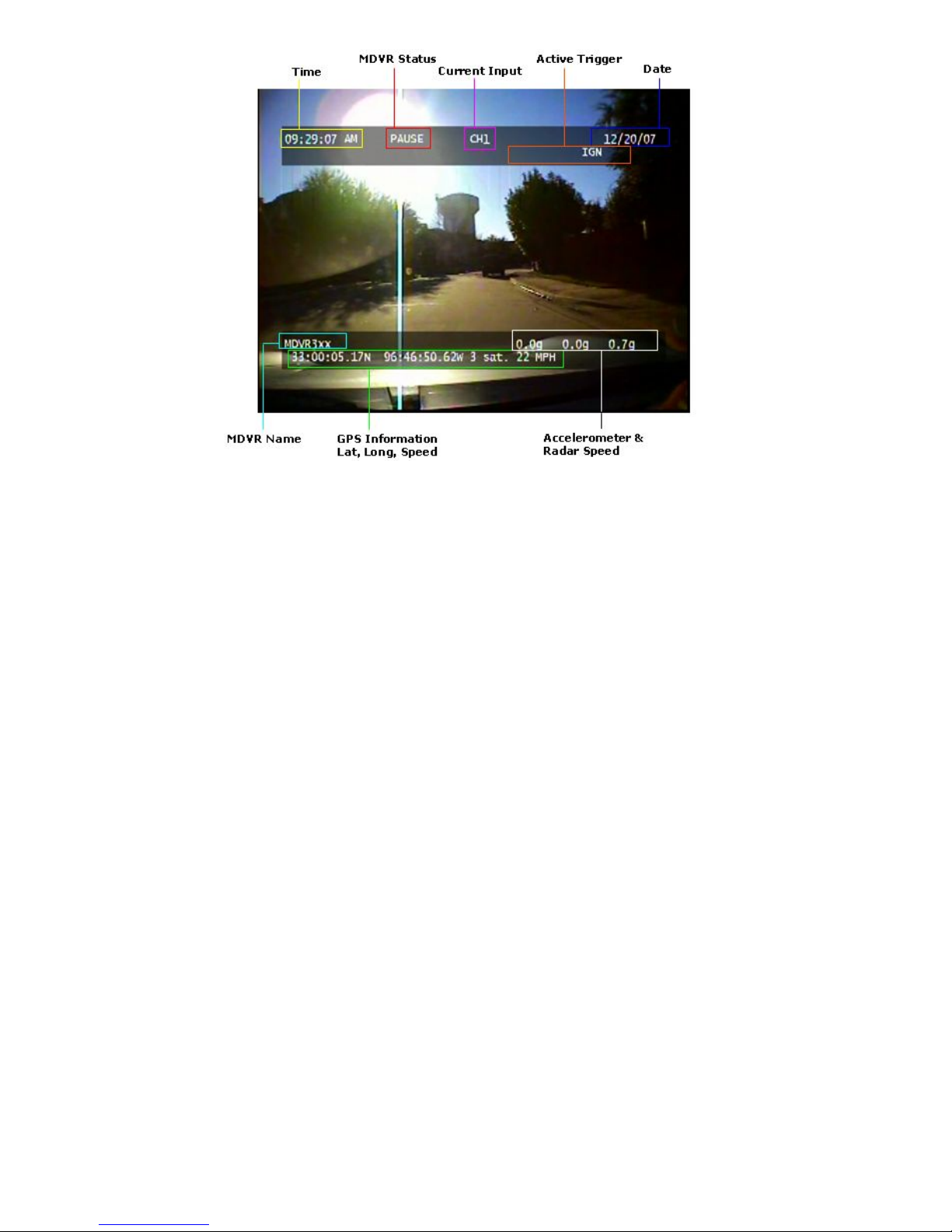
BASIC ON SCREEN DISPLAY
The Display shown in Figure 7 is the basic Display for the Record, Live
View and Playback Modes of operation. The video is recorded without
these overlays, but the data shown is attached to each video frame as
meta data for extraction by the video player software.
Time & Date:
This time and date is either entered manually and kept current with by
the MDVR or is acquired and synchronized by the GPS unit if the option
is selected.
Trigger Inputs:
There are 7 user selectable trigger inputs with a 4 character symbol.
MDVR Status:
Displays the status of the MDVR; includes idle, record, playback,
playback speed, and pause.
MDVR Name:
This is the 14 character field to identify car, officer and MDVR unit.
GPS Information:
This included Latitude, Longitude and current vehicle speed
Note: vehicle speed from radar is used instead of GPS when available.
Remaining Record Time (displayed in STOP record mode only):
This is the remaining storage time left on the Hard Drive in units of
hours:minutes.
9
Figure 1 - On Screen Display (OSD)

10
SYSTEM STARTUP FEATURES
At power up and any media insertion the MDVR searches the hard
drive first, then the SD card(s), if present for a folder named
“SYSTEM”. The first SYSTEM folder found will be used as the
startup folder and its contents processed. The following features
are available via the SYSTEM folder.
INSTALLING SYSTEM UPGRADES
Software / Firmware updates are distributed in files with a *.dvr
extension. Mount either the removable hard drive or optional SD
card to a PC. Find or create at the root of that media a SYSTEM
folder. Copy the *.dvr file into the SYSTEM folder. Remove this
media from the PC and install it into the MDVR and then power
cycle the MDVR. The MDVR will automatically install the *.dvr file.
Placing multiple *.dvr files in a SYSTEM folder will have
unpredictable results and is not advised. The system will not reinstall the same upgrade so there is not a problem to leave the
*.dvr file on the media until the next upgrade opportunity.
Figure 2 - Firmware Upgrade

11
NOTE: During upgrade the Power switch is disabled. Do not
remove power during this time.
Automatic Movie Playback
The SYSTEM folder is searched for an “SY S TEM-content-001.avi“
file. This movie file will be played to the system video outputs
during normal operation. Stopping the movie playback will revert
the system to its default of showing the real time camera video.
Accessing the configuration menus will cause the menus to
appear on-screen but the movie will continue to play. Once the
movie is stopped it can only be restarted by power cycling the
system or re-inserting the media.
Normally it is recommended that this file should be loaded to the
SYSTEM directory when the media is removed from the MDVR
and connected to the PC or USB Hard Drive Carrier, however it
can be replaced using the FTP interface. In this case the new file
shall be named “new-content-001.avi”. After uploading this file,
another file named “new-content.ready” is placed in the same
directory. This file is used only as an indicator to the MDVR that
the uploaded file is ready to replace the existing file at the next
media insertion or power up, therefore it may be of zero length (it
is not read).
Use of the “new-content.ready” indicator file is useful when
uploading large .avi files to many MDVRs and there is a need to
activate them all at once. Since the “new-content.ready” file is very
small but movie files can be large and time consuming to upload,
many devices can have their replacement movie activated quickly,
especially if the FTP operations are scripted.
AUTOMATIC CONFIGURATION SCRIPT
The MDVR will execute all commands in a “setup.txt” script file.
The format of the script file is the same as the TELNET command
line. Any command you can enter via telnet can be put in the
script file.
One use for this feature is for the police market so the officer can
insert his SD card, or personal removable hard drive, and have
the name of the MDVR configured with to officer’s name or vehicle

12
ID. This information will appear in the metadata of the recorded
video.

13
MDVR MENU STRUCTURE
Press the SEARCH button and release. The Display shown in the Figure
below is the video search menu used for searching recorded video
filesets on the Hard Drive. The column on the left shows the days with
the column on the right showing time in that day. A pound symbol in the
right column signals that the recording was triggered by an event.
Figure 3 - Playback Menu
Video playback can be accessed at any time and is available
during recording without interrupting the current recording activity.

14
Main Menu Access:
1) Hold the SEARCH button for three to four seconds.
2) To scroll menu use UP and DOWN ARROW buttons.
3) To make menu selections use the RIGHT ARROW as “Enter”.
4) To return to a previous screen use the SEARCH button as
“Back”.
The Display shown in Figure 10 below is the main unit menu. From this
menu access to all other setup screens is possible.
Figure 4 - Main Menu

15
Figure 5 - System Menu
System Menu
(Figure 11)
Field
Action
Default
OSD
Enables or disables on screen display
Enable
Record
Mode
Toggles between continuous
recording or stop trigger recording
Stop
Units
Modifies unit system between Metric
or English.
English
GP Out 1
Mode
Configurable Open Collector output.
Notification of state of one of the
MDVR attributes. See details below.
Record
GP Out 2
Mode
Configurable Open Collector output.
Notification of state of one of the
MDVR attributes. See details below.
Power
Time Setup
Brings up the Time Setup menu.
Password
Setup
Brings up the Password Setup Menu
Advanced
Setup
Brings up the Advanced Setup menu
General purpose trigger outputs are configurable to indicate the
following conditions:
RECORD
unit is recording

16
PLAY
unit is in playback mode
POWER
unit is powered on
TRIGGER_ACTIVE
any of the X triggers are in the active state
DISK_FULL
Recording is in STOP mode, disk is full so
recording has stopped
T1-T7
activated when the specified trigger has voltage
applied (HIGH state)
USER_CONTROL
User has sent the trigger command to the MDVR
using telnet protocol
ACCEL
acceleration has exceeded normal limits as
defined in GPS Setup Menu
SPEED
speed has exceeded normal limits as defined in
GPS Setup Menu
MDVR PASSWORD MENUS
Figure – Password setup
A password can be used to control access to some or all configuration
functions. A display must be connected to the video output of the MDVR
to display the password prompt. When the user attempts to use a
protected feature the display will prompt for the password. The front
panel keys are used to select each character and enter the password
before access is granted.
The password field consists of 6 characters with a default password of:
“123456”. After this sequence is entered, the system allows access for
30 minutes (or after cycle power) before the password is enabled again.
The unit supports 4 levels of password protection with the ability to

17
enable any or all levels. These are defined below:
o All Keys: Any key press required a password.
o Power-off: The Power button requires a password.
o Playback: Video playback requires a password.
o Menu: Access to the menus requires a password.
Figure 6 - Time Setup
Time Setup Menu
(Figure 12)
Field
Action
Default
Date
System date (assuming GPS
date is OFF)
Today’s Date
Time
System time. If GPS is enabled
edits to this field will be
overwritten by the system when
it synchronizes with the GPS
(approximately once a minute)
Today’s Time
Timezone
Offset from GPS reported time.
Set to zero if no GPS
0
Note: -6 for Central
US time
Daylight
Savings
Automatic adjustment for
daylight savings time change.
ON
Format
Clock format for 12 or 24 hour
display.
12HR

18
Figure 7 - Advanced Setup Menu
Advanced Setup Menu
(Figure 13)
Field
Action
Default
Restore Defaults
Restores the factory default
settings.
Disk to Erase
Sets the target disk for the Erase
and Format operations
C:
Erase Media
Permanently deletes all recorded
data except SYSTEM directory
from the selected media.
Note: Not normally needed unless
correcting an error.
Format Media
Permanently deletes all recorded
data from the selected media and
installs DVR filesystem.
Note: Not normally needed unless
correcting an error. Use in
response to “No Disk” error when
disk is installed (system can not
read disk)
Faster than Erase Media
Network Setup
Opens the Network Setup menu.

19
Figure 8 - Network Setup Menu
Network Setup
(Figure 14)
Field
Action
Default
IP Address
Manually entered IP address.
Note: Requires power cycle to take
effect
Subnet Mask
Manually entered subnet mask.
Note: Requires power cycle to take
effect
FTP Username
Manually entered username for FTP
transactions
USER
FTP Password
Manually entered password for FTP
transactions
PASS
Save
After configuration, the save option
must be selected.

20
Figure 9 - Titles Setup Menu
Title Setup
(Figure 15)
Field
Action
Default
System
Name
14 character name (ie. Car # /
Officer / Other)
MDVR3xx
Trigger x
4 character trigger name
1 – 7

21
Triggers can be configured to the following actions. All triggers are
recorded in the meta-data.
o MARK: Starts a recording if not already recording and labels the
recording as an event in the file name.
o START [RECORD]: Starts a recording and will record until the
stop button is pushed on the front of the unit or the storage
media is full. The MDVR has pre-event recording and will record
from a short time before the event.
o STOP [RECORD]: Stops a recording if the unit is recording.
o RECORD: Starts a recording and records while the trigger is
active. Stops recording when the trigger is not active.
o DISPLAY: Will display the trigger event on the OSD and will
record the trigger in the file meta-data.
Figure 10 - Trigger Setup Menu
Trigger Setup
(Figure 16)
Field
Action
Default
Trigger 1-7
Enter a name for the trigger
event / Enter if the trigger is
active high or low / Select the
action for the trigger event
(MARK, START, STOP,
RECORD while active,
DISPLAY)
Trigger-x / Active H /
No Action
Ignition
Setup
Displays settings for ignition
options.

22
Ignition Setup
(Figure 17)
Field
Action
Default
Record
Control
Enables or disables immediate
recording at unit startup. When
enabled the Record Start and
Stop delays are activated.
Enable
Record Start
Delay
Delay time before record start
following ignition ON.
0Min
Record Stop
Delay
Delay time before record stop
following ignition OFF.
0 Min
Power Off
Delay
Delay time after ignition OFF and
Recording stopped with no
activity before unit power off.
Note: setting this field to minus 1
(‘-1’) keeps unit on indefinitely
until power removed. Caution:
This can run a battery down.
10 Min
The ignition trigger has special handling inside the MDVR intended to
support motor vehicle applications where recording can start and stop
automatically. Enabling the Record Control field in the Ignition Setup
turns ON the automatic recording features. The following table details
how specific events are handled.
Record
Control
Setting
Ignition
State of
Manual
Power
button
System Behavior
DISABLE
ON
Turning ON
Turn ON
DISABLE
OFF
Turning ON
Turn ON, but turn OFF automatically after
idle for Power OFF Delay
DISABLE
OFF
Turning OFF
Turn OFF immediately (under manual
control)
DISABLE
Turning OFF
ON
Turn OFF after Power OFF Delay
DISABLE
ON
Turning OFF
Turn OFF immediately (under manual
control)
DISABLE
ON
ON
Turn OFF after Power OFF Delay
DISABLE
Turning ON
OFF
Turn ON (for completely manual operation,
disconnect ignition trigger)

23
ENABLE
ON
Turning OFF
Ignition priority so ignore manual request.
Stay ON
ENABLE
ON
Turning ON
Turn ON, can only happen if power was
lost.
ENABLE
OFF
Turning ON
Turn ON, but turn OFF automatically after
idle for Power OFF Delay
ENABLE
Turning OFF
ON
Turn OFF after Record Stop Delay if
recording, else turn OFF immediately
ENABLE
OFF
Turning OFF
Turn OFF immediately (under manual
control)
ENABLE
ON
ON
Stay on indefinitely (no Power OFF Delay)
ENABLE
Turning ON
OFF
Turn ON, start recording after Record Start
Delay
Figure 11 - Ignition Setup Menu

24
MDVR IGNITION / POWER ON CONNECTION
MDVR Ignition Trigger Power ON Control
The MDVR features an auto power on and begin record function on the
“ignition trigger”. When this trigger goes high, the DVR will turn on and
then, after the user selectable power on delay, begin recording..
MDVR Ignition Trigger Power OFF Control
After the ignition trigger goes low (car turned off), the DVR will turn off if it
was idle. If it is recording it will continue recording for the Record Stop
Delay and then turn off. Note: the Power Off Delay setting has no effect
on ignition controlled power offs.
MDVR Power Button Control (while Ignition Trigger OFF)
If the ignition trigger is low (car off), the power is controlled only by the
Power Button. When the button is pressed, the unit will turn on until the
button is pressed again or several minutes of inactivity have passed (as
set by the Power Off Delay). The Power Off Delay setting is an inactivity
timer that is intended to help prevent draining the vehicle battery when
the MDVR is used while the ignition is OFF.

25
Figure 12 - Comm. Setup Menu
Comm. X Setup
(Figure 18)
Field
Action
Default
Baud Rate
Selects Baud Transfer Rate
• 9600, 4800, or 38400
9600
Parity
Selects none, even, or odd parity.
None
Data Bits
Selects number of data bits.
8
Stop Bits
Selects number of stop bits.
1
Protocol
Protocol selection (zoom cameras):
• None
• Visca (Sony)
• Costar
Costar
One Touch
Zoom
Zoom control feature, in
percentage.
100 PCT

26
Camera x Setup
(Figure 19)
Field
Action
Default
Frame Rate
Control setting for frame rate. Choices
are: DISABLED,1, 5, 7.5,
10,15,30,CUSTOM*
Note: DISABLED is not available on
channel 1. System must record on at
least channel 1.
30 fps
Image Size
Selects the image resolution:
D1 – 720 x 480
VGA – 640 x 480
QD1 – 360 x 204
QVGA – 320 x 240
320 x 240
Image
Quality
Image quality selection of HIGH,
MEDIUM HIGH, MEDIUM, MEDIUM
LOW, LOW, CUSTOM*. Lower image
quality provides longer record times due
to higher compression rates.
MEDIUM
Audio
Recording
Selects whether to record audio (ON), or
no audio (OFF).
ON
Audio
Volume
Volume control setting.
12dB
*CUSTOM – set via telnet command. See section on TELNET
COMMANDSl

27
Figure 13 - Camera Setup Menu
The GPS Setup Menu is only shown when a GPS device is installed.
The local time used by the product is calculated by adding the Time
Zone Offset to the GPS time. Usually GPS provides coordinated
universal time (UTC time). Set your offset from GPS time in the
Time Setup menu (under System Setup).
GPS Setup
(Figure 20)
Field
Action
Default
Use GPS
Selects whether to utilize the GPS
positioning data.
YES
Use GPS
Time
Selects whether to utilize the GPS
time and date settings.
YES
GPS Data
Format
Selects GPS display format:
DDD:MM:SS, DDD:MM.mm,
DDD.dddd
DDD:MM:SS
Calibrate
Accel
Resets current mounted orientation
to zero.

28
Figure 14 - GPS Setup Menu
Figure 15 - System Information
System Info
(Figure 21)
Field
Action
Default
Disk Size
Storage capacity of the record
media.
Percent
Used
Percentage of used space on the
record media.
Percent Free
Percentage of free space on the
record media.
Firmware
Version
Version of the installed firmware.
MAC
Address
Ethernet MAC address of the
unit. Unique for each unit.

29
REMOVABLE HARD DRIVE
The removable hard drive can be loaded with up to 2 IDE 2.5” hard drives
or 1 SATA 2.5” hard drive. The DVR treats all hard drive memory as a
large storage area but the Advanced Setup menu offers disk specific
operations (erase, format). Configuring the removable drive with 2 drives
provides some redundancy but since data is stored in one file during
capture, the loss of a drive will remove half the onboard storage and data.
FILE STRUCTURE
In the root directory of the Hard Drive, the DVR will create a new
subdirectory for each day of recording. The subdirectory is named as
follows:
Mmm.dd.yyyy
• Mmm - 3 letter month abbreviation, e.g. Jan, Feb, Mar,…Dec
• dd - day (01 - 31)
• yyyy - 4 digit year, e.g. 2006
Each subdirectory will contain a fileset of one or more AVI files that are
grouped by file name. In order to minimize the effect of a forced
shutdown where any open files may be lost the DVR periodically closes
the file record and opens a new one. In addition, to help navigate records
for events the DVR closes the current file and opens a new one each time
an event is triggered, so triggered events can be found and viewed easily.
The file naming convention is as follows:
Mmm.dd.yyyy_hh.mm.ss [#] –[seq].avi
• Mmm.dd.yyyy - same as directory name
• hh.mm.ss - 24 hour time in hours, minutes, and seconds when
this fileset began recording. This is the local time, so if a GPS is
used to obtain UTC time, this filename will be the UTC plus the
timezone offset.
• ‘#’ – Marks a file that was initiated due to an ‘event’ of interest as
defined by the trigger condition of MARK..
• -[seq] – sequence number of file in the fileset. Sequence
numbers start with ‘-001’ and increment from there, however if the
DVR is in continuous record mode, where the oldest files are
overwritten, sequence number ‘-001’ may be deleted. Therefore
the lowest sequence number is the beginning of the available
acquisition.
• avi - AVI file extension
EXAMPLE:
Found in the C\ Mar.12.2008 directory:

30
Mar.12.2008-17.36.48-001.avi
Record button manually
pressed
Mar.12.2008-17.36.48#-002.avi
Trigger event occurred
Mar.12.2008-17.36.48#-003.avi
Another event occurred
Mar.12.2008-17.36.48-004.avi
No even occurred, DVR created
next file in sequence
automatically

31
FTP COMMANDS
The DVR supports only the following FTP commands in a DOS window:
cd
Changes Directory.
dir
Directory Listing.
ls
List directory.
get
Gets a file from the DVR.
put
Writes a file to DVR.
rmdir
Removed a directory from the
DVR.
Because of these limits, FTP does not work within Internet Explorer. It
does work from the DOS command-line FTP.
'rmdir' must be used with caution. The DVR does not ensure that the
directory is empty prior to deleting the directory. Deleting a directory does
not automatically delete the files in that directory. The application (or
user) of FTP must ensure that the directory is empty prior to removing a
directory, or else space on the Hard Drive will become unavailable for
use.

32
TELNET COMMANDS
The MDVR3xx accepts ASCII commands via an Ethernet Telnet session. A telnet
session may be used to control the MDVR remotely. All features of the keypad
can be controlled via telnet commands and some extended features are only
accessible via telnet.
cd
Change Directory.
date [mm/dd/yy]
Set/query date.
display [Channel]
Set/query audio/video output. CHANNEL
may be '1', '2', '3', '4', or 'quad')
exit
Exits Telnet.
format /x
Formats disk x, where x = c,d,e,….
keylock [on | off]
Set/query front panel keylock.
ls [-l]
Get short/long directory listing.
media
Query media or disk status.
mute [on | off]
Set/query audio output mute.
pwd
Print working directory.
play date [Mmm.dd.yyyy]
Set/query playback date.
play time [hh.mm.ss]
Set/query playback time.
play position [sss]
Set/query playback position (in seconds)
play rate [rateFactor]
Set/query playback rate (-90 <=
rateFactor <= 90)
play [on | off]
Set/query playback state
record [on | off]
Set/query record state
restore-config
Restore default DVR parameters
save-config
Save DVR parameters
set [param] [value]
Set/query DVR parameters (see below)
shutdown
Turn off the DVR

33
time [hh:mm:ss]
Set/query time
Trigger [1 | 2] [on | off]
Turns on/off indicated trigger (GPOUT)
version
Query DVR version string
Examples for PLAY command
1) Query available dates, then select one
play date
100 Sep.01.2007
100 Sep.11.2007
200 OK
play date Sep.11.2007
200 OK
2) Query available times, then select one
play time
100 14:12:32
100 15:47:05
200 OK
play time 14:12:32
200 OK
3) Query current playback information for selected date/time
- query returns the following parameters:
State, Date, Time, Length, Position
. State : "On" or "Off"
. Date : as shown in examples above
. Time : as shown in examples above
. Length : length of video clip in seconds
. Position : current playback position in seconds
play
200 Off, Sep.11.2007, 14:12:32, 637, 0
4) Begin playback, seek 30 seconds into the video, fast forward
(30x)

34
play on
play position 30
play rate 30
5) Pause video, then stop playback
play rate 0
play off
TELNET PARAMETER SPECIFICATION
Parameters are supplied to the SET command to provide extended configuration
setup. Sending the command SET [param] with no value will read and display the
current value. Sending SET [param] [value] changes the setting on the DVR.
The following parameter names are case sensitive and must be typed exactly as
shown (including “dots” and “dashes”.
camera-1.uSecsPerFrame
Defines recording frame rate by specifying the number of
microseconds to wait between each recorded frame.
A value of 0 indicates that this camera is not to be recorded.
Value must be a multiple of 33,333.
Maximum value is 299,997,000 (299.9 secs or 5 minutes).
camera-1.bitRate
Specifies recording bit rate in bits/seconds.
Must be a multiple of 500,000 (0.5 Mbit/sec).
Minimum value is 500,000 (0.5 Mbit/sec).
Maximum value is 20,000,000 (20 Mbits/sec)
camera-1.resolution
ASCII string which specifies image resolution (or frame size).
"D1" - 720x480
"VGA" - 640x480
"QD1 - 360x240 (Quarter-D1)
"QVGA - 320x240 (Quarter-VGA)
camera-1.audio
Specifies whether audio is to be recorded on this channel.
"OFF" - do not record audio for this channel
"ON" - record audio for this channel
camera-2
Same as camera-1, except settings are for camera input #2.
camera-3
Same as camera-1, except settings are for camera input #3.
camera-4
Same as camera-1, except settings are for camera input #4.

35
dvr.version
Read-only parameter, contains DVR firmware version number
dvr.macAddr
Read-only parameter, contains DVR MAC address
dvr.temperature.min
Read-only parameter, contains minimum operating temperature of the DVR at
which point the hard-disk is turned off to prevent damage.
dvr.temperature.max
Read-only parameter, contains maximum operating temperature of the DVR at
which point the hard-disk is turned off to prevent damage.
file.maxSize
Defines maximum file size for the DVR to generate. Once this size is reached, the
DVR will continue recording in a new file.
Must be a multiple of 1,048,576 (1 MByte).
Minimum value is 512 MByte.
Maximum value is 1 GByte.
file.maxTime
Defines maximum amount of time to record in a single file. Once this time is
reached, the DVR will continue recording in a new file.
maxSize and maxTime are used at the same time. When either limit is reached a
new file is created.
Minimum value is 60 seconds.
Maximum value is 600 seconds (10 minutes).
Must be a multiple of 60 seconds.
net.ipAddr
IP address of DVR.
Default value is 192.168.2.110 (this will change in the future).
net.subnetMask
Ethernet subnet mask.
Default value is 255.255.255.0
net.userName
Network login username (used by FTP).
net.password
Network login password (used by FTP).
net.ftpTimeout
Timeout in seconds for FTP to close in inactive connection.
Minimum value is 60 (1 minute).
Maximum value is 600 (10 minutes).
Increment is 60.
net.telnetTimeout

36
Timeout in seconds for Telnet to close in inactive connection.
Minimum value is 60 (1 minute).
Maximum value is 3600 (60 minutes).
Increment is 60.
system.title1
Up to 32 ASCII characters to identify system
system.title2
Up to 32 ASCII characters to identify system
system.title3
Up to 32 ASCII characters to identify system
uart-1.device
Selects external device which is connected to serial port #1.
"Costar" - indicates Costar camera is attached
"None" - indicates serial port is unused.
uart-1.baudRate
Specifies serial port baud rate.
“4800”
"9600"
"38400"
uart-1.numDataBits
Specifies number of data bits. Must be 5, 6, 7, 8, or 9.
uart-1.numStopBits
Specifies number of stop bits. Must be 1 or 2 (1.5 is not supported).
uart-1.parity
Specifies serial port parity
"none"
"odd"
"even"
uart-2
Same as uart-1, except settings are for serial port 2

37
ETHERNET STREAMING PROTOCOL
OVERVIEW
The DVR streams audio/video data on TCP port 1234. This port is used for
audio/video only. No control information is sent via this port.
All control will be performed using standard commands via the Telnet interface on
TCP port 23.
The DVR allows multiple clients to stream audio/video if desired. This is limited to
a maximum of 8 external connections (RS-232, Telnet, FTP, or Streaming).
Video data is sent every frame. Audio data is buffered and sent five times a
second, or every 200 milliseconds.
BANDWIDTH THROTTLING
If Ethernet bandwidth (or client resources) become congested, the DVR will
throttle bandwidth by dropping video frames. No audio will be dropped. Dropped
video frames are marked in the data stream by sending zero length video frames
so that the client can keep track of dropped frames to ensure audio/video
synchronization.
DATA STREAM FORMAT
The data stream consists of audio/video blocks. Each block begins with an 8 byte
header which contains an audio/video stream identifier and a block length. This
header is the standard AVI data chunk header and is defined as follows:
chunkId: 32-bit audio/video stream identifier
chunkSize: 32-bit integer indicating number of data bytes following this header
The stream identifiers are (in little endian format):
Video Stream #1: 0x63643030 ("00dc")
Audio Stream #1: 0x62773130 ("01wb")
Video Stream #2: 0x63643230 ("02dc")
Audio Stream #2: 0x62773330 ("03wb")
Video Stream #3: 0x63643430 ("04dc")
Audio Stream #3: 0x62773530 ("05wb")
Video Stream #4: 0x63643630 ("06dc")
Audio Stream #4: 0x62773730 ("07wb")
If any video frames are dropped by the DVR, they are indicated by receiving a
video chunk with a size of 0 bytes.

38
AUDIO/VIDEO SYNCHRONIZATION
Upon receiving a connection to TCP port 1234, the DVR streaming task will
synchronize itself to the audio/video stream and begin streaming of data as
follows:
While buffering 200 ms of audio data, send video frames.
The client should buffer these video frames.
Send 200 milliseconds of audio data to client.
The client can now begin playback (or may wish to buffer another 200 ms chunk of
audio/video data).

39
HARDWARE INSTALLATION
The MDVR features dual captured nuts in both sides of the unit allowing
for multiple installation options. Utilizing standard brackets, the MDVR
can be installed as a bottom mount as shown in Figure 1 and as a DIN
mount as shown in Figure 2. Care must be taken to not obstruct the
ventilation holes in the bottom of the unit to ensure proper operation over
the specified temperature range.
Figure 16 – MDVR Bottom Mounting Diagram

40
Figure 17 - MDVR Front Mounting Diagram

41
MDVR CONNECTION
The MDVR features a variety of connection points for various accessories
as shown in Figure 3 below:
Figure 18 - MDVR Connection Guide
The external connections feature:
• Quad camera audio and video input
• Video / Audio monitor output
Standard TCP/IP Ethernet connection featuring:
• Built-in File Transfer Protocol (FTP) server
Main Molex Connector featuring:
• Direct automotive power connection. The MDVR features
an internal reset capable fuse.
• 7 trigger inputs and 1 ignition.
• 2 configurable Open Collector trigger outputs.

42
BACK PANEL CONNECTION DETAIL
Audio / Video Connector (J3)
Molex 5613409000 Pins
Pin #
Function
1,3,5,7,9,11,13,
15,17,19,21,23
Ground
2
Audio Out
4
Audio Out
6
Video Out
8
Ignition input indication
10
Input 1 – Audio In
12
Input 1 – Video In
14
Input 2 – Audio In
16
Input 2 – Video In
18
Input 3 – Audio In
20
Input 3 – Video In
22
Input 4 – Audio In
24
Input 4 – Video In
25
-12V Camera 1 Power
26
+12V Camera 1 Power
27
-12V Camera 2 Power
28
+12V Camera 2 Power
29
-12V Camera 3 Power
30
+12V Camera 3 Power
31
-12V Camera 4 Power
32
+12V Camera 4 Power
33
Main Power (-)
34
Main Power (+)
35
Main Power (-)
36
Main Power (+)
Trigger / RS232 Connector (J4)
Molex 51353-2400 Connector
Molex 5613409000 Pins
Pin #
Function
1,3,9,
15,21,22
Ground
2
Trigger 1
4
Trigger 2
6
Trigger 3
8
Trigger 4
10
Trigger 5
12
Trigger 6
14
Trigger 7
16
GP Open Collector 1 output
18
GP Open Collector 2 output
20
12V Audio Power
5
Serial kypd Transmit (future)
7
Serial kypd Receive (future)
11
Serial 1 Transmit (Radar Gun)
13
Serial 1 Receive (Radar Gun)
17
Serial 2 Transmit (Zoom camera)
19
Serial 2 Receive (Zoom camera)
23
Ignition input indication
24
Unused

43
EQUIPMENT SPECIFICATIONS
Specifications
Recording
Capabilities
Four NTSC video camera inputs up to 30 fps with
synchronized audio and meta-data.
Meta-Data Capture
for Each Frame
Input voltage, unit temperature, 14 character unit
name, panic button events, all triggers status and
names, operating mode & version numbers, time
& date, optional GPS lat/long/speed.
Compression
Motion JPEG compression w/ 5 selectable
compression ratios.
Resolution:
Selectable 720 x 480, 640 x 480, 360 x 240, or
320 x 240.
Frame Rate:
Selectable 30 FPS to 1/1 FPS.
Video File Format
8 channel AVI (4 video, 4 audio) playable with
Player application (Windows Media Player only
plays first video/audio channel)
Archive Media
Type:
2.5” EIDE Mobile Hard Drive support up to 120GB.
Typical Record
Time
40 GB Hard Drive: 46 hrs typ up to 66 hrs.
80 GB Hard Drive: 92 hrs typ up to 132 hrs.
120 GB Hard Drive: 130 hrs typ up to 200 hrs.
Power Supply
Input Rating
Standard automotive power range; 8 – 24 Volts.
On Power
Consumption w/o
Cameras
< 470 mA
Off Power
Consumption
< 10 mA
12V Camera Power
Output Max
12V @ 1 Amp regulated switched power outputs.
External Trigger
inputs:
7 input triggers plus the ignition trigger.
External signal
outputs:
2 Open Collector output.
Transient
Protection
2500 Watts for 10ms
Operating
Temperature:
5 C ~ 55 C (41 F ~ 131 F) ambient temperature.
Operating
Vibration:
Linear 5-300 Hz, 1.0G (0 to peak)
Unit Weight:
2 kg (4.5 lbs)

44
Unit Size:
7 in (178 mm) x 2 in (51 mm) x 8 in (203 mm);
1DIN Mountable
 Loading...