

FleetLynx AMG1000ALx-VCM Installation Manual

Advanced Mobile Gateway AMG1000
Light Duty/Passenger Vehicle
Installation Guide (AMG1000ALx-VCM)
1.0 Safety & Regulatory Information
Important safety and regulatory information on the AMG unit may be found on on page 15
this installation guide.
CAUTION: Be sure to thoroughly review the safety and regulatory information before installing and
activating the AMG unit.
2.0 Kit Contents
There are four AMG aftermarket kits for light-duty/passenger vehicles:
• AMG1000BLx-VCM kits include the “Backpack Antenna” and will be used in the
majority of cases, where both the base unit and the antenna are to be installed in
the vehicle interior. Instructions for the AMG1000BLx-VCM kit installation are not
included here, but are available online.
• AMG1000BOx-VCM kits include the “Backpack Antenna” and will be used in the
majority of cases, where both the base unit and the antenna are to be installed in
the vehicle interior. Instructions for the AMG1000BOx-VCM kit installation are not
included here, but are available online.
• AMG1000AOx-VCM kits include the “External Antenna” and should be used when it
is necessary to install the antenna on the cab exterior or if specifically requested by
the “fleet” customer. Instructions for the AMG1000AOx-VCM kit installation are not
included here, but are available online.
• AMG1000ALx-VCM kits include the “External Antenna” and should be used when it
is necessary to install the antenna on the vehicle exterior or if specifically requested
by the “fleet” customer.
This is the installation guide for the AMG1000ALx-VCM kit as shown in Figure 1.
AMG1000ALx-VCM Light Duty/Passenger Vehicle Kit Installation Guide 1
r04
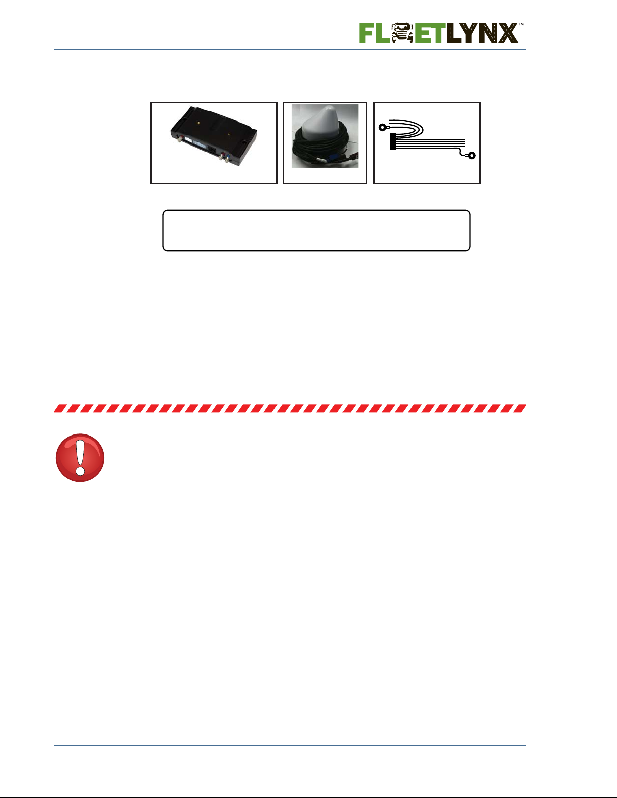
AMG1022L
Wiring Harness for Light
Duty/Passenger Vehicles
AMG1000ALx-VCM kit contents:
AMG1020x
Advanced Mobile Gateway
AMG1021A
External Aerodynamic
Antenna
x=U if equipment is to be operated in the USAwhere:
x=C if equipment is to be operated in Canada
Figure 1: AMG1000ALx-VCM Light Duty/Passenger Vehicle Kit
3.0 Recommended Tools
The following tools are recommended for the installation:
• Phillips and Square Drive screwdrivers – to unscrew the dashboard
• Carpenter knife – to separate wires C&D from covering over both wires (if needed)
• Crimp Tool – to attach add-a-circuit fuse accessory
• Zipties – to secure loose wiring and perhaps the AMG itself
IMPORTANT – PLEASE COMPLETE THE
FOLLOWING TASKS BEFORE
INSTALLATION
Turn the truck on and check for existing lamps, warning
lights, or anything out of the ordinary:
Investigate issues as needed before beginning the install – this thorough pre-install exam
helps troubleshoot issues should any arise after installation. Please record any lamps or
warnings on the installation form.
2 AMG1000ALx-VCM Light Duty/Passenger Vehicle Kit Installation Guide

Activate the AMG:
0.
5.)43.
1234567890
!-'5
AMG1020U
AMG Serial Number
Bottom of AMG Unit
AMG Bar Code Label (Close Up)
0.
5.)43.
1234567890
!-'5
AMG1020U
MODEL: AMG1020U
FCC ID: OPP-AMG1020X
IC ID: 2943A-AMG1020
(877
) 955-3122
Il est important que le numéro de série
de cet appareil soit associé au numéro
du camion qui recevra cet appareil.
It is important that the
UNIT S/N
is
associated with the
Truck #
that
will receive this unit.
Please call
to activate
Veuillez appeler
pour activer
Step 1: Obtain Required Information
The following information is required to activate an AMG unit:
• AMG Serial Number – see Figure 2 for location of this information
• Fleet Name – the name of the fleet the vehicle belongs to
• Truck Number – the number the fleet uses to identify the vehicle
• Dealer Code – the code for the dealership where the FleetLynx unit was
purchased from
• VIN – the Vehicle Identification Number for the vehicle in which the AMG unit will be
installed
• Odometer – the vehicle odometer reading from the dash
Step 2: Call 1-877-955-3122
Call this number once the information from Step 1 is obtained. A customer service agent will
then activate the unit. It will usually take a few minutes to complete.
AMG1000ALx-VCM Light Duty/Passenger Vehicle Kit Installation Guide 3
Figure 2: AMG Serial Number
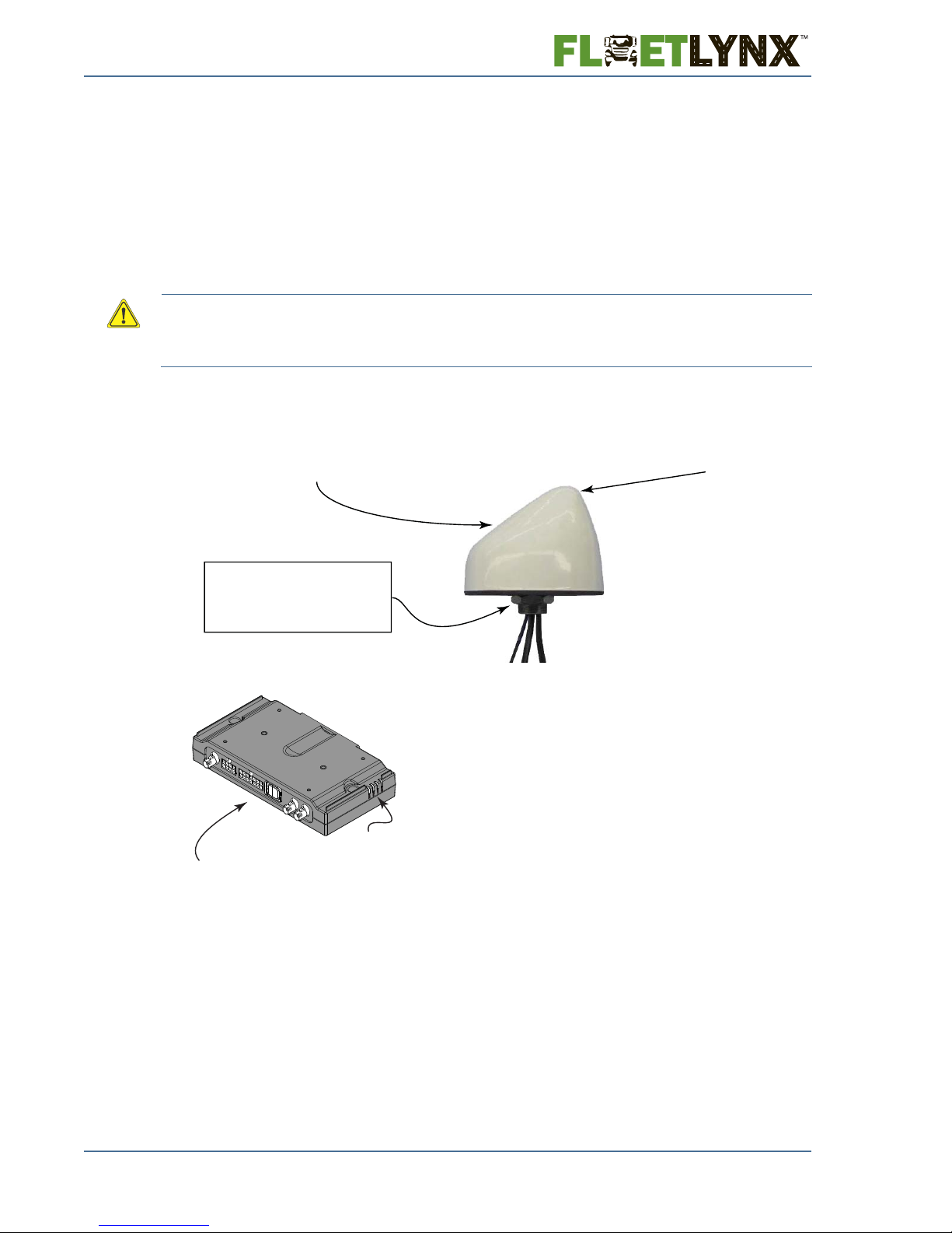
External antenna mounting (cab exterior):
AMG BASE UNIT
ORIENTATION
NOT CRITICAL
The mounting location
should provide access
to the cable connections
on the AMG base unit.
The mounting
location should
allow the status
LEDs to be
visible.
Mount this end facing up;
unobstructed by metal objects
Mount this side towards front of vehicle
AMG base unit mounting (cab interior):
Note: If the underside of the
threaded base bolt is exposed
to the environment, a sealant
is required.
Identify the best location for installation:
Before the wiring harness, AMG base unit and antenna are installed, it is strongly
recommended that the vehicle cab is inspected for potential installation locations and an
installation plan is devised. Keep the following information in mind when locating a suitable
install location and plan:
1) The AMG base unit may not be installed any further than 9 feet away from the vehicle’ s
interior fuse panel.
2) The external antenna (included in AMG1000ALx-VCM kits only) may be installed up to
15 feet away from the AMG base unit.
WARNING! The external antenna must only be used with the supplied cable [type=RF-195,
length=15 feet (4.5 meters), minimum attenuation=2.25dB] or similar cable with minimum
attenuation of 2.25dB. This is necessary to limit the antenna gain to no more than 3dBi in order to
comply with FCC part 24.
3) Antenna reception is critical for effective AMG operation, therefore the antenna must not
be obstructed by metal objects. Optimal antenna orientation is shown in Figure 3.
The external aerodynamic antenna mounts outside the vehicle cab (generally on the roof).
For optimal reception, the antenna should be mounted on a horizontal metal surface as
4 AMG1000ALx-VCM Light Duty/Passenger Vehicle Kit Installation Guide
shown in Figure 3 but not be obstructed by surrounding metal objects. The mounting
surface should be no thicker than ¼”. To mount the antenna, a hole ¾” in diameter must be
drilled or punched into the surface. For roof mounts, remove any material on the underside
of the cab before creating the hole. In order to secure the antenna mounting, it is necessary
to also have access to the underside of the hole (normally inside the cab). The gasket
attached to the underside of the antenna acts as a moisture seal which prevents moisture
from entering the vehicle.
Figure 3: Optimal Unit Orientation

To attach the antenna, first remove the nut. Feed the cables through the hole, seat the
antenna on the surface, and then reattach the nut. The nut should be tight (5 ft. lbs. max) in
order to properly seal the gasket. Tighten the nut with a wrench. For unforeseen conditions,
silicone may be added around the base of the antenna. Finally, feed the cables to the AMG
inside the cab.
Note: If the underside of the threaded base bolt is exposed to the environment, a sealant is required.
A good install location will be one that:
• Is not visible to the driver
• Will allow the technician to be able to see all four LEDs on the unit.
• Allows easy access to the GPS, CDMA, and GSM connections on the unit
• Enables the AMG base unit to be secured via screws, such that the screws are not
visible to the driver.
PROCEED WITH INSTALLATION ONLY AFTER
THE ABOVE TASKS HAVE BEEN COMPLETED
AMG1000ALx-VCM Light Duty/Passenger Vehicle Kit Installation Guide 5
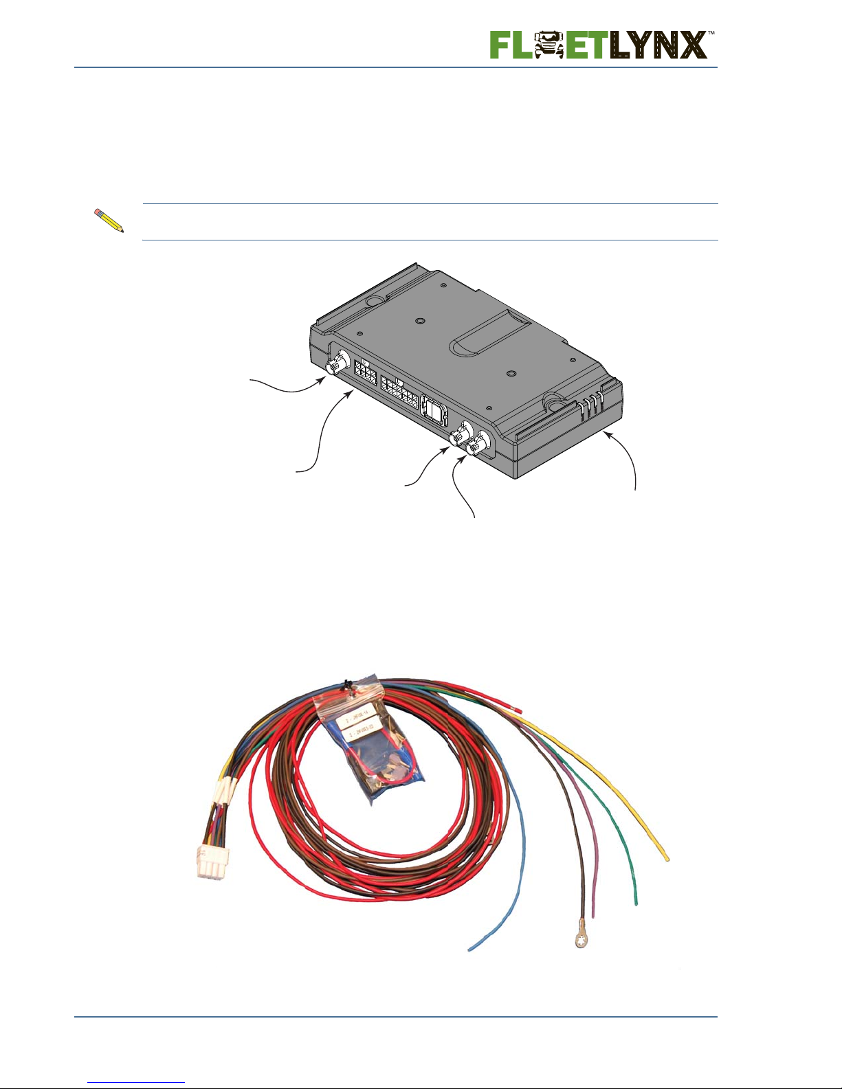
GSM
Cellular
Antenna
Connector
8 Pin
MOLEX
Connector
CDMA
Cellular
Antenna
Connector
GPS
Antenna
Connector
Unit
Status
LEDs
4.0 Connecting the AMG
4.1 AMG Base Unit Connections
The AMG base unit connectors are shown in Figure 4.
Note: There are two cellular antenna connections, one is for GSM and the other is for CDMA. Be sure
to check connections made to the AMG unit thoroughly.
4.2 Wiring Harness for Light Duty Vehicles
The wiring harness for Light Duty/Passenger Vehicles comes with two add-a-circuit devices.
6 AMG1000ALx-VCM Light Duty/Passenger Vehicle Kit Installation Guide
Figure 5: Wiring Harness for Light Duty/Passenger Vehicles
Figure 4: AMG Base Unit Connectors
 Loading...