

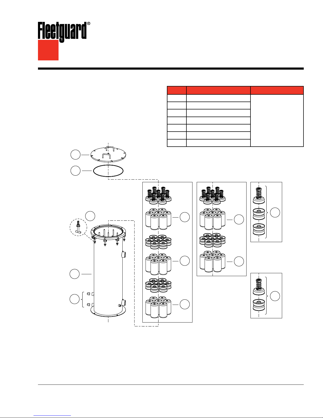
Winslow® – Liquid Fuel Filters
A
B
E
E
Internal
Component Kit
for 95830A
F
Internal
Component Kit
for 95730A
Internal Components
for 95730A
Internal Components
for 95830A
E
E
E
F
C
D
G
T-Bolt Kit
(includes
Washer,
Nut and
T-Bolt)
Standard Design Type 2
Service Instructions
Parts List
Part Description Part Number
Cover
A
O-Ring
B
Housing
C
Plugs
D
Filter Elements
E
Internal Component Kit
F
T-Bolt Kit
G
See Ordering Information
on Page 5
CAUTION: These instructions are intended for use by professional mechanics who are trained in the proper E
use of power and hand tools, using appropriate safety precautions (including eye protection).
page 2
Vent Plug
“Dirty Oil”
Drain Plug
Introduction
Winslow® filter elements must be changed
periodically to assure the high level of filtering
efficiencies required. We recommend that the
elements be changed when the pressure differential
across the filter reaches the maximum allowable
pressure drop as recommended by the engine
manufacturer. Excessive pressure differential across
the elements could result in reduced flow.
Winslow Fuel Filters are designed to be mounted
on the pressure side of a low pressure (< 75 PSI
(517.1 kPa)) fuel pump, however they can be
mounted on the suction side of a low pressure pump
if sized properly. Housing restriction for suction side
applications must be less than 1 PSID (6.9 kPa).
Pump specifications regarding inlet restriction
should be followed and supersede other general
recommendations.
To determine the correct pressure differential:
Note the pressure drop between the filter inlet •
and outlet when clean elements are installed
and the system is up to normal operating flow,
temperature, and pressure.
Periodically check the gradual increase of •
the filter differential pressure as the filter
accumulates hours of operating service.
If no engine specification is known or given, filters
should be changed out at 5-7 PSID (34.5-48.3 kPa)
above initial differential pressure. Initial differential
pressure should be 2-3 PSID (13.8-20.7 kPa)(an
initial differential pressure less than 3 PSID
(20.7 kPa) is acceptable, but a smaller filter could
probably be used).
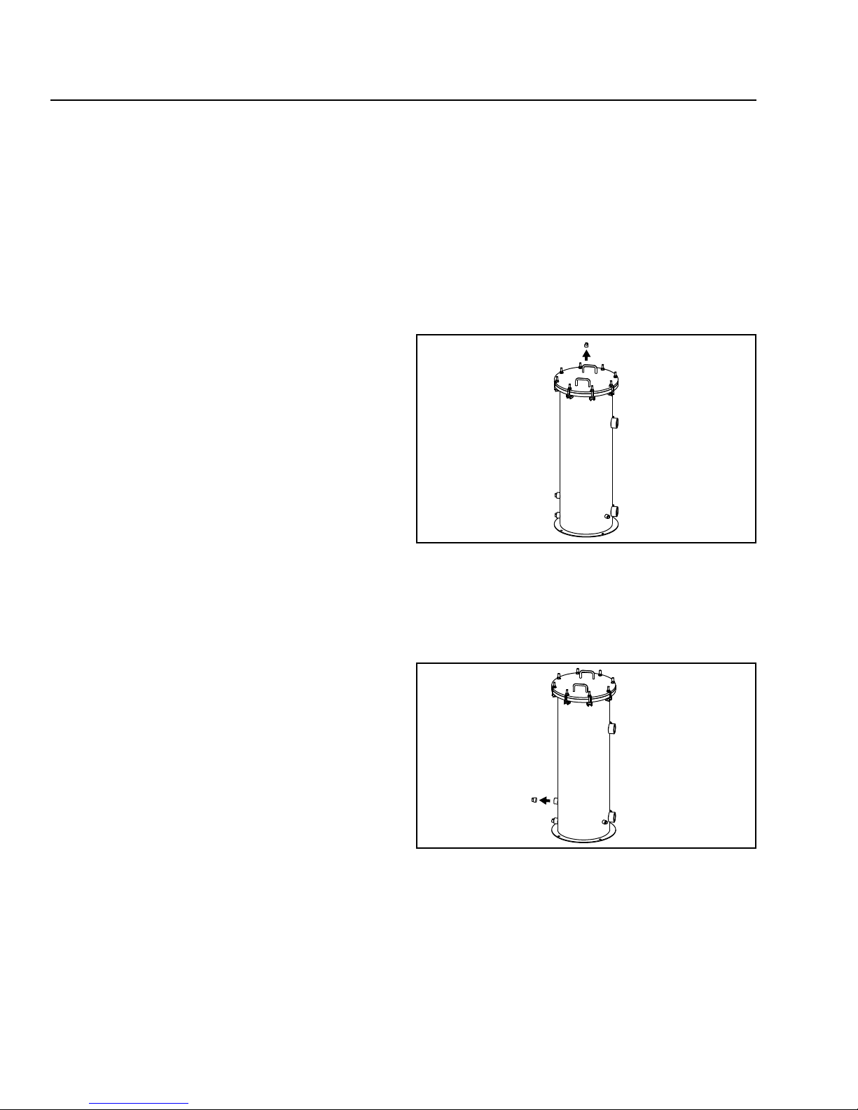
Servicing the Filter
Removing the Filter Elements
Shut off the flow to the filter. Isolate the filter, if 1.
possible, by closing the main upstream valve and
then the main downstream valve.
Shut off electrical power to any accessories 2.
attached to the vessel.
Remove the air vent plug to equalize the 3.
pressure in the tank.
Figure 1 – Removing the Air Vent Plug
Remove the “dirty oil” drain plug (upper plug) and 4.
completely drain the filter chamber.
E
CAUTION Fluid may be hot!
The filter design includes a sludge and water sump
section. A drain is provided at the bottom of the
sump for use when the elements require changing.
Figure 2 – Removing the “Dirty Oil” Drain Plug

page 3
Loosen Nuts
Swing T-Bolts
Lift
Cover
Straight
Up
Element
Support
Posts
Element
Support
Posts
Dirty
Elements
Seal Cups
Dirty
Elements
Internal
Components
(vary according
to housing)
Loosen the nuts on the cover until the T-bolts are 5.
free to swing out of position.
Figure 3 – Freeing the Cover
Lift the cover STRAIGHT UP.6.
E
CAUTION To prevent damage to the cover
gasket and the sealing surfaces,
DO NOT SLIDE THE COVER OFF.
Loosen the hex nuts on the element support 8.
posts to free the internal components.
Figure 5 – Freeing the Internal Components
Loosen and remove the internal components, 9.
including the dirty elements (components vary
according to housing – see page 1). Pull the
elements straight up to remove. Dispose of the
elements in an environmentally responsible
manner, according to state and/or federal (EPA)
recommendations.
Figure 4 – Lifting the Cover Off
Place the cover UPSIDE DOWN on a clean work 7.
surface. Be careful not to nick or scratch the
bottom edge of the sealing surface.
Figure 6 – Removing the Internal Components
E
CAUTION To prevent damage to your engine
or equipment, do not allow dirt
to fall through the opening of the
element support post and into the
clean outlet area.

page 4
Element
Support
Post
Spent
Elements
Seal Cups
Spent
Elements
Internal
Components
(vary according
to housing)
O-Ring
Cover Seal
Flange
Groove
Replace
Cover
Straight
Down
Reassembling the Filter
Reinstall the internal components, including the 10.
new elements. Note the direction of the arrow
on each element and insert the proper end into
the housing first. If seal cups are included as
part of the internal components, they must be
reinstalled, as well.
Replace the O-ring cover seal. (If necessary, 12.
as long as there are no permanent surface
deformations, swelling, nicks, and cracks
present, the seal can be reused.)
Figure 9 – Replacing the O-Ring Cover Seal
Seat the O-ring cover seal into the flange groove.13.
Carefully replace the cover STRAIGHT DOWN 14.
and align the bolt slots in the cover flange with
the slots in the housing flange.
Figure 7 – Reinstalling the Internal Components
Replace the hex nuts onto the element support 11.
posts and tighten until the threads bottom-out.
Figure 8 – Replacing the Hex Nuts
E
CAUTION To prevent damage to the cover
gasket and the sealing surfaces,
DO NOT SLIDE THE COVER ON.
Figure 10 – Replacing the Cover

page 5
Tighten Nuts
Swing T-Bolts
Dirty Oil
Drain Plug
Vent Plug
Swing the T-bolts into position and tighten all 15.
the nuts in a star pattern (similar to replacing lug
nuts on an automobile wheel) to assure a uniform
seal.
Figure 11 – Securing the Cover
When the vessel is full, reinstall the “dirty oil” 16.
drain plug.
Figure 12 – Reinstalling the “Dirty Oil” Drain Plug
Refill the filter manually or by slowly opening the 17.
main upstream valve.
When the vessel is full, reinstall the vent plug.18.
Figure 13 – Replacing the Vent Plug
Increase the pressure in the filter slowly. Inspect 19.
for leaks around the cover gasket area. If no
leaks are visible, increase to operating pressure.
Inspect for leaks again.20.
Reconnect electrical power to any accessories.21.
Slowly open the downstream valve, if applicable, 22.
placing the unit in service.
Read and record the pressure differential of the 23.
clean elements.
The filter is now operational.24.
Suggested Preventive Maintenance
Ordering Information
C
Housing*
95730A Q80660A Q79058 Q69009 82375A
95830A Q80660A Q79058 Q69009 82375A
* Designed for 75 lb/in2 (517.1 kPa) continuous operating conditions.
Table corresponds to Parts List on cover page.
A
Cover
B
O-Ring
D
Plugs
Every Filter Change – Replace the O-ring cover
seal.
Every 12 Months – Check all fittings for leaks.
E
Filter
Element
Number of
Elements
14
21
F
Internal
Component Kit
990441K 990449K
990442K 990449K
G
T-Bolt
Kit

page 6
2" NPT
Outlet
2" NPT
Intlet
Thermometer
Port
1/2" NPT
Dirty Oil
Drain
1" NPT
Clean Oil
Drain
1" NPT
All dimensions are in inches (millimeters)
Vent
3/4" NPT
A
B
19.3 (490.2)
Mounting Holes in Base
16 (406.4) Required for
Element Replacement
∅.562 (1.43)
(4X) on
18.00 (457.2)
Bolt Center
15.75 (400.1)
5.0
(127.0)
Replacement Filter Element
Part
Number
82375A
= 2 Full-Flow Lube Depth Element
b
5
Description
Filter Specification
Composed of a high flow cotton/wood media blend to provide b5 = 2 solid
contamination control.
Specifications
Housing Part
Number
95730A
95830A
* Flow rate based on #2 Diesel fuel with a maximum viscosity of 4.63 mm2/s. For residual and heavy fuel blends, Contact
Cummins Filtration®.
Notes:
1. Designed for 75 lb/in
2. Initial assembly differential pressure should not exceed 3 PSID (20.7 kPa) on the pressure side (downstream) of the pump.
3. Change element after initial differential pressure increases 3-4 PSID (20.7-27.6 kPa), depending on engine age and operating
oil pressures. A maintenance professional should make the appropriate application decision.
4. Terminal assembly differential pressure should not exceed 7 PSID (48.3 kPa).
Specifications subject to change without notice.
Flow Rate*
gal/min (L/min)
70 (265.0)
100 (378.5)
2
(517.1 kPa) continuous operating conditions.
Element
Number
82375A 82371A
82375A 82371A
Chemically
Treated Part
Number
Number of
Elements
14
21
Efficiency
(Particulate
Control)
b
= 2
5
b
= 2
5
Capacity
Capacity Exceeds
SAE Time
Constraints
Mounting/Dimensions
Housing*
Part
Number
95730A
95830A
* Designed for 75 lb/in2 (517.1 kPa) continuous operating conditions.
Overall
Height
in (mm)
47.0 (1193.8) 34.0 (863.6)
63.0 (1600.2) 50.0 (1270.0)
A
B
Inlet
Height
in (mm)
LT36077
©2008 Cummins Filtration
Printed in the U.S.A.
For more information, please visit us at cumminsfiltration.com
 Loading...