

Fleetguard Winslow 95250A, Winslow 95300A, Winslow 95200A, Winslow 95350A Service Instructions Manual

Winslow® – Liquid Fuel Filters
A
B
C
G
D
F
E
Vent
Plug (NPT)
Drain
Plug (NPT)
Internal
Component Kit
(varies according
to housing)
Standard Design Type 1
Service Instructions
Parts List
Part Description Part Number
Cover Assembly
A
O-Ring
B
Band Clamp
C
Housing
D
Filter Element
E
Internal Component Kit
F
See Ordering Information
on Page 5
CAUTION: These instructions are intended for use by professional mechanics who are trained in the proper E
use of power and hand tools, using appropriate safety precautions (including eye protection).
page 2
Vent Plug
Drain Plug
Band Clamp
Loosen
Nut
Cover Assembly
Introduction
Winslow® filter elements must be changed
periodically to assure the high level of filtering
efficiencies required. We recommend that the
elements be changed when the pressure differential
across the filter reaches the maximum allowable
pressure drop as recommended by the engine
manufacturer. Excessive pressure differential across
the elements could result in reduced flow.
Winslow Fuel Filters are designed to be mounted
on the pressure side of a low pressure (< 75 PSI
(517.1 kPa)) fuel pump, however they can be
mounted on the suction side of a low pressure pump
if sized properly. Housing restriction for suction side
applications must be less than 1 PSID (6.9 kPa).
Pump specifications regarding inlet restriction
should be followed and supersede other general
recommendations.
To determine the correct pressure differential:
Note the pressure drop between the filter inlet •
and outlet when clean elements are installed
and the system is up to normal operating flow,
temperature, and pressure.
Periodically check the gradual increase of •
the filter differential pressure as the filter
accumulates hours of operating service. When
(at normal operating conditions) the filter
differential increase is close to, or has arrived
at, the maximum differential pressure, the
elements must be changed.
If no engine specification is known or given, filters
should be changed out at 5-7 PSID (34.5-48.3 kPa)
above initial differential pressure. Initial differential
pressure should be 2-3 PSID (13.8-20.7 kPa)(an
initial differential pressure less than 2 PSID
(13.8 kPa) is acceptable, but a smaller filter could
probably be used).
Servicing the Filter
Removing the Filter Element
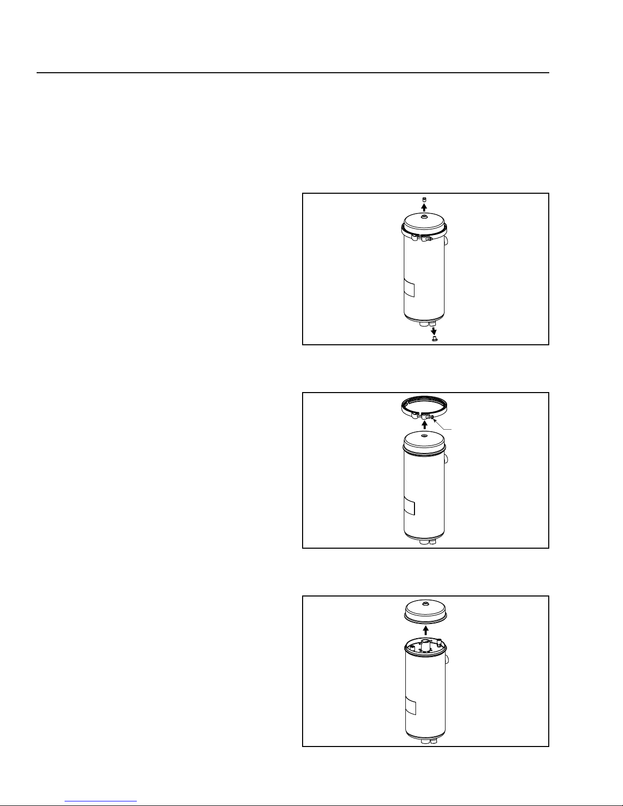
Remove the air vent plug and drain plug to drain 1.
the filter.
CAUTION Fluid may be hot!
E
Figure 1 – Removing the Air Vent and Drain Plugs
Loosen and remove the band clamp.2.
Figure 2 – Removing the Band Clamp
Remove the cover assembly.3.
Figure 3 – Removing the Cover Assembly
 Loading...