

Page 1
C
D
Winslow® Stationary Multiple
Element Design Fuel Coalescer
Service Instructions
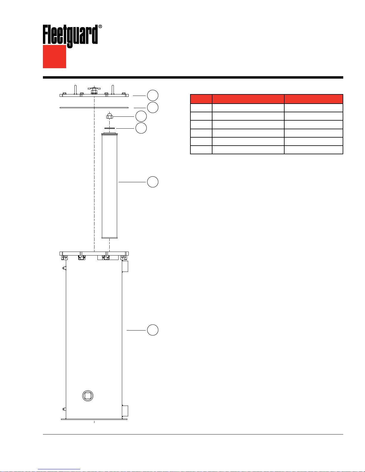
Parts List
A
B
E
Part Description Part Number
Cover Assembly
A
O-Ring
B
Seal Nut Assembly
C
Gasket
D
Filter Element
E
Housing
F
Q80660A
Q79058
Q53779
Q58878
88472N
91292N
E CAUTION: These instructions are intended for use by professional mechanics who are trained in the proper
use of power and hand tools, using appropriate safety precautions (including eye protection).
F
Page 2

page 2
Introduction
Unlike mechanical separators, the Winslow® Fuel
Filter/Coalescer can be installed on either the
pressure or suction side of the transfer or fuel pump.
Pressure Side
Pressure side installation is preferred because it
reduces fuel flow problems by eliminating air trapped
in the housing. With the first installation, or when the
unit has been serviced with an element change, the
cover vent valve is opened when the fuel pressure
is applied. Once the air in the unit has been purged
and the housing is filled, the valve should be closed.
The cover should be inspected for any possible fuel
leaks.
Suction Side
The fuel level from a storage source should be
higher than the housing in order for the inlet to
the filter assembly to have the necessary positive
pressure.
If a positive pressure is not available and the fuel
source is lower than the housing, the suction lift
or rise should not exceed 10' (3 m) to the housing
due to possible negative pressure into the housing
exceeding one atmosphere (14.7 lb/in
sea level. Also, line lengths must be kept as short as
possible.
It is also recommended that a check valve be
installed in the suction line close to the fuel supply
to prevent drain back and facilitate adding fuel to the
housing when elements have been changed. The
filters will have to be manually refilled after servicing.
Secure all fittings and cover bolts to prevent air
entrainment.
Existing filters in the system can be left in place,
whether up- or down-stream from the Coalescer.
Up-stream filters protect the Coalescer element
from large dirt particles that can eventually clog the
Coalescer. The Coalescer can work indefinitely,
removing water, if it doesn't become plugged
with dirt.
2
(1 bar)) at
If installed on the suction (vacuum) side, the housing
must be filled with fuel before operating the engine.
If installed on the pressure side, priming is not
necessary, but recommended.
If the application is for fuel transfer or a dispensing
pump where there is head pressure on the
Coalescer, a flow control valve must be installed at
the inlet port.
Because the Coalescer functions similarly
to a particulate or conventional filter, similar
troubleshooting procedures should be followed.
Servicing the Water Drain
1. Turn off the pump engine.
2. To remove water from the sump, loosen the drain
valve and allow the collected water to drain. (For
suction (vacuum) side installations, open the vent
to allow drainage.)
3. Tighten the valve as soon as fuel begins to drain.
(For suction (vacuum) side installations, close the
vent.)
Servicing the Elements
Elements should be changed when the pressure
drop across the element reaches 8-10 PSID
(55.2-69.0 kPa), or when the maximum pressure
differential the system can tolerate is reached,
providing the pressure differential is less than or
equal to 8-10 PSID (55.2-69.0 kPa).
If a pressure gauge is not used, elements should
be changed every six months or when engine
performance declines, indicating insufficient fuel
supply to the engine. A vacuum or differential
pressure gauge is strongly recommended.
Element change-out frequency is dependent on the
degree of solid and semi-solid contaminants present
in the fluid being conditioned. The amount of water
in the fuel does not affect the element change-out
frequency. Barring contamination, the Coalescer
would continue to coalesce and separate water from
fuel indefinitely.
Installation
To install on an engine or Cummins® Fuel Regen
System, cut into the fuel line and install with proper
fittings to connect to the Coalescer. Mount the
Coalescer with enough space to service the water
drain and for element replacement.
If an excessive amount of asphaltines or gums in
the fuel being conditioned is suspected, it would be
evidenced by relatively short change-out cycles.
Page 3

page 3
Determining the Pressure Differential
If the housing is equipped with an upstream and
downstream pressure gauge, or a differential
pressure gauge assembly, the pressure differential is
determined as follows:
1. Read and record the pressure shown on the
upstream (inlet) gauge. This reading is the high
indication.
2. Read and record the pressure shown on the
downstream (outlet) gauge. This reading is the
low indication.
3. Subtract the downstream pressure from the
upstream pressure. This difference is the back
pressure, or differential pressure caused by the
element.
Note: The upstream (inlet) pressure must always be
higher than the downstream (outlet) pressure.
If not, check the gauges for accuracy.
Note: The differential pressure gauge assembly is
equipped with a single gauge and indicates
the differential pressure in the housing
directly.
4. As the Coalescer accumulates hours of operating
service, the pressure difference between the
upstream and downstream pressure readings will
become higher. When the pressure differential
reaches the maximum allowable value of 8-10
PSID (55.2-69.0 kPa), the element must be
replaced in order to maintain high water removal
efficiency.
Replacing the Elements
1. Shut off the engine or fuel supply.
2. Close the inlet and outlet valves.
3. Loosen the vent valve.
4. Open the drain valve and drain the fuel and
water.
5. Release the cover plate clamping bolts and
remove the top cover plate, o-ring, seal nut and
gasket.
6. Check all gaskets for wear and replace as
needed.
7. Remove both the coalescing and the separator
elements.
8. Clean the canister by flushing it with #2 fuel oil.
9. Install the new separator element(s) first, making
certain they are centered.
10. Install the Coalescer element by lowering it inside
the separator element. Make certain the bottom
gasket contacts the end cap and seats properly.
11. Inspect the seal nut gasket and replace, if worn.
Lubricate and install the seal nut gasket.
12. Screw the seal nut down as far as possible by
hand, pushing the Coalescer element down with
one hand while tightening the seal nut with the
other.
13. Torque the seal nut to 10-12 ft-lbs (14-16 N·m) to
ensure a good seal.
14. Fill the canister with fuel.
15. Lubricate and replace the o-ring.
16. Replace the top cover plate.
17. Replace the cover plate clamping bolts and
torque evenly in a cross pattern to 70-80 ft-lbs
(95-109 N·m).
18. Tighten the vent valve.
19. Open the Inlet and outlet valves.
20. If it is a pressure side application, loosen the vent
valve to bleed off any air and completely fill the
canister with fuel. Close the vent valve when fuel
begins to ooze out.
21. Start the engine or fuel system.
22. Check for leaks or air locks.
Troubleshooting
1. Leaks - check for:
a. Worn gaskets
b. Improperly closed clamps
c. Open valves
d. Loose connections
2. No Fuel to the Engine (Air Locks)
a. Open the vent valve, remove the cover and
fill with fuel (see Step 19 above).
b. Check the inlet and outlet connections to
make sure they are not plugged.
Suggested Preventive Maintenance
Every Filter Change – Replace gaskets.
Every 12 Months – Check all fittings for leaks.
Page 4
page 4
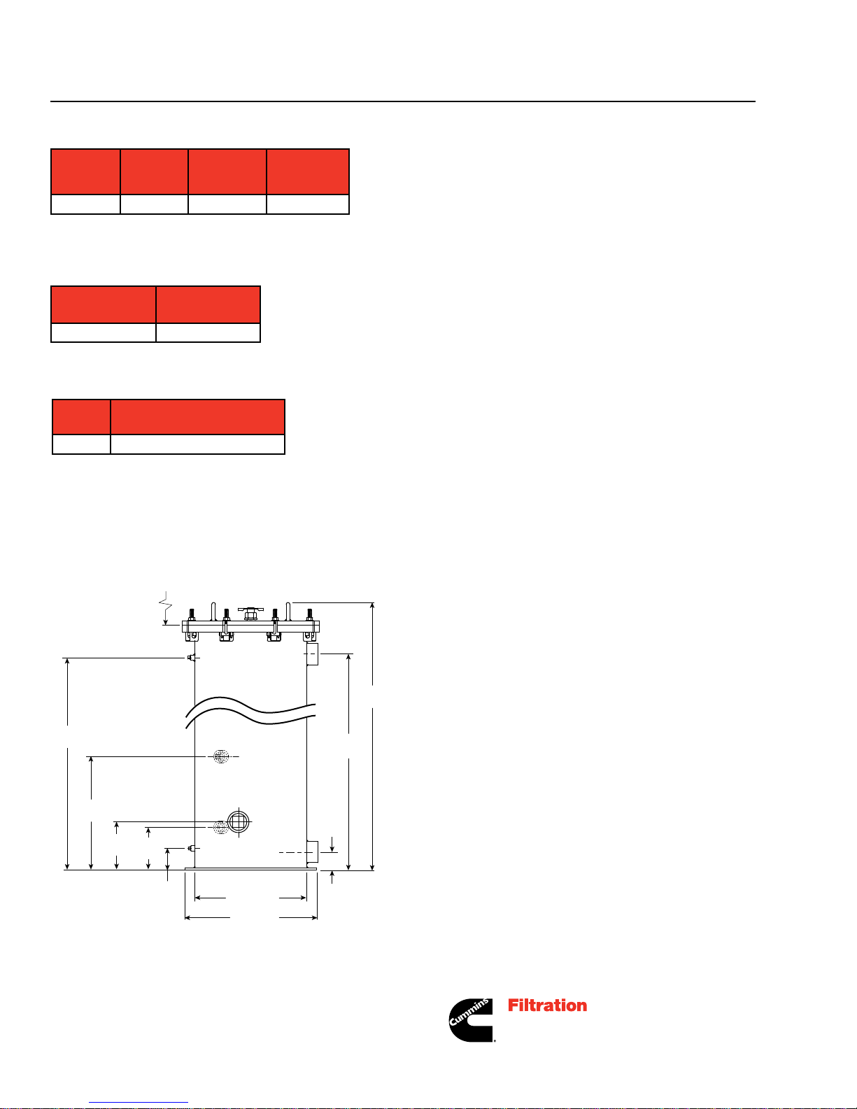
Specifications
Part
Number
91292N
* Clean filter at rated flow, based on #2 Diesel fuel.
** Change filter at 5 PSID (34.5 kPa) above initial pressure drop.
Design
Pressure
lb/in2 (kPa)
75 (517.1) 100 (378.5) 3.5 (11.9)
Flow Rate*
gal/min
(L/min)
Pressure
Drop**
in Hg (kPa)
Ordering Information
Housing Part
Number
Filter Element
91292N 88472N
Replacement Filter
Part
Number
88472N
Two-stage coalescing element
Description
Mounting/Dimensions
24 (609.6)
Required for
Element
Replacement
1/4" NPT
Pressure
Gauge Port
46.8
(1188.7)
39.00
(990.6)
13.00
(330.2)
6.75
(171.5)
6.00
(152.4)
3.00
(76.2)
1" NPT
Oil Drain
1" NPT
Water
Drain
1/4" NPT
Pressure
Gauge Port
15.75 (400.1)
19.3 (490.2)
2" NPT
Plug
2.50
(63.5)
39.50
(1003.3)
For more information, visit
cumminsfiltration.com
LT36200
©2011 Cummins Filtration Inc.
Printed in the U.S.A.
 Loading...