

Fleetguard REN Installation Instructions Manual
Liquid Level Switch Installation
LEVEL SWITCH
LISTED
U
L
®
TM
Instructions
CAUTION: These instructions are intended for use by professional mechanics who are trained in the
oper use of po
pr
F1302
wer and hand tools, using appropriate safety precautions (including eye protection).
page 2
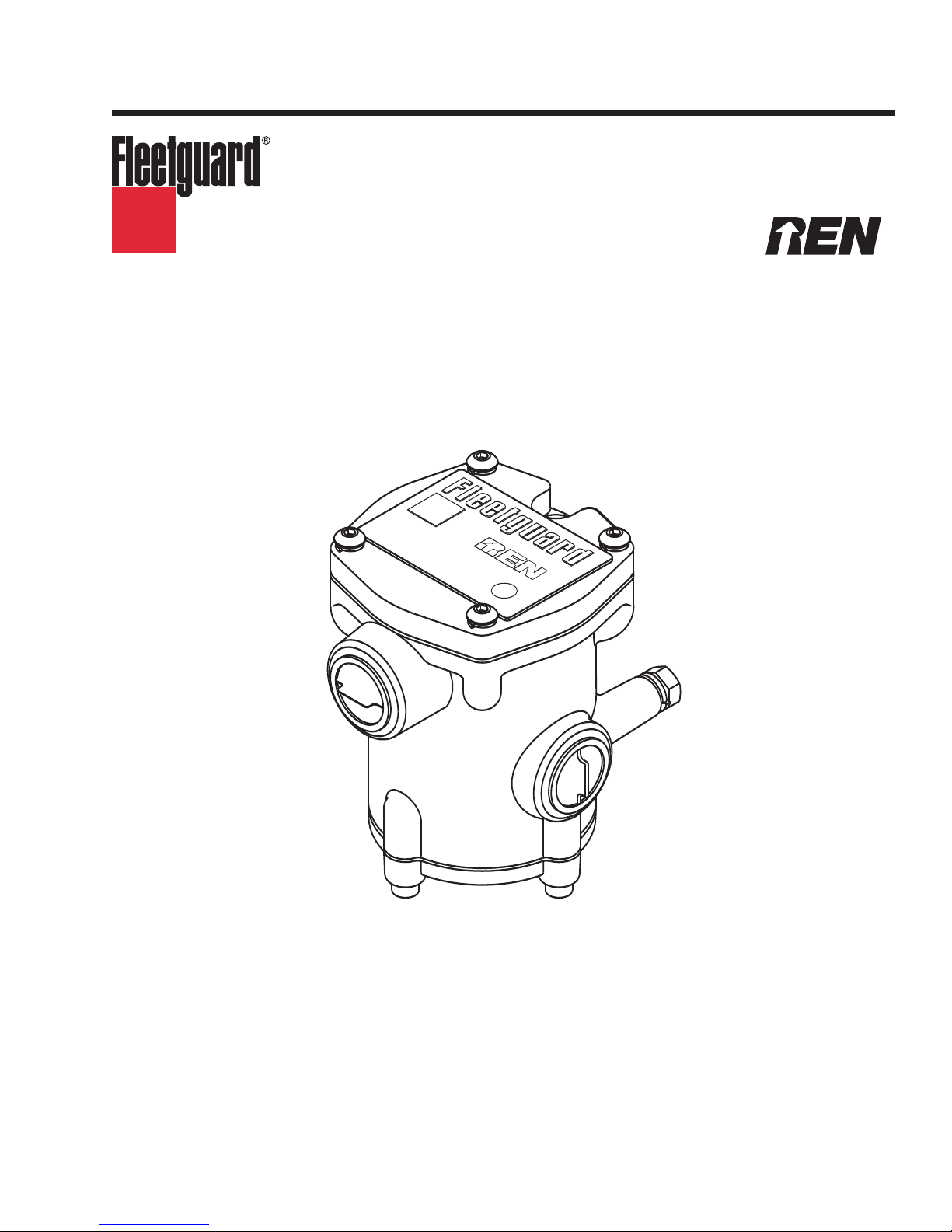
1.37
(34.80)
Liquid Level Switch
2.68
(68.07)
0.345
(8.76)
Switching Level
S
witching Level
Switching Level
L
iquid Tank
Stationary Engine
S
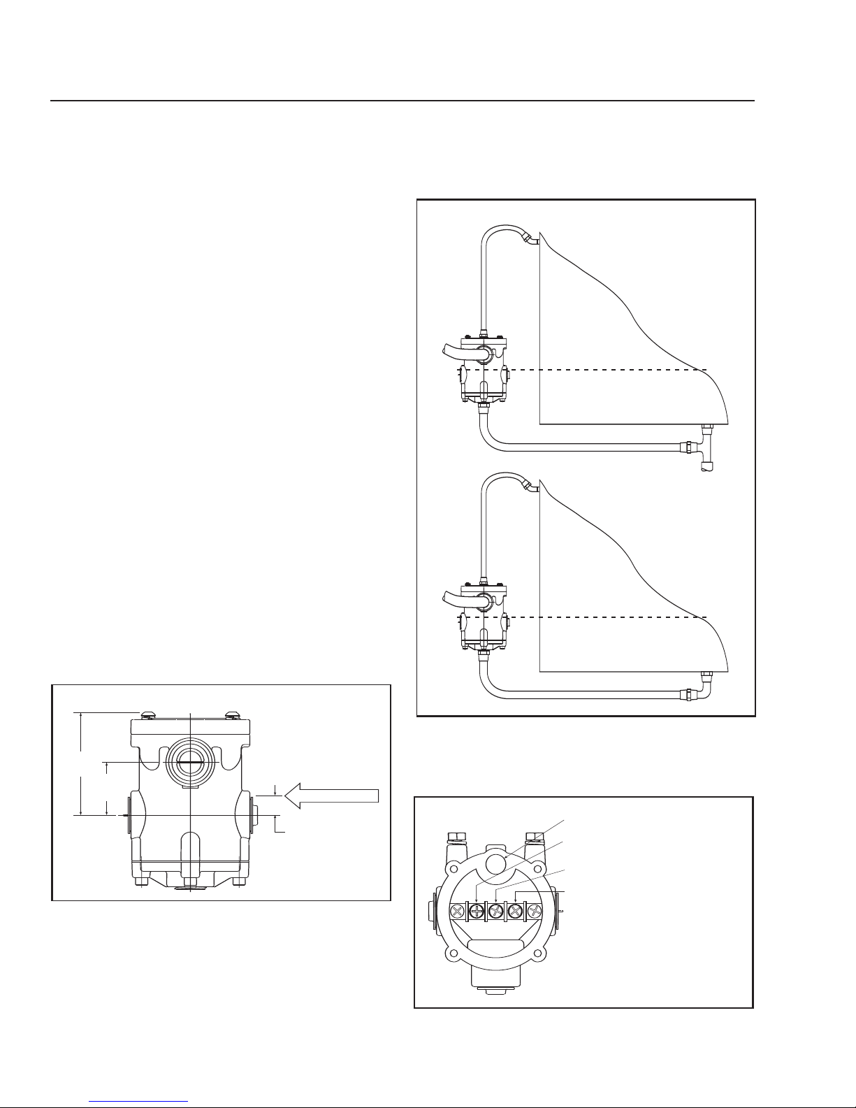
ensing Liquid Level
Top (Cover Removed)
N.C. C. N.O.
Top Liquid or Vent Connection 1/4" NPT
Closed on Low Terminal (N.O. Contact)
(Contacts open when fluid is above
switching level)
Common Electrical Terminal
Open on Low Terminal (N.C. Contact)
(Contacts closed when fluid is above
switching level)
Introduction
The REN™ Liquid Level Switch is used to indicate
levels of engine oil, hydraulic fluid and coolant
antifreeze. The switch can be used in most
applications where the level of a container, high or
low, or the absence of fluid in a line needs to be
detected. A single pole, double throw, magnetically
actuated switch is double sealed from explosive
environments through the use of two barriers; a
stainless steel housing and a hermetically sealed
glass switch housing. Four inlet / outlet ports and an
adjustable mounting pad allow great flexibility in
installation. Wiring is simple using the unit's
removable electrical housing cover.
Preinstallation Notes
• The Liquid Level Switch is designed for
stationary applications only.
• Use pipe or hose material appropriate to the
application for which it is being used.
• Route pipes and cables away from heat
sources and moving components.
Step 3 - Run a 3/8" (9.53 mm) ID minimum line from
the vent on the top of the Liquid Level Switch to the
container at or near the highest point on the
c
ontainer (see Figure 2).
Installing a Low Level or High
Level Switch in a Container
Step 1 - Mount the Liquid Level Switch to a solid
structure so that the switching level (see Figure 1) is
equal to the le
Step 2 - Run a 3/8" (9.53
the container at a level below the switch point to one
of the ports on the bottom of the Liquid Level Switch.
vel that the switch needs to activate.
Figure 1 - Switching Le
mm) ID minim
el
v
um line from
Figure 2 - Sensing Liquid Level
e the screws securing the electrical
Step 4 - Remo
v
housing cover and remove the cover (see Figure 3).
Figure 3 - Liquid Level Switch Terminals
F1302
 Loading...