

Fleetguard FH23916, FH23905, FH23901, FH23906, FH23913 Installation Instructions Manual
...Page 1
Industrial Pro® FH239 Series
Filter/Separator/Warmer
Installation Instructions
M
K
L
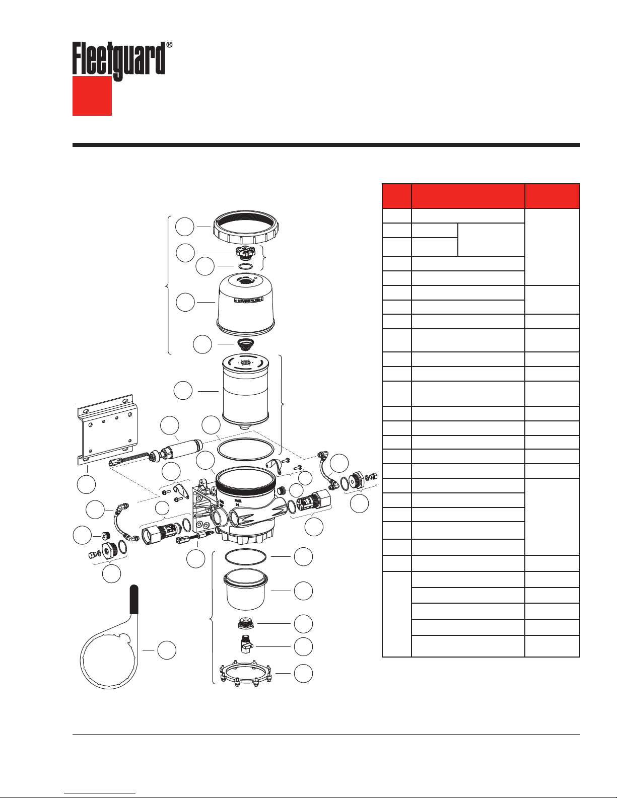
Industrial Pro® Single Short
Cover Assembly
O
H
N
W
A
B
D
F
I
Bottom
Assembly
P
Bowl
E
C
Part Description
A
Collar
B
Vent Cap
C
Vent Cap Assembly
Filter Element Assembly
(includes part C)
G
J
I
M
L
O
Q
R
S
T
U
O-Ring
D
Cover
E
Filter Spring
F
Filter Element (includes Part C)
G
O-Ring
H
Priming Pump (includes Isolators) SP1124
(2) Priming Pump Clamp and
I
(4) Screws
J
Industrial Pro
K
Bracket with Fasteners SP1131
(2) Priming Pump Hoses and
L
(4) Fittings
M
Plug 1/2" STOR SP1125
N
Bypass Check Valve SP1121
O Diagnostic Plug Fitting
P
Water-In-Fuel (WIF) Sensor SP1328
Q
Check Valve SP1120
R
O-Ring
S
Bottom Bowl
T
Drain Flange
U
Drain Valve
V
Bottom Bracket and Bolts (8)
W
Wrench SP1076
WIF Wiring Harness
WIF LED
Not
Electric Heater
Shown
Adapter Fitting, 3/4" to 1-1/4"
Adapter Fitting, 1-1/4" NPT
to M42 x 1.5
Vent Cap
Assembly
SP1053
®
Part
Number
Cover
Assembly
SP1127
FS53015
(includes Part C)
SP1133
See page 10
SP1128
SP1130
Bottom Bowl
Assembly
SP1134
3950729 S
3946670 S
See page 6
SP1135
3956561 S
E CAUTION: These instructions are intended for use by professional mechanics who are trained in the proper
use of power and hand tools, using appropriate safety precautions (including eye protection).
V
Page 2

page 2
Cover Assembly
J
N
Industrial Pro® Single Tall
A
M
K
P
B
C
D
E
F
G
H
I
O
Q
Bottom
Bowl
Assembly
Vent Cap Assembly
Filter Element Assembly
(includes part C)
L
M
S
T
U
Part Description
A
Collar
B
Vent Cap
C
O-Ring
D
Cover
E
Filter Spring
F
Filter Element (includes Part C)
G
O-Ring
H
Industrial Pro
I
Bracket with Fasteners SP1132
J Diagnostic Plug Fitting - Extended
K
Priming Pump (includes Isolators) SP1124
L
Check Valve - Extended SP1206
(2) Priming Pump Clamps and
M
(4) Screws
(2) Priming Pump Hoses and
N
(4) Fittings
O
Plug 1/2" STOR SP1125
P Bypass Check Valve
Q
Water-In-Fuel (WIF) Sensor SP1328
R Diagnostic Plug Fitting
S
O-Ring
T
N
O
R
Bottom Bowl
U
Drain Flange
V
Drain Valve
W
Bottom Bracket and Bolts (8)
X
Wrench SP1076
WIF Wiring Harness
WIF LED
Not
Electric Heater
Shown
Adapter Fitting, 3/4" to 1-1/4"
Adapter Fitting, 1-1/4" NPT
to M42 x 1.5
Vent Cap Assembly
SP1053
®
Part
Number
Cover Assembly
SP1127
FS53014
(includes Part C)
See page 10
SP1205
SP1133
SP1128
SP1121
SP1130
Bottom Bowl
and Drain Valve
Assembly
SP1134
3950729 S
3946670 S
See page 6
SP1135
3956561 S
X
V
W
Page 3
page 3
N
M
X
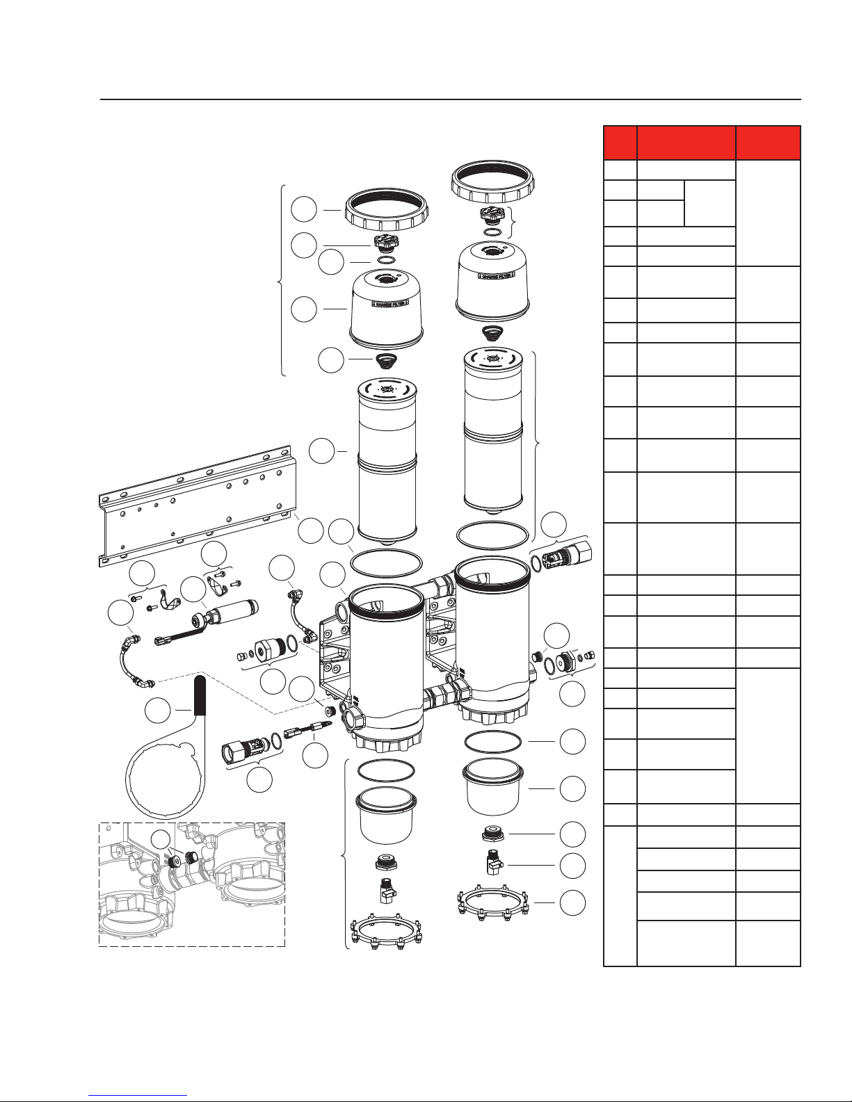
Industrial Pro® Dual Tall
A
B
C
Cover Assembly
D
E
F
I
G
M
N
H
K
J
O
Q
P
O
Bottom
Bowl
Assembly
Vent Cap
Assembly
Filter
Element
Assembly
(includes
part C)
L
O
R
S
T
U
V
W
Part Description
A
Collar
B
Vent Cap
C
O-Ring
D
Cover
E
Filter Spring
Filter Element
F
(includes Part C)
G
O-Ring
H
Industrial Pro
Bracket with
I
Fasteners
Diagnostic Plug Fitting
J
- Extended
Priming Pump
K
(includes Isolators)
Check Valve -
L
Extended
(2) Priming Pump
M
Clamps and
(4) Screws
(2) Priming Pump
N
Hoses and
(4) Fittings
O
Plug 1/2" STOR SP1125
P Bypass Check Valve
Water-In-Fuel (WIF)
Q
Sensor
R Diagnostic Plug Fitting
S
O-Ring
T
Bottom Bowl
U
Drain Flange
V
Drain Valve
Bottom Bracket and
W
Bolts (8)
X
Wrench SP1076
WIF Wiring Harness
WIF LED
Electric Heater
Not
Adapter Fitting, 3/4"
Shown
to 1-1/4"
Adapter Fitting, 1-1/4"
NPT
to M42 x 1.5
Vent Cap
Assembly
SP1053
®
Part
Number
Cover
Assembly
SP1127
FS53014
(includes
Part C)
See page 10
SP1329
SP1205
SP1124
SP1206
SP1133
SP1128
SP1121
SP1328
SP1130
Bottom Bowl
Assembly
SP1134
3950729 S
3946670 S
See page 6
SP1135
3956561 S
Page 4

page 4
Fuel Processor Installation
This system must be installed between the fuel tank
and the transfer fuel pump on the suction side of the
fuel system.
E WARNING: When diesel fuel is circulated
through an operating engine, it
can become very hot. To prevent
personal injury:
E Scalding hazard! Do not allow heated
liquid fuel to come in contact with eyes or
unprotected skin. Always allow the engine
and fuel to cool to ambient temperature
before replacing the fuel filter or performing
service operations which could result in the
spillage of fuel from the fuel system. If this is
not possible, protective clothing (face shield,
insulated hat, gloves, apron) must be worn.
E Heated diesel fuel can form combustible
vapor mixtures in the area around the fuel
source. To eliminate the potential for fire,
keep open flames, sparks or other potential
ignition sources away from the work area,
and do not smoke during filter replacement
or service operations which could result in
the escape of diesel fuel or fuel vapors.
E Always perform engine or vessel fuel system
maintenance in a well ventilated area that is
kept free of bystanders.
E CAUTION: To ensure priming pump hoses
are not kinked by mishandling,
do not lift or handle the fuel
processor by the hoses. Do not
allow the weight of the processor
to rest on the hoses.
Installation Steps
1. With the engine shut down and at ambient
temperature, close the fuel shutoff valve (if
equipped) and place a suitable container under
the fuel filters.
2. Remove the primary fuel filter element assembly,
sedimenter, and/or water separator. Drain
the used element and dispose of it in an
environmentally responsible manner, according
to state and/or federal (EPA) recommendations.
The fuel can be returned to the tank.
Installation of the Industrial Pro should be on
the suction side of the fuel system. Do not
exceed 2.2 lb/in2 (15 kPa) inlet pressure to the
fuel processor.
3. Mount the Industrial Pro® in the desired location
keeping the following points in mind:
a. Mounting the Industrial Pro directly on the
engine is NOT RECOMMENDED.
b. Mount vertically with the cover and element
pointing up.
c. Make sure there is enough top and side
clearance for the cover to be conveniently
removed for filter replacement.
d. Filter service clearance:
Single Short: 3.5" (89 mm) minimum
Single Tall: 6.0" (152 mm) minimum
Dual Tall: 6.0" (152 mm) minimum
E CAUTION: The Industrial Pro functions BEST
when installed so that the Filter
Element is above the "FULL" level
of the fuel tank. The housing can
be installed up to 6' (1.8 m) below
the “FULL” level of the fuel tank.
Installing below the “FULL” level
causes the starting level to be
higher than normal. If mounted
below full tank level, a shut off
valve will be required at the inlet
to allow filter changes without
overflow of fuel. Mounting below
6' (1.8 m) eliminates the SEEING
IS BELIEVING® functionality.
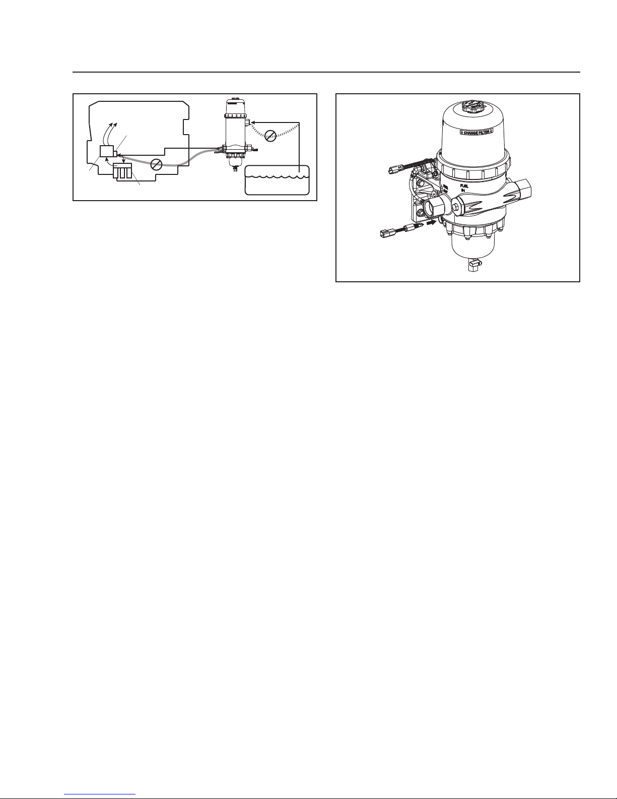
4. Route the fuel supply line from the fuel tank to
the Industrial Pro inlet (see Figure 1). Route a
fuel line from the Industrial Pro outlet to the fuel
pump inlet.
E CAUTION: To avoid fuel line water traps
that can freeze in cold conditions
and restrict, or block, the flow
of fuel to the engine, be certain
that there are no low spots in the
hoses when routing them in the
engine compartment.
Page 5
page 5
Fuel In
Fuel Tank
High
Pressure
Pump
To Injectors/Rail
Low Pressure
Pump
On Engine Filtration
Fuel Out
Figure 1 - Industrial Pro Connections
Note: When the engine is shut off, fuel levels may
drop until the engine is restarted.
5. To minimize restrictions, observe the following
guidelines when plumbing the system.
a. Keep the fuel line routing as smooth as
possible with no low hanging loops which
can trap water.
b. Use 90° elbows only when necessary.
c. If the fuel hoses are made up to length on
the job, be sure that the inner liner of the
fuel hose is not cut by the fitting, creating
potential check valve effects. Also make
sure hoses are clean and free of debris
before installing.
E CAUTION: To avoid damaging the aluminum
fuel housing, do not overtighten
fuel lines or line fittings. Do not
exceed 65 ft-lbs (88 N∙m). See the
table of torque values on page 8.
6. Apply liquid thread sealant to the inlet and outlet
hose threads and connect the hoses to the unit.
Installing a WIF (Water In Fuel) Sensor With
Optional Indicator (LED)
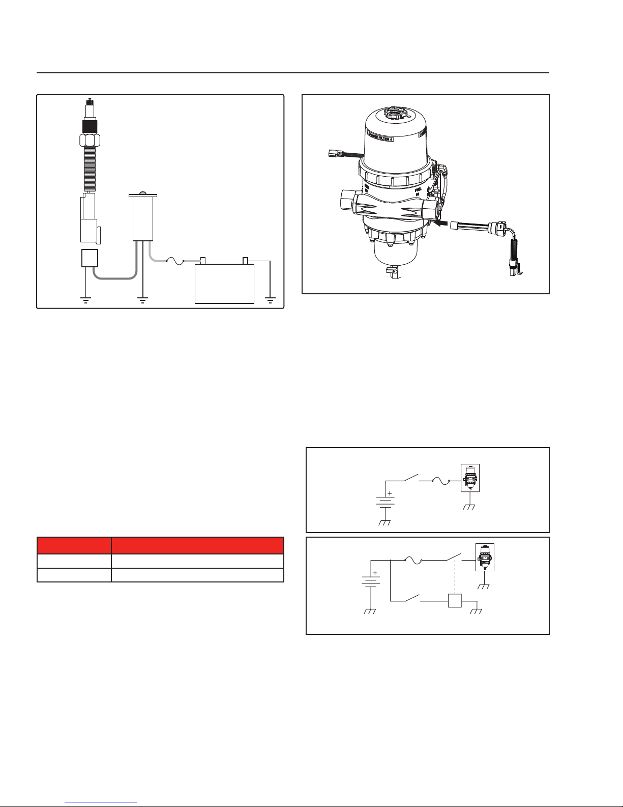
1. Install the WIF Probe (SP1328) into the side of
the Industrial Pro® (see Figure 2). Torque to
20-24 in-lbs (2.3-2.7 N⋅m).
WIF Probe
Figure 2 - WIF Probe Installation
2. Install the WIF wiring harness (3950729 S) on
the WIF Probe. The harness has the following
connections: 12" (304.8 mm) black ground lead
with a 3/8" (9.53 mm) diameter loop end and a
72" (1828.80 mm) green WIF wire.
3. Drill 1/2" (12.70 mm) hole in the control panel
where the WIF LED (3946670 S) is to be located.
a. Installation must have 1.5" (38.10 mm) of
clearance behind dash or control panel.
b. Use caution not to damage nearby
components when drilling.
4. Install WIF LED by pressing firmly into the
drilled hole.
5. Connect the 4" (101.60 mm) black ground
wire on WIF LED to a ground source. Attach
additional black wire as needed.
6. Connect the 12" (304.8 mm) black ground lead
with a 3/8" (9.53 mm) diameter loop end on the
WIF wiring harness to ground source near Fuel
Processor (if applicable).
7. Connect 72" (1828.80 mm) green signal wire
on WIF wiring harness to 4" (101.60 mm) green
signal wire on WIF LED. Use additional green
wire as needed.
8. Locate 12 VDC or 24 VDC power source. Run
red wire from power source to 4" (101.60 mm)
red wire on WIF LED. Add a 1 A in-line fuse
(not included). (See Figure 3.)
Page 6
page 6
WIF
(WaterIn-Fuel)
Sensor
WIF Light
(LED )
Red
Green
WIF
Harness
1 A
Fuse
+–
Figure 3 - WIF Wiring
Note: Use appropriate connectors to attach the
wires. To test the WIF indicator, pour water
into the body of the fuel processor until it
covers the WIF probe. The WIF LED should
illuminate. The volume of fluid necessary to
turn the WIF indicator on is 1500 ml.
Installing an Optional Electric Heater
All units come with pre-drilled ports to allow for preheaters (dual units require two pre-heaters):
Single Short: One port
Single Tall: Two ports
Dual Tall: Four ports (two per body)
Table 1 – 12 and 24 VDC Pre-heaters
Part Number Description
SP1312 12 VDC Pre-heater
SP1313 24 VDC Pre-heater
Pre-heater
Figure 4 - Pre-heater Installation
To install, thread heater into housing and torque
to 15-30 ft-lbs (20.3-40.7 N⋅m). Follow the wiring
diagram in Figure 5.
Refer to equipment owner's manual for more
specific information related to wiring diagrams of the
equipment to which the unit will be applied.
Note: When wiring the electric pre-heater, use a
fuse NOT a circuit breaker.
Key
Controlled
Circuit
Battery
Without Relay
25 A
Fuse*
Battery
With Relay
Use a relay if the available keyed circuit
will not handle a minimum of 25 A.
Key
Controlled
Circuit
25 A
Fuse*
Relay
Industrial
Pro
B
*24 V heaters use 15 A fuse
(supplied in wire harness)
Industrial
8730/51
8586
Pro
B
*24 V heaters use 15 A fuse
(supplied in wire harness)
Figure 5 – Heater Wiring Options
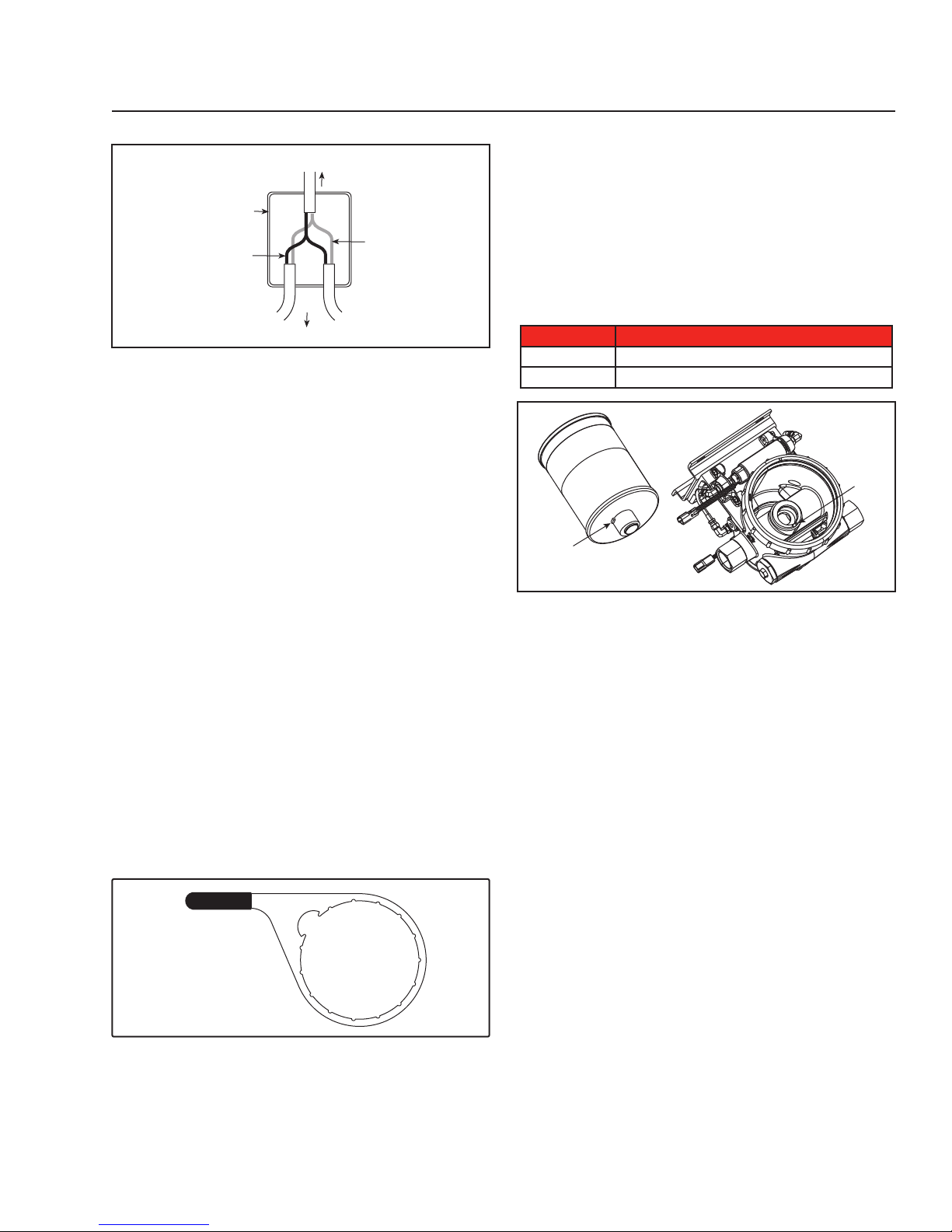
For systems with multiple Industrial Pro® units, the
pre-heater power supply wiring must be split in the
Junction Box. See Figure 6 for wiring a Dual system.
Page 7
page 7
Dual System
To Circuit or
Relay
Junction
Box
Black
To Industrial Pros / Preheaters
Red
Figure 6 – Wiring Dual Filter Systems
Filter Change Procedure
Note: Change the filter only when the fuel level
reaches and remains at the top of the black
band on the filter. The filter may become
dark, however, there is additional filter
capacity and restriction will remain low until
the fuel reaches the black band.
1. Turn off the engine. Remove the vent cap and
dispose of the O-ring. Clean the threads of the
vent cap and on the top of the cover. Set the
vent cap aside.
2. Open the drain valve and drain the fuel
completely from the unit, then close the drain
valve. The unit must be completely drained to
prevent contamination of the clean side of the
filtration system.
3. Using the Collar Wrench (part number SP1076),
loosen the collar. Remove the clear cover and
collar from the Industrial Pro. Discard the cover
O-ring and install a new O-ring (supplied with
the filter) on the cover. Clean the threads on the
collar and body of the Industrial Pro.
Figure 7 – Collar/Vent Cap Wrench
4. Install the new O-ring on the vent cap (supplied
with the filter).
5. Remove the filter element(s) from the Industrial
Pro by pulling upward.
6. Install the new filter element. Figure 8 shows a
key of the filter which fits into a keyway on the
center boss. Position the filter element so the
filter element key is lined up with the keyway on
the center boss of the housing and press the
filter element into the housing. Ensure the filter
element is fully seated by firmly pushing on the
end plate.
Table 2 – Industrial Pro Replacement Filters
Part Number Description
FS53014
FS53015
Key
EleMax™ NanoNet™ 5 micron (tall)
EleMax NanoNet 5 micron (short)
Keyway
Figure 8 – Key and Keyway
7. After checking to make sure the new O-ring seal
is seated correctly on the base of the cover,
install the cover and collar. Simultaneously apply
modest pressure to the top of the cover and turn
the collar until it no longer spins freely. Using the
collar wrench, tighten the collar the distance of
two additional ribs.
8. Prime the fuel system according to the steps
in the "Priming the Fuel System" section in this
manual. (The vent cap will be returned to the
Industrial Pro during the priming process).
Priming the Fuel System
1. Check to make sure the drain valve at the base
of the Industrial Pro® is closed. Close the fuel
shutoff valve (if equipped).
2. Remove the vent cap from the top of the clear
cover. Fill the Industrial Pro full of clean fuel.
Tighten the vent cap (tighten by hand only) until
it “clicks.”
3. Open the fuel shutoff valve (if equipped). Start
the engine. When the lubrication system reaches
its normal operating pressure, increase engine
speed to high idle for one to two minutes.
Loosen the vent cap until the fuel level drops
to just above the collar. Tighten the vent cap
(tighten by hand only) until it “clicks.”
Page 8
page 8
Note: The clear filter cover will not fill completely
during engine operation. It will gradually fill
over time and the fuel level will rise as the
filter becomes clogged.
Draining Contaminants
1. Turn off the engine and open the vent cap.
2. Place a suitable container under the drain valve
at the base of the Industrial Pro and open the
drain valve.
3. Water and contaminants will flow into the
container. When fuel begins to flow out of the
drain, close the drain valve.
4. Tighten the vent cap by hand until it “clicks.”
5. Start the engine. Raise the RPM for one minute
to purge the air from the system.
Servicing the Primer Pump
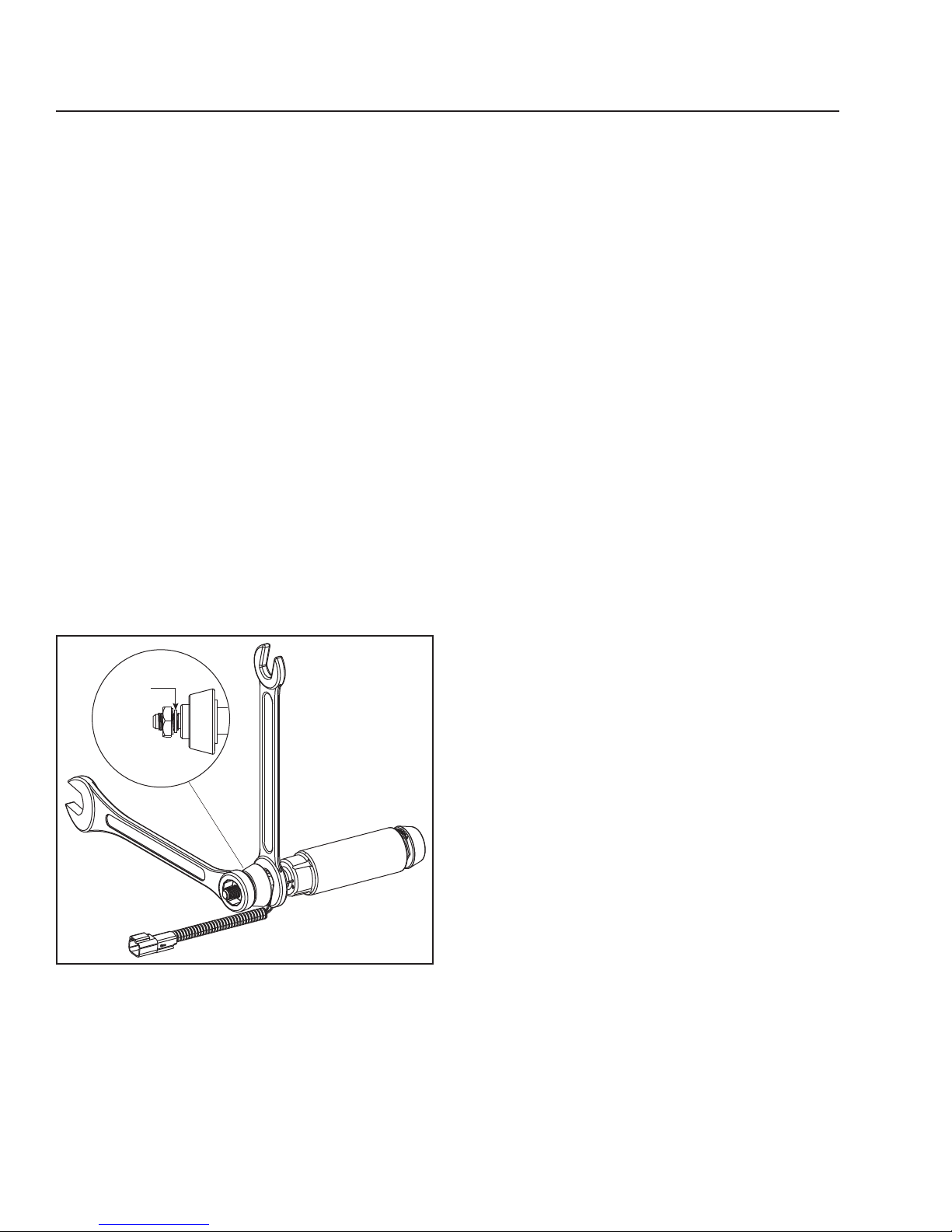
1. Remove the fitting on the end of the pump using
two wrenches to hold the end stationary as the
fitting is loosened.
2. The washer on the fittings MUST be in place
when reassembled.
Suggested Preventive Maintenance
Weekly – Drain water.
Every Filter Change – Change o-rings.
Every 12 Months – Check all electrical connections
for corrosion. Check all fuel fittings for leaks.
Extreme winter or salt corrosion environments may
require lubrication of the top collar threads with antiseize lubricant every 180 days.
Changing the Fuel Inlet Direction
for Industrial Pro Single and Dual
Configurations
To change the fuel inlet from the left to right, or from
the right to left, exchange the inlet fitting (including
check valve) with the threaded plug on the opposite
side of the housing. Torque both of the fittings to
55-65 ft-lb (74.6-88.1 N⋅m).
Changing the Fuel Outlet Direction for
Single Configurations Only
Washer
Figure 9 – Removing the Primer Pump Fitting
To change the fuel outlet from the left to right,
or from the right to left, both the fittings and the
priming pump require a directional change as
follows:
1. Remove the outlet fitting with the bypass valve
attached.
2. Remove the outlet plug from the opposite side of
the housing.
3. Exchange the fitting and plug to the opposite
sides and torque to 55-65 ft-lb (74.6-88.1 N⋅m).
4. Disconnect the hoses attaching the priming
pump to the housing.
5. Remove the bolts securing the priming pump
straps.
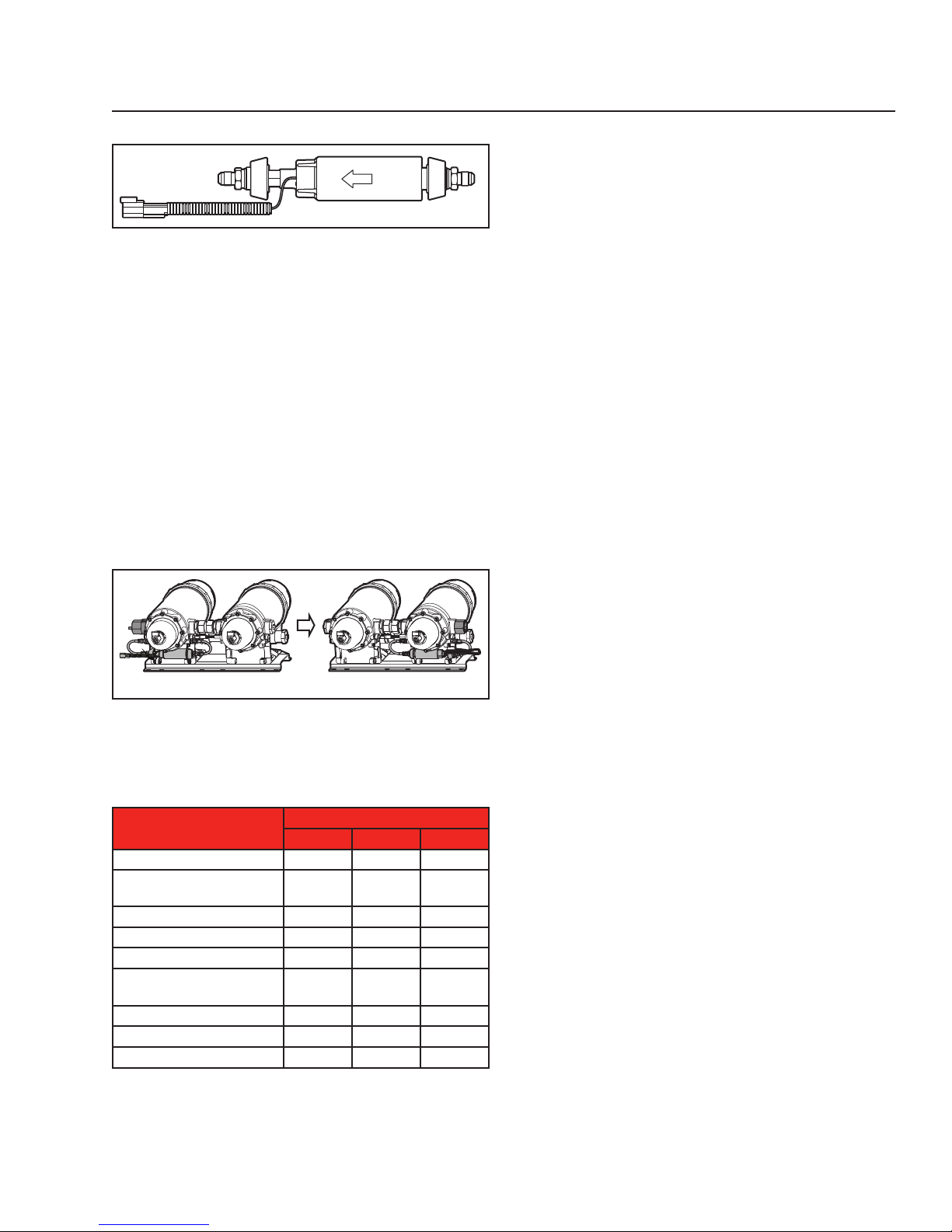
6. Turn the priming pump to ensure that the arrow
etched on the pump housing is pointed in the
direction of the outlet of the housing.
7. Reinstall bolts securing the priming pump straps
and torque to 8-10 ft-lb (10.8-13.6 N⋅m).
8. Reinstall the hoses and torque to 10-15 ft-lb
(13.6-20.3 N⋅m).
Page 9
FUEL
OUT
Figure 10 – Primer Pump Fitting
Changing the Fuel Outlet Direction for
Dual Configurations Only
The same procedure applies to the dual
configuration as with the single configuration,
but the priming pump must also be moved to the
housing with the fuel outlet fitting attached. Again,
ensure the flow direction arrow is pointed toward
the outlet fitting.
For instance, if changing from a fuel out left
configuration to a fuel out right configuration, the
priming pump must be moved from the left housing
to the right housing.
page 9
Left Right
Figure 11 – Changing From a Fuel Out Left to a Fuel
Out Right Configuration
Torque Values
Application
WIF Probe to Housing
Fuel Connection Fittings to
Housing Body
Heater to Housing
Drain Valve to Bowl
Primer Pump Strap to Body
Primer Pump Fittings to Housing
Body
Pump Inlet/Outlet Hose to Fittings
Assembly to Mounting Bracket
Collar to Bottom Bowl
in-lb ft-lb N⋅m
20-24 1.67-2.0 2.3-2.7
Torque
55-65 74.6-88.1
15-30 20.3-40.7
10-15 13.6-20.3
8-10 10.8-13.6
13-15 17.6-20.3
10-15 13.6-20.3
35-50 47.5-67.8
8-10 10.8-13.6
Page 10
page 10
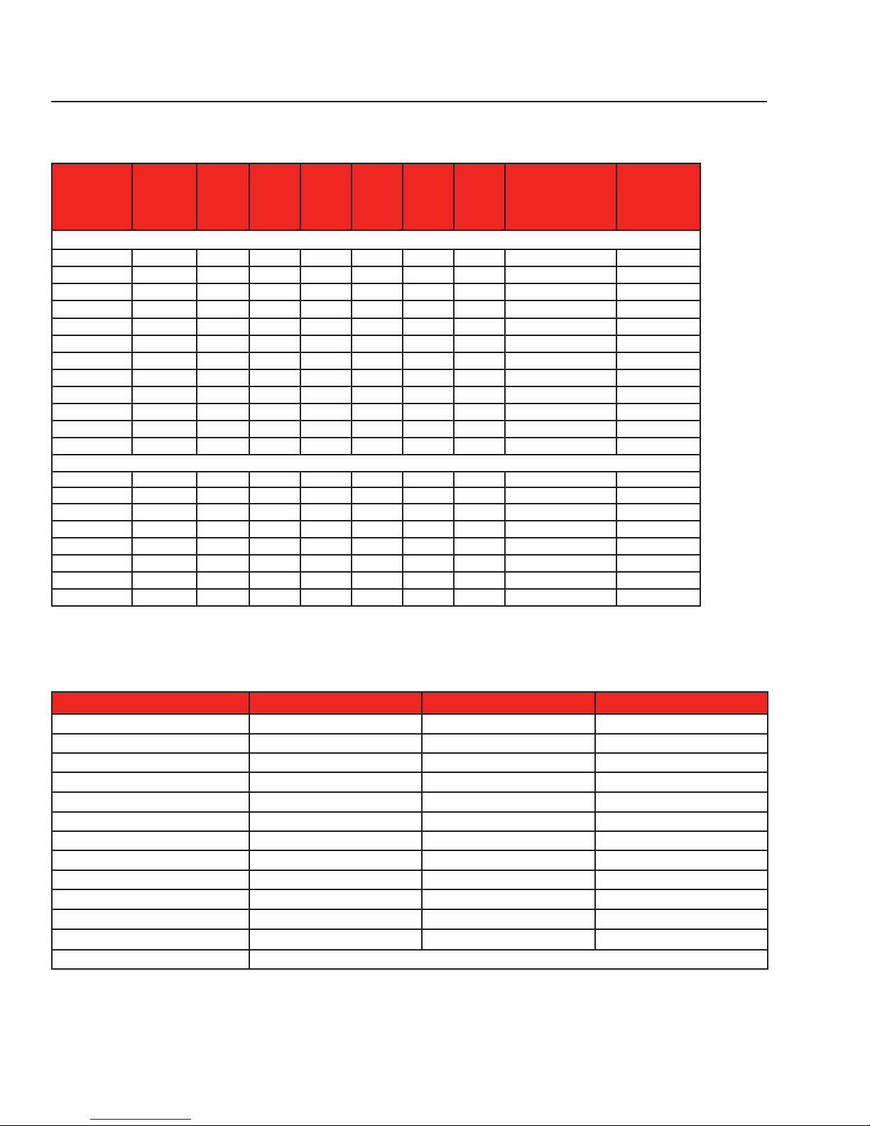
Industrial Pro® Ordering Information
Housing Part
Number
FH23900 FS53015
FH23904 FS53015
FH23916 FS53015
FH23917 FS53015
FH23901 FS53014
FH23903 FS53014
FH23905 FS53014
FH23906 FS53014
FH23912 FS53014
FH23913 FS53014
FH23914 FS53014
FH23915 FS53014
FH23907 FS53014*
FH23908 FS53014*
FH23910 FS53014*
FH23911 FS53014*
FH23918 FS53014
FH23919 FS53014
FH23920 FS53014
FH23921 FS53014
* Requires two filter elements
Filter
Element
Short/
Tall
Short Yes Yes Yes Yes No In Right/Out Left 1-1/4" NPTF
Short Yes Yes Yes Yes No In Left/Out Right 1-1/4" NPTF
Short No Yes Yes Yes No In Right/Out Left 1-1/4" NPTF
Short No Yes Yes Yes No In Left/Out Right 1-1/4" NPTF
Tall Yes Yes Yes Yes No In Left/Out Right 1-1/4" NPTF
Tall Yes Yes Yes Yes No In Right/Out Left 1-1/4" NPTF
Tall Yes Yes Yes Yes No In Left/Out Left 1-1/4" NPTF
Tall Yes Yes Yes Yes No In Right/Out Right 1-1/4" NPTF
Tall No Yes Yes Yes No In Right/Out Left 1-1/4" NPTF
Tall No Yes Yes Yes No In Left/Out Right 1-1/4" NPTF
Tall No Yes Yes Yes No In Left/Out Left 1-1/4" NPTF
Tall No Yes Yes Yes No In Right/Out Right 1-1/4" NPTF
Tall Yes Yes Yes Yes No In Right/Out Right 1-1/4" NPTF
Tall Yes Yes Yes Yes No In Right/Out Left 1-1/4" NPTF
Tall Yes Yes Yes Yes No In Left/Out Right 1-1/4" NPTF
Tall Yes Yes Yes Yes No In Left/Out Left 1-1/4" NPTF
Tall No Yes Yes Yes No In Right/Out Left 1-1/4" NPTF
Tall No Yes Yes Yes No In Left/Out Right 1-1/4" NPTF
Tall No Yes Yes Yes No In Left/Out Left 1-1/4" NPTF
Tall No Yes Yes Yes No In Right/Out Right 1-1/4" NPTF
Primer
Pump WIF
Clear
Bowl
Single
Dual
Bracket
Included Heater
Fuel In &
Fuel Out Port Size
Industrial Pro® Specifications
Specification Single Short Single Tall Dual Tall
Height Overall 20" (508 mm) 28" (711 mm) 28" (711 mm)
Depth Overall 12" (305 mm) 12" (305 mm) 12" (305 mm)
Width, max 11.2" (284 mm) 13.9" (352 mm) 23.8" (604 mm)
Weight (Dry) 29 lbs (13.2 kg) 39 lbs (17.7 kg) 75 lbs (34.0 kg)
Weight (Wet) 37 lbs (16.8 kg) 57 lbs (25.6 kg) 112 lbs (50.8 kg)
Fuel Capacity (w/o filter)
Fuel Connections 1-1/4" NPT 1-1/4" NPT 1-1/4" NPT
Fuel Flow Rate 300 gal/hr (12.6 L/min) 600 gal/hr (37.9 L/min) 1200 gal/hr (63.1 L/min)
Bottom Bowl Water Holding Capacity 29 fl oz (860 ml) 29 fl oz (860 ml) 58 fl oz (1720 ml)
Filter Service Clearance Min. 3.5" (89 mm) Min. 6.0" (152 mm) Min. 6.0" (152 mm)
Electrical Heater Options 12 VDC or 24 VDC 12 VDC or 24 VDC 12 VDC or 24 VDC
Primer Pump Supply Voltage: 24 VDC, 6 A
Fuel Types Compatible for use with Diesel #1, Diesel #2, Kerosene, Biodiesel B20, and JP8
Specifications subject to change without notice.
1.1 gal (4.3 L) 2.5 gal (9.5 L) 5.0 gal (19 L)
Supply Voltage: 24 VDC, 6 A Supply Voltage: 24 VDC, 6 A
Page 11
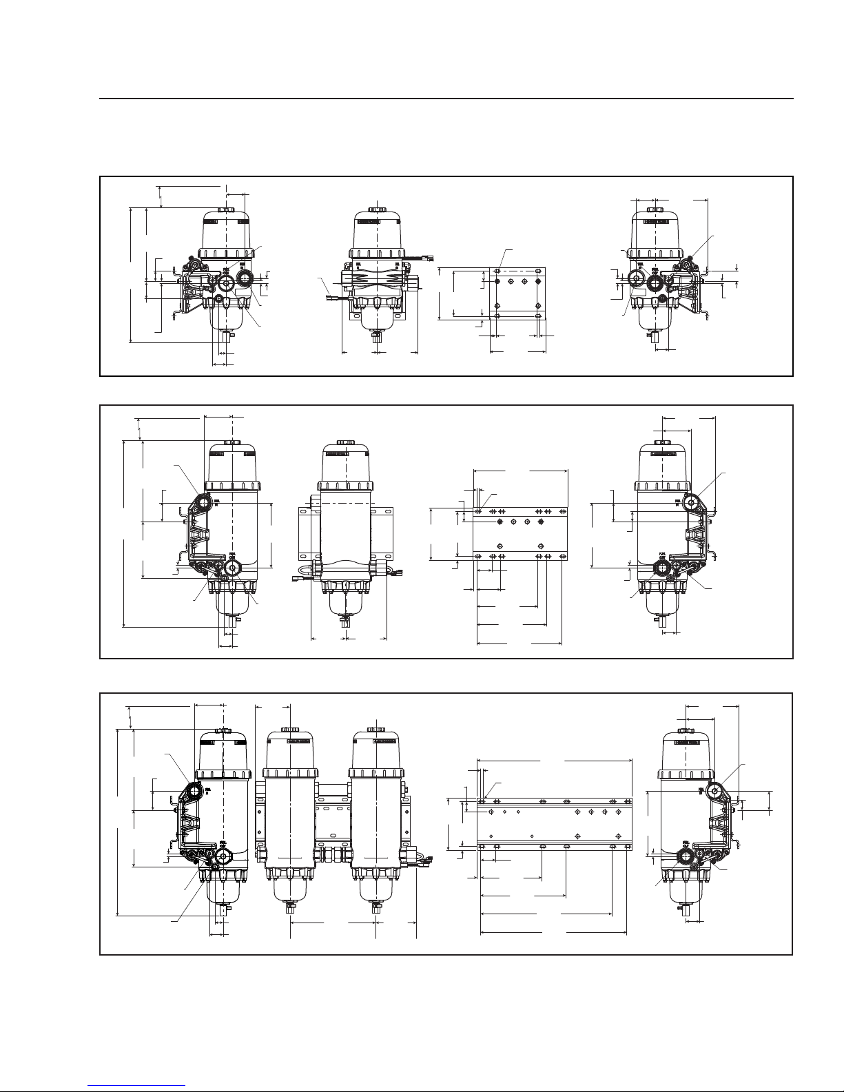
Dimensions
Industrial Pro® Single Short
page 11
20.00
(508.0)
Max.
10.78
(273.8)
2.53
(64.1)
0.32
(8.0)
Service Height
3.5 (88.9)
1.50
(38.1)
2.75 (69.9)
7/8"-14 UNF-2B
Optional Heater
O-Ring Boss Port
Fuel In
1-1/4"-11-1/2 NPTF
M14 Diagnostic Port
Optional Fuel Out
1.08 (27.4)
2.00 (50.8)
Industrial Pro® Single Tall
Service Height
11.92
(302.8)
27.600
(701.1)
Max.
8.32
(211.3)
7/8"-14 UNF-2B
Optional Heater
O-Ring Boss Port
6.0 (152.4)
Fuel In
1-1/4"-11-1/2
NPTF
2.77
(70.5)
.040
(10.2)
4.20 (106.7)
9.56
(242.7)
M14
Diagnostic
Port Optional
Fuel Out
1.20 (30.5)
2.00 (50.8)
0.75
(19.1)
.040
(10.2)
WIF
Sensor
5.08
(128.9)
5.20
(132.1)
5.97
(151.6)
5.97
(151.6)
All dimensions are in inches (millimeters)
∅ 0.22
(5.6)
(x4)
7.70
1.50
(195.6)
(38.1)
6.60
(167.6)
0.55 (14.0)
0.92 (23.4)
All dimensions are in inches (millimeters)
0.35
(8.9)
1.50 (38.1)
6.60
7.70
(167.6)
(195.6)
0.55 (14.0)
0.52 (13.2)
6.00
(152.4)
8.20
(208.3)
13.85
(351.8)
∅ 0.22
(5.6) (x12)
2.20
(55.9)
3.50
(88.9)
8.96
(227.6)
10.26
(260.60
12.46
(316.5)
0.35
(8.9)
Fuel Out
0.75
(19.1)
0.40
(10.2)
M14
Diagnostic
Port
Optional
Fuel In
2.77
(70.5)
9.56
(38.1)
(242.7)
0.40
(10.2)
Fuel Out
1-1/4"-11-1/2
NPTF
1-1/4"-11-1/2 NPTF
2.75
(69.9)
1.50
7.75
(196.8)
2.00
(50.8)
(Left-In, Right-Out Unit Shown)
7.75
(196.8)
4.20
(106.7)
2.00
(50.8)
(Left-In, Right-Out Unit Shown)
7/8"-14 UNF-2B
Optional Heater
O-Ring Boss Port
1.50
(38.1)
0.32
(8.0)
M14
Diagnostic
Port
Optional
Fuel In
7/8"-14 UNF-2B
Optional Heater
O-Ring Boss Port
Industrial Pro® Dual Tall
4.20
Service Height
Fuel In
1-1/4"-11-1/2
NPTF
11.92
(302.8)
27.600
(701.1)
Max.
8.32
(211.3)
.040
(10.2)
7/8"-14 UNF-2B
Optional Heater
O-Ring Boss Port
M14 Diagnostic
Port Optional
Fuel Out
6.0 (152.4)
2.77
(70.5)
(106.7)
1.20 (30.5)
2.00 (50.8)
5.08
(128.9)
Fuel In
12.69
(322.3)
5.97
(151.6)
Fuel Out
All dimensions are in inches (millimeters)
1.50
(38.1)
7.70
(195.6)
0.55
(14.0)
(12.7)
0.35
(8.9)
6.60
(167.6)
0.50
(227.6)
∅ 0.22
(5.6) (x12)
2.20
(55.9)
8.96
12.46
(316.5)
22.75
(577.9)
19.22
(488.2)
21.42
(544.1)
7.75
(196.8)
4.20
(106.7)
9.56
(242.7)
2.00
(50.8)
7/8"-14
UNF-2B
Optional
Heater
O-Ring
Boss Port
0.40
(10.2)
Fuel Out
1-1/4"-
11-1/2
NPTF
(Left-In, Right-Out Unit Shown)
M14
Diagnostic
Port
Optional
Fuel In
1.50
(38.1)
2.77
(70.5)
Page 12

page 12
For more information, visit
cumminsfiltration.com
LT36333 Rev. 2
©2015 Cummins Filtration Inc.
Printed in the U.S.A.
 Loading...