

Fleetguard FH23916, FH23905, FH23901, FH23906, FH23913 Installation Instructions Manual
...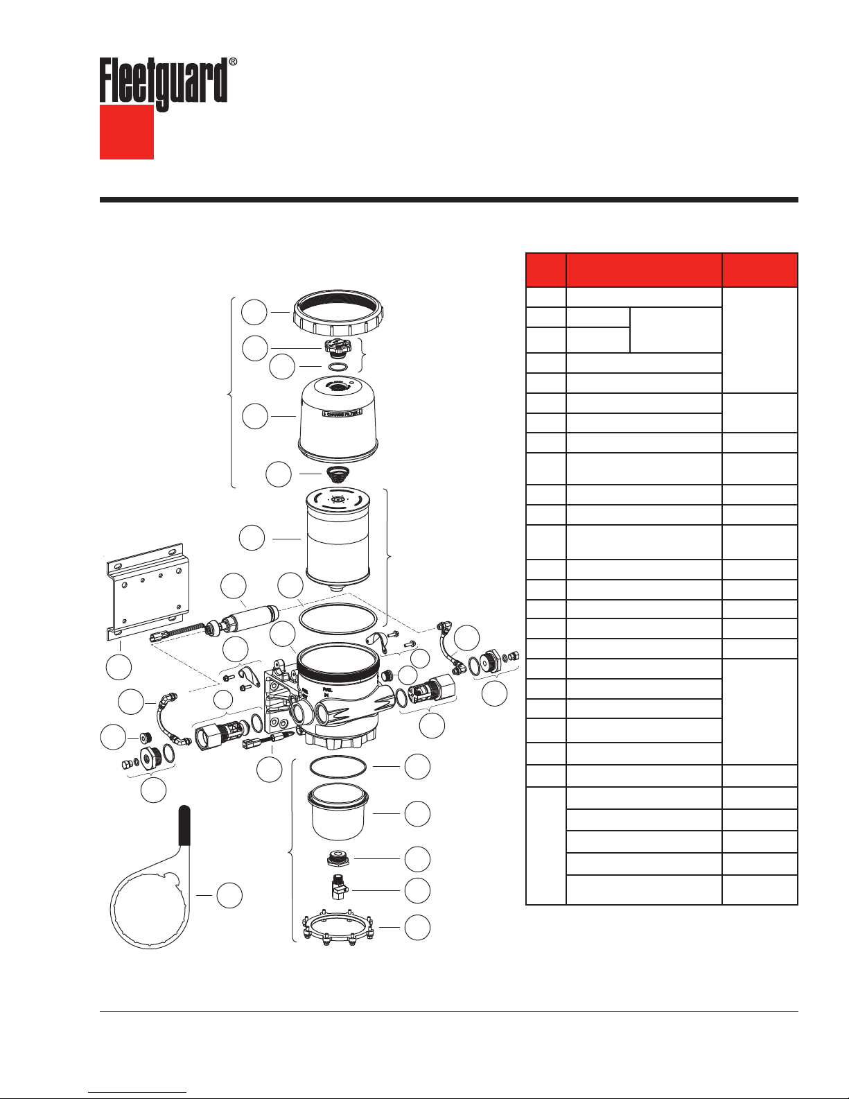
Industrial Pro® FH239 Series
Filter/Separator/Warmer
Installation Instructions
M
K
L
Industrial Pro® Single Short
Cover Assembly
O
H
N
W
A
B
D
F
I
Bottom
Assembly
P
Bowl
E
C
Part Description
A
Collar
B
Vent Cap
C
Vent Cap Assembly
Filter Element Assembly
(includes part C)
G
J
I
M
L
O
Q
R
S
T
U
O-Ring
D
Cover
E
Filter Spring
F
Filter Element (includes Part C)
G
O-Ring
H
Priming Pump (includes Isolators) SP1124
(2) Priming Pump Clamp and
I
(4) Screws
J
Industrial Pro
K
Bracket with Fasteners SP1131
(2) Priming Pump Hoses and
L
(4) Fittings
M
Plug 1/2" STOR SP1125
N
Bypass Check Valve SP1121
O Diagnostic Plug Fitting
P
Water-In-Fuel (WIF) Sensor SP1328
Q
Check Valve SP1120
R
O-Ring
S
Bottom Bowl
T
Drain Flange
U
Drain Valve
V
Bottom Bracket and Bolts (8)
W
Wrench SP1076
WIF Wiring Harness
WIF LED
Not
Electric Heater
Shown
Adapter Fitting, 3/4" to 1-1/4"
Adapter Fitting, 1-1/4" NPT
to M42 x 1.5
Vent Cap
Assembly
SP1053
®
Part
Number
Cover
Assembly
SP1127
FS53015
(includes Part C)
SP1133
See page 10
SP1128
SP1130
Bottom Bowl
Assembly
SP1134
3950729 S
3946670 S
See page 6
SP1135
3956561 S
E CAUTION: These instructions are intended for use by professional mechanics who are trained in the proper
use of power and hand tools, using appropriate safety precautions (including eye protection).
V
page 2
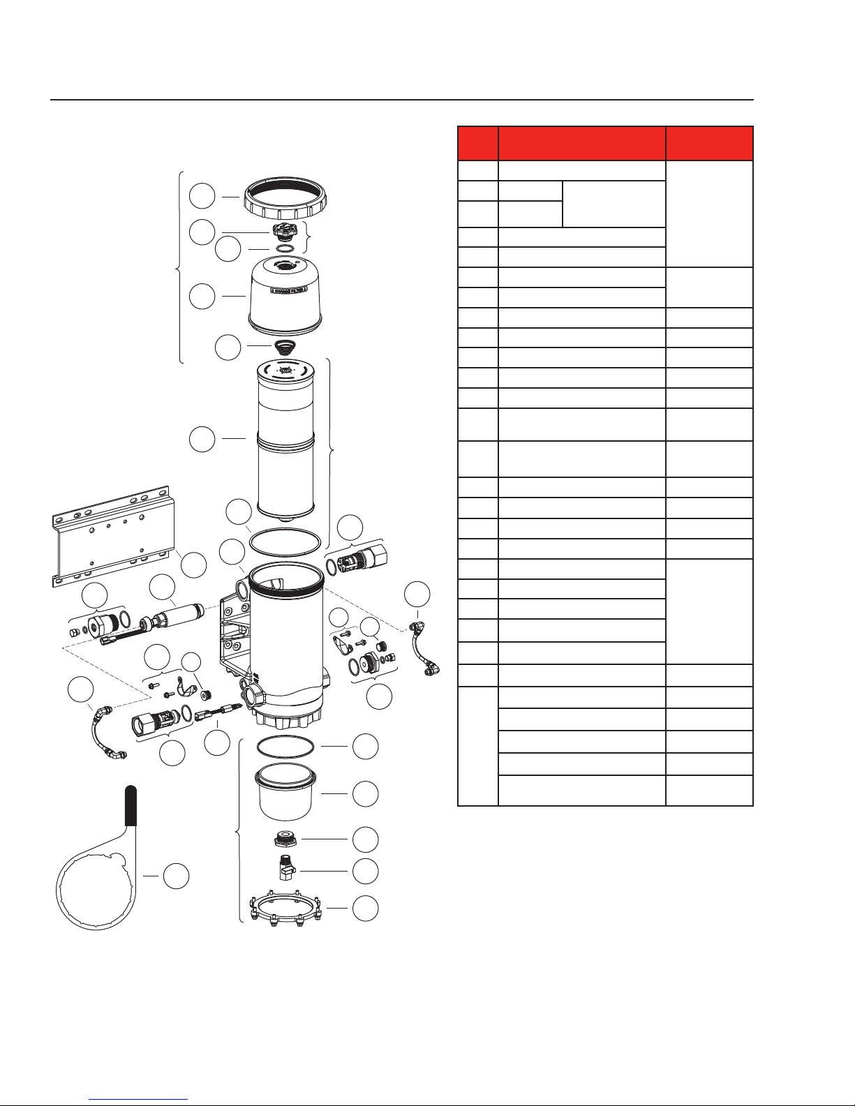
Cover Assembly
J
N
Industrial Pro® Single Tall
A
M
K
P
B
C
D
E
F
G
H
I
O
Q
Bottom
Bowl
Assembly
Vent Cap Assembly
Filter Element Assembly
(includes part C)
L
M
S
T
U
Part Description
A
Collar
B
Vent Cap
C
O-Ring
D
Cover
E
Filter Spring
F
Filter Element (includes Part C)
G
O-Ring
H
Industrial Pro
I
Bracket with Fasteners SP1132
J Diagnostic Plug Fitting - Extended
K
Priming Pump (includes Isolators) SP1124
L
Check Valve - Extended SP1206
(2) Priming Pump Clamps and
M
(4) Screws
(2) Priming Pump Hoses and
N
(4) Fittings
O
Plug 1/2" STOR SP1125
P Bypass Check Valve
Q
Water-In-Fuel (WIF) Sensor SP1328
R Diagnostic Plug Fitting
S
O-Ring
T
N
O
R
Bottom Bowl
U
Drain Flange
V
Drain Valve
W
Bottom Bracket and Bolts (8)
X
Wrench SP1076
WIF Wiring Harness
WIF LED
Not
Electric Heater
Shown
Adapter Fitting, 3/4" to 1-1/4"
Adapter Fitting, 1-1/4" NPT
to M42 x 1.5
Vent Cap Assembly
SP1053
®
Part
Number
Cover Assembly
SP1127
FS53014
(includes Part C)
See page 10
SP1205
SP1133
SP1128
SP1121
SP1130
Bottom Bowl
and Drain Valve
Assembly
SP1134
3950729 S
3946670 S
See page 6
SP1135
3956561 S
X
V
W
page 3
N
M
X
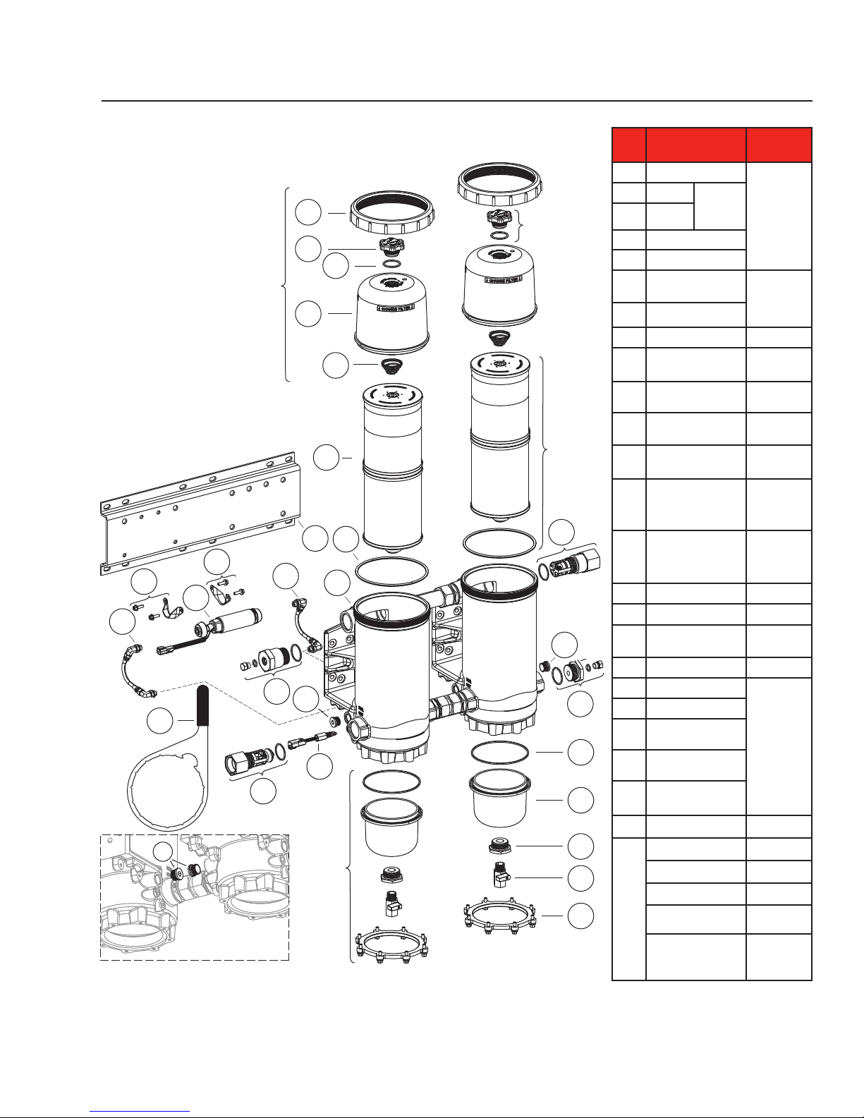
Industrial Pro® Dual Tall
A
B
C
Cover Assembly
D
E
F
I
G
M
N
H
K
J
O
Q
P
O
Bottom
Bowl
Assembly
Vent Cap
Assembly
Filter
Element
Assembly
(includes
part C)
L
O
R
S
T
U
V
W
Part Description
A
Collar
B
Vent Cap
C
O-Ring
D
Cover
E
Filter Spring
Filter Element
F
(includes Part C)
G
O-Ring
H
Industrial Pro
Bracket with
I
Fasteners
Diagnostic Plug Fitting
J
- Extended
Priming Pump
K
(includes Isolators)
Check Valve -
L
Extended
(2) Priming Pump
M
Clamps and
(4) Screws
(2) Priming Pump
N
Hoses and
(4) Fittings
O
Plug 1/2" STOR SP1125
P Bypass Check Valve
Water-In-Fuel (WIF)
Q
Sensor
R Diagnostic Plug Fitting
S
O-Ring
T
Bottom Bowl
U
Drain Flange
V
Drain Valve
Bottom Bracket and
W
Bolts (8)
X
Wrench SP1076
WIF Wiring Harness
WIF LED
Electric Heater
Not
Adapter Fitting, 3/4"
Shown
to 1-1/4"
Adapter Fitting, 1-1/4"
NPT
to M42 x 1.5
Vent Cap
Assembly
SP1053
®
Part
Number
Cover
Assembly
SP1127
FS53014
(includes
Part C)
See page 10
SP1329
SP1205
SP1124
SP1206
SP1133
SP1128
SP1121
SP1328
SP1130
Bottom Bowl
Assembly
SP1134
3950729 S
3946670 S
See page 6
SP1135
3956561 S

page 4
Fuel Processor Installation
This system must be installed between the fuel tank
and the transfer fuel pump on the suction side of the
fuel system.
E WARNING: When diesel fuel is circulated
through an operating engine, it
can become very hot. To prevent
personal injury:
E Scalding hazard! Do not allow heated
liquid fuel to come in contact with eyes or
unprotected skin. Always allow the engine
and fuel to cool to ambient temperature
before replacing the fuel filter or performing
service operations which could result in the
spillage of fuel from the fuel system. If this is
not possible, protective clothing (face shield,
insulated hat, gloves, apron) must be worn.
E Heated diesel fuel can form combustible
vapor mixtures in the area around the fuel
source. To eliminate the potential for fire,
keep open flames, sparks or other potential
ignition sources away from the work area,
and do not smoke during filter replacement
or service operations which could result in
the escape of diesel fuel or fuel vapors.
E Always perform engine or vessel fuel system
maintenance in a well ventilated area that is
kept free of bystanders.
E CAUTION: To ensure priming pump hoses
are not kinked by mishandling,
do not lift or handle the fuel
processor by the hoses. Do not
allow the weight of the processor
to rest on the hoses.
Installation Steps
1. With the engine shut down and at ambient
temperature, close the fuel shutoff valve (if
equipped) and place a suitable container under
the fuel filters.
2. Remove the primary fuel filter element assembly,
sedimenter, and/or water separator. Drain
the used element and dispose of it in an
environmentally responsible manner, according
to state and/or federal (EPA) recommendations.
The fuel can be returned to the tank.
Installation of the Industrial Pro should be on
the suction side of the fuel system. Do not
exceed 2.2 lb/in2 (15 kPa) inlet pressure to the
fuel processor.
3. Mount the Industrial Pro® in the desired location
keeping the following points in mind:
a. Mounting the Industrial Pro directly on the
engine is NOT RECOMMENDED.
b. Mount vertically with the cover and element
pointing up.
c. Make sure there is enough top and side
clearance for the cover to be conveniently
removed for filter replacement.
d. Filter service clearance:
Single Short: 3.5" (89 mm) minimum
Single Tall: 6.0" (152 mm) minimum
Dual Tall: 6.0" (152 mm) minimum
E CAUTION: The Industrial Pro functions BEST
when installed so that the Filter
Element is above the "FULL" level
of the fuel tank. The housing can
be installed up to 6' (1.8 m) below
the “FULL” level of the fuel tank.
Installing below the “FULL” level
causes the starting level to be
higher than normal. If mounted
below full tank level, a shut off
valve will be required at the inlet
to allow filter changes without
overflow of fuel. Mounting below
6' (1.8 m) eliminates the SEEING
IS BELIEVING® functionality.
4. Route the fuel supply line from the fuel tank to
the Industrial Pro inlet (see Figure 1). Route a
fuel line from the Industrial Pro outlet to the fuel
pump inlet.
E CAUTION: To avoid fuel line water traps
that can freeze in cold conditions
and restrict, or block, the flow
of fuel to the engine, be certain
that there are no low spots in the
hoses when routing them in the
engine compartment.
 Loading...