

Fleetguard Diesel Pro FH236 Series, Diesel Pro FH235 Series, Diesel Pro FH241 Series Installation Instructions Manual
A
FH235 Cover
Assembly
Includes
Vent Cap,
Vent Cap O-Ring,
Collar, Cover,
Cover O-Ring,
and Spring
F
Diesel Pro® FH235, FH236 and FH241
Series Filter/Separator/Warmer
Installation Instructions
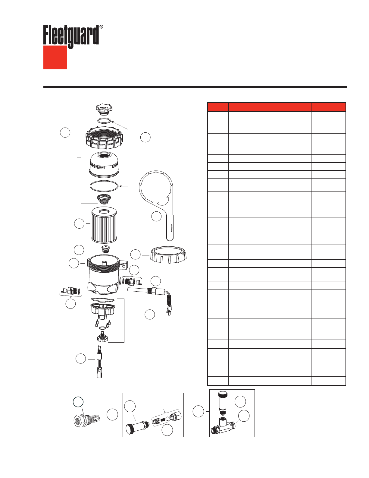
Parts ListDiesel Pro® 235
Part Description Part Number
FH235 Cover Assembly (includes Vent
Cap, Vent Cap O-Ring, Collar, Cover,
A
Cover O-Ring, and Spring)
B
Biodiesel O-Ring Pack
Includes Vent Cap O-Ring
and Cover O-Ring
K
C
D
J
E
F
G
Shown
H
Bottom Bowl Assembly
Includes Bottom
Bowl Seal,
Bottom Bowl, Screws,
Drain Valve O-Ring,
and Drain Valve
I
Manual Primer Pumps
Biodiesel O-Ring Pack – only
required for >B5 fuel (includes Vent
B
Cap O-Ring and Cover O-Ring)
Filter Element See page 9
C
Check Valve Assembly
D
Diesel Pro® FH235, Unheated See page 12
E
Adapter - 7/8"-14 to M16 x 1.5
F
Adapter - 7/8"-14 to 3/8" NPT
Pre-Heater, 12 V, 195 W, WP Connector
Pre-Heater, 24 V, 195 W, WP Connector
G
Pre-Heater, 24 V, 195 W, Tyco Connector
120 VAC, 75 W Heater
Bottom Bowl Assembly (includes
Bottom Bowl Seal, Bottom Bowl, Screws,
H
Drain Valve O-Ring, and Drain Valve)
Water-In-Fuel (WIF) Sensor
I
Collar for Reduced Clearance
J
Applications (optional)
Collar Wrench, Metal
K
WIF Wiring Harness
Not
WIF LED
Manual Primer Pump Plunger
L
Primer Pump Check Valve (M16)
Primer Pump Check Valve (M18)
M
Primer Pump Check Valve (3/8")
Primer Pump Check Valve (7/8")
Primer Pump Service Kit (M16)
Primer Pump Service Kit (M18)
N
Primer Pump Service Kit (3/8")
Primer Pump Service Kit
O
Check Valve Assembly (M18)
Check Valve Assembly (M16)
P
Check Valve Assembly (7/8")
Check Valve Assembly (3/8")
Check Valve Assembly Kit
Q
3973506 S
3950444 S
SP1413
3973689 S
3980209 S
SP1312
SP1313
SP1314
3980208 S
3972255 S
3957158 S
3945059 S
3944458 S
3950729 S
3946670 S
3975110 S
3981659 S
3981660 S
SP1642
3975109 S
3979203 S
3979202 S
SP1632
3975111 S
SP72127
SP72128
SP72129
SP72130
SP1644
M
O
CAUTION: These instructions are intended for use by professional mechanics who are trained in the proper
use of power and hand tools, using appropriate safety precautions (including eye protection).
L
N
L
P
Q
page 2
A
FH236 Cover
Assembly
Includes
Vent Cap,
Vent Cap O-Ring,
Collar, Cover,
Cover O-Ring,
and Spring
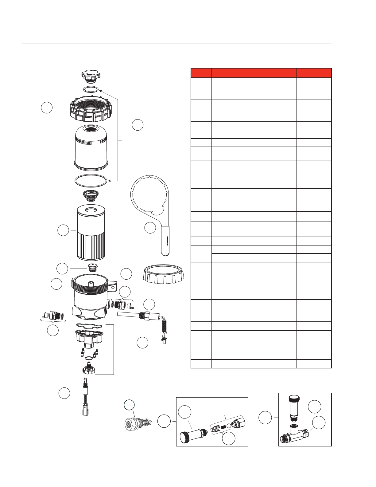
Parts ListDiesel Pro® 236
Part Description Part Number
FH236 Cover Assembly includes Vent
Cap, Vent Cap O-Ring, Collar, Cover,
A
Cover O-Ring, and Spring)
Biodiesel O-Ring Pack – only
required for >B5 fuel (includes Vent
B
Cap O-Ring and Cover O-Ring)
B
Biodiesel O-Ring Pack
Includes Vent Cap O-Ring
and Cover O-Ring
C
K
Shown
D
J
E
F
G
F
H
Bottom Bowl Assembly
Includes Bottom
Bowl Seal,
Bottom Bowl, Screws,
Drain Valve O-Ring,
and Drain Valve
Filter Element See page 9
C
Check Valve Assembly
D
Diesel Pro® FH236, Unheated See page 12
E
Adapter - 7/8"-14 to M16 x 1.5
F
Adapter - 7/8"-14 to 3/8" NPT
Pre-Heater, 12 V, 195 W, WP Connector
Pre-Heater, 24 V, 195 W, WP Connector
G
Pre-Heater, 24 V, 195 W, Tyco Connector
120 VAC, 75 W Heater
Bottom Bowl Assembly (includes
Bottom Bowl Seal, Bottom Bowl, Screws,
H
Drain Valve O-Ring, and Drain Valve)
Water-In-Fuel (WIF) Sensor
I
Collar for Reduced Clearance
J
Applications (optional)
Collar Wrench, Metal
K
WIF Wiring Harness
Not
WIF LED
Manual Primer Pump Plunger
L
Primer Pump Check Valve (M16)
Primer Pump Check Valve (M18)
M
Primer Pump Check Valve (3/8")
Primer Pump Check Valve (7/8")
Manual Primer Pump (M16)
Manual Primer Pump (M18)
N
Manual Primer Pump (3/8")
Primer Pump Service Kit
O
Check Valve Assembly (M18)
Check Valve Assembly (M16)
P
Check Valve Assembly (7/8")
Check Valve Assembly (3/8")
Check Valve Service Kit
Q
3974145 S
3950444 S
SP1413
3973689 S
3980209 S
SP1312
SP1313
SP1314
3980208 S
3972255 S
3957158 S
3945059 S
3944458 S
3950729 S
3946670 S
3975110 S
3981659 S
3981660 S
SP1642
3975109 S
3979203 S
3979202 S
SP1632
3975111 S
SP72127
SP72128
SP72129
SP72130
SP1644
Manual Primer Pumps
I
M
O
L
L
N
P
Q
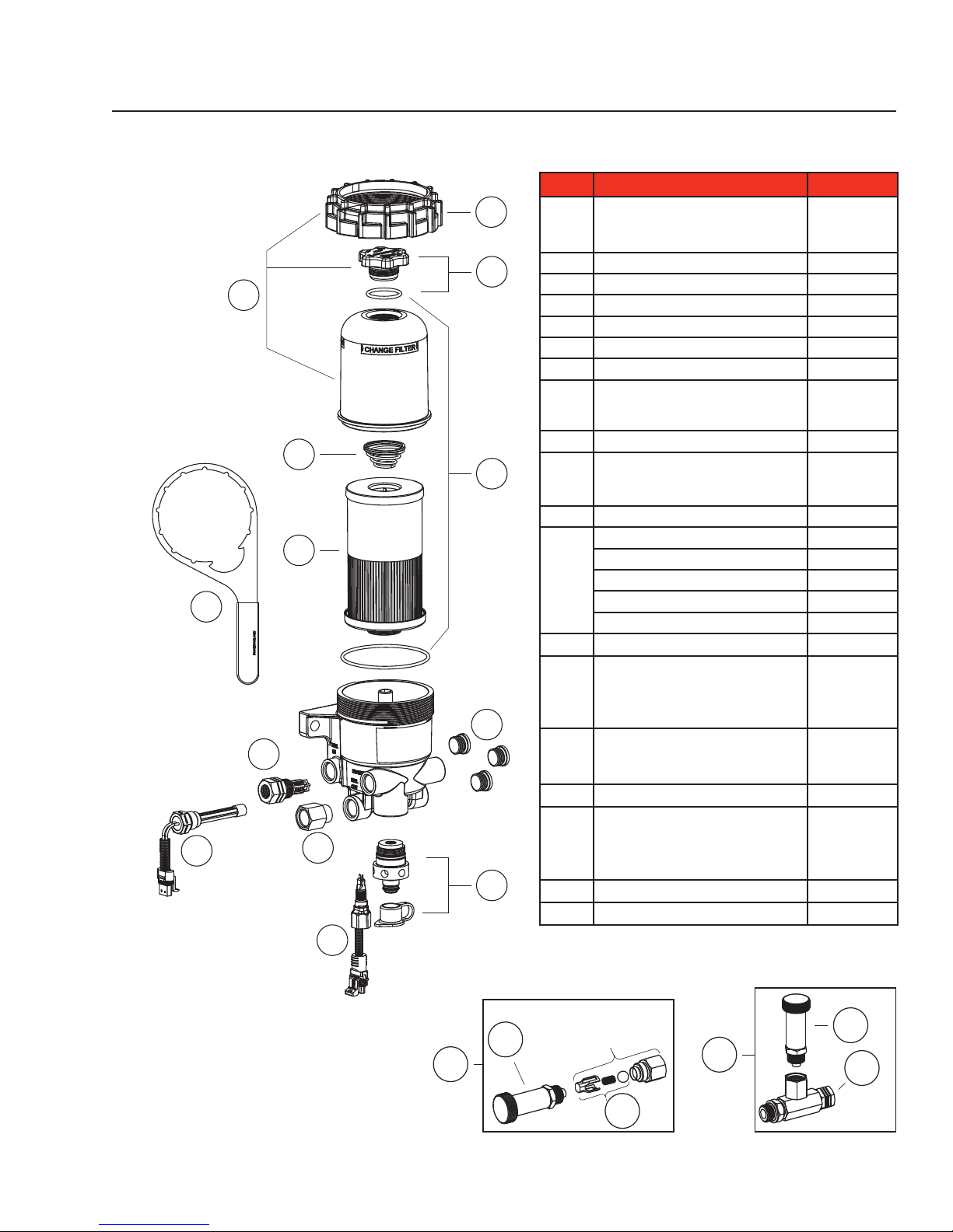
FH241 Cover
Assembly
Includes
Vent Cap,
Vent Cap O-Ring,
Collar, Cover,
Cover O-Ring,
and Spring
R
J
page 3
Parts ListDiesel Pro® 241
Part Description Part Number
F
D
A
E
B
C
Shown
G
M
H
I
FH241Cover Assembly includes Vent
Cap, O-Ring, Collar, Cover, Cover O-Ring,
A
and Spring)
O-Ring Pack – (Vent Cap and Collar)
B
Filter Element See page 9
C
Vent Cap Service Kit
D
Filter Spring
E
Reduced Clearance Collar
F
Diesel Pro® FH241, Unheated See page 13
G
Adapter - 7/8" to M16
Adapter - 7/8" to M18
H
Adapter - 7/8" to 3/8"
Drain & Cap
I
Pre-Heater, 24V, 195 W, Tyco Connector
Pre-Heater, 24V, 195 W, WP Connector
J
Over Night Heater, 120 V
Water-In-Fuel (WIF) Sensor
K
WIF Wiring Harness
WIF LED
Not
ESOC/Drain Valve
Drain Valve Service Kit
WIF Port Plug
Manual Primer Pump Pump
L
Primer Pump Check Valve (M16)
Primer Pump Check Valve (M18)
M
Primer Pump Check Valve (3/8")
Primer Pump Check Valve (7/8")
Primer Pump Service Kit (M16)
Primer Pump Service Kit (M18)
N
Primer Pump Service Kit (3/8")
Primer Pump Service Kit
O
Check Valve Assembly (M18)
Check Valve Assembly (M16)
P
Check Valve Assembly (7/8")
Check Valve Assembly (3/8")
Check Valve Service Kit
Q
Collar Wrench, Metal
R
3974145 S
3945061 S
SP1053
3944441 S
3945059 S
3973689 S
SP1643
3980209 S
SP1647
SP1314
SP1313
3945121 S
3957158 S
3950729 S
3946670 S
SP1645
SP1646
SP1125
3975110 S
3981659 S
3981660 S
SP1642
3975109 S
3979203 S
3979202 S
SP1632
3975111 S
SP72127
SP72128
SP72129
SP72130
SP1644
3944458 S
K
Manual Primer Pumps
L
L
O
N
P
Q
page 4
Introduction
How It Works
• Fuel from the tank enters the Diesel Pro® body
(suction side of the fuel system).
• Large contaminants and “free” water are
separated from the fuel and remain in the
body.
• Fuel rises into the clear cover.
• Contaminants and emulsified water are
captured by the filter media.
• Fuel level rises to maintain a fuel path
through the clean filter media and with lowest
restriction.
• Clean, water-free fuel exits the Diesel Pro and
flows to the lift pump.
“Seeing Is Believing”
• See when NOT to change the fuel filter.
• See the condition of the fuel. Seeing
what collects on the filter media or what’s
happening inside the clear cover can
help diagnose many fuel and mechanical
conditions.
• “Filter on Top” configuration. Water and
debris removed from the fuel falls to the lower
chamber and stays away from the filter media
resulting in longer filter life.
• Built-in protection when priming the fuel filter.
Unfiltered fuel is kept on the “dirty” side of the
filter media during priming ensuring only clean
fuel reaches the engine.
• Patented media. The “Best in Class”
StrataPore™ media removes 95% of free
and emulsified water. This performance far
exceeds that of cellulose media.
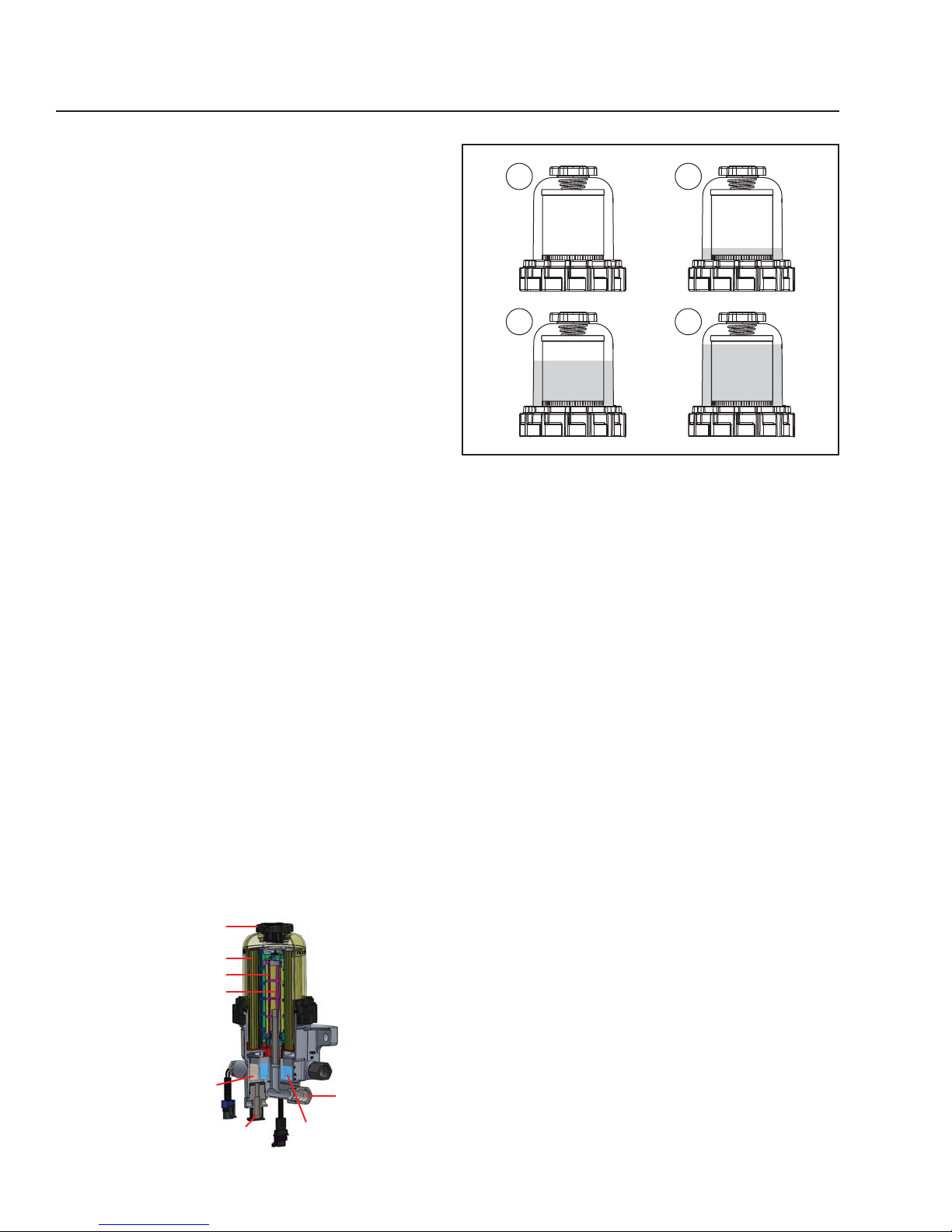
1 2
3 4
Figure 1 - “Seeing Is Believing”
1. When new, the fuel level in the filter will be
very low with minimal restriction. As the filter
is used, contaminants collect on the filter from
the bottom up. Fuel rises on the filter indicating
remaining filter life.
2. Fuel level increases in clear cover. As
contaminants collect on the filter, the fuel rises
to a non-contaminated section of the filter,
providing optimal filtration while maintaining
lowest restriction.
3. Fuel level at filter wrap level. Even though
the fuel level is now more than half of the filter
element, the fuel is still flowing through clean
media at minimal restriction levels. The filter still
has significant life remaining.
4. The filter element is now completely covered
by fuel. At this point, all of the media’s surface
area is utilized. Restriction is increasing and the
filter element should be changed at the next
scheduled maintenance interval.
Vent Cap
Media
Coalescent Layer
Hydrophobic Layer
Water Sump
Dirty Side
Drain Valve
(ESOC Compatible)
Water Sump
Clean Side
Fuel OUT
FH241 Series Advanced Water Separation
Architecture
The FH241 Series has a new water separation
architecture providing higher water separation
performance than the FH235 or FH236 series. The
FS20081 cartridge has additional coalescing and
hydrophobic layers that provide the performance
required for T4F and EPA2017 midrange engines.
The new water separation concept introduces two
additional steps (coalescing on an additional layer,
repelling on a hydrophobic layer), improving overall
water separation performance.

page 5
Service Kit Installation
This system must be installed between the fuel
tank and the transfer fuel pump. If approved by the
manufacturer, this system can be used as the only
fuel filter in the fuel system by removing the existing
filter and heads, or by removing the filters only and
replacing them with special Diverter Caps (sold
separately - see Table 1).
®
Note: If the Diesel Pro
is used as the primary filter
and a secondary filter is required, secondary
filter life may be extended.
Table 1 - Diverter Caps
Diverter Cap
Part Number
3945182 S
3945183 S
3945184 S
3945185 S
3945186 S
Required Filter
Head Stud Size
1"-14 2.475 (62.865) 2.895 (73.533)
1"-14 3.225 (81.915) 3.435 (87.249)
M16 x 1.5 2.475 (62.865) 2.895 (73.533)
3/4" x 16 2.475 (62.865) 2.895 (73.533)
7/8" x 14 2.475 (62.865) 2.895 (73.533)
Required Filter
Head Seal ID
in (mm)
Required Filter
Head Seal OD
in (mm)
WARNING: When diesel fuel is circulated
through an operating engine, it
can become very hot. To prevent
personal injury:
Scalding hazard! Do not allow heated
liquid fuel to come in contact with eyes or
unprotected skin. Always allow the engine
and fuel to cool to ambient temperature
before replacing the fuel filter or performing
service operations which could result in the
spillage of fuel from the fuel system. If this is
not possible, protective clothing (face shield,
insulated hat, gloves, apron) must be worn.
Fire hazard! Heated diesel fuel can form
combustible vapor mixtures in the area
around the fuel source. To eliminate the
potential for fire, keep open flames, sparks
or other potential ignition sources away from
the work area, and do not smoke during filter
replacement or service operations which
could result in the escape of diesel fuel or
fuel vapors.
Inhalation hazard! Always perform engine
or vessel fuel system maintenance in a
well ventilated area that is kept free of
bystanders.
The ignition key must be in the OFF position.
Installing the Diesel Pro Service Kit
1. With the engine shut down and at ambient
temperature, close the fuel shutoff valve (if
equipped) and place a suitable container under
the fuel filters.
2. Remove the primary fuel filter element assembly,
sedimenter, and/or water separator. Drain
the used element and dispose of it in an
environmentally responsible manner, according
to state and/or federal (EPA) or national
recommendations. The fuel can be returned to
the tank.
3. For a one-filter system, select the required
secondary filter head diverter cap from those
listed in Table 1. The required part number is
determined by the size of the spin-on filter stud
and the filter sealing surface diameter.
Install the diverter cap on the secondary filter
head as follows:
a. Remove the secondary fuel filter element,
drain and dispose of it in an environmentally
responsible manner according to government
regulations (i.e., state/province, federal, etc.).
The fuel can be returned to the tank.
b. Lightly lubricate the seal on the top of the
diverter cap with clean engine oil.
c. Thread the adapter onto the secondary filter
stud and tighten by hand only.
d. Install the "Do Not Remove" sticker on the
diverter cap.
4. Mount the Diesel Pro in the desired location
using 3/8" (9.5 mm) Grade 8 hardware. Keep the
following points in mind:
a. Mounting the Diesel Pro directly on the
engine is NOT RECOMMENDED.
b. Mount vertically with the cover and element
pointing up.
c. Make sure there is enough top and side
clearance for the cover to be conveniently
removed for filter replacement
(1.5" (38.1 mm) minimum).
d. Bolt spacing is 5.25" (133.35 mm).
CAUTION: The Diesel Pro
so that the Filter Element is above
the "FULL" level of the fuel tank.
If mounted below full tank level,
a shut off valve will be required
at the inlet to allow filter changes
without overflow of fuel.
®
MUST be installed
 Loading...