

Fleetguard CV50203, CV50204, CV50205 Installation Instructions Manual
Fleetguard® Open
Crankcase Ventilation (OCV) Kit
Installation Instructions
Installation Instructions for:
CV50203 301-400 HP Applications
CV50204 401-425 HP Applications
CV50205 526-640 HP Applications
CC
DD
EE
GG
JJ1 JJ2
BB
HH
AA
FF
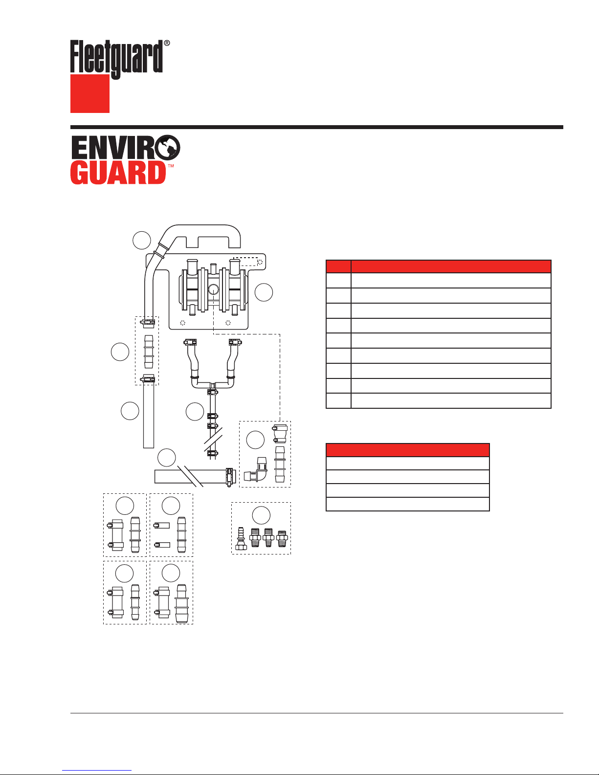
Parts List
Part Description
Breather Assembly (CV Unit) and Bracket
AA
Drain Hose Assembly
BB
Vent Hose
CC
Vent Hose Connector and Clamps
DD
Vent Hose Extender
EE
Cylinder Block Insert Fittings and Coupler
FF
Inlet Hose Assembly
GG
Breather (CV Unit) Hose Connections and Clamps
HH
Inlet Hose Connections and Clamps
JJ
Tools Required
Description
Hose Clamp Pliers
Hose Cutter
3/8" to 1" Ratchet and Socket Set
3/8" to 1" Wrench Set
JJ3
JJ4
E CAUTION: These instructions are intended for use by professional mechanics who are trained in the proper
use of power and hand tools, using appropriate safety precautions (including eye protection).
E CAUTION: Use of this application will
cause an increase in the engine
crankcase pressure. The installer
is responsible for the verification
that this application is appropriate
and that related crankcase
pressure issues do not arise.

page 2
Crankcase Ventilation Kit Installation
Preinstallation
The Fleetguard® OCV Kit can be installed on many
different engine platforms. Since engine design
varies broadly, connection and fitting sizes will
also vary by engine. To accommodate a broad
range of applications, the kit includes extra fittings,
connectors, clamps, and hoses. These parts
have been packaged in different packs to assist
you in choosing the right parts for your specific
application. Since many of these parts appear to
be very similar, we strongly suggest not opening
the individual packs until you have determined
what specific parts you will need for your engine
application. Each pack is identified with a label
(JJ1, JJ2, for example) to reference its use in the
appropriate installation step.
In some engine applications, the crankcase drain
fitting for connecting and routing the drain line to
the crankcase may need to be purchased from the
engine manufacturer. We strongly suggest not
drilling into the engine block or oil pan to use
one of the fittings included in this kit. Check to
determine if one of the fittings included in pack
“F” can properly be installed in the engine block
before proceeding.
To install the Enviroguard OCV system on engine
platforms with dual breathers, an additional
Enviroguard component kit must be used. This kit
includes an additional inlet hose, a Tee connector
and clamps. This kit allows you to fully adapt
all Enviroguard systems to dual breather engine
designs. The kit is part # 394316000S.
“Hot” (Exhaust Manifold) Side
“Cold” Side
Threaded
Boss
Figure 1 – Mounting Location
2. Find a mounting location for the breather
assembly and bracket at least 14" (350mm)
above the oil level in the crankcase. The
assembly must be a minimum of 4" (100 mm)
from both the exhaust manifold and exhaust
system components.
“Cold” Side
AA
Breather/Bracket
Assembly
14"
(350 mm)
Locating and Mounting the Breather Assembly
1. Check both sides of the cylinder block to
determine the most suitable oil return options.
Unused threaded bosses are usually located
on each side of the engine just above the oil
pan rail. Once the unused bosses are located,
determine the best location for mounting the
breather assembly to ensure the drain hose will
run directly to the crankcase when installed.
It is preferable to use a threaded boss on the
“cold” side of the engine opposite the exhaust
manifold. The drain hose must be free of any
loops, kinks or abrupt bends to ensure proper
oil drainage.
Figure 2 – Installing the Breather/Bracket Assembly
3. The “cold” side of the engine is the preferred
location for mounting. The breather assembly
must be mounted vertically (as shown in
Figure2) for proper operation.
4. Attach the bracket to the mounting location
selected. When the bracket position has been
determined, reverify the breather assembly is
mounted vertically with the oil drain outlets
directed downward.
 Loading...