

Fleetguard CV50108, CV50109, CV50110, CV50111, CV50112 Installation Instructions Manual
A
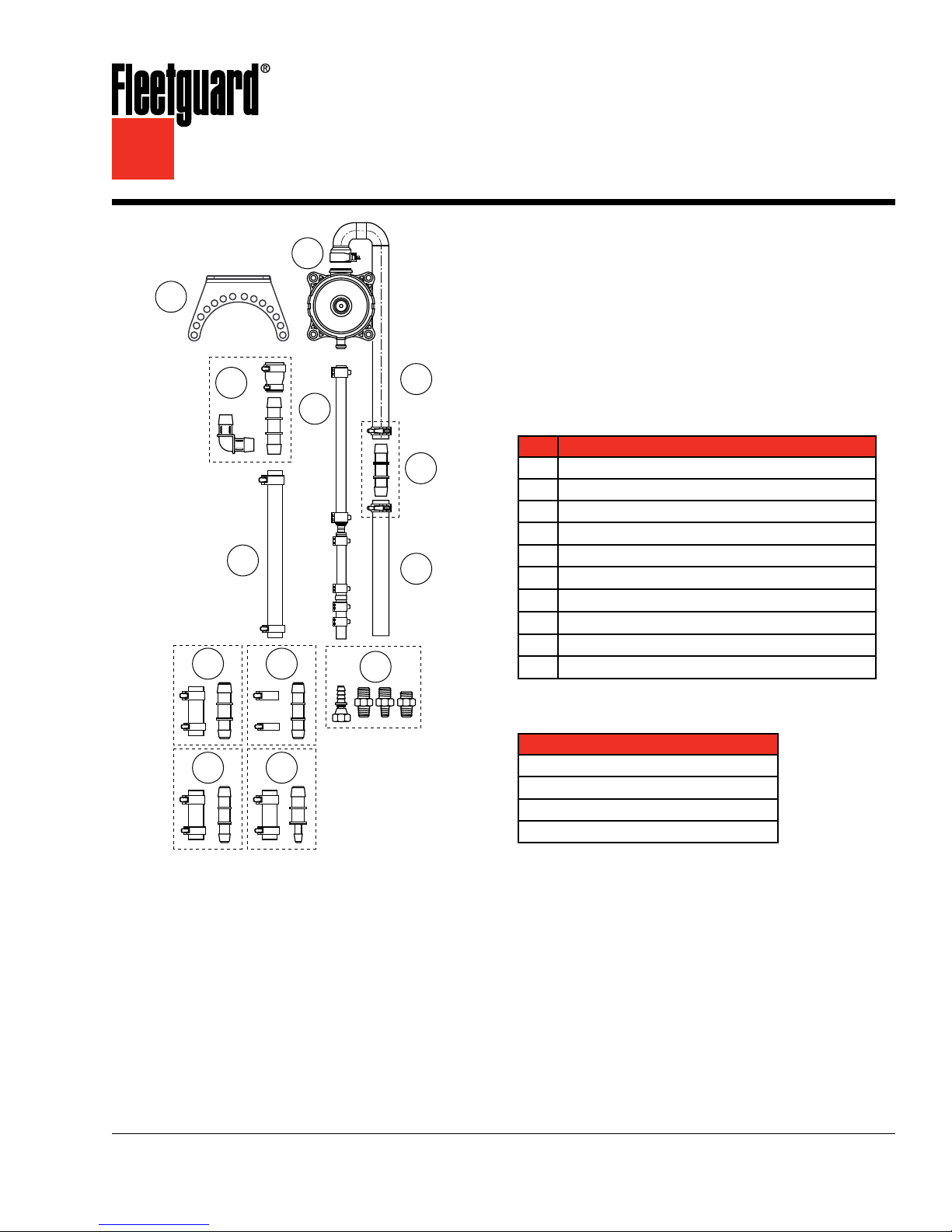
J1 J2
H
Fleetguard® Open
Crankcase Ventilation (OCV) Kit
Installation Instructions
Installation Instructions for:
B
C
G
D
I
E
F
CV50108 60-90 HP Applications
CV50109 91-120 HP Applications
CV50110 121-160 HP Applications
CV50111 161-220 HP Applications
CV50112 221-300 HP Applications
Parts List
Part Description
A
Mounting Bracket (not included in the kit)
B
Breather Assembly (CV Unit) and Mounting Hardware
C
Vent Hose
D
Vent Hose Connector and Clamps
E
Vent Hose Extender
F
Cylinder Block Insert Fittings and Coupler
G
Drain Hose Assembly
H
Breather (CV Unit) Hose Connections and Clamps
I
Inlet Hose Assembly
J
Inlet Hose Connections and Clamps
Tools Required
Description
J3 J4
Hose Clamp Pliers
Hose Cutter
3/8" to 1" Ratchet and Socket Set
3/8" to 1" Wrench Set
E CAUTION: Use of this application will
cause an increase in the engine
crankcase pressure. The installer
is responsible for the verification
that this application is appropriate
and that related crankcase
pressure issues do not arise.
E CAUTION: These instructions are intended for use by professional mechanics who are trained in the proper
use of power and hand tools, using appropriate safety precautions (including eye protection).

page 2
Crankcase Ventilation Kit Installation
Preinstallation
The Fleetguard® OCV Kit can be installed on many
different engine platforms. Since engine design
varies broadly, connection and fitting sizes will also
vary by engine. To accommodate a broad range of
applications, the kit includes extra fittings, connectors,
clamps, and hoses. These parts have been packaged
in different packs to assist you in choosing the right
parts for your specific application. Since many of
these parts appear to be very similar, we strongly
suggest not opening the individual packs until you
have determined what specific parts you will need
for your engine application. Each pack is identified
with a label (e.g. J1, J2) to reference its use in the
appropriate installation step.
In some engine applications, the crankcase drain
fitting for connecting and routing the drain line to
the crankcase may need to be purchased from the
engine manufacturer. We strongly suggest not drilling
into the engine block or oil pan to use one of the
fittings included in this kit. Check to determine if one
of the fittings included in pack “F” can properly be
installed in the engine block before proceeding.
14"
Figure 1 – Mounting Location
3. Install the mounting bracket (if used) to the
mounting location selected. The mounting bracket
can be attached to the breather assembly at four
different positions by simply rotating the bracket.
Attach the breather assembly to the bracket using
the hardware provided. Ensure that the breather
assembly is mounted vertically with the oil drain
outlet directed downward.
A
Locating and Mounting the Breather Assembly
1. Check both sides of the cylinder block to
determine the most suitable oil return option.
Select a threaded boss or another entry option
that will allow the drain hose, when installed, to
run directly from the breather assembly to the
crankcase. The drain hose must be free of any
loops, kinks or abrupt bends to ensure proper oil
drainage.
2. Find a mounting location for the breather
assembly and bracket at least 14" (350 mm)
above the oil level in the crankcase and a
minimum of 4" (102 mm) from both the exhaust
manifold and exhaust piping. The “cold side” of
the engine is preferred. The breather assembly
must be mounted vertically (as shown) for proper
operation.
B
Figure 2 – Installing the Mounting Bracket Installing
the Insert Fitting
4. Locate the selected threaded boss at the bottom
of the cylinder block (above the pan rail) for
installation of the cylinder block insert fitting.
Check the boss opening ID to determine if any of
the fittings included in the "F" pack can be used.
If none of the fittings can be used, check with the
engine manufacturer on the proper insert fitting
to gain access to the crankcase. Once the proper
crankcase fitting has been selected, proceed with
Step 5.
 Loading...