

Fleetguard Centriguard CH41111, Centriguard CH41113, Centriguard CH41114, Centriguard CH41112 Installation Instructions Manual
Centriguard™
E
D
B
A
C
Centrifugal Separator
INSTALLATION
INSTRUCTIONS FOR
CH41111, CH41112,
CH41113 AND CH41114
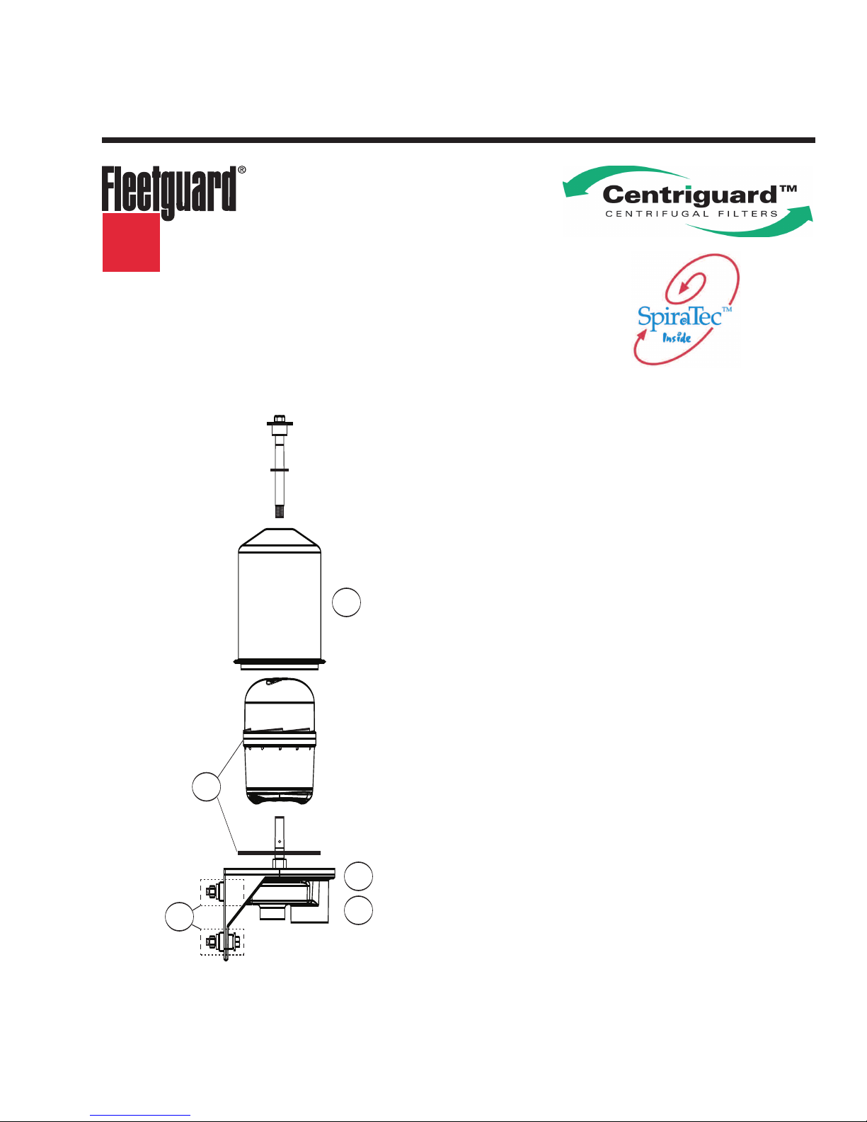
Component Parts
A. Vibration Isolator Kit (4 vibration
isolators, 4 bolts, 8 washers, and
4 nuts)
B. Gravity Drain Base Casting and
Shaft for CH41111 and CH41113
C. Air Assist Base Casting and Shaft
for CH41112 and CH41114
D. Service Rotor and Gasket
E. Housing Assembly
CAUTION: These instructions are intended for use by
essional mec
of
pr
use of power and hand tools, using appropriate safety
precautions (inc
hanics who are trained in the proper
luding e
ye protection).
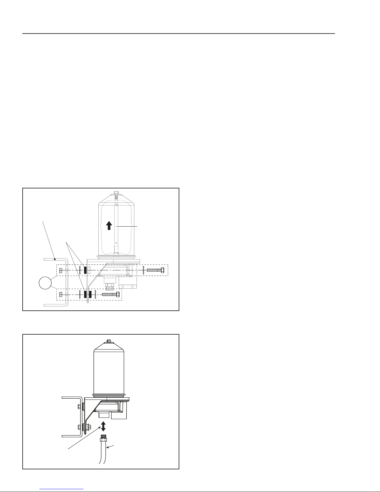
Steps 1 and 2
Vibration
Isolators
Shaft
Pointed
Upwards
Frame Rail /
Mounting Bracket
A
Step 3
Minimum 1/2" (12.7 mm)
ID Hose (#8 or #10)
CH41111 or CH41113
Centrifugal
Separator
(Gravity Drain)
M22 x 1.5 O-Ring
Connection Fitting
page 2
Installation Steps
Pre-installation Notes
CAUTION: Engine oil, components and surfaces may be hot.
The CH41111, CH41112, CH41113 and CH41114 separators are bypass filtration devices. All current full-flow
filters on your engine or system should remain as they are.If a separate bypass filter is also on the engine,
this unit will need to be removed and its connection plugged.If a combination full-flow/bypass filter exists on
the engine, then it must be confirmed that the bypass section of the combo filter empties into the main oil flow,
not directed back to the sump.If the bypass flow of the combination filter is directed back to the sump, contact
your Fleetguard representative for support. If the engine does not have a bypass filter already, and the
CH41111, CH41112, CH41113, or CH41114 is being added to the system, check the engine oil flow and
pressure requirements to make sure the addition of this unit is within the acceptable limits.
Examine the separator for any shipping damage and determine the best location for installing the separator
assembly. Depending on the application, this location may be on the frame rail, on the engine or the
equipment being used.
Turn the engine off before starting the installation process.
Mounting the Separator
Step 1 - Place the separator where it is to be
mounted. It is shipped with the vibration isolators
installed. Use of the vibration isolators is
recommended to reduce vibration noise.
Important:The base casting must be
mounted with the shaft pointed upwards
(± 10 degrees).
Step 2 - Insert the bolts and w
in the illustration and secure with the nuts.
Tighten to 20
If you are installing a CH41112 or CH41114
separator, skip to Step 5.
ft-lb (26.5 N·m).
ashers as shown
Installing the Oil Inlet Line on a CH41111
or CH41113
ailable oil supply port on the engine for
Use an a
the separator inlet connection. Most engines
provide a port to supply auxiliary devices.
Step 3 - Connect the inlet line to the smaller of
the two ports at the bottom of the unit with an
M22 x 1.5 o-r
line m
(#8 or #10 hose).Tighten to a maximum
22 ft-lb (30 N·m).
v
ing connection fitting.
ust be at least 1⁄2" (12.7 mm) ID hose
The inlet
 Loading...