

Page 1
MGS200 Installation Guide:
MGS200 Installation Guide Feb, 10
Condential Version 1.4
1. Contents
2. Tools / Materials required
2. Work order / System outline
2. Hardware location and preparation
3. Antenna location
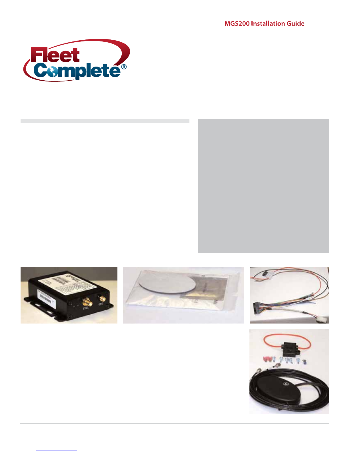
Contents:
1. MGS200-G
2. Antenna pad
3. 20 pin cable
4. Antenna
3. MGS mounting
4. Power wire installation
5. Wire connections
& fusing
6. Installation diagram
1. 2. 3.
6.
8. 7. 5.
5. Blue ring terminal (gound connector)
6. Fuse holder
7. Amp fuse
8. Plated steel screws
4.
Page 2
MGS200 Installation Guide Feb, 10
Condential Version 1.4
Page 02
Tools Required:
1. Full compliment of various screw
drivers
2. Crimping tool for crimp connectors
3. Wire cutters and strippers
4. Ring, spade, splice crimp connectors
(red and blue)
5. Small spools of red and black 16
gauge wire
6. Digital multimeter
7. 7” black cable ties
8. Silicone
9. Soldering iron and solder
Work order/system outline:
Hardware location and preparation:
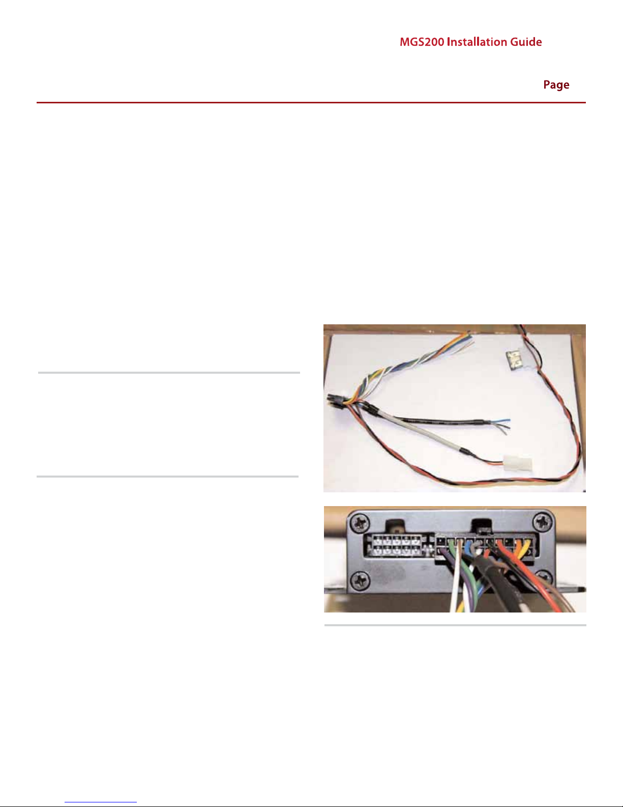
Note: It is important to insulate the wires not being used on
the wire harness during the installation. Improper insulation
could result in inaccurate notications and increased usage on
monthly billing.
•
Find a suitable location for the MGS if one has not been
specied on the work order. The MGS is usually installed
under the vehicle’s dash.
Keep the device away from any places of high moisture i.e.
•
under seats, oors, etc.
Prepare all connections for the MGS, cable harness and
•
fuse holder prior to commencing installation.
Verify the requirements of the installation as described in
the work order
Special instructions should be outlined on the work order
Page 3
MGS200 Installation Guide Feb, 10
Condential Version 1.4
Page 03
Antenna location:
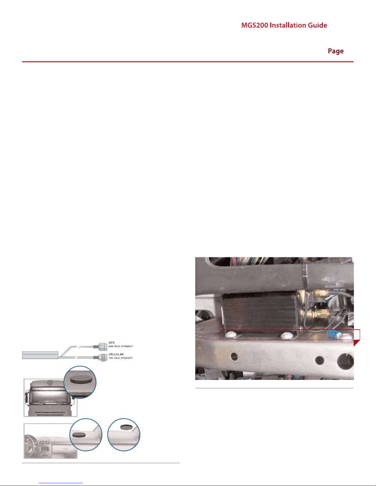
Note: The GPS/RF Combo antenna must be mounted at with
the GPS Receiver facing up (The letter “H” is facing up). The
ideal location is on the roof; however the antenna can be
installed on the dashboard or on the window. If the vehicle
window has a solid dark coating around the edge, do not place
the GPS antenna behind the coating. The GPS signals will travel
through the clear glass but will be reduced if the window has
any metallic coating or tint applied.
The GPS/RF Combo antenna will work best if it has a clear view
to the sky and as much of the horizon as possible. Any metallic
objects between the antenna and the GPS satellites will
degrade the signal and reduce the overall performance.
Antenna can be roof, dash or window mounted.
•
Find a location on the vehicle with a clear line of sight to
the sky and place the antenna on the roof/dash/window.
For dash or window mounting, to keep the wires hidden,
•
run the wires behind the dash.
•
For roof installation, run the wires into the vehicle in the
best possible way to keep the wires from being pinched.
Keep the wires tight to prevent them from slapping on the
vehicle when in motion.
MGS mounting:
Note: The unit should be mounted so it will not be exposed to
damage from people or objects. The cables that connect to the
unit should also be routed to protect them from possible damage. The MGS has a ange with four mounting holes. Normal
installation is with these four holes and #6 or #8 sheet metal
screws. The unit must be mounted where it will not be exposed
to direct sunlight or excessive heat generated by the vehicle
operation. Some examples of mounting locations include under the dash above the knee bolster, under the center console,
behind the glove compartment, and in the trunk.
•
The MGS is equipped with slotted anges to mount on at
surfaces with #8 sheet metal screws.
•
If a at surface cannot be found in the desired location, it
is possible to mount the MGS using 4 cable ties around an
object under the dash. ONLY USE THIS AS A LAST RESORT!
•
Ensure the MGS cannot vibrate excessively and is protected from all elements.
•
If needed, drill a small pilot hole from the inside of the vehicle out. Remove the nut from the antenna and feed the
wire through the hole. Place a bead of silicone around the
stem of the antenna. From inside, use the nut and lock
washer to tighten the antenna to the roof. Place a small
bead of silicone where the antenna and roof meet.
Run the antenna wires to the MGS location as you see t.
•
Page 4
Power wire installation:
MGS200 Installation Guide Feb, 10
Condential Version 1.4
Page 04
The MGS is connected directly to the vehicle’s 12-volt system.
There is no on-o switch on the unit. The installed unit operates 24 hours a day and must be powered to log vehicle events
or send data as required by the client.
The MGS is shipped with one in-line 3-amp fuse attached to
the power cable. This fuse must be installed as close as possible
to the primary 12-volt source connection. The fuse protects the
power cable should there be a short in the cable between the
fuse and the MGS. This fuse must be installed properly. If the
fuse is replaced, it should be of the same type as originally
supplied from the factory. Failure to use the proper fuse or to
install the fuse in the recommended location could cause a
vehicle re hazard. The fuse provides overload protection for
the power cable and MGS. The wiring installed between the
fuse and primary vehicle power is not protected from overheating if a short should occur. Use care when routing the
power cable and fuse. Route the cables where they will be protected and uses include commonly accepted install practices
for after market automotive electronic devices.
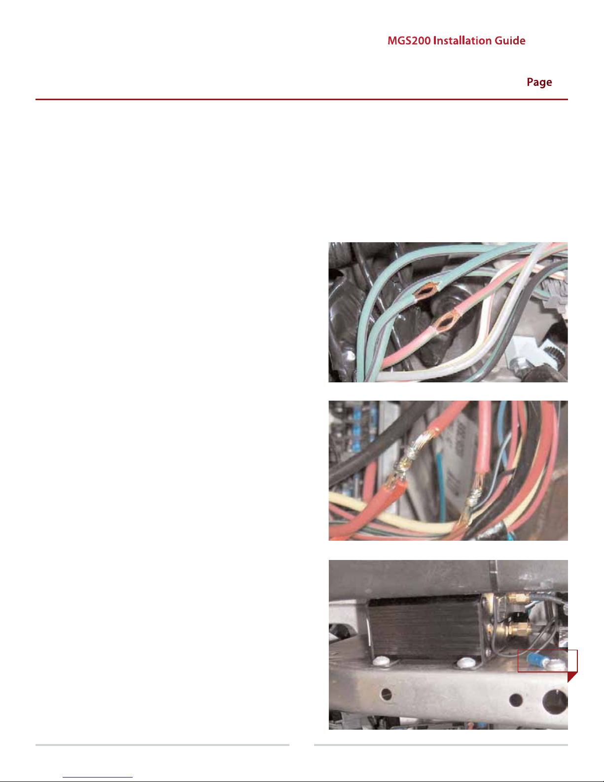
There are two acceptable methods of making a wire
connection:
•
Soldering your connections (recommended)
•
Splice the other side of the fuse holder to the power wire
identied in the vehicle with solder or crimp terminal.
Run the ignition switch input (brown) wire to the primary
•
ignition wire in the vehicle. Locate the appropriate wire
under the dash. When the ignition key is turned to the “On
or Run” position, this will show +12 Volts DC.
•
Crimp connectors (with the use of the proper crimping
tool)
Regardless of the method you choose, ensure that connection
is mechanically sound and properly insulated. Use high quality
electrical tape or shrink tubing, cheap tape will unravel in hot
weather making it a poor insulator.
Never use “t-tap” connectors (poor quality mechanical type
connection).
Never “twist and tape” without soldering your connection.
•
Extend the power wires on the MGS using splice crimp terminals and your RED and BLACK 16 gauge Wire.
•
Run the ground (black) wire to a suitable chassis ground
by using the crimp ring terminal.
•
Run the positive (red) wire to the constant power (+12
volts DC at all times) and splice an inline fuse holder to the
end. This is to protect the wire run.
Page 5
MGS200 Installation Guide Feb, 10
Condential Version 1.4
Page 05
Red LED Description
OFF
1 – 1
2 – 1
2 – 2
2 – 3
2 – 4
3 – 1
3 – 2
3 – 3
3 – 4
3 – 5
No faults detected
License Key Exp.
CDMA Module fault
Not Activated
No CDMA Signal
Network not found
GPS Module fault
GPS Annt. Open/Short
GPS Not track (0 Sat.)
GPS No x (<3 Sat.)
GPS No time
Green LED Description
OFF
Flash
Slow
Fast
Power Down mode
Low power mode
Full power ignition O
Full power ignition On
Conrming proper operation:
•
Connect the antenna cables to the appropriate locations
on the MGS.
•
Check the power light on the MGS
Check for cellular connectivity light (Flushing Blue).
•
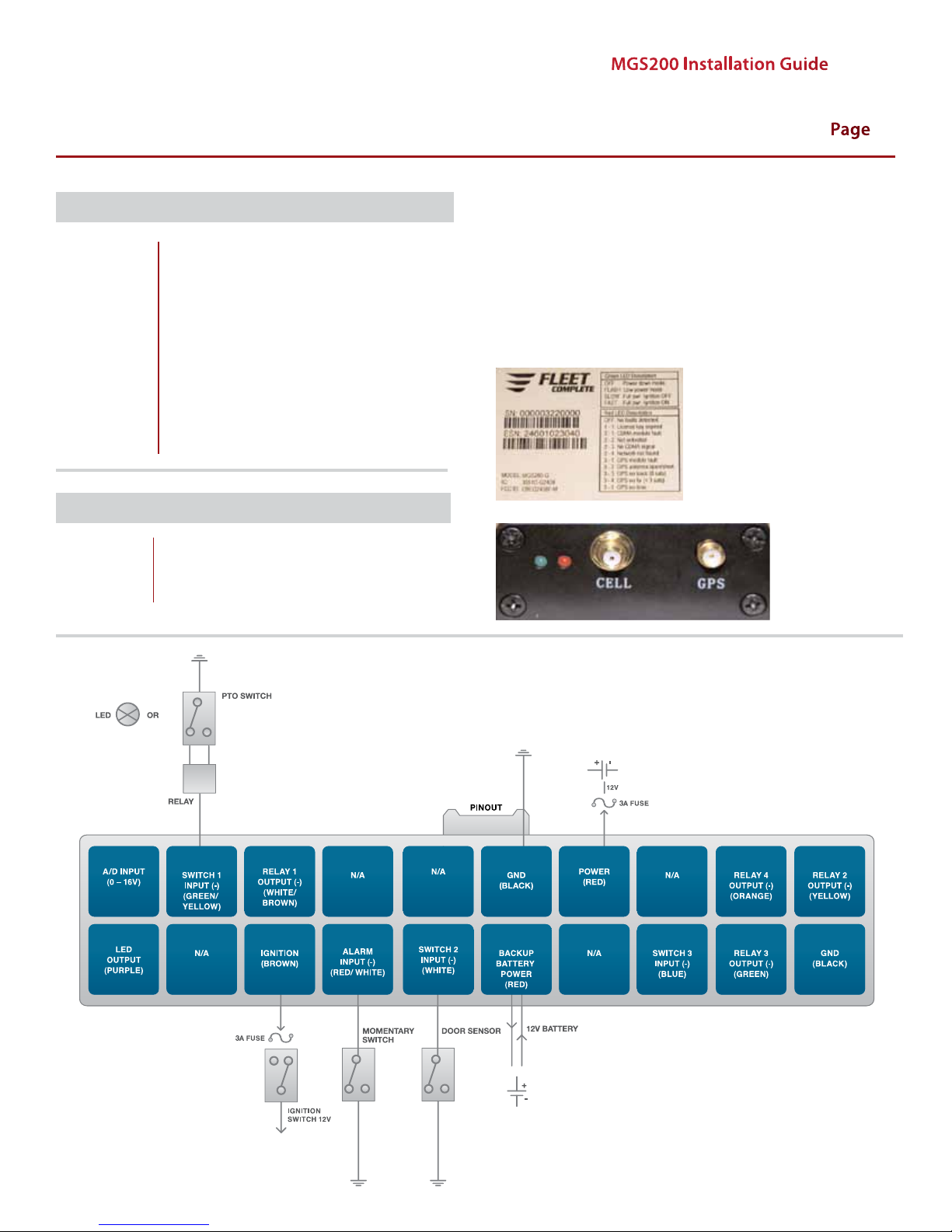
MGS 200-G INPUT INSTALLATION DIAGRAM
Applies to Serial #
000003259999 ( - )
Page 6
MGS200 Installation Guide Feb, 10
Condential Version 1.4
Page 06
TeMPeRATURe PRObe
1 wIRe
DATA
When the ignition is rst turned on the MGS200 will power-up. The
Green LED will show solid for approximately 30 seconds. At no other
time should be green LED remain on solid for such a long period.
After 30 seconds the green LED will start to ash at the following rates:
25 times on-o every 10 seconds when the ignition is on
•
(this is quite rapid)
•
8 times on-o every 10 seconds when the ignition is o
(this is quite slow)
•
Very short blip once every 3 seconds when in sleep mode
The green LED will also show if there is a active input by ashing a
number of times corresponding to the input (1,2,3,4). For example
if input 4-Alarm is active then there will be 4 short ashes every 3
seconds.
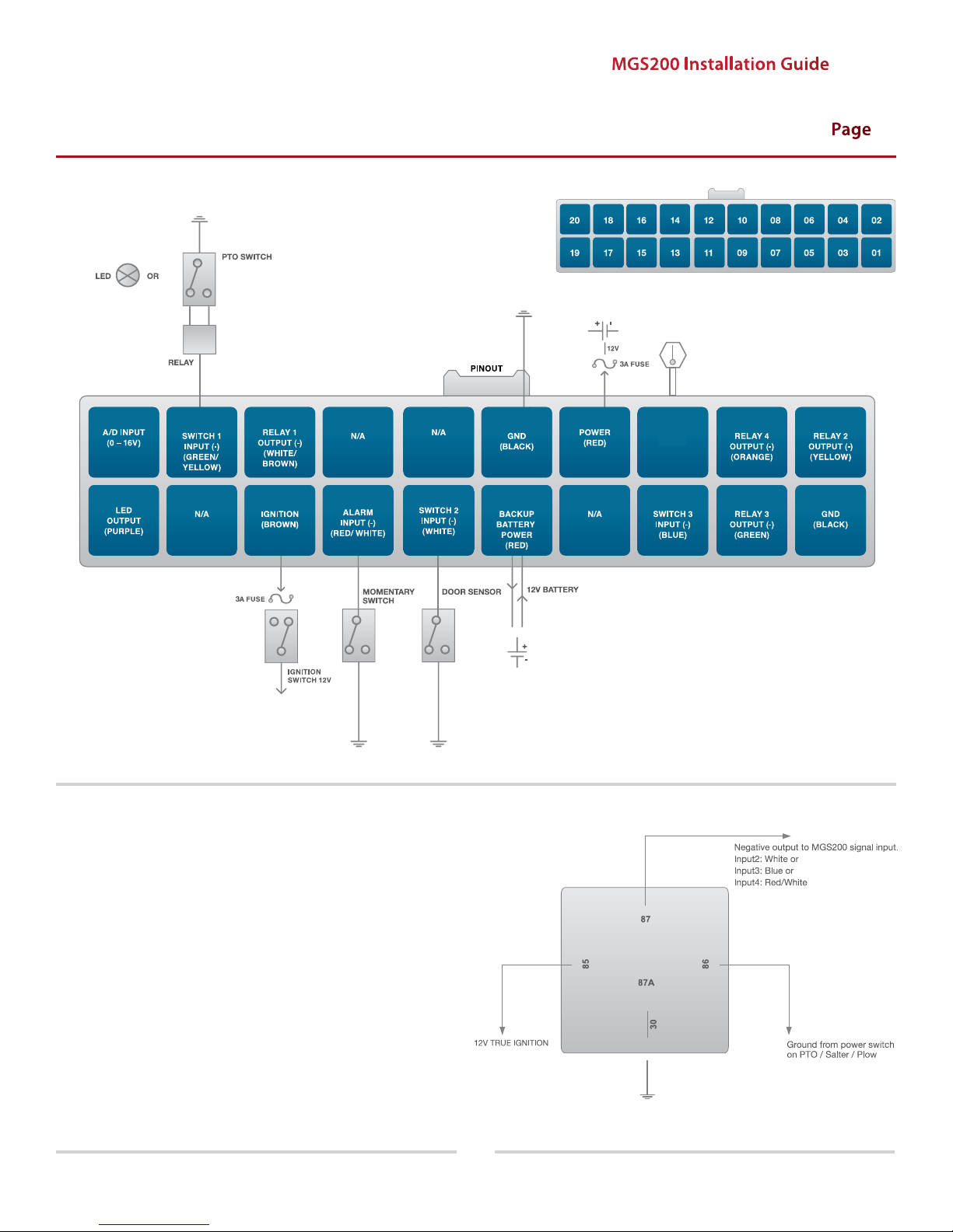
Applies to Serial #
000003260000 (+)
 Loading...