

Page 1
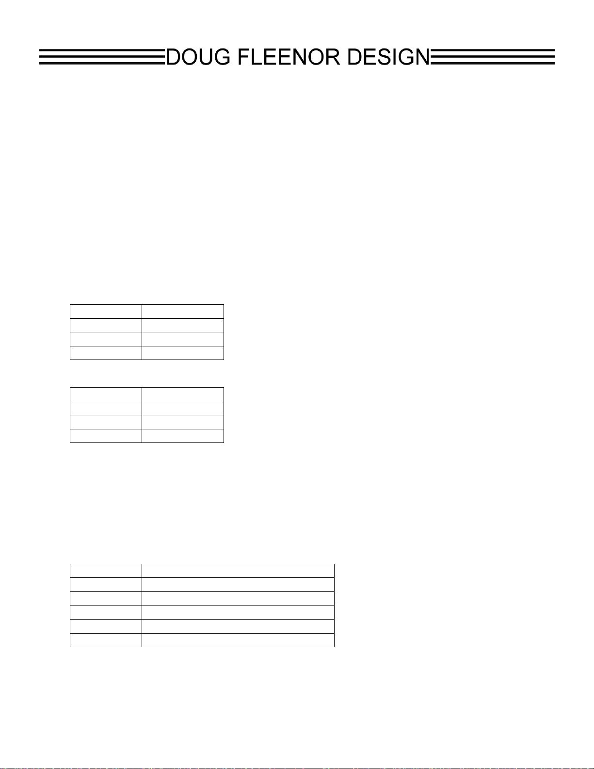
Pin Number
Function
2
Receive data
3
Transmit data
5
Common
Pin Number
Function
1
Common
2
Receive data
3
Transmit data
Pin Number
Funciton
1
Common
2
DMX data minus
3
DMX data plus
4
connected from input to output only
5
connected from input to output only
RS-232 to DMX512 Interface, 2nd Generation
model: 2322DMX
For Serial Numbers before 223148
The second generation RS-232 to DMX512 interface has numerous features beyond
the original device. The protocol described in this document supports the new features.
The protocol described for the original RS-232 to DMX512 interface is not supported by
this device. The changes required to move to the new interface are minimal and are
described later in this document.
Connections
The RS-232 signals are available on the front panel DB-9M connector and on the 3 pin
female XLR connector on the rear panel. Please connect to only one of these ports.
You may not use the two ports simultaneously.
The front panel DB-9M connector pinout is:
The rear panel 3 pin XLR connector pinout is:
The male and female 5 pin XLR connectors are in parallel. When the interface is
configured for mode zero (DMX output), only the female output connector should be
used. When the interface is configured for mode one (DMX input), the external DMX
source should be connected to the male input connector. The female output connector
can be used to connect to other DMX devices. If the female output “thru” connection is
not used, a 120 terminator should be connected.
The pinout for the 5 pin XLR connectors is:
Page 2

Indicators
The red POWER LED will illuminate when the interface is powered.
The green MIMIC LED has no function at this time
The green SIGNAL LED will flash when an RS-232 command is received while in mode
zero. While in mode one, the SIGNAL LED will turn on when DMX input is present.
Address switches
While in mode one, the address switches select a “channel of interest”. The interface
will report changes in level for the channel of interest in the standard level format
described in the protocol below.
Communication port settings
The RS-232 port is configured with the following settings:
Baud 9600
Start bits 1
Data bits 8
Parity None
Stop bits 1
No handshake signals are required or provided.
The RS-232 port is full duplex and the receiver has a 256 byte circular buffer.
If you are using a Windows computer, the comm port flow control must be set to None.
The FIFO buffers should be disabled.
Protocol
All commands are sent in plain ASCII format. Each command is terminated with a
carriage return <CR>. This is the character used by the interface to trigger any action.
The hexadecimal value for the <CR> is 0x0D.
After receiving a carriage return, the interface will respond with the characters received
followed by “OK” if the command was formatted and processed successfully. If there
was any syntax problem, the interface will respond with the characters received
including the error-causing character and “Error”.
Spaces between commands are optional. All letters can be either upper or lower case.
All channel numbers are in the range of 1-512. All channel levels are in decimal in the
range of 0-255. All preset numbers are in the range of 1-20. All times are in the range
of 0-999. Leading zeros are allowed and are optional. The total number of digits must
not be more than is allowed for the given parameter. For example, sending a preset
number as “005" will cause an error because only two digits are allowed in preset
numbers. Sending “05" as a preset number is acceptable. Similarly, a channel number
of “004" is OK while “0004" would cause an error.
Page 3
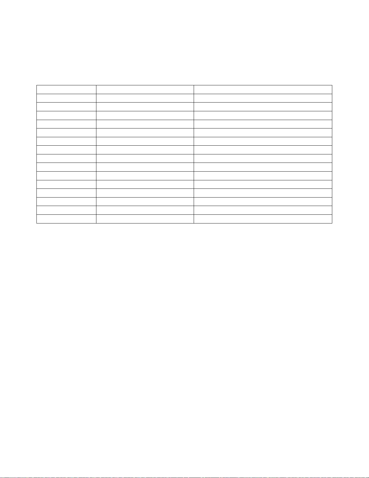
One special command is executed immediately without the <CR> terminator. Sending
ASCII character
Command
Parameters
C
Channel number
1-3 digit number (range 1-512)
F
Fade time for a preset
1-3 digit number (range 0-999)
H
Heartbeat (on/off)
1 digit (range 0-1)
L
Channel level
1-3 digit number (range 0-255)
M
Mode (DMX input/output)
1 digit (range 0-1)
P
Play preset
1-2 digit number (range 1-20)
R
Record preset
1-2 digit number (range 1-20)
S
Remote station support
1 digit (range 0-2)
T
Channel or preset fade time
1-3 digit number (range 0-999)
U
Update software
2 digit number (must be 42)
V
Version number
none
Z
Set all levels to zero
none
@
Channel level
1-3 digit number (range 0-255)
?
Query
1-3 digit number (range 0-512) or letter P
$
Reset interface
none
the ASCII dollar sign character ($) will cause the interface to immediately reset. This
feature was added as a fallback in case the input buffer becomes overrun. Any pending
actions are aborted when this character is received.
Setting a channel level
Commands relating to setting a single channel can be sent in a one packet with a
single carriage return at the end. The format for setting a channel to a level is:
C ### L ### <CR> or: C ### @ ### <CR>
For example, setting a channel to a level could be sent as:
C 15 L 255 <CR>
In this example, channel 15 would be set to a level of 255.
A time may also be assigned to the movement of a single channel. The format is:
C ### L ### T ### <CR>
For example:
C 15 L 45 T 5 <CR>
In this example, channel 15 would fade from its current level to a level of 45 in 5
seconds.
Note that multiple channels may not be moved within a single command. The channel
Page 4

command supports one channel move at a time.
The “@” character may be used instead of the “L” character to indicate the level for the
channel. This allows for a command such as:
C 15 @ 45 <CR>
Recording a preset
The RS-232 to DMX512 interface can record 20 different presets. Once levels have
been set using the channel command, those levels can be recorded in a preset for later
recall. The format for this command is:
R ## <CR>
For example:
R 5 <CR>
In this example, the current output levels will be recorded into preset 5.
A default time of 5 seconds is recorded with each preset. The time recorded with the
preset can be changed using the “F” (fade) command.
Note that a preset may be recorded from levels set by the interface while it is in mode
0. DMX levels from an outside source may be captured to a preset while the interface is
set to mode 1.
Playing a preset
The 20 presets can be recalled using the play preset command. The interface uses a
“radio button” action. When one preset is recalled, all output channels go to the
recorded levels for the new preset. Thus, only one preset is active at a time. Once the
preset is “live”, individual channels can be set to new levels to create new presets or to
modify the existing look. The format for playing a preset is:
P ## <CR>
For example:
P 5 <CR>
In this example, preset 5 will be recalled. The output will fade to the levels in preset 5 in
the fade time recorded with the preset.
The fade time for a preset can be temporarily overridden using the time parameter in
the preset recall command using the format:
Page 5

P ## T ### <CR>
For example:
P 10 T 8 <CR>
In this example, preset 10 will be recalled. The output will fade to the levels in preset
10 using an 8 second fade regardless of the fade time recorded with preset 10
originally. Note that this new fade time is temporary. To permanently change the fade
time for the preset, you must recall the preset and then re-record it with the new fade
time as shown in the “recording a preset” command.
Changing the fade time recorded with a preset
Each preset has a default fade time of 5 seconds. This is set when the preset is
recorded. The fade time associated with each preset can be changed so that when the
preset is played, its fade time is also recalled. The fade time command sets the time
for the last preset recalled. To set the time of a particular preset, recall that preset
using the play preset command and then set its time using the command format:
F ### <CR>
For example:
F 10 <CR>
In this example, the currently active preset’s fade time will be set to 10 seconds.
Clearing outgoing levels
The ‘Z’ (zero) command is used to set all DMX channels to 0. This is useful for clearing
all levels as a starting point to build a new preset. The format for the command is:
Z <CR>
Entering this command will immediately set all channels to zero. No time parameter is
allowed with this command.
Software version
The ‘V’ (version) command is used to view the installed software version number. The
format for the command is:
V <CR>
There are no parameters allowed with this command.
Setting the mode
The ‘M’ (mode) command is used to select whether the DMX port is set to transmit or
Page 6

receive. While in transmit mode (mode 0), the interface is the source of DMX like a
console.While in receive mode (mode 1), an external DMX source can be used to set up
looks. The RS-232 to DMX interface can record those looks into its presets and queries
can be used toretrieve the current incoming DMX levels. Mode 0 sets the interface to
transmit DMX.Mode 1 sets the interface to receive DMX. The format for the mode
command is:
M # <CR>
For example:
M 1 <CR>
In this example, the interface will be set to receive DMX.
The mode selection is stored in non-volatile memory and will be recalled on power up.
Query for information
The ‘?’ (query) command is used to request status information from the interface. The
current level of a specific channel can be requested. When the query number is in the
range of 1-512, this command will be triggered. The command format is:
? ### <CR>
For example:
? 451 <CR>
In this example, the interface would return the current level of channel 451 in the
format:
C451@??? <CR> (where ??? is the decimal level for the channel)
Sending a query for channel 0 will cause the interface to respond with the current levels
for all 512 DMX channels. For example:
? 0 <CR>
In this example, the interface would return the values for all channels in the format:
C001@???<CR> (where ??? is the value for the channel)
C002@???<CR>
...
...
C512@???<CR>
Page 7

Note that all channel level queries can be used to determine the level of DMX being
sent by the interface in mode 0 or of incoming DMX levels while in mode 1.
Sending a query for ‘P’ will cause the interface to respond with the currently active
preset. For example:
? P <CR>
Note that if a channel level has been changed after a preset has been recalled, the
preset number reported will be preset 0. This indicates that the levels are not
representative of any recorded preset.
In this example, the interface would return the number of the active preset in the format:
PRESET ## <CR>
Setting the heartbeat
The ‘H’ (heartbeat) command is used to select whether the heartbeat is on or off.
When enabled, a period “.” is sent from the interface every 1 second to allow a control
system to detect that the interface is connected. Setting the heartbeat equal to 1 turns
the feature on. Setting it to 0 (the default) turns the feature off. The format for this
command is:
H # <CR>
For example:
H 1 <CR>
In this example, the interface will start sending heartbeat characters.
The heartbeat selection is stored in non-volatile memory and will be recalled on power
up.
Setting the remote station support mode
The ‘S’ (remote station) command is used to select whether the interface will support a
Preset 10 remote station on the DMX port. When enabled, alternate start code packets
are sent from the interface and remote stations are allowed to reply to select presets.
The default value for this feature is 0 (disabled). When set to 1, remote stations are
enabled. The interface must be queried to determine the current active preset. When
set to 2, remote stations are enabled and the interface will send a message when a
remote station has changed the active preset. No query is needed to determine the
current preset when this parameter is set to 2. The format for this command is:
S # <CR>
For example:
Page 8

S1<CR>
In this example, the interface will set to support remote stations, but it must be queried
to determine the current active preset.
The remote support value is stored in non-volatile memory and will be recalled on power
up.
Updating the software
The ‘U’ (update software) command is used to load new versions of the software into
the interface through the RS-232 port. There is a separate document covering the
details of this command. Do not invoke the software update command without reading
that document.
Limited Manufacturer's Warranty
Products manufactured by Doug Fleenor Design (DFD) carry a five-year parts and labor
warranty against manufacturing defects. It is the customer's responsibility to return the
product to DFD at the customer's expense. If covered under warranty, DFD will repair the
unit and pay for return ground shipping. If a trip is necessary to the customer's site to
solve a problem, the expenses of the trip must be paid by the customer.
This warranty covers manufacturing defects. It does not cover damage due to abuse,
misuse, negligence, accident, alteration, or repair by other than by Doug Fleenor Design.
Most non-warranty repairs are made for a fixed $50.00 fee, plus shipping.
Doug Fleenor Design, Inc.
396 Corbett Canyon Road
Arroyo Grande, CA 93420
(805) 481-9599 voice and FAX
(888) 4-DMX512 toll free (888) 436-9512
web site: http://www.dfd.com
e-mail: [email protected]
 Loading...