

Flavor Burst TS 44BEV User Manual
Flavor Burst ®
Warranty
An installation and warranty form is provided with every TS 44BEV system, located inside the
TS 44BEV unit with this manual. It is important that the operator carefully review the warranty and
installation documents accompanying the unit before using this system. Any questions or concerns
regarding the warranty should be clarified upon delivery or installation. For more information, contact
your local authorized Flavor Burst
®
distributor.
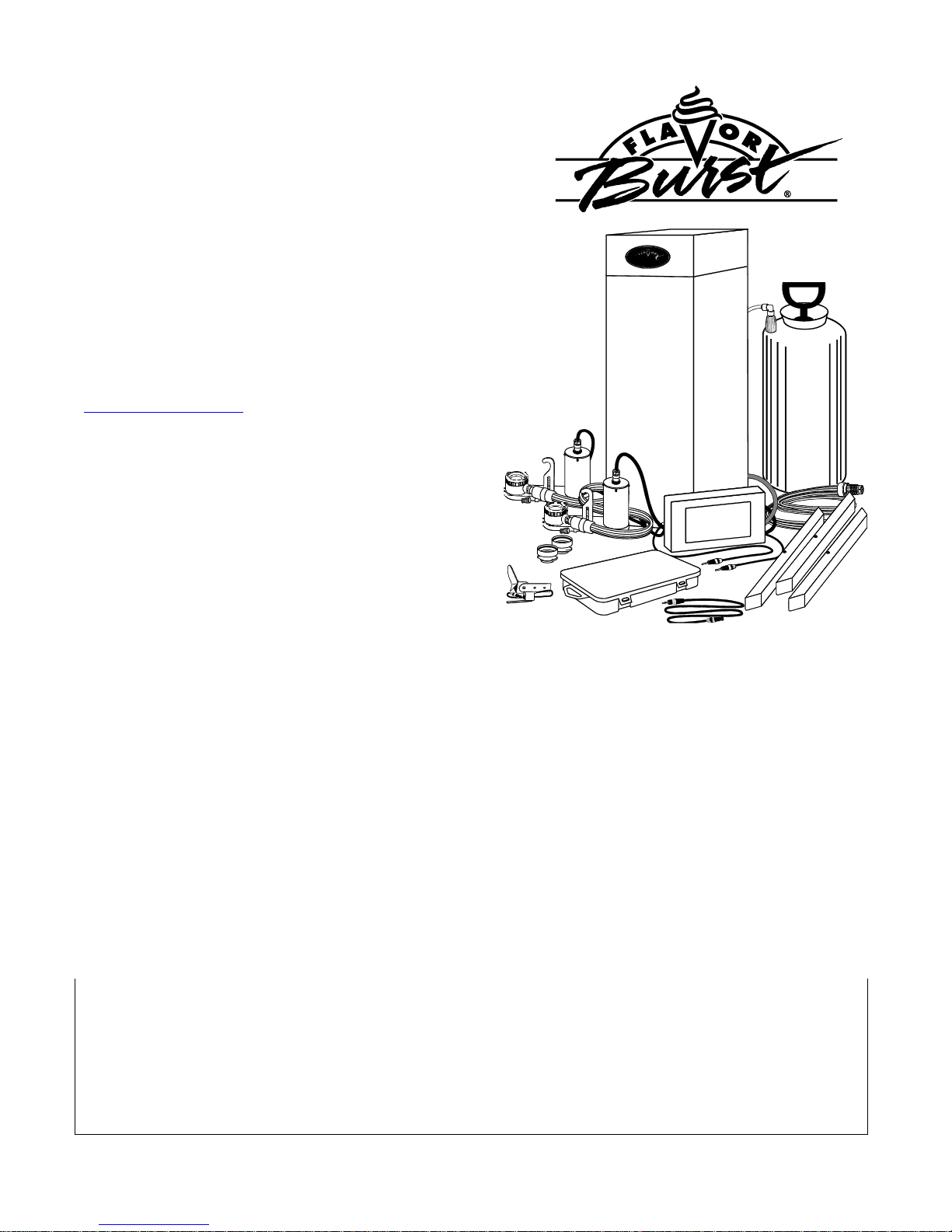
Frozen Beverage System
Model TS 44BEV
Manufactured by
Flavor Burst Company
499 Commerce Drive
Danville, IN 46122
For general information and to locate a
distributor near you, call or visit our website:
Phone: (317) 745-2952
Toll Free Number: (800) 264-3528
Fax: (317) 745-2377
www.flavorburst.com
For pricing, ordering and support, contact one
of our qualified distributors.
©2014 Flavor Burst Company Printed in January Printed in
All Rights Reserved The United States of America

1
TABLE OF CONTENTS
Safety Precautions and Procedure Notes….…………….………..……..….…………....3
Introduction……………………………...………………………………………….………….4
Parts Identification/Function……...……………………….……..…..……….……..….…..5
Daily Opening Procedures……..………………………….…….…..…….………..……...22
Sanitizing the Blending System……………………………….……………...…...…22
Assembling the Blending Assembly………………...………………………….....…23
Installing the Blending System………………………………….……………...…....23
Other items to check during opening procedures……………………………….…24
Daily Closing Procedures………………………………………….……………….………26
Removing the Blending System…………………………………...…………....…...26
Disassembling the Blending Assembly………………………………………...……27
Sanitizing the Blending System…………………………………....………….....…..27
Replacing the Syrup Flavors…………...…………………………..…….………...……...30
Scheduled Maintenance…………...……………………………….…….………...…...….34
Clean-In-Place (CIP) Procedure…………………………………....…………..…...34
CIP – Phase 1: 9-Tube Assembly Cleaning……………………………...…34
CIP – Phase 2: Syrup System Cleaning………….....……………….......…35
CIP – Phase 3: Reassembly………………………………….……….......…37
Priming the Syrup System………………………………….....…………...….......…38
Refilling the Sanitizer Tank…………………………………..........……………....…40
Cleaning the Spout Adapter………………………………….....…………...........…40
Replacing Blending Head O-Rings………………………………….....………....…41
Miscellaneous Cleaning Procedures…………………………………………......…42
Area Under the Cabinet………………………………….....……………...…42
Inside the Cabinet………………………..…….....………….……….........…43
Tube / Cable Casing Assemblies………………………….………….…..…43
Blending Assembly Suspension Bracket…………………………....………43
9-Tube Assembly Syrup Lines……………………....……………….…....…43
Winterizing the Unit ………………………………..…………...……………..…...…44

2
Equipment Setup……………………………………………………...…..……….……..….48
Installing the Spout Adapter…………………………………..…………………...…48
Installing the Touchscreen and Mounting Bracket……...………………...….....…48
Spigot Switch Options…………………………………………………………………50
Installing the ELE 510 Spigot Switch Externally……………………………………50
Installing the ELE 510 Internally on a Taylor 428 / 430 Freezer………………….52
Sanitizing the Blending System………………………………………...………....…54
Assembling the Blending Assembly…………………………………....…...…....…54
Recommended Mounting Positions for the Blending System …………...……...55
Installing the Blending System and Suspension Bracket………………….…...…56
Mounting the Tube / Cable Casing Assemblies……………………...……….....…57
Connecting the Unit Syrup Lines………………………………………….….......…59
Installing and Filling the Sanitizer Tank………………………….…………….....…62
Power Connections and Power Up……………………………………….…........…63
Installing Flavors and Priming Syrup Lines………………………...……….…...…64
Touchscreen Operations…………...…….……………………………………....……...…66
Calibrating the Touchscreen……………..….…………………………………….…66
Enabling the TS 44BEV System….……………………………………………….…67
Testing the TS 44BEV System…………..…………………....……………...…...…69
Draw Modes Options….………………………………………………………...…….70
Enabling the Standard Manual Draw Mode…………............................…71
Dispensing Product – Standard Manual Draw Mode……………….…..…72
Enabling the Timed Serving Size Draw Mode………..………………….....73
Dispensing Product – Timed Serving Size Draw Mode……………….…..74
Setting Serving Size Timing……………....………………..…................................75
Adjusting the End of Serving Delay Timing………………………………...……….77
Assigning Flavors to the Menu……………………………………………………….78
Adjusting Flavor Dispense Rate………………………...…………………….......…79
Adjusting Alternating Flavor Timing………………………………….………..….…80
Enabling the Injector Flush Feature…..……………………………………………..82
......82 Accessing the Water / Syrup Flush Mode…………………………………….……83
Accessing the Prime Syrup Pump Mode…………………………………….…...…84
Enabling Pass Code Feature.…………………………………………..…..……..…85
Accessing and Resetting the Serving Count……………………………….……….86
Accessing the Diagnostics Information...…………………....................................87
Enabling the Second Language Option……………………………………………..88
Enabling the Dispense Instruction Screen………………………………………….89
Enabling the Self Serve Mode…………………………………………………….….90
Updating and Creating Touchscreen Labels………………..…………………...…92
Uploading the Touchscreen Labels…………………………….……………….......93
Reformatting the SD Card……..…………………………………………………..…95
Directory of Cleaning Procedures……………………………...………………..…….….96
Parts Replacement Schedule………...………………….………………..….……...….…97
Recommended Maintenance Items Replacement Schedule………………....………98
Alternate Parts and Kits by Freezer Model……………………………...………..…..…98
Ordering/Service Information…………….…….…...………………………………...…..99
3
SAFETY PRECAUTIONS & PROCEDURE NOTES -- PLEASE READ!
Always follow these safety precautions when
operating the Flavor Burst® system:
DO NOT operate the system without
reading this operator’s manual. Failure to follow
this instruction may result in equipment
damage, poor system performance, health
hazards, or personal injury.
DO NOT operate the system unless it is
properly grounded. Failure to follow this
instruction may result in electrocution.
DO NOT operate the system with larger
fuses than specified on the system data label.
Failure to follow this instruction may result in
electrocution or damage to the machine.
Consult your electrician.
DO NOT put objects or fingers in the
door spout. Failure to follow this instruction may
result in contaminated product or personal
injury from blade contact.
The TS 44BEV cabinet system must be
placed on a level surface capable of supporting
at least 220 lbs of weight. Failure to comply
may result in personal injury or equipment
damage.
DO NOT install the unit in an area where
a water jet could be used, and do not use a
water jet to clean or rinse the system. Failure to
follow these instructions may result in serious
electrical shock.
NOISE LEVEL: Airborne noise emission
does not exceed 70 dB(A) when measured at a
distance of 1.0 meter from the surface of the
machine and at a height of 1.6 meters from the
floor.
NOTE: Operations Manual subject to change.
Parts and part numbers may vary from what is
shown and listed. Contact your local distributor
for most recent updates concerning the unit.
NOTE: Your hands should be cleaned and
sanitized before you perform these procedures.
NOTE: The procedures in this manual require
approved, serviceable and sanitized tools and
brushes. Contact your local distributor for
recommended supplies.
NOTE: Use an approved cleaner and sanitizer
for the procedures in this manual. Refer to
manufacturer’s instructions for proper
preparations of these cleaning agents.
NOTE: Inspect all wear items during
procedures and replace if necessary.
NOTE: Consult your local distributor if you
have any questions concerning differences.
NOTE: If installing this unit on a frozen
carbonated beverage freezer, please refer to
the TS 80FCB operations manual for
instructions on installing, maintaining and
operating the FCB side components.

4
INTRODUCTION
Congratulations on your purchase of a TS 44BEV flavoring system! As a food and beverage provider,
your customers are your greatest asset. Your primary concern must be the health and welfare of your
customers. This manual provides everyday operating guidelines and procedures. Special functions
have been incorporated into the equipment to provide simple and effective cleaning and sanitizing of
your unit. We urge you to follow these instructions carefully and maintain strict sanitary practices in your
daily operating routine.
The TS 44BEV series system is an add-on to a frozen beverage freezer designed to blend
concentrated flavorings throughout the base product as it is dispensed. Dispensing Flavor Burst
product is very simple. Select a flavor from the Touchscreen and draw the product. The Flavor Burst
system will automatically flavor the product at the spout. You can also have multiple flavors per
serving. Simply select the flavors from the Touchscreen and draw the product. The system will switch
from one flavor to the next in a smooth, continuous motion, layering the serving with different, delicious
flavors.
Flavor Burst® syrup is stored within the equipment cabinet in 1 gallon disposable bags. Proper syrup
injection rate is maintained by adjusting the flavor level on the Touchscreen.
Components of the TS 44BEV system should be cleaned daily to ensure the highest standard of
sanitation. When your equipment arrives or if it has been unused for more than 24 hours, follow the
DAILY OPENING PROCEDURES.
5
ITEM
PART NO.
DESCRIPTION
QTY.
FUNCTION
1
ELE
805BEV/BEV
TOUCHSCREEN ASSEMBLY
1
Flavor Burst unit command center.
2
ELE 434
POWER CABLE
1
Supplies the electronics board with power.
3
INJ 424VTS
VERTICAL BLENDING ASSEMBLY
2
Injects syrups into the product.
4
MIS 3196
STAINLESS TUBE / CABLE CASING
ASSEMBLY
3
Attaches the flavor lines and/or cables to the
side of the freezer.
5
SPR 5800BEV
SPARE PARTS KIT TOUCHSCREEN
BEVERAGE
1
Houses extra spare parts and wear items.
6
CAB 113
FLAVOR TRAY
8
Houses syrup bags.
7
N/A
FLAVOR BURST MX CABINET
ASSEMBLY
1
Houses syrup trays and bags.
8
SAN 740
SANITIZER TANK ASSEMBLY
1
Houses sanitizer cleaning solution.
9
SYR 944SH
SYRUP BAG CONNECTOR
ASSEMBLY - SHAKE
8
Transports syrup from the bag to the pumps.
10
SYR 935
4’ 9-TUBE ASSEMBLY EXTENSION
1
Adds length to the flavor line assembly.
11
ELE 525
36” SPIGOT SWITCH EXTENSION
WIRE
1
Adds length to the spigot switch.
12
ELE 510
SPIGOT SWITCH ASSEMBLY KIT
1
Activates the Blending Assembly.
13
ELE 810
SD CARD READER
1
Transfers updated programming and files
from the computer to the SD card.
PARTS IDENTIFICATION/FUNCTIONS
General System Overview (See Figure 1)
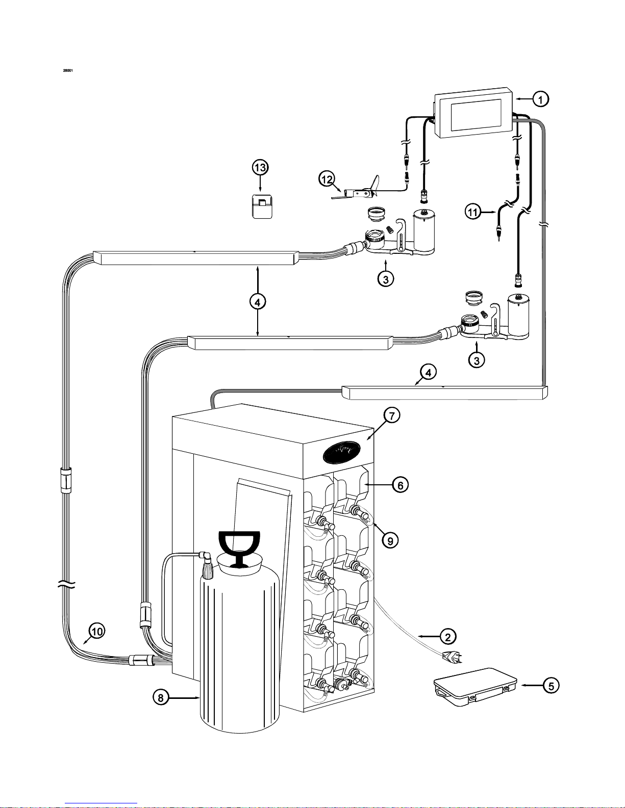
6
General System Overview
Figure 1
7
Cabinet – (See Figure 2)
ITEM
PART NO.
DESCRIPTION
QTY.
FUNCTION
1
N/A
ELECTRONICS SYSTEM
1
Houses microprocessor and electronics.
2
CAB 135R-A
RIGHT SIDE PANEL
1
Holds tray support brackets and panel
brackets.
3
CAB 145
TRAY SUPPORT BRACKET
8
Supports flavoring trays.
4
FAS 2024
8-32 X 1/4 PAN HEAD
28
Fastens panel brackets to divider panel,
secures sides.
5
FAS 2014
8-32 X 1/2" PAN HEAD
25
Attaches top panel, back cover, and
feet to cabinet.
6
SYR 944SH
SYRUP TUBE ASSEMBLY –
SHAKE
8
Transports the flavoring from the syrup bag
to the syrup pump.
7
ELE 496TS
PUMP & SANITIZER CABLE
HARNESS
1
Provides power to syrup / sanitizer pumps.
8
MIS 3066
MINI BUSHING
1
Protects flush tube.
9
MIS 3028-S
FLUSH TUBE ASSEMBLY - SHAKE
1
Connects with flavor line to flush with
sanitizer solution.
10
CAB 139
FRONT DOOR PANEL
1
Provides easy access to syrup bags and
connectors.
11
CAB 136-A
REAR PUMP COVER
1
Back panel to cover pumps.
12
FIX 1023
3/16" X 3/16" BARB TUBE CONNECT
1
Splices together flush tubes.
13
CAB 134
DIVIDER PANEL
1
Holds tray support brackets and divides trays.
14
CAB 144R
RIGHT PANEL BRACKET
3
Holds tray support rails.
15
CAB 144L
LEFT PANEL BRACKET
3
Holds tray support rails.
16
CAB 143
LATCH BRACKET
1
Provides latching tab for front panel.
17
FAS 2001
FRONT DOOR PANEL LATCH
1
Latches front door to cabinet front.
18
SYR 938
MX SERIES INTERNAL 9-TUBE
ASSEMBLY
1
Transports syrup from bags to flavor
9-Tube Assembly.
19
SAN 748
PERISTALTIC SANITIZER PUMP
1
Pumps sanitizer solution to flush tube
and sanitizer line.
20
SYR 926
PERISTALTIC SYRUP PUMP
8
Pumps syrup from flavor bags to flavor lines.
21
CAB 155L
PUMP MOUNTING STRIP
1
Support for syrup trays and spacing
between panels.
22
CAB 155R
PUMP MOUNTING STRIP
1
Supports syrup trays and spaces panels.
23
FAS 2037
TAPPED NYLON SPACER
12
Secures screw to center panel, and
support for trays.
24
FAS 2032
STANDARD NYLON SPACERS
12
Provides extra support for flavor trays.
25
FAS 2034
8-32 X 3/4" MACHINE SCREW
12
Attaches bushings to divider panel.
26
MIS 3067
OPEN/CLOSED BUSHING
1
Strain relief for internal 9-Tube Assembly.
27
FIX 1033
1/4" X 1/4" BLKHD (PUSH-TOCONNECT)
1
Connects Sanitizer Tank tube to the unit.
28
TUB 803
TUBING-PER FOOT
1
Transports sanitizer from tank to pump.
29
CAB 133
BASE PANEL
1
Attaches inner and side panel bottoms.
30
RUB 618
RUBBER BUMPER WITH WASHER
6
Provides spacing between base and table.
8
Cabinet (Continued)
ITEM
PART NO.
DESCRIPTION
QTY.
FUNCTION
31
FAS 2035
8-32 NUTS - EXT. LOCK WASHER
6
Holds rubber bumper in place.
32
MIS 3074
SHORTY PLUG #1672
6
Covers screw hole in rubber bumper.
33
FAS 2040
6-32 X 1/4" TAPPING SCREW
24
Secures tray support bracket to side panels.
34
CAB 135L-A
LEFT SIDE PANEL
1
Holds support brackets and panel brackets.
35
VAL 210
MX SERIES VALVE ASSEMBLY
1
Splits & diverts syrup from pump to activate
syrup line.
Figure 2
9
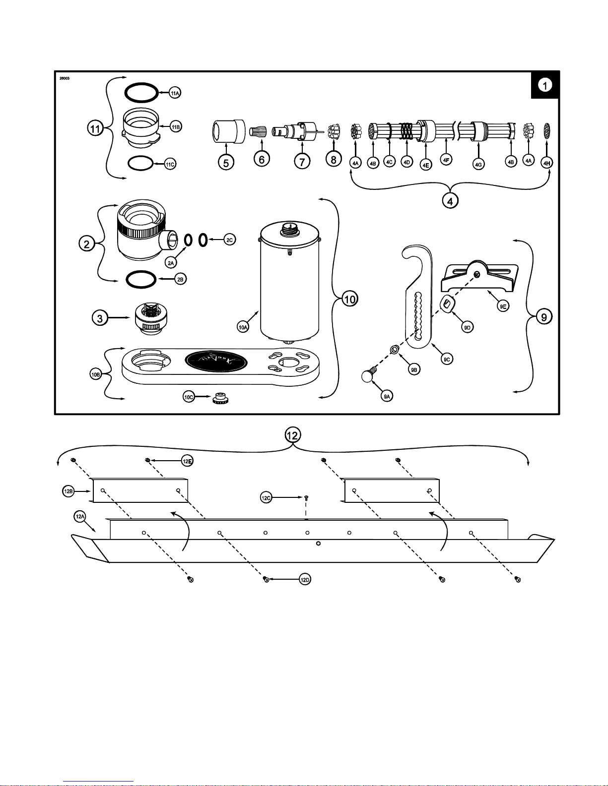
Blending Assembly and Related Parts (See Figure 3)
ITEM
PART NO.
DESCRIPTION
QTY.
FUNCTION
1
INJ 424VTS
VERTICAL BLENDING ASSEMBLY
WITH SYRUP LINES, ADAPTER, &
BRACKET
2
Transports and blends syrup into product.
2
INJ 422VS
BLENDING HEAD ASSEMBLY –
VERTICAL SHAKE
1
Connects flavor line to inject syrups into
product.
2A
RUB 652-RSS
SMALLER SYRUP PORT O-RING
1 ea.
Provides sealed cavity inside syrup port.
2B
RUB 651
BLENDING HEAD O-RING 2-020
1 ea.
Provides a sealed cavity.
2C
RUB 660
LARGER SYRUP PORT O-RING
1 ea.
Provides sealed cavity inside syrup port.
3
INJ 321S
GEAR CARTRIDGE ASSEMBLY –
VERTICAL BLENDER
1
Rotates product for even syrup distribution.
4
SYR 932
6' 9-TUBE ASSEMBLY
1
Supplies syrup to Blending Head from
pumps.
4A
FAS 2051
ROLLED FLANGE EYELET
18
ea.
Provides tension in syrup line to affix to line
coupler.
4B
ROT 510
LINE COUPLER
2 ea.
Holds flavor lines in place.
4C
RUB 610
BAG CONNECTOR O-RINGS
1 ea.
Provides extra tension between tube
connectors.
4D
ROT 515-A
9-TUBE ASSEMBLY WAVE SPRING
1 ea.
Provides tension between tube connectors.
4E
INJ 116
LINE COUPLER NUT - BLACK
1 ea.
Attaches flavor tubes to flavor manifold.
4F
SYR 901
6' 9-TUBE ASSEMBLY TUBES
9 ea.
Brings syrup from pump to Blending Head.
4G
ROT 511
LINE COUPLER NUT
1 ea.
Connects flavor lines to the internal 9-Tube
Assembly.
4H
RUB 602
9-POS TUBE CONN. GASKET
1 ea.
Provides sealed cavity.
5
INJ 117
TUBE CONNECTOR BODY –BLACK
1
Secures flavor line manifold to flavor lines.
6
MIS 3142
FLAVOR LINE DUST CAP – FB 80
1
Covers syrup manifold when not connected.
7
INJ 201A
SYRUP MANIFOLD - BLACK
1
Connects flavor line to Blending Head.
8
RUB 601
9-POS DUCKBILL CHECK VALVE
1
Provides sealed cavity and prevents syrup
leakage.
9
MIS 3146
BLENDING SUSPENSION BRACKET
ASSEMBLY
1
Secures Blending Assembly to the freezer
door.
9A
FAS 2107
INJECTOR BRACKET KNOB
1 ea.
Tightens positioning of hanging bracket.
9B
MIS 3144
NYLON SHOULDER WASHER
1 ea.
Allows free horizontal movement for
bracket.
9C
MIS 3143-A
INJECTOR BRACKET PART A
1 ea.
Attaches to freezer door bolts to hang
Injector Assembly.
9D
ROT 535
INJ. BRACKET SPRING WASHER
1 ea.
Allows space between hanging and
base brackets.
9E
MIS 3143-B
INJECTOR BRACKET PART B
1 ea.
Secures bracket assembly to Injector
Assembly.
10
Blending Assembly and Related Parts (Continued)
ITEM
PART NO.
DESCRIPTION
QTY.
FUNCTION
10
INJ 323TS
BLENDING ASSEMBLY - NO HEAD
1
Powers Blending system.
10A
INJ 330TS
BLENDING MOTOR ASSEMBLY
1 ea.
Supplies power to Motor which turns gears.
10B
INJ 331
BLENDING GEARBOX ASSEMBLY
1 ea.
Gears turn Gear Cartridge for even syrup
distribution.
10C
FAS 2023
ACCESSORY MOUNTING BRACKET
KNOB
1 ea.
Secures base Mounting Bracket to Gear Box.
11
ADPT 104R-A
CROWN ADAPTER WITH
O-RINGS
1
Attaches Blending Assembly to freezer door.
11A
RUB 627
TAYLOR ADAPTER O-RING 8750
1 ea.
Creates tension to secure adapter to freezer
door.
11B
ADPT 104R
CROWN ADAPTER WITOUT
O-RINGS
1 ea.
Attaches Blending Assembly to freezer door.
11C
RUB 632
BLENDING ADAPTER O-RING
1 ea.
Creates tension to secure adapter to
Blending Head.
12
MIS 3196
STAINLESS 9-TUBE CASING
ASSEMBLY
3
Protects and holds the cables and 9-Tube
Assembly in place on the freezer side panel.
12A
MIS 3190
STAINLESS 9-TUBE CASING HINGED
CHANNEL
1 ea.
Covers and protects the cables and tubes of
the Casing Assembly.
12B
MIS 3051
CH-6 CHANNEL MAGNET ASSEMBLY
2 ea.
Holds the Casing Channel to the freezer
panel.
12C
FAS 2040
6-32 x 1/4 PAN HEAD SCREW
1 ea.
Secures the Casing cover to the mounting
brackets.
12D
FAS 2024
8-32 x 1/4 PAN HEAD SCREW
4 ea.
Secures the magnet assembly to the
mounting brackets.
12E
FAS 2035
8-32 NUTS-EXT. LOCK WASHER
4 ea.
Secures the magnet assembly to the
mounting brackets.

11
PAGE INTENTIONALLY LEFT BLANK
12
Blending Assembly and Related Parts
Figure 3
13
Syrup Pump and Related Parts (See Figure 4)
ITEM
PART NO.
DESCRIPTION
QTY.
FUNCTION
1
N/A
SHAKE SYRUP PUMP
8
Pumps syrup from flavor bags to flavor
lines.
1A
SYR 926
PERISTALTIC SYRUP PUMP
1
EACH
Pumps syrup from flavor bags into flavor
lines.
1B
TUB 809
1/4" SYRUP SHAKE PUMP
REPLACEMENT TUBE
1
EACH
Transports syrup through pump.
1C
FIX 1045
1/4" TUBE TO 1/4" HOSE STEM
2
EACH
Creates tension for tighter fit, connects
pump to fitment.
1D
FIX 1035
1/4 TO 3/16 OD REDUCING UNION
1
EACH
Connects syrup pump to flavor line out.
1E
FIX 1036
1/4" TO 1/4" OD UNION ELBOW
1
EACH
Connects bag connector assembly to flavor
line/pump.
2
SYR 944SH
SYRUP TUBE ASSEMBLY –
SHAKE BAG COUPLER
8
Transports the flavoring from the syrup bag
to the syrup pump.
2A
SYR 928
#27-1102-99 .265" BAG COUPLER
1
EACH
Fastens bag fitment to bag connector.
2B
TUB 811
TUBE-SILICONE .188X.375 PE
FB80
1
EACH
Provides sealed cavity inside bag fitment.
2C
FIX 1048
FITTING ¼ X ¼ BARB FB80
1
EACH
Connects bag coupler assembly to flavor
line/pump.
2D
SYR 902
FLAVOR-IN TUBE
1
EACH
Carries syrup from syrup bag to pump.
3
FAS 2051
ROLLED FLANGE EYELET
18
Creates tension for tighter fit, 9 per Tube
Assembly.
4
MIS 3023
DUST CAP
2
Cover to protect end of flavor lines.
5
CAB 113
FLAVORING TRAY
8
Houses syrup bags.
6
ELE 496TS
PUMP & SANITIZER CABLE
HARNESS
1
Supplies power from microprocessor to
pump.
7
SYR 900
4' 9-TUBE ASSEMBLY TUBES
11
Brings syrup from pump to Blending Head.
8
ROT 511
LINE COUPLER NUT
2
Connects flavor lines to the internal 9-Tube
Assembly.
9
ROT 512
TUBE CONNECTOR BODY
2
Connects internal 9-Tube Assembly to
flavor lines.
10
ROT 510
LINE COUPLER
2
Holds flavor lines in place.
14
Syrup Pump and Related Parts
Figure 4
15
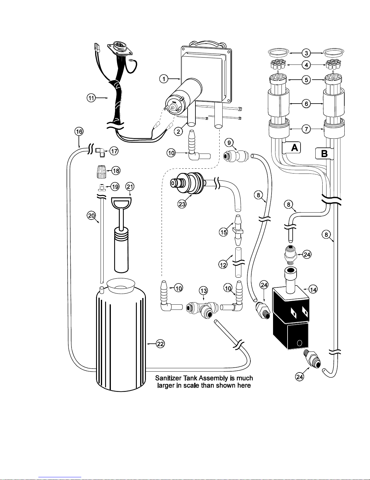
Sanitizer Pump and Related Parts (See Figure 5)
ITEM
PART NO.
DESCRIPTION
QTY.
FUNCTION
1
SAN 748
SANITIZER PUMP ASSEMBLY
1
Supplies sanitizer to flush tube.
2
TUB 807
SANITIZER TUBE REPLACEMENT
1
Transports sanitizer through pump.
3
MIS 3023
DUST CAP
2
Cover to protect end of flavor lines.
4
FAS 2051
ROLLED FLANGE EYELET
18
Creates tension for tighter fit 1 per
pump, 9 per tube assembly.
5
ROT 510
LINE COUPLER
2
Holds flavor lines in place.
6
ROT 512
TUBE CONNECTOR BODY
2
Connects internal 9-Tube Assembly to
flavor lines.
7
ROT 511
LINE COUPLER NUT
2
Connects flavor lines to the internal
9-Tube Assembly.
8
SYR 900
4' 9-TUBE ASSEMBLY TUBES
11
Transports syrup and sanitizer from
pumps to Injector Assembly.
9
FIX 1035
1/4 TO 3/16 OD REDUCING UNION
1
Connects elbow to sanitizer line.
10
FIX 1042
TUBE-TO-TUBE ELBOW
3
Connects pump tube to reducing union.
11
ELE 496TS
PUMP & SANITIZER CABLE
HARNESS
1
Provides power to the sanitizer pump.
12
SYR 931
CLEAR TUBING
1
Transports sanitizer to Pump Flush Adapter.
13
FIX 1053
SANITIZER PUMP T CONNECTOR
1
Connects sanitizer line to flush adapter
and pump lines.
14
VAL 209
MX SERIES DIVERTER VALVE
1
Splits and diverts syrup from pump to active
syrup line.
15
FIX 1023
3/16" X 3/16" BARB TUBE CONNECT
1
Splices together flush tubes.
16
TUB 803
.17 x 1/4 LDPE TUBING-PER FOOT
1
Transports sanitizer solution from tank
to sanitizer pump.
17
FIX 1036
1/4" TO 1/4" OD UNION ELBOW
1
Connects sanitizer tube to supply tube.
18
SAN 715
SUPPLY TUBE CAP
1
Fastens grommet securely to tank.
19
RUB 615
FEEDER TUBE RUBBER GROMMET
1
Holds sanitizer tube in place and seals
tank hole.
20
SYR 902
SANITIZER SUPPLY TUBING
1
Supplies sanitizer from Sanitizer Tank.
21
SAN 734
HAND PUMP ASSEMBLYFLUTEDTANK
1
Seals Sanitizer Tank and adds pressure
when needed.
22
SAN 701
SANITIZER TANK
1
Holds sanitizer solution.
23
MIS 3028-S
CONNECTOR FLUSH ASSEMBLY SHAKE
1
Connects to flavor line to flush with
Sanitizer solution.
24
FIX 1032
3/16” X 1/8” NPTF (PUSH-TOCONNECT)
3
Connects flavor lines to diverter valve.
16
Sanitizer Pump and Related Parts
Figure 5
17
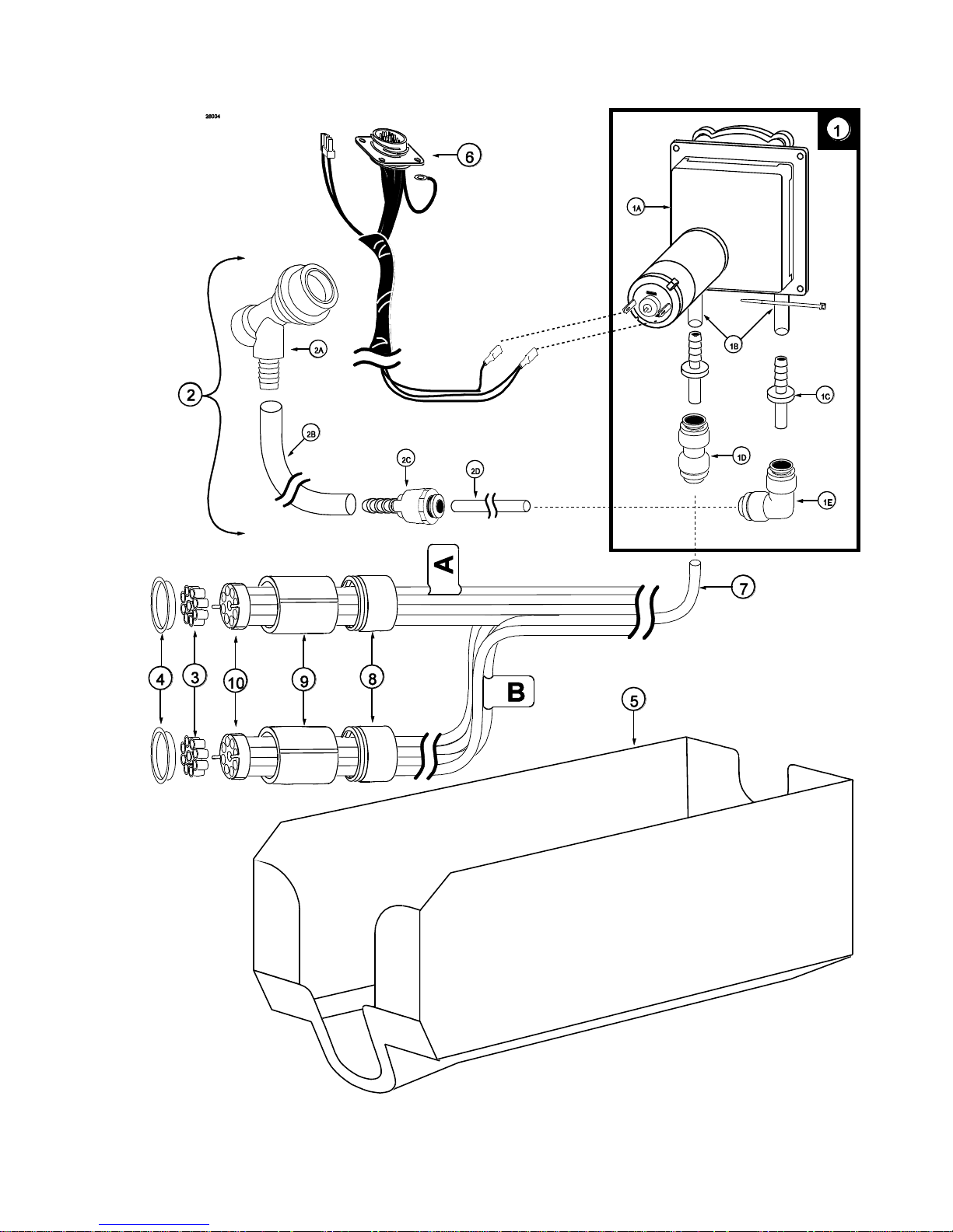
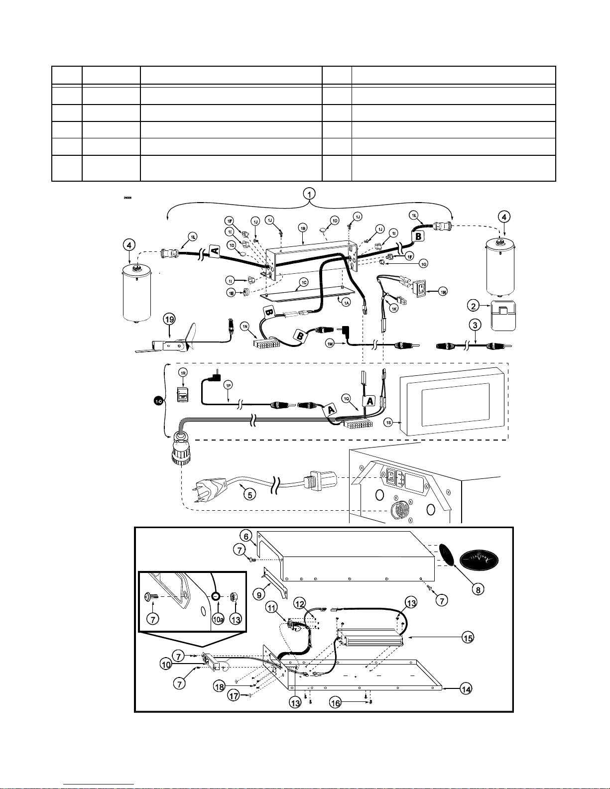
Electronic Parts and Connections (See Figure 6)
ITEM
PART NO.
DESCRIPTION
QTY.
FUNCTION
1
ELE
805BEV/BEV
TOUCHSCREEN ASSEMBLY
1
Flavor Burst unit command center.
1A
MIS 3076
ADHESIVE PAD
1 ea.
Secures the mounting bracket to the freezer.
1B
MIS 3200
TOUCHSCREEN CABLE HOUSING MOUNT
1 ea.
Houses Touchscreen electronic connections.
1C
CW 214
TOUCHSCREEN MOUNTING PLATE
1 ea.
Mounts the Touchscreen to the freezer.
1D
FAS 2023
ACCESSORY MOUNTING BRACKET KNOB
2 ea.
Secures the housing mount to the Plate.
1E
MIS 3198
TUBE CLAMP 5/16”
1 ea.
Secures the Touchscreen power cable.
1F
MIS 3034
STRAIN RELIEF BUSHING
2 ea.
Protects the switch and motor cables.
1G
MIS 3192
LOCKING HOLE PLUG
1 ea.
Closes up extra openings.
1H
CW 152
ON/OFF TOUCHSCREEN SWITCH
1 ea.
Powers the Touchscreen on and off.
1
MIS 3191
OPEN-CLOSE BUSHING
3 ea.
Protects the Touchscreen power cable.
1J
FAS 2024
8-32 X 1/4 PAN HEAD SCREW
4 ea.
Secures the housing to the Touchscreen.
1K
ELE 801
SWITCH WIRING
1 ea.
Connects ON/OFF switch to Touchscreen.
1L
ELE 506TS
TOUCHSCREEN ROTOR CABLE ASSEMBLY
2 ea.
Connects the drive motor to Touchscreen.
1M
ELE 525M
MALE TO MALE 48” SWITCH EXTENSION
1 ea.
Connects Touchscreen to the freezer switch.
1N
ELE 803
TS 44 ROTOR AND SWITCH CABLE
CONNECTOR
1 ea.
Activates “B” rotor and switch connections.
1
Activates Blending Assembly.
1-O
ELE 805
TOUCHSCREEN SUB-ASSEMBLY
1 ea.
Control center for the Flavor Burst system.
1P
ELE 525M
MALE TO MALE 48” SWITCH EXTENSION
1 ea.
Connects Touchscreen to the freezer switch.
1Q
ELE 215TS
TOUCHSCREEN CONTROLLER CABLE
1 ea.
Activates “A” rotor and switch connections.
1R
ELE 807
SD CARD
1 ea.
Transfers updated files and programming
from the computer to the Touchscreen.
1S
N/A
TOUCHSCREEN ASSEMBLY
1 ea.
Command center for Flavor Burst systems.
2
ELE 810
SD CARD READER
1
Transfers updated programming and files
from the computer to the SD card.
3
ELE 525
36” SPIGOT SWITCH EXTENSION WIRE
1
Adds length to the spigot switch.
4
INJ 330TS
INJECTOR MOTOR ASSEMBLY
2
Supplies power to Motor which turns gears.
5
ELE 434
POWER CABLE
1
Supplies the electronics board with power.
6
CAB 137-A
ELECTRONICS COVER
1
Protects and covers electronics microprocessor.
7
FAS 2014
8-32 X 1/2" PAN HEAD
16
Secures various parts within the top of unit.
8
MIS 3150
FLAVOR BURST LOGO DECALS
1
Displays Flavor Burst trademark logo.
9
CAB 156
CONNECTOR SHIELD
1
Protects power cables from liquids.
10
ELE 485
120V POWER ENTRANCE MODULE
1
Power source inlet.
10A
N/A
GROUNDING WIRE
1 ea.
Grounds electricity.
11
ELE 496TS
PUMP & SANITIZER CABLE HARNESS
1
Provides power to syrup & sanitizer pumps.
11A
N/A
GROUNDING WIRE
1 ea.
Grounds electricity.
12
FAS 2042
4/40 LOCK NUTS
4
Secures screws to mount pump cable face.
13
FAS 2035
8-32 NUTS - EXT. LOCK WASHER
5
Secures ground wire to screw and
Panel and the Electronics Box to the panel.
14
CAB 138TS
ELECTRONICS BASE PANEL
1
Secures microprocessor.
18
Electronic Parts and Connections (Continued)
ITEM
PART NO.
DESCRIPTION
QTY.
FUNCTION
15
ELE 806
POWER SUPPLY
1
Main power supply.
16
FAS 2024
8-32 X 1/4 PAN HEAD SCREW
4
Secures power supply to the base panel.
17
MIS 3166
CLOSURE PLUG
2
Closes up extra openings.
18
FAS 2008
4-40 X 3/8" PAN HEAD SCREWS
4
Attaches pump cable face to panel.
19
ELE 510
SPIGOT SWITCH
1
Alternate switch to activate the Blending
Assembly.
Figure 6

19
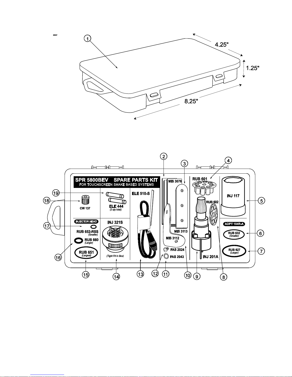
Spare Parts Kit (See Figure 7)
ITEM
PART NO.
DESCRIPTION
QTY.
FUNCTION
1
SPR
5800BEV
SPARE PARTS KIT – TOUCHSCREEN
BEVERAGE
1
Houses extra spare parts and wear items.
2
MIS 3076
ADHESIVE PAD
3
Provided to attach switch to freezer or mount
brackets.
3
MIS 3113
PANEL SWITCH MOUNTING ARM
1
Bracket to mount spigot switch.
4
RUB 601
9-POS DUCKBILL CHECK VALVE
1
Provides sealed cavity and prevents syrup
leakage.
5
INJ 117
TUBE CONNECTOR BODY -BLACK
1
Secures flavor line manifold to flavor lines.
6
RUB 632
LOWER ADAPTER O-RING
1
Creates tension to secure adapter to
blending head.
7
RUB 627
UPPER ADAPTER O-RING - FOR
ADPT 104R-A
1
Creates tension to secure adapter to freezer
door.
8
RUB 602
9-POS TUBE CONN. GASKET
1
Provides sealed cavity.
9
INJ 201A
SYRUP MANIFOLD
1
Connects flavor line to blending head.
10
MIS 3112
PANEL SWITCH MOUNTING BRKT
1
Bracket to mount spigot switch.
11
FAS 2043
INTERNAL TOOTH LOCK WASHER
1
Locks brackets into place with screw.
12
FAS 2024
8-32 X 1/4 PAN HEAD
1
Fastens switch brackets together.
13
ELE 510-S
SPIGOT SWITCH
1
Activates Blending Assembly.
14
INJ 321S
GEAR CARTRIDGE ASSEMBLY –
VERTICAL BLENDER
1
Provides sealed cavity inside syrup port.
15
RUB 651
INJECTOR HEAD O-RING 2-020
1
Provides a sealed cavity.
16
RUB 660
LARGER SYRUP PORT O-RING
1
Provides sealed cavity inside syrup port.
17
RUB 652-RSS
SMALLER SYRUP PORT O-RING
1
Provides sealed cavity inside syrup port.
18
CW 137
DRIVE MOTOR GEAR
1
Turns the gear box gears, powered by the
drive motor.
19
ELE 444
1 AMP, 1 1/4" SLOW BLOW FUSE
2
System overload protection.
20
Spare Parts Kit
Figure 7

21
PAGE INTENTIONALLY LEFT BLANK
22
DAILY OPENING PROCEDURES
NOTE: PERFORM THE FOLLOWING
PROCEDURES FOR EACH BLENDING
ASSEMBLY.
NOTE: ENSURE THAT THE BLENDING
SYSTEM HAS BEEN DISASSEMBLED AND
CLEANED ACCORDING TO THE DAILY
CLOSING PROCEDURES. THIS IS
TYPICALLY PERFORMED AT THE CLOSE OF
THE PREVIOUS BUSINESS DAY.
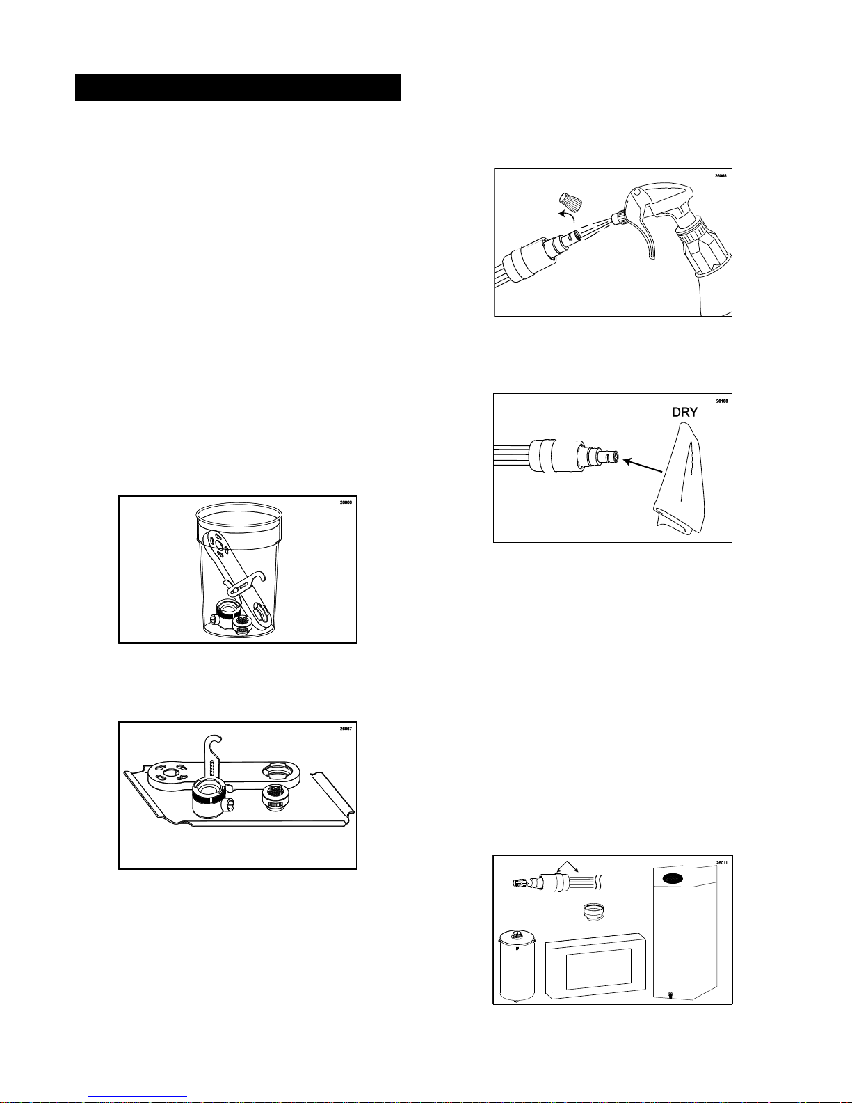
Sanitizing the Blending System
1. Prepare an approved sanitizer solution
according to manufacturer’s instructions.
2. Place the Gear Box, Suspension Bracket,
Gear Cartridge, and Blending Head in
approved sanitizer solution and soak for 1
minute.
4. Remove the Manifold cap and set it on a
sanitary tray. Spray the Syrup Line
Manifold opening with approved sanitizer
solution and allow it to sanitize for at least 1
minute.
5. Dry the end of the manifold with a clean
single service towel.
3. Remove each part from the sanitizer
solution. Place the items on a sanitary tray
to air dry.
6. The following do not need to be sanitized on
a daily basis as part of the daily opening
procedures. However, inspect these areas
and if necessary, clean according to
instructions in the SCHEDULED
MAINTENANCE section:
9-Tube Assembly Coupler
9-Tube Assembly Tubes
Touchscreen surface
Spout Adapter (clean according
to instructions when freezer
door has been removed)
Drive Motor
Exposed surfaces of Cabinet
23
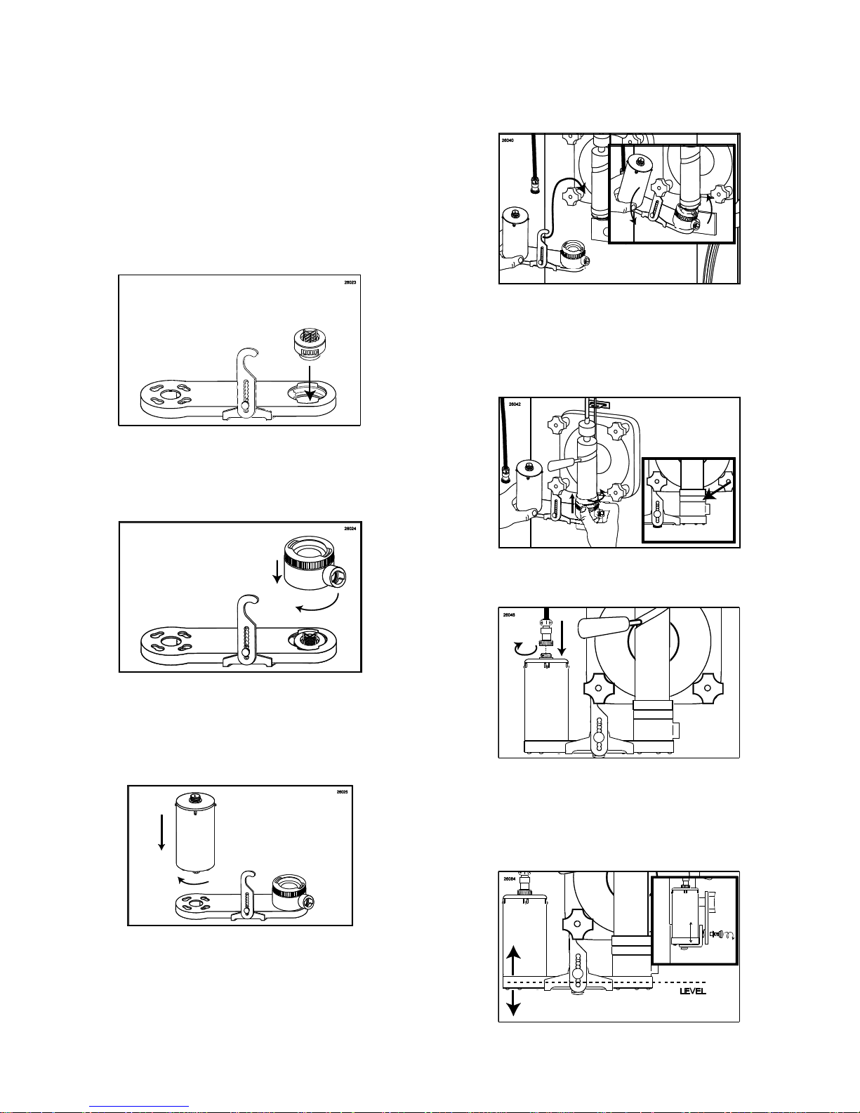
Assembling the Blending Assembly
The two Blending Head o-rings and the Gear
Cartridge are wear items and will need to be
replaced periodically. Check for wear
occasionally and always keep spares of these
items on hand in the Spare Parts Kit.
1. Place the Gear Cartridge into the Drive
Assembly Gear Box so that the gear teeth
line up with the gear inside the Drive
Assembly Gear Box.
2. Install the Blending Head onto the Drive
Assembly Gear Box and rotate off-center to
secure.
Installing the Blending System
1. Hang the Suspension Bracket with the
Blending Assembly on the door post.
2. Install the Blending Head fully over the
Spout Adapter so that the locking collar
covers the tabs on the Adapter. Rotate the
locking collar to secure.
3. Insert the Drive Motor into the Drive
Assembly Gear Box so that all four locking
screws are seated properly and rotate the
motor clockwise to secure.
3. Connect the Drive Motor cable to the Motor.
4. Ensure that the Blending Assembly is level
horizontally and make any adjustments to
the Suspension Bracket as needed using
the adjustment hand knob.
24
5. Insert the Syrup Line Manifold end fully into
the Blending Head syrup line opening.
Rotate it until motion stops to secure.
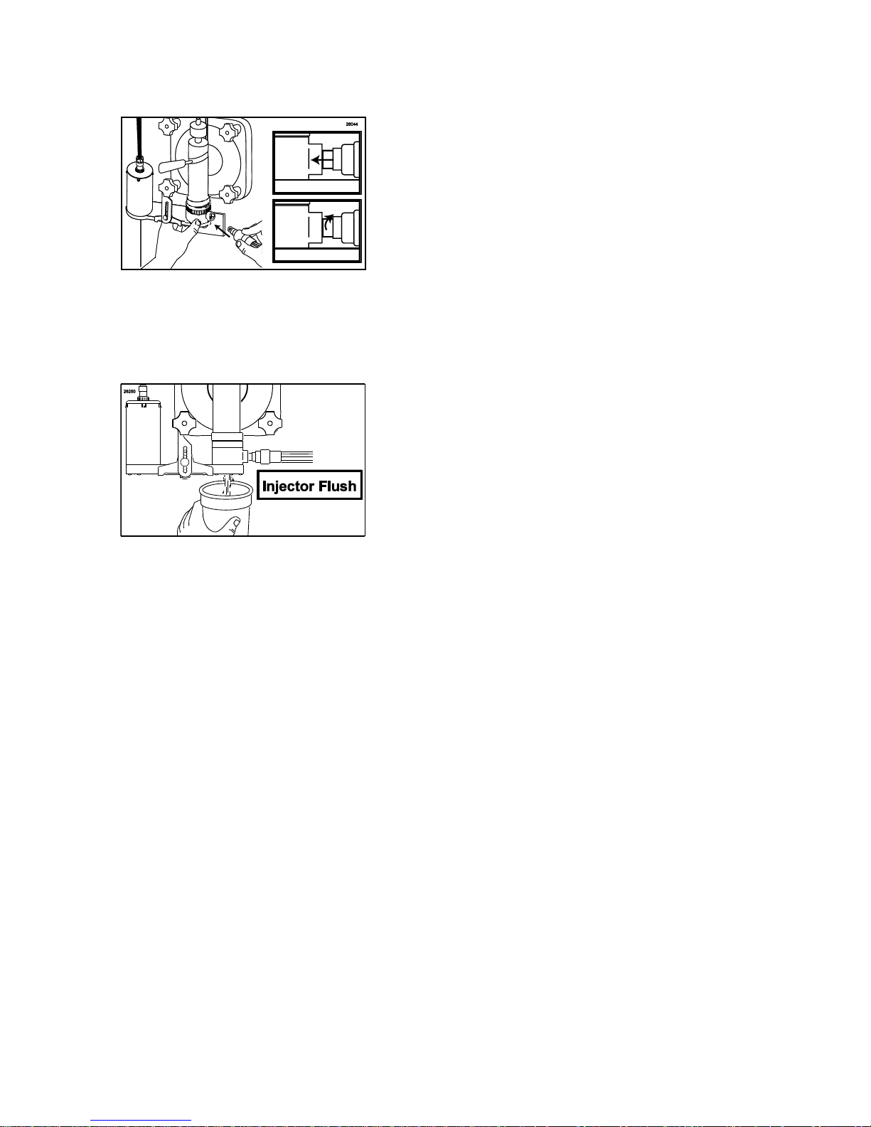
6. With a container under the dispensing
spout, press the INJECTOR FLUSH key on
the Touchscreen to purge any remaining
product from the Blending Head.
Other items to check during opening
procedures
These steps do not necessarily need to be
performed as part of the daily opening
procedures. The following is a list of areas to
check on the Flavor Burst® system during
opening procedures. These areas should be
checked and adjusted if necessary.
1. Ensure that the Sanitizer Tank has plenty of
approved sanitizer solution and refill
according to instructions if necessary.
2. Ensure that desired flavors are installed and
that none of the flavor bags are empty.
Replace flavors according to instructions if
necessary.
3. Ensure that the flavor level and the multiflavored timing are set to a desired level.
Make adjustments according to instructions
according to the operator’s preference.

25
PAGE INTENTIONALLY LEFT BLANK
26
DAILY CLOSING PROCEDURES
NOTE: PERFORM THE FOLLOWING
PROCEDURES FOR EACH BLENDING
ASSEMBLY.
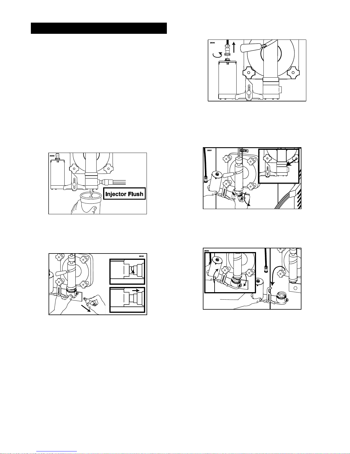
Removing the Blending System
Follow these instructions to remove the
Blending System from the freezer during
closing.
1. With a container under the dispensing
spout, press the INJECTOR FLUSH key on
the Touchscreen to purge any remaining
product from the Blending Head.
3. Disconnect the Drive Motor cable from the
Drive Motor.
4. Rotate the Blending Head locking collar until
it unlocks from the Spout Adapter and
remove the Blending Head from the
Adapter.
2. Rotate the 9-Tube Assembly coupler until it
unlocks and is able to slide out of the
Blending Head syrup line opening.
5. Lift the Suspension Bracket with the
Blending Assembly from the freezer door
knob.
27
Disassembling the Blending Assembly
1. Rotate the Drive Motor to unlock and
remove the Drive Motor from the Drive
Assembly Gear Box.
2. Rotate the Blending Head to unlock it from
the Gear Box.
Sanitizing the Blending System
1. Mix approved detergent with warm water
according to manufacturer’s instructions.
Also prepare approved sanitizer solution
according to manufacturer’s instructions.
2. Place the Drive Assembly Gear Box in
warm water and soak for at least 5 minutes.
Proceed with Steps 3 and 4 in the
meantime.
3. Brush and clean all exposed surfaces of the
Gear Cartridge with detergent water, then
rinse thoroughly.
3. Remove the Gear Cartridge from the Gear
Box.
4. Brush and clean all exposed surfaces of the
Blending Head with detergent water, then
rinse thoroughly. Use a small brush to
ensure that the syrup orifices are clear of
any residual syrup.
28
5. When the Drive Assembly Gear Box has
soaked for at least 5 minutes, brush and
clean all exposed surfaces and openings
with detergent water and rinse thoroughly.
The Suspension Bracket may be
disassembled for a more thorough cleaning
if necessary.
NOTE: UNDER NORMAL OPERATING
CONDITIONS, IT IS NOT ADVISORY TO
BRUSH OTHER AREAS INSIDE THE DRIVE
ASSEMBLY GEAR BOX. DOING SO MAY
CAUSE DAMAGE.
NOTE: DO NOT OPEN OR DISASSEMBLE
THE DRIVE ASSEMBLY GEAR BOX.
6. Place the Gear Box, Suspension Bracket,
Gear Cartridge, and Blending Head in
approved sanitizer solution and soak for at
least 1 minute.
8. Spray the Syrup Line Manifold opening with
approved sanitizer solution. Allow it to
sanitize for at least 1 minute.
9. Dry the end of the manifold with a clean
single service towel.
10. Install the cap on the manifold.
7. Remove each part from the sanitizer
solution. Place the items on a sanitary tray
to air dry.
11. Clean, rinse and dry the surfaces of the
Drive Motor, the Touchscreen, and exposed
surfaces of the cabinet using detergent
water, clean water, and single service
towels.
29
12. The following do not need to be sanitized on
a daily basis. However, inspect these areas
and if necessary, clean according to
instructions in the SCHEDULED
MAINTENANCE section:
9-Tube Assembly Coupler
9-Tube Assembly Tubes
Spout Adapter (clean according to
instructions when freezer door has been
removed)
 Loading...