


Flavor Burst CTP 80BLD Installation Manual
Flavor Burst ®
Soft Serve Blend System
Model CTP 80BLD
Equipment, Maintenance and
Operations Manual for
Manufactured by
Flavor Burst Company
499 Commerce Drive
Danville, IN 46122
For general information and to locate a
distributor near you, call or visit our website:
Phone: (317) 745-2952
Toll Free Number: (800) 264-3528
Fax: (317) 745-2377
www.flavorburst.com
For pricing, ordering and support, contact one
of our qualified distributors.
Warranty
An installation and warranty form is provided with every CTP 80BLD system, located inside the
CTP 80BLD unit with this manual. It is important that the operator carefully review the warranty and
installation documents accompanying the unit before using this system. Any questions or concerns
regarding the warranty should be clarified upon delivery or installation. For more information, contact
your local authorized Flavor Burst
©2017 Flavor Burst Company Printed in November Printed in
All Rights Reserved The United States of America
®
distributor.

TABLE OF CONTENTS
FCC ID……………………………...………………………………………….………………...3
Introduction……………………………...………………………………………….………….4
Safety Precautions……………………………..…………….………..……..….…………....4
Environmental Notices………………...………………………………………….………….5
Parts Identification/Function……...……………………….……..…..……….……..….…..7
Daily Opening Procedures……..………………………….…….…..…….………..……...26
Sanitizing the Blending System………………………….….………………..…...…26
Assembling the Blending Assembly………………...…..………………………...…27
Installing the Blending System………………………………….……….……...…...28
Other items to check during opening procedures……………………………….…29
Daily Closing Procedures………………………………………….……………….………30
Removing the Blending System………………………………....……………...…...30
Disassembling the Blending Assembly………………..……………………….……31
Sanitizing the Blending System…………………………………..……………...…..31
Replacing the Syrup Flavors…………...…………………………..…….………...……...34
Scheduled Maintenance…………...……………………………….…….………...…...….38
Clean-In-Place (CIP) Procedure…………………………………....…………..…...38
CIP – Phase 1: Prep………………………...……………………………...…38
CIP – Phase 2: Flush……………………………….....……………….......…40
CIP – Phase 3: Clean………………………………………….……….......…41
CIP – Phase 4: Reassemble………………………………….……….......…42
Priming the Syrup System………………………………….....…………...….......…43
Refilling the Sanitizer Tank…………………………………..........……………....…44
Replacing Blending Head O-Rings………………………………….....….……...…45
Replacing the Wireless Spigot Switch Battery…………………………………......46
Miscellaneous Cleaning Procedures…………………………………………......…47
Area Under the Cabinet………………………………….....……………...…47
Inside the Cabinet………………………………….....………………….....…47
Tube / Cable Casing Assemblies………………………….………….…..…47
Blending Assembly Suspension Bracket………………………….....…..…48
9-Tube Assembly Syrup Lines……………………....……………….…....…48
Touch Panel and Mounting Bracket……………....……………….……...…48
Winterizing the Unit ………………………………..…………...……………..…...…49
1

TABLE OF CONTENTS (continued)
Equipment Setup……………………………………………………...…..……….……..….52
Installing the Touch Panel and Mounting Bracket………………………...….....…52
Spigot Switch Options……………………………………….………...…………...…54
Installing the Wireless Spigot Switch…………...………………………...…54
Installing the Spigot Switch Extension…………….……………………...…55
Installing the Draw Handle Switch…………………….……...…………...…55
Sanitizing the Blending System………………………………….…...…………...…55
Assembling the Blending Assembly…………………………….…....……...…...…56
Installing the Spout Adapter…………………………………..…………………...…57
Installing the Blending System and Suspension Bracket………….…………...…57
Mounting the Tube / Cable Casing Assemblies……………………...……….....…59
Installing and Filling the Sanitizer Tank………………………….…………….....…60
Connecting the Unit Syrup Line……………………………………………….......…61
Power Connections and Power Up……………………………………….…........…62
Installing Flavors and Priming Syrup Lines………………………...……….…...…63
Color Touch Panel Overview.…….………………..…………………………....……...…66
Quick Reference Guide for Color Touch Panel Setup..…..……...…….………….66
Testing the CTP 80BLD System………..…….………………………..…...….....…67
Directory of Cleaning Procedures……………………………...………………..…….….70
Parts Replacement Schedule………...………………….………………..….……………71
Recommended Maintenance Items Replacement Schedule………………....…....…72
Alternate Parts and Kits by Freezer Model……………………………...……...…....….72
Ordering/Service Information…………….…….…...…………………..……….........…..73
2

FCC ID 必须要加的警告语:
This device complies with Part 15 of the FCC Rules. Operation is subject to the following two
conditions: (1) this device may not cause harmful interference, and (2) this device must accept any
interference received, including interference that may cause undesired operation.
Changes or modifications not expressly approved by the party responsible for compliance could void
the user's authority to operate the equipment.
NOTE: This equipment has been tested and found to comply with the limits for a Class B digital device,
pursuant to Part 15 of the FCC Rules. These limits are designed to provide reasonable protection
against harmful interference in a residential installation. This equipment generates, uses and can
radiate radio frequency energy and, if not installed and used in accordance with the instructions, may
cause harmful interference to radio communications. However, there is no guarantee that interference
will not occur in a particular installation. If this equipment does cause harmful interference to radio or
television reception, which can be determined by turning the equipment off and on, the user is
encouraged to try to correct the interference by one or more of the following measures:
-- Reorient or relocate the receiving antenna.
-- Increase the separation between the equipment and receiver.
-- Connect the equipment into an outlet on a circuit different from that to which the receiver is
connected.
-- Consult the dealer or an experienced radio/TV technician for help.
FCC RF Radiation Exposure and SAR Statements SAR Statement.
The Flavor 10* has been tested for body-worn Specific Absorption Rate (SAR) compliance. The FCC
has established detailed SAR requirements and has established that these requirements. RF Exposure
Information. The radio module has been evaluated under FCC Bulletin OET 65C (01-01) and found to
be compliant to the requirements as set forth in CFR 47 Sections, 2.1093, and 15.247 (b) (4)
addressing RF Exposure from radio frequency devices. This model meets the applicable government
requirements for exposure to radio frequency waves. The highest SAR level measured for this device
was 0.293W/kg.
*The Flavor 10 is also referred to as the Touch Panel throughout this manual.
3

INTRODUCTION
Congratulations on your purchase of a CTP
80BLD series flavoring system! As a food and
beverage provider, your customers are your
greatest asset. Your primary concern must be
the health and welfare of your customers. This
manual provides everyday operating guidelines
and procedures. Special functions have been
incorporated into the equipment to provide
simple and effective cleaning and sanitizing of
your unit. We urge you to follow these
instructions carefully and maintain strict sanitary
practices in your daily operating routine.
The CTP 80BLD series system is an add-on to
a soft serve freezer designed to blend
concentrated flavorings throughout soft serve
product as it is dispensed. Dispensing Flavor
Burst product is very simple. Select a flavor
from the Touch Panel and draw the product.
The Flavor Burst system will automatically
flavor the product at the spout. You can also
have multiple flavors per serving. Simply select
the flavors from the Touch Panel and draw the
product. The system will switch from one flavor
to the next in a smooth, continuous motion,
layering the serving with different, delicious
flavors.
Flavor Burst
®
syrup is stored within the
equipment cabinet in 1 gallon disposable bags.
Proper syrup injection rate is maintained by
adjusting the flavor level on the system Touch
Panel.
Components of the CTP 80BLD system should
be cleaned daily to ensure the highest standard
of sanitation. When your equipment is
delivered or if it has been unused for more than
24 hours, follow the DAILY OPENING
PROCEDURES.
NOTE: PARTS AND PART NUMBERS MAY
VARY FROM WHAT IS SHOWN AND LISTED.
CONSULT YOUR LOCAL DISTRIBUTOR IF
YOU HAVE ANY QUESTIONS CONCERNING
DIFFERENCES.
SAFETY PRECAUTIONS
Always follow these safety precautions when
operating the Flavor Burst
®
system:
DO NOT operate the system without
reading this operator’s manual. Failure to follow
this instruction may result in equipment
damage, poor system performance, health
hazards, or personal injury.
DO NOT operate the system unless it is
properly grounded. Failure to follow this
instruction may result in electrocution.
DO NOT operate the system with larger
fuses than specified on the system data label.
Failure to follow this instruction may result in
electrocution or damage to the machine.
Consult your electrician.
DO NOT put objects or fingers in the
door spout. Failure to follow this instruction may
result in contaminated product or personal
injury from blade contact.
The CTP 80BLD cabinet system must be
placed on a level surface capable of supporting
at least 220 lbs of weight. Failure to comply
may result in personal injury or equipment
damage.
DO NOT place more than 25 lbs of
weight on top of the Flavor Burst cabinet.
Failure to comply may result in personal injury
or equipment damage.
DO NOT install the unit in an area where
a water jet could be used, and do not use a
water jet to clean or rinse the system. Failure to
follow these instructions may result in serious
electrical shock.
4
HAZARD COMMUNICATION STANDARD
(HCS) – The procedure(s) in this manual
include the use of chemical products. These
chemical products will be highlighted in
bold-faced letters followed by the
abbreviation (HCS) in the text portion of the
procedure. See the Hazard Communication
Standard (HCS) manual for the appropriate
Material Safety Data Sheet(s) (MSDS).
NOISE LEVEL: Airborne noise emission
does not exceed 70 dB(A) when measured at a
distance of 1.0 meter from the surface of the
machine and at a height of 1.6 meters from the
floor.
NOTE: Operations Manual subject to
change. Contact your local distributor for most
recent updates concerning the CTP 80BLD unit.
ENVIRONMENTAL NOTICES
If the crossed out wheeled bin symbol is affixed to this product, it signifies that this product
is compliant with the EU Directive for Waste Electric/Electronic Goods (WEEE) as well as
other similar legislation in affect after August 13, 2005. Therefore, it must be collected
separately after is use is completed, and cannot be disposed of as unsorted municipal
waste.
The user is responsible for returning the product to the appropriate collection facility, as specified by your
local codes. For additional information regarding applicable local laws, please contact the municipal
facility and/or local distributor.
NOTE: Access to the service area is
restricted to persons having safety / hygiene
knowledge and practical experience of the
appliance.
NOTE: This appliance can be used by
children aged from 8 years and above and
persons with reduced physical, sensory, or
mental capabilities or lack of experience and
knowledge if they have been given supervision
or instruction concerning use of the appliance in
a safe way and understand the hazards
involved.
NOTE: Children shall not play with the
appliance.
NOTE: Cleaning and user maintenance
shall not be made by children without
supervision.
NOTE: Operate unit under normal
ambient temperatures between 60 and 80
degrees Fahrenheit. Unit should never be
exposed to freezing temperatures.
5

PAGE INTENTIONALLY LEFT BLANK
6
PARTS IDENTIFICATION/FUNCTIONS
General System Overview (See Figure 1)
ITEM PART NO. DESCRIPTION QTY. FUNCTION
ELE 905A
1
ELE 434 POWER CABLE 1 Supplies the electronics board with power.
2
INJ 424BLD FLAVOR BLEND ASSEMBLY 1 Blends syrups into the product.
3
MIS 3196
4
SYR 941A FLAVOR BAG ADAPTER 8 Connects flavor bag to syrup out tube.
5
CAB 113 FLAVOR TRAY 8 Houses syrup bags.
6
N/A
7
SAN 740 SANITIZER TANK ASSEMBLY 1 Houses sanitizer cleaning solution.
8
SYR 944
9
SYR 946 SYRUP BAG LOCK 8 Secures the syrup bag fitments to the tray.
10
ELE 924
11
MIS 3026S
12
SPR 5800BLD
13
ELE 525M
14
TOUCH PANEL ASSEMBLY WITH
BRACKET
STAINLESS TUBE / CABLE CASING
ASSEMBLY
FLAVOR BURST SOFT SERVE
CABINET ASSEMBLY
SYRUP BAG CONNECTOR
ASSEMBLY
WIRELESS SPIGOT SWITCH
TOUCH PANEL CABLE CASING
SPARE PARTS KIT - BLEND 1 Houses extra spare parts and wear items.
MALE TO MALE 48” SWITCH EXTENSION
1 Flavor Burst unit command center.
Attaches the flavor lines and/or cables to the
1
side of the freezer.
1 Houses syrup trays and bags.
8 Transports syrup from the bag to the pumps.
Sends a wireless signal to the Touch Panel
1
when the freezer draw handle is activated.
Conceals and protects the Touch Panel
1
cable, as well as attaches it to the freezer.
1 ea. Connects Touch Panel to the freezer switch.
7
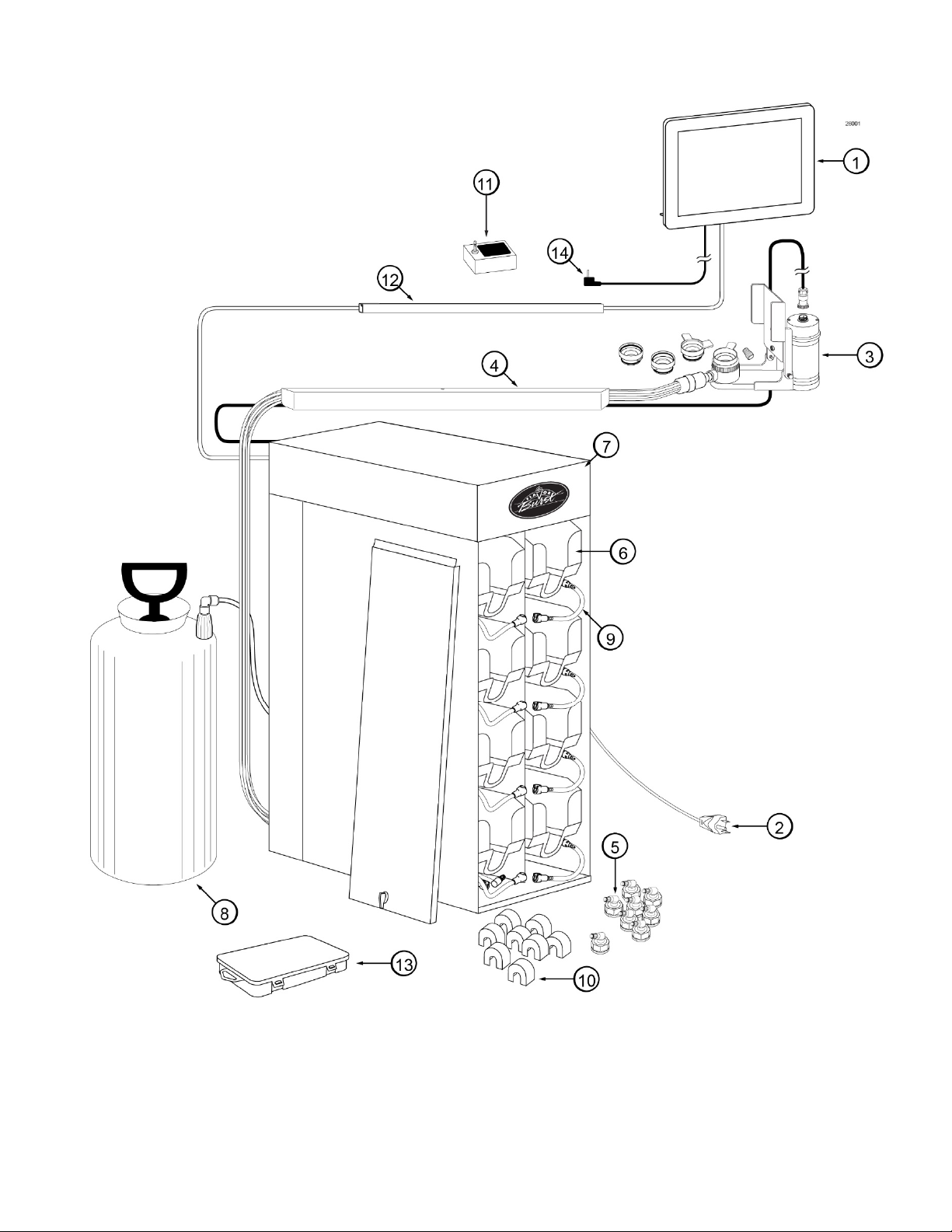
General System Overview
Figure 1
8

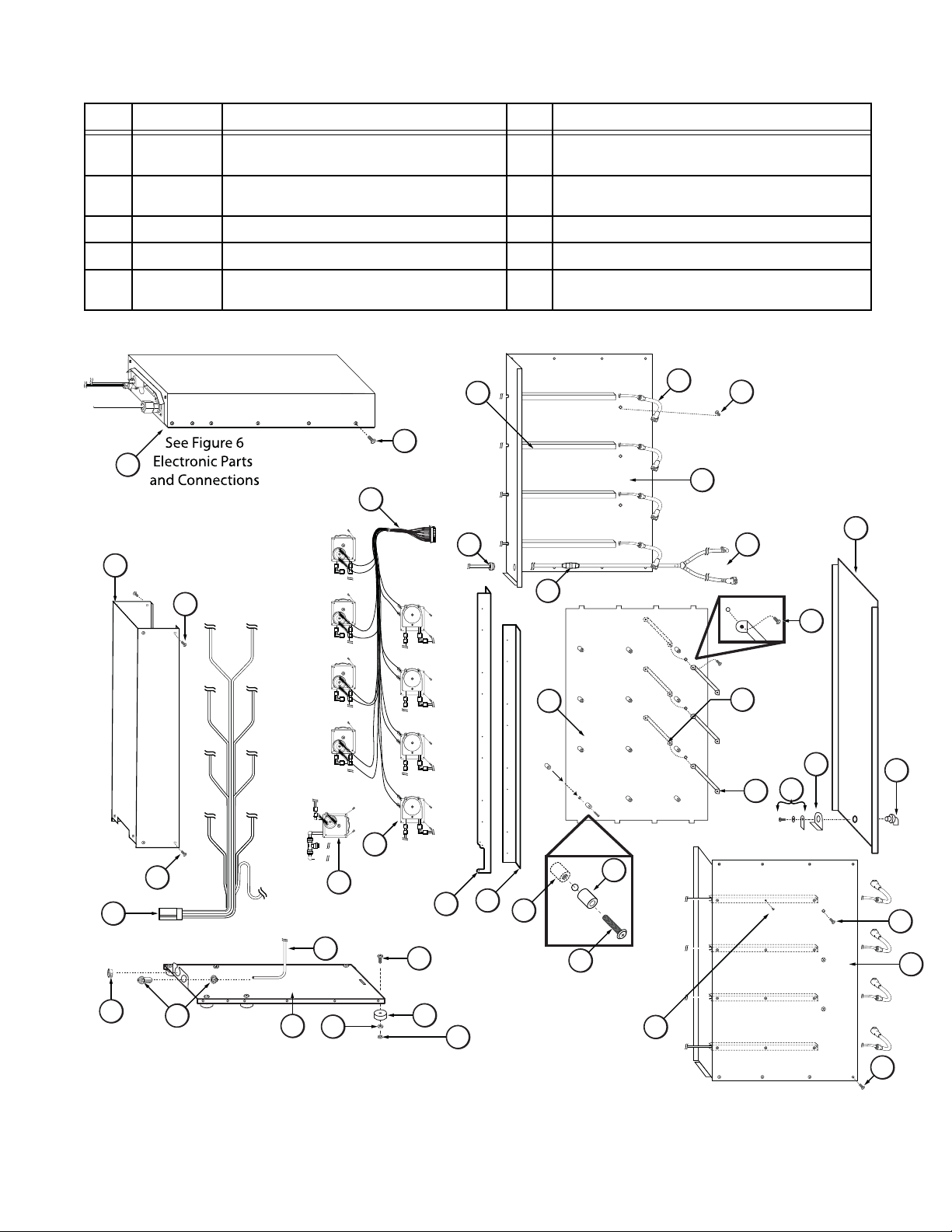
Cabinet – (See Figure 2)
ITEM PART NO. DESCRIPTION QTY. FUNCTION
N/A ELECTRONICS SYSTEM 1 Control system for the unit.
1
CAB 135R-A
2
CAB 145 TRAY SUPPORT BRACKET 8 Supports flavoring trays.
3
FAS 2024 8-32 X 1/4 PAN HEAD 28
4
FAS 2014 8-32 X 1/2" PAN HEAD 25
5
SYR 944
6
ELE 932
7
MIS 3066 MINI BUSHING 1 Protects flush tube.
8
MIS 3028-80
9
CAB 139 FRONT DOOR PANEL 1
10
RIGHT SIDE PANEL 1 Holds tray support brackets and panel brackets.
Fastens panel brackets to divider panel, secures
sides.
Attaches top panel, back cover, and feet to
cabinet.
SYRUP TUBE ASSEMBLY –
SOFT SERVE
PUMP & SANITIZER CABLE
HARNESS
FLUSH TUBE ASSEMBLY 1
Transports the flavoring from the syrup bag to the
8
syrup pump.
1 Provides power to the syrup and sanitizer pumps.
Connects with flavor line to flush with sanitizer
solution.
Provides easy access to syrup bags and
connectors.
CAB 136-A
11
FIX 1023
12
CAB 134 DIVIDER PANEL 1
13
CAB 144R RIGHT PANEL BRACKET 3 Holds tray support rails.
14
CAB 144L LEFT PANEL BRACKET 3 Holds tray support rails.
15
CAB 143 LATCH BRACKET 1 Provides latching tab for front panel latch.
16
FAS 2001 FRONT DOOR PANEL LATCH 1 Latches front door to cabinet front.
17
SYR 927 INTERNAL 9-TUBE ASSEMBLY 1
18
SAN 748 PERISTALTIC SANITIZER PUMP 1
19
SYR 307 PERISTALTIC SYRUP PUMP 8 Pumps syrup from flavor bags into flavor lines.
20
CAB 155L PUMP MOUNTING STRIP 1
21
CAB 155R PUMP MOUNTING STRIP 1
22
FAS 2037 TAPPED NYLON SPACER 12
23
FAS 2032 STANDARD NYLON SPACERS 12 Provides extra support for flavor trays.
24
FAS 2034 8-32 X 3/4" MACHINE SCREW 12 Attaches bushings to divider panel.
25
MIS 3067 OPEN/CLOSED BUSHING 1 Strain relief for internal 9-Tube Assembly.
26
FIX 1033
27
TUB 803 TUBING-PER FOOT 1 Transports sanitizer solution from tank to pump.
28
CAB 133 BASE PANEL 1 Attaches the bottom of the inner and side panels.
29
REAR PUMP COVER 1 Back panel to cover pumps.
3/16" X 3/16" BARB TUBE
CONNECT
1/4" X 1/4" BLKHD (PUSH-TOCONNECT)
1 Splices together flush tubes.
Holds tray support brackets and divides flavor
trays.
Transports syrup from bags to flavor 9-Tube
Assembly.
Pumps sanitizer solution to flush tube and
sanitizer line.
Support for syrup trays and spacing between
panels.
Support for syrup trays and spacing between
panels.
Secures screw to center panel, and support for
trays.
1 Connects Sanitizer Tank tube to the unit.
9
Cabinet (Continued)
ITEM
PART NO. DESCRIPTION QTY. FUNCTION
RUB 618 RUBBER BUMPER WITH WASHER 6
30
FAS 2035 8-32 NUTS - EXT. LOCK WASHER 6
31
MIS 3074 SHORTY PLUG #1672 6 Covers screw hole in rubber bumper.
32
FAS 2040 6-32 X 1/4" TAPPING SCREW 24 Secures tray support bracket to side panels.
33
CAB 135L-A
34
Cabinet
26002
1
11
LEFT SIDE PANEL 1
5
7
5
Provides spacing between cabinet base and
table.
Attaches to screw and holds rubber bumper
in place.
Holds tray support brackets and panel
brackets.
3
8
12
6
4
2
10
9
4
18
26
13
20
4
27
29
28
31
19
5
30
21
32
22
23
24
25
33
14
15
17
16
17
4
34
4
Figure 2
10

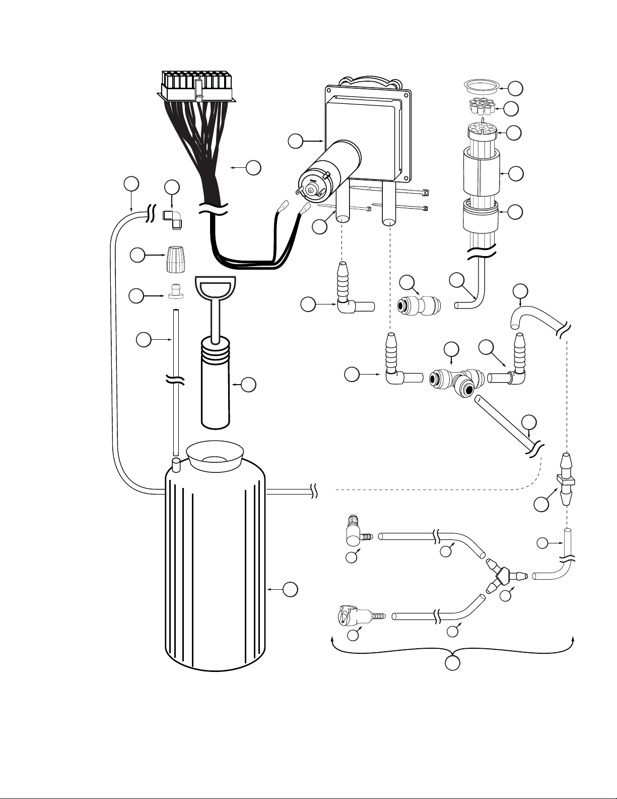
Blending Assembly and Related Parts (See Figure 3)
ITEM PART NO. DESCRIPTION QTY. FUNCTION
FLAVOR BLEND ASSEMBLY WITH
INJ 424BLD
1
INJ 422C BLENDING HEAD ASSEMBLY 1
2
RUB 652-RSS
2A
RUB 651 BLENDING HEAD O-RING 2-020 1 ea. Provides a sealed cavity.
2B
RUB 660 LARGER SYRUP PORT O-RING 1 ea. Provides sealed cavity inside syrup port.
2C
INJ 321C GEAR CARTRIDGE ASSEMBLY 1 Rotates product for even syrup distribution.
3
SYR 932 6' 9-TUBE ASSEMBLY 1
4
FAS 2051 ROLLED FLANGE EYELET 18 ea
4A
ROT 510 LINE COUPLER 2 ea. Holds flavor lines in place.
4B
RUB 610 BAG CONNECTOR O-RINGS 1 ea.
4C
ROT 515-A 9-TUBE ASSEMBLY WAVE SPRING 1 ea. Provides tension between tube connectors.
4D
SYRUP LINES, ADAPTER, &
BRACKET
SMALLER SYRUP PORT O-RING 1 ea. Provides sealed cavity inside syrup port.
1 Transports and blends syrup into product.
Connects flavor line to inject syrups into
product.
Supplies syrup to Blending Head from
pumps.
Provides tension in syrup line to affix to line
coupler.
Provides extra tension between tube
connectors.
INJ 116 LINE COUPLER NUT - BLACK 1 ea. Attaches flavor tubes to flavor manifold.
4E
SYR 901 6' 9-TUBE ASSEMBLY TUBES 9 ea. Brings syrup from pump to Blending Head.
4F
ROT 511 LINE COUPLER NUT 1 ea.
4G
RUB 602 9-POS TUBE CONN. GASKET 1 ea. Provides sealed cavity.
4H
INJ 117
5
MIS 3142 FLAVOR LINE DUST CAP – FB 80 1 Covers syrup manifold when not connected.
6
INJ 201A SYRUP MANIFOLD - BLACK 1 Connects flavor line to Blending Head.
7
RUB 601 9-POS DUCKBILL CHECK VALVE 1
8
MIS 3147
9
MIS 3147A DOOR BRACKET 1 ea. Secures the bracket to the freezer door.
9A
MIS 3147B BASE BRACKET 1 ea. Supports the Blending Assembly Gear Box.
9B
MIS 3147C VERTICAL ADJUSTMENT BRACKET 1 ea.
9C
FAS 2107 THUMB KNOB 2 ea.
9D
FAS 2024 8-32 x 1/4 PAN HEAD SCREW 2 ea.
9E
TUBE CONNECTOR BODY –BLACK
SUSPENSION BRACKET FOR
BLEND ASSEMBLY
Connects flavor lines to the internal 9-Tube
Assembly.
1 Secures flavor line manifold to flavor lines.
Provides sealed cavity and prevents syrup
leakage.
1 Secures Blending Assembly to freezer door.
Secures the door and base brackets and
creates a hinge on the bracket assembly.
Secures the base bracket to the vertical
adjustment bracket.
Secures the door bracket to the vertical
adjustment bracket.
FAS 2177 NYLON LOCKING NUT 2 ea.
9G
10
INJ 330HSB
BLENDING MOTOR ASSEMBLY –
7500 RPM
Secures the suspension bracket to the
blending assembly gear box.
1 Powers Blending system.
11

Blending Assembly and Related Parts (Continued)
ITEM PART NO. DESCRIPTION QTY. FUNCTION
INJ 331
11
FAS 2023
11A
ADPT 8750-A
12
RUB 659
12A
ADPT 8750
12B
RUB 632 BLENDING ADAPTER O-RING 1 ea.
12C
ADPT 101A
13
RUB 642 ADAPTER O-RING 1 ea.
13A
RUB 640 FLAT ADAPTER GASKET 1 ea. Provides sealed cavity inside Adapter.
13B
ADPT 101 BLENDING ADAPTER 1 ea. Attaches Blending Assembly to freezer.
13C
RUB 632 BLENDING ADAPTER O-RING 1 ea.
13D
MIS 3196
14
MIS 3190
14A
MIS 3051
14B
FAS 2040 6-32 x 1/4 PAN HEAD SCREW 1 ea.
14C
FAS 2024 8-32 x 1/4 PAN HEAD SCREW 4 ea.
14D
FAS 2035
14E
ADPT 8750TA
15
ADPT 8750T
15A
RUB 632
15B
ADPT 101TA
16
ADPT 101T BLENDING ADAPTER WITH TAB 1 ea. Attaches Blending Assembly to freezer.
16A
RUB 632
16B
BLENDING GEARBOX
ASSEMBLY
ACCESSORY MOUNTING
BRACKET KNOB
CROWN ADAPTER WITH
O-RINGS
TAYLOR ADAPTER O-RING
8750
CROWN ADAPTER WITOUT
O-RINGS
BLENDING ADAPTER W/ ORINGS
STAINLESS 9-TUBE CASING
ASSEMBLY
STAINLESS 9-TUBE CASING
HINGED CHANNEL
CH-6 CHANNEL MAGNET
ASSEMBLY
8-32 NUTS – EXT. LOCK
WASHER
CROWN ADAPTER ASSEMBLY
WITH TABS
CROWN ADAPTER WITH TABS
WITOUT O-RING
OUTTER O-RING FOR SPOUT
ADAPTER
SPOUT ADAPTER WITH TAB
AND O-RING
OUTTER O-RING FOR SPOUT
ADAPTER
1
1 ea. Secures base Mounting Bracket to Gear Box.
1 Attaches Blending Assembly to freezer door.
1 ea.
1 ea. Attaches Blending Assembly to freezer door.
1 Attaches Blending Assembly to freezer door.
1
1 ea.
2 ea. Holds the Casing Channel to the freezer panel.
4 ea.
1 Attaches Blending Assembly to freezer door.
1 ea. Attaches Blending Assembly to freezer door.
1 ea.
1 Attaches Blending Assembly to freezer door.
1 ea.
Gears turn Gear Cartridge for even syrup
distribution.
Creates tension to secure adapter to freezer
door.
Creates tension to secure adapter to Blending
Head.
Creates tension to secure Adapter to freezer
door.
Creates tension to secure Adapter to Blending
Head.
Protects and holds the cables and 9-Tube
Assembly in place on the freezer side panel.
Covers and protects the cables and tubes of
the Casing Assembly.
Secures the Casing cover to the mounting
brackets.
Secures the magnet assembly to the mounting
brackets.
Secures the magnet assembly to the mounting
brackets.
Creates tension to secure adapter to Blending
Head.
Creates tension to secure Adapter to Blending
Head.
12

PAGE INTENTIONALLY LEFT BLANK
13
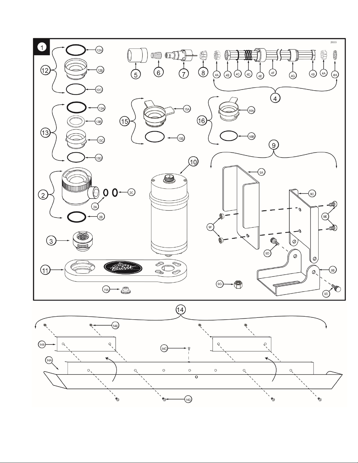
Blending Assembly and Related Parts
Figure 3
14
Syrup Pump and Related Parts (See Figure 4)
ITEM PART NO. DESCRIPTION QTY. FUNCTION
N/A SOFT SERVE SYRUP PUMP 8
1
SYR 307 PERISTALTIC SYRUP PUMP 1 ea.
1A
TUB 806 1/8” SYRUP PUMP REPL TUBE 1 ea. Transports syrup through pump.
1B
FAS 2067 SYRUP PUMP TUBE WASHER-1/4 1 ea. Secures pump tube.
1C
FAS 2066 SYRUP PUMP CLAMP-HOSE-1/4" 1 ea. Prevents pump tube from slipping.
1D
FAS 2051 ROLLED FLANGE EYELET 1 ea. Creates tension for tighter fit.
1E
FIX 1036 1/4" TO 1/4" OD UNION ELBOW 1 ea. Connects syrup in tube to pump.
1F
FIX 1035 1/4 TO 3/16 OD REDUCING UNION 1 ea. Connects syrup pump to flavor line out.
1G
SYR 944
2
FIX 1054 1/4” ID HOSE BARB SHUTOFF 1 ea. Connects flavor line to flavor bag.
2A
SYR 902 FLAVOR-IN TUBE 1 ea. Carries syrup from syrup bag to pump.
2B
TUB 811
2C
FIX 1048 FITTING-1/4X1/4 BARB FB80 1 ea. Connects syrup tube to silicone tube.
2D
SYR 900 4' 9-TUBE ASSEMBLY TUBE 9
3
ROT 511 LINE COUPLER NUT 1
4
ROT 512 TUBE CONNECTOR BODY 1
5
ROT 510 LINE COUPLER 1 Holds flavor lines in place.
6
SYRUP TUBE ASSEMBLY –
SOFT SERVE
TUBE-SILICONE .188X.375 PE
FB80
1 ea. Connects barb fitment to tube port.
Pumps syrup from flavor bags to flavor
lines.
Pumps syrup from flavor bags to flavor
lines.
8 Transports flavor from bag to pump.
Brings syrup from pump to Blending
Head.
Connects flavor lines to the internal
9-Tube Assembly.
Connects internal 9-Tube Assembly to
flavor lines.
FAS 2051 ROLLED FLANGE EYELET 9 Secures flavor lines to line coupler.
7
MIS 3023 FLAVOR LINE DUST CAP 1 Cover to protect end of flavor lines.
8
SYR 941A SYRUP BAG ADAPTER 8 Connects bag fitment to flavor lines.
9
SYR 940 SYRUP BAG ADAPTER CAP 1 ea. Attaches to flavor bag fitment.
9A
SYR 939B
9B
RUB 662 SYRUP BAG ADAPTER O-RING 1 ea.
9C
CAB 113 FLAVORING TRAY 8 Houses syrup bags.
10
ELE 932
11
SYR 946 SYRUP BAG LOCK 8 Secures the syrup bag fitments to the tray.
12
SYRUP BAG ADAPTER VALVE
ASSEMBLY
PUMP & SANITIZER CABLE
HARNESS
1 ea. Transports syrup to quick connect fitment.
Provides sealed cavity for Syrup Bag
Adapter.
Provides power to the syrup and sanitizer
1
pumps.
15
Syrup Pump and Related Parts
26004
2
1
1A
11
1B
1C
1G
1D
1E
2A
2C
2D
2B
1F
9
9A
9B
9C
4
5
6
8
7
3
10
12
Figure 4
16

Sanitizer Pump and Related Parts (See Figure 5)
ITEM PART NO. DESCRIPTION QTY. FUNCTION
SAN 748 SANITIZER PUMP ASSEMBLY 1 Supplies sanitizer to flush tube.
1
TUB 807 SANITIZER TUBE REPLACEMENT 1 Transports sanitizer through pump.
2
MIS 3023 DUST CAP 1 Cover to protect end of flavor lines.
3
Creates tension for tighter fit 1 per
pump, 9 per tube assembly.
Connects internal 9-Tube Assembly to
flavor lines.
Connects flavor lines to the internal
9-Tube Assembly.
Transports syrup and sanitizer from
pumps to Blending Assembly.
Connects sanitizer line to flush adapter
and pump lines.
Connects with flavor line to flush with
sanitizer solution.
Connects to the syrup bag adapter to flush
sanitizer solution through it.
Connects to the syrup line to flush sanitizer
solution through it.
Transports sanitizer to Pump Flush Adapter
fitments.
Transports sanitizer solution from tank
to sanitizer pump.
Holds sanitizer tube in place and seals
tank hole.
Seals Sanitizer Tank and adds pressure
1
when needed.
Provides power to the syrup and sanitizer
1
pumps.
10
11
12
13
14
14A
14B
14C
14D
15
16
17
18
19
20
21
22
FAS 2051 ROLLED FLANGE EYELET 9
4
ROT 510 LINE COUPLER 1 Holds flavor lines in place.
5
ROT 512 TUBE CONNECTOR BODY 1
6
ROT 511 LINE COUPLER NUT 1
7
SYR 900 4' 9-TUBE ASSEMBLY TUBES 9
8
FIX 1035 1/4 TO 3/16 OD REDUCING UNION 1 Connects elbow to sanitizer line.
9
FIX 1042 TUBE-TO-TUBE ELBOW 3 Connects pump tube to reducing union.
SYR 931 CLEAR TUBING 1 Transports sanitizer to Pump Flush Adapter.
SAN 701 SANITIZER TANK 1 Holds sanitizer solution.
FIX 1053 SANITIZER PUMP T CONNECTOR 1
MIS 3028-80
FIX 1054 1/4” ID HOSE BARB SHUTOFF 1 ea.
FIX 1051 1/4” ID HOSE BARB ELBOW 1ea.
SYR 931 CLEAR TUBING 3 ea.
FIX 1046 FLUSH TUBE “Y” CONNECTOR 1 ea. Splits sanitizer flush tube into two tubes.
FIX 1023 3/16" X 3/16" BARB TUBE CONNECT 1 Splices together flush tubes.
TUB 803 .17 x 1/4 LDPE TUBING-PER FOOT 1
FIX 1036 1/4" TO 1/4" OD UNION ELBOW 1 Connects sanitizer tube to supply tube.
SAN 715 SUPPLY TUBE CAP 1 Fastens grommet securely to tank.
RUB 615 FEEDER TUBE RUBBER GROMMET 1
SYR 902 SANITIZER SUPPLY TUBING 1 Supplies sanitizer from Sanitizer Tank.
SAN 734
ELE 932
FLUSH TUBE ASSEMBLY 1
HAND PUMP ASSEMBLY-FLUTED
TANK
PUMP & SANITIZER CABLE
HARNESS
17
Sanitizer Pump and Related Parts
26005
3
4
16
18
19
20
17
21
22
1
5
6
7
2
9
8
11
10
13
10
10
16
15
14C
12
14B
14A
14C
14D
14C
14
Figure 5
18

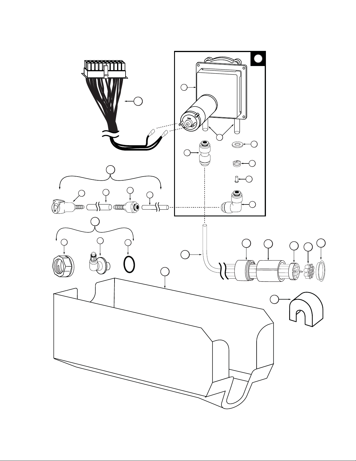
Electronic Parts and Connections (See Figure 6)
ITEM PART NO. DESCRIPTION QTY. FUNCTION
ELE 905 FLAVOR 10 COLOR TOUCH PANEL 1 Control system for the unit.
1
MIS 3214
2
MIS 3214A TOUCH PANEL MOUNTING PLATE 1 ea.
2A
MIS 3214B MOUNTING ANCHOR BRACKET 1 ea. Allows the bracket to be angled up or down.
2B
MIS 3214C MOUNTING BASE PLATE 1 ea.
2C
FAS 2170 M4 X 8 PHILLIPS SCREW 4 ea.
2D
FAS 2174 1/4 - 20 NYLON LOCK NUT S.S. 2 ea.
2E
MIS 3076 ADHESIVE PAD 1 ea. Secures the mounting bracket to the freezer.
2F
FAS 2172 1/4-20 X 1/2 HEX BOLT 2 ea.
2G
FAS 2023 MOUNTING BRACKET KNOB 4 ea. Secures anchor bracket to the base plate.
2H
FAS 2171 M4 LOCK WASHER 4 ea.
2I
FAS 2173 FLAT WASHER 18-8 S.S. 2 ea. Secures connection between bolt and nut.
2J
ELE 924 WIRELESS SPIGOT SWITCH 1
3
MIS 3026S
4
ELE 525M
5
CAB 137-A ELECTRONICS COVER 1
6
FAS 2014 8-32 X 1/2" PAN HEAD 16 Secures various parts within the top of unit.
7
MIS 3150 FLAVOR BURST LOGO DECALS 1 Displays Flavor Burst trademark logo.
8
CAB 156 CONNECTOR SHIELD 1 Protects power cables from liquids.
9
10
ELE 485CTP
ELE 932
11
ELE 933 POWER SUPPLY JUMPER CABLE 1
12
ELE 931 EXTERNAL ROTOR CABLE 1
13
14
INJ 330HSB
ELE 911 ELECTRONICS BOARD 1 Provides power to the system.
15
FAS 2024 8-32 X 1/4 PAN HEAD SCREW 3 Secures power supply to the base panel.
16
FAS 2035 8-32 NUTS - EXT. LOCK WASHER 5
17
FAS 2175 M3.5 NUT - EXT. LOCK WASHER 1
18
TOUCH PANEL MOUNTING BRACKET
ASSEMBLY
TOUCH PANEL CABLE CASING
MALE TO MALE 48” SWITCH
EXTENSION
120V POWER ENTRANCE MODULE 1
PUMP & SANITIZER CABLE
HARNESS
BLENDING MOTOR ASSEMBLY –
7500 RPM
1 Secures the Touch Panel to the freezer.
1
1 ea. Connects Touch Panel to the freezer switch.
1 Provides power to syrup & sanitizer pumps.
1 Supplies power to Motor which turns gears.
Attaches the Touch Panel to the anchor
bracket.
Creates a mounting base for the bracket
assembly.
Secures the mounting plate to the Touch
Panel.
Secures the anchor bracket in a fixed
position.
Hinges Touch Panel plate and anchor
bracket.
Secures connection between screw and
plate.
Sends a wireless signal to the Touch Panel
when the freezer draw handle is activated.
Conceals and protects the Touch Panel
cable, as well as attaches it to the freezer.
Protects and covers electronics
microprocessor.
Provides a power connection to the outside
of the cabinet.
Connects the power supply to the electronics
board.
Connects the drive motor to the back of the
cabinet.
Secures ground wire to screw and
Panel and the Electronics Box to the panel.
Secures the power entrance module ground
wire to the board.
19
Electronic Parts and Connections (Continued)
ITEM PART NO. DESCRIPTION QTY. FUNCTION
ELE 930 INTERNAL ROTOR CABLE 1
19
FAS 2008 4-40 X 3/8" PAN HEAD SCREW 4 Attaches the ethernet plate to the panel.
20
MIS 3216 CLOSURE PLUG 5/8 INCH 2 Closes up extra opening in the base panel.
21
ELE 434 POWER CABLE 1 Supplies the electronics board with power.
22
ELE 927 RJ45 ETHERNET CABLE GLAND 1 Secures the Ethernet cable to the cabinet.
23
ELE 925 RJ45 EHTERNET CABLE - EXTERNAL 1 Connects the Touch Panel to the cabinet.
24
ELE 926 RJ45 ETHERNET CABLE - INTERNAL 1
25
CAB 138TS ELECTRONICS BASE PANEL 1 Secures electronics board.
26
FAS 2042 4/40 LOCK NUT 4 Secures the Ethernet plate and screws.
27
MIS 3004
28
CTP ETHERNET CABLE PLATE
Connects the external rotor cable to the
electronics board.
Connects the Ethernet cable to the
electronics board.
Converts the touchscreen cable hole to an
1
ethernet cable hole.
20

PAGE INTENTIONALLY LEFT BLANK
21
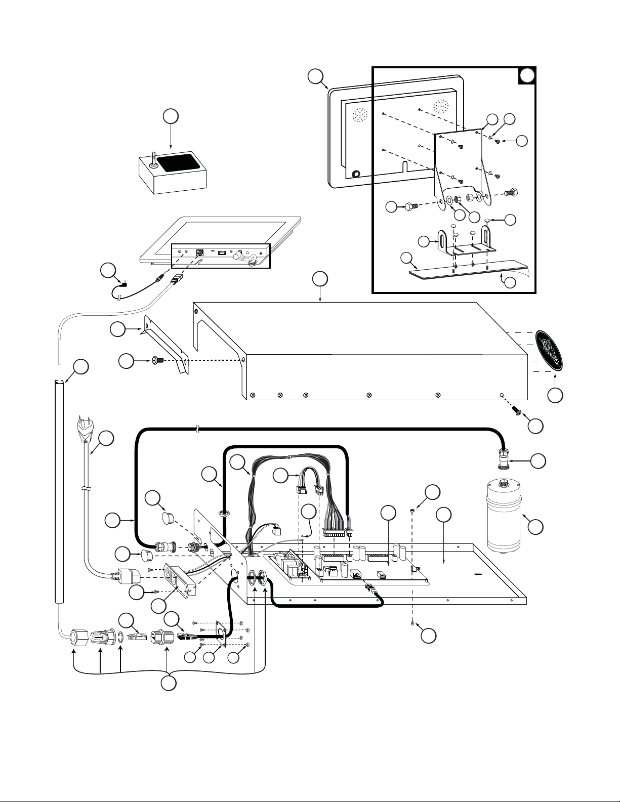
Electronic Parts and Connections
1
2
3
2G
2B
2C
5
6
2J
2E
2I
2A
2D
2H
2F
9
4
7
8
22
11
19
12
21
18
13
21
7
10
24
25
20
28
27
23
Figure 6
15
7
13
17
26
14
16
22