

Page 1
Sophia Slimline
BF
BALANCED FLUE LOG EFFECT GAS FIRE
Installation, Maintenance & User Instructions
Hand these instructions to the user
Model No’s FSBL**RN is only for use on Natural Gas (G20) at a
supply pressure of 20 mbar in G.B. / I.E.
** denotes cosmetic variant
Page 2

Information Requirements for Commission Regulation (EU) 2015/1188
Model Identifier FSBL**RN
Indirect Heating Functionality No
Direct Heat Output 4.3kW
Indirect Heat Output Not Applicable
Fuel NG (G20)
NOx Emissions 130mg/kWh
Nominal Heat Output 4.3kW
Minimum Heat Output (Indicative) 1.3kW
Useful Efficiency at Nominal Heat Output 87.2%
Useful Efficiency at Minimum Heat Output 50.0%
(Indicative)
Auxilliary electrical power consumption at 0.0000008kW
nominal heat output
Auxilliary electrical power consumption at 0.0000008kW
heat output
Auxilliary electrical power consumption at 0.0000008kW
standby mode
Permanent pilot flame requirement 0.213kW
Type of heat output / room temperature With electronic room temperature
control plus day timer.
Contact Details BFM Europe Ltd.
Gordon Banks Drive
Trentham Lakes North
Stoke-on-Trent
ST4 4TJ
Tel : 01782 339000
Page 3

CONTENTS
P
AGE
S
ection 1 Information and Requirements
1
.0 Appliance Information 3
1
.1 Conditions of Installation 4
1.2 Fireplace surround & suitability 4
1.3 Flue Terminal Position 5
1
.4 Shelf position 6
1.5 Hearths 6
Section 2 Installation of Fire
2.1 Unpacking the fire 6
2.2 Fireplace opening 7-8
2.3 Preparation of the wall 8-9
2.4 Preparation of the flue hole 9
2.5 Installation of the gas supply 10
2.6 Preparation of the flue duct 11
2.7 Securing the firebox to the opening 12-13
2.8 Installing the “Sophia” surround 14-15
2.9 Making the gas connection / pressure testing 16
2.10 Fitting the batteries 16
2.11 Removal & refitting of the glass frame 17-19
2.12 Fitting the terminal guard 19
2.13 Removal & refitting of the burner assembly 20-21
Section 3 Assembling Fuel Bed and Commissioning
3.1 Fitting the log fuel bed 22-26
3.2 Lighting the appliance 27-30
3.3 Fitting the handset wall bracket 31
3.4 Instructing the user / product handover 31
Section 4 Maintenance
4.1 Removal of the burner assembly 32
4.2 Removal of the gas valve 32
4.3 Removal of the pilot assembly 33
4.4 Replacement of handset batteries 33
4.5 Replacement of the batteries in the fire 33
4.6 Removal of the control board / receiver unit 33
4.7 Parts shortlist 34
Section 5 User Instructions
5.1 Conditions of Installation 42
5.2 About your new fire 43
5.3 Operating the fire 44-49
5.4 Removal / re-fitting the glass frame assembly 50-52
5.5 Removal / replacement of the fuel-bed 53-56
5.6 Cleaning the fire 57-58
5.7 User replaceable parts 58
5.8 Removing / replacing the batteries 58
This appliance is manufactured by :-
BFM Europe Ltd, Trentham Lakes,
Stoke-on-Trent, ST4 4TJ.
2
Page 4
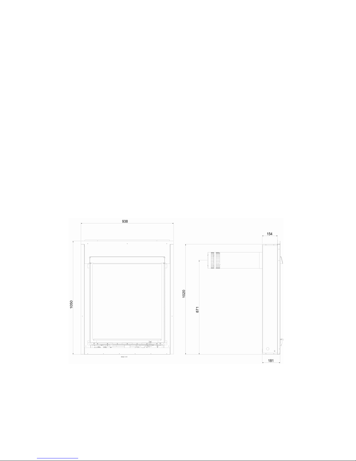
SECTION 1
INFORMATION AND REQUIREMENTS
1.0 APPLIANCE INFORMATION
M
odel FSBL**RN
** denotes cosmetic variant of product
Gas Type G20
M
ain injector (1 off) Size 1.70mm
P
ilot Type Black Technigas “Polidoro” G27.2
M
ax. Gross Heat Input : 5.5 kW
Min. Gross Heat Input : 2.5 kW
Gas Rate : 0.511 m3/hr
Cold Pressure : 20.0 +/-1.0 mbar
Electrode Spark Gap 4.0mm
Packed Weight 80.5kg
Gas Connection : 8mm Compression (supplied with fire)
Fig. 1
3
Page 5

INSTALLATION REQUIREMENTS
Efficiency Declaration
The efficiency of this appliance has been measured as specified in
BS EN 613 : 2001 and the result after conversion to Gross using the
appropriate factor from Table 4 of SAP 2009 is 78%. The test data from which it
has been calculated has been certified by BSI. The efficiency value may be used
in the UK Government’s Standard Assessment Procedure (SAP) for energy rating
of dwellings.
1.1 CONDITIONS OF INSTALLATION
It is the law that all gas appliances are installed only by a GAS SAFE Registered
Installer, in accordance with these installation instructions and the Gas Safety
(Installation and Use) Regulations 1998 as amended. Failure to install appliances
correctly could lead to prosecution. It is in your own interest and that of safety to
comply with the law.
The installation must also be in accordance with all relevant parts of the Local and
National Building Regulations where appropriate, the Building Regulations
(Scotland Consolidation) issued by the Scottish Development Department, and all
applicable requirements of the following British Standard Code of Practice.
1. B.S. 5871 Part 1 Installation of Gas Fires
2. B.S. 6891 Installation of Gas Pipework
3. B.S. 5440 Parts 1 & 2 Installation of Flues and Ventilation
4. I.S 813 : 1996 Domestic Gas Installation, issued by the National Standards
Authority of Ireland.
1.2 FIREPLACE / SURROUND SUITABILITY
The fire must only be installed with the surround supplied it must not be installed
directly onto carpet or other combustible floor materials.
If a heating appliance is fitted directly against a wall combustible material must be
removed from behind it. Soft wall coverings such as blown vinyl, wall paper etc.
could be affected by the rising hot air and scorching and/or discoloration may
result. Due consideration should be made to this when installing or decorating.
This product can only be installed with the surround design supplied by the
manufacturer or designs which meet the criteria as required by BFM Europe.
For further details of specification requirements please contact BFM Europe
Technical Service.
4
Page 6
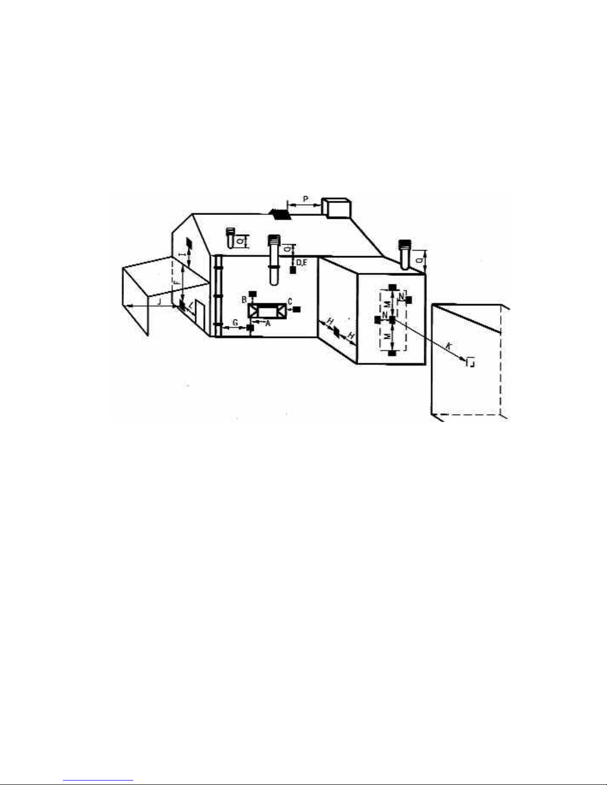
1.3 FLUE TERMINAL POSITION
The minimum acceptable dimensions from the flue terminal to obstructions
and ventilation openings are shown below and listed in the table
It is important that the position of the flue allows the free passage of air
across it at all times. The minimum acceptable space from the flue terminal
to obstructions and ventilation openings are specified below (figure 2).
Fig. 2
DIMENSION TERMINAL POSITION MINIMUM DIMENSION
A Directly below an opening, air brick, 300mm (12in)
opening window
B Above an opening, air brick, 300mm (12in)
opening window
C Horizontally to an opening, air brick, 300mm (12in)
opening window etc.
D Below gutters, soil pipes or drain pipes 300mm (12in)
E Below eaves 300mm (12in)
F Below balconies or car port roof 600mm (12in)
G From a vertical drain pipe or soil pipe 300mm (12in)
H From an internal or external corner 600mm (24in)
I Above ground roof or balcony level 300mm (12in)
J From a surface facing the terminal 600mm (24in)
K From a terminal facing the terminal 600mm (24in)
L From an opening in the car port 1200m (48in)
M Vertically from a terminal on the same wall 1500mm(59in)
N Horizontally from a terminal on the 300mm (12in)
same Wall
O NOT APPLICABLE N/A
P NOT APPLICABLE N/A
Q NOT APPLICABLE N/A
5
Page 7

1.4 SHELF POSITION
This fire must not be fitted below combustible shelf materials.
1.5 HEARTHS
This appliance must only be installed with the Flavel Sophia Slimline hearth panel
or an alternative item as dimensionally approved by BFM Europe.
SECTION 2
INSTALLATION OF FIRE
2.1 UNPACKING THE FIRE
Carefully lift the fire out of the carton. Remove the loose item packaging carefully
from the front of the appliance. Check the contents as listed :-
Packing Check List - All Models
Pack 1 of 2 - Combustion Chamber Pack
1 off Combustion chamber & glass frame assembly
1 off Boxed ceramic fuel-bed set (packed inside combustion chamber)
1 off Wall plate
1 off Flue terminal / pipe unit
1 off Flue terminal guard (packed inside combustion chamber)
1 off Installation / user book (combined)
1 off Guarantee card
1 off Front grill (painted)
1 off Loose items pack – containing :- 1 off standard fixing kit
1 off 9V PP3 battery
4 off AA batteries
1 off thermostatic remote handset
wall bracket and fixings
4 off 8mm rawlpugs & fixing screws
1 off length of foil tape 500mm
4 off 8mm nylon plugs
4 off 30mm wood screws
2 off surround securing brackets
Pack 2 of 2 - Sophia Surround 1 off glass removal tool
1 off Hearth 1 off L/H leg
1 off Shelf 1 off R/H leg
1 off Top infill 1 off Shelf infill section
1 off Firebox / burner assembly 2 off Side infill sections
1 off Bottom infill section 2 off shelf brackets
2 off Shelf infill brackets 2 off Leg brackets
6
Page 8
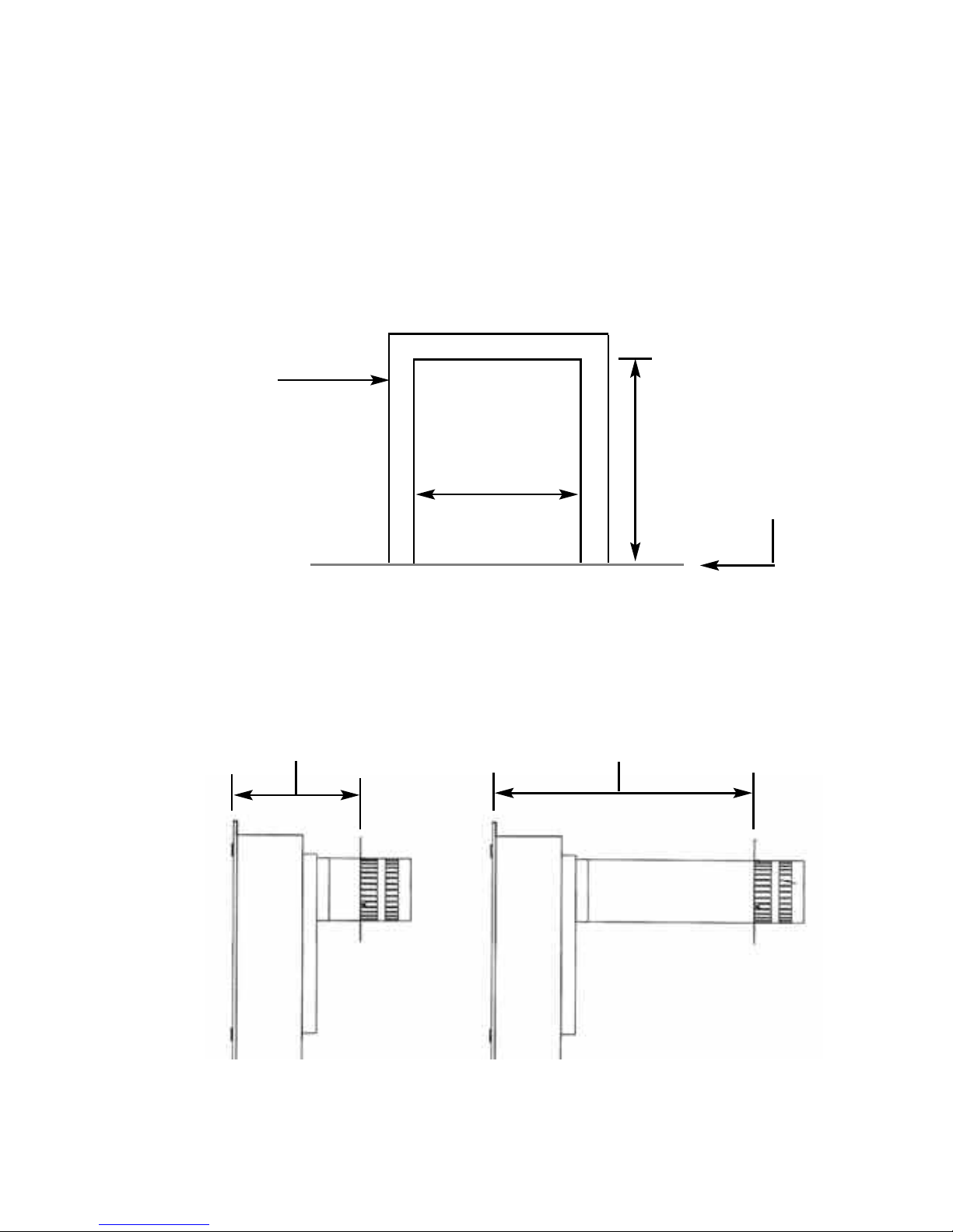
2.2 FIRE PLACE OPENING
2.2.1 The front opening of the fire place must be between 750 and 840mm
wide and between 1025mm and 1050mm high. If the opening exceeds
these dimensions then a surround must be constructed from suitable
non-combustible material to produce a suitable sized opening. Any
surround must be suitably sealed to the fire place to prevent leakage.
See figure 3 below.
Fig. 3
2.2.2 The minimum / maximum sized distances between the firebox mounting
flange and outside wall are shown below and overpage in figure 4 & 5.
Fig. 4
7
750mm minimum,
840mm maximum
Fire Opening
1025mm minimum,
1050mm maximum
Minimum Flat
Sealing Area
10mm
Minimum Installation
Depth 254mm
Maximum Installation Depth
554mm
Level of bottom of
hearth panel /
firebox
Page 9
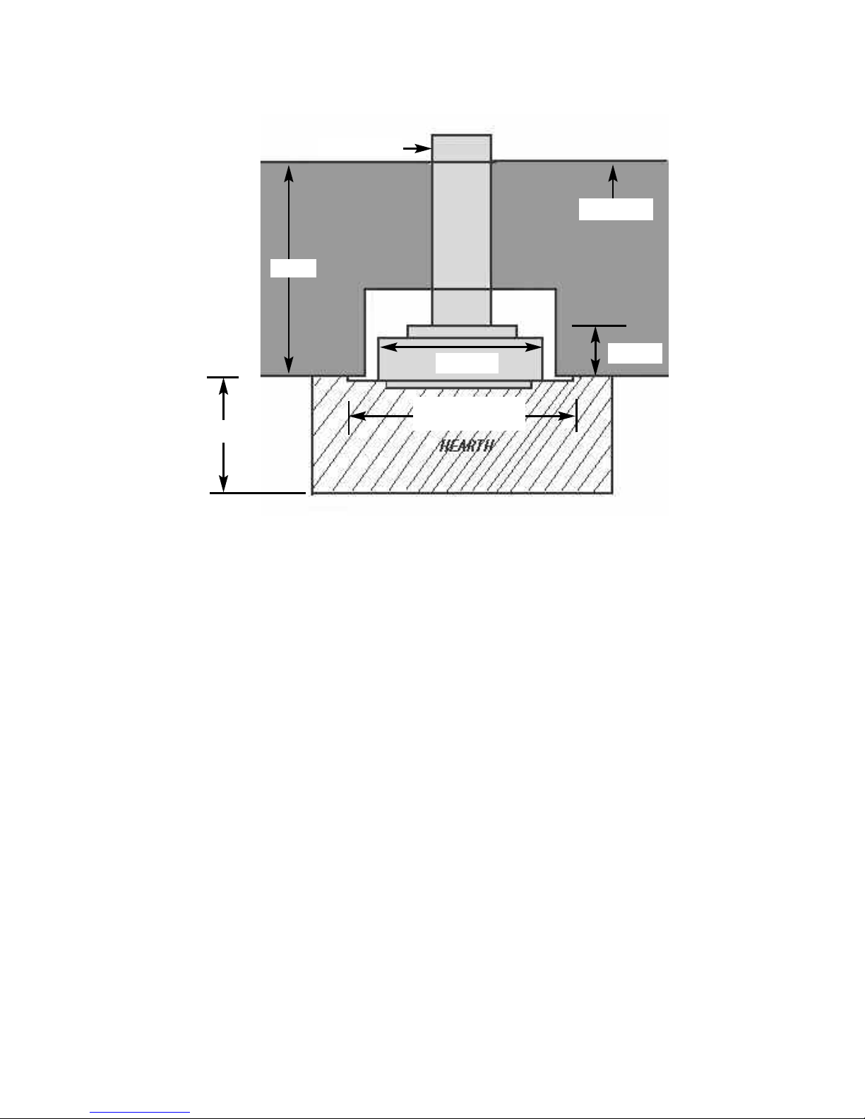
Fig. 5
2.3 PREPARATION OF THE WALL
2.3.1 The appliance and flue pipes must be installed at right angles to the
mounting wall. The appliance itself should be installed vertically against
a flat wall. Where an uneven wall surface is found, appropriate action
should be taken to ensure that the appliance is not stressed or does not
distort when installed.
2.3.2 Ensure that the floor surface onto which the appliance is mounted onto
is flat. The minimum height from the floor to the centre of the flue is
shown on figure 6 overpage.
8
746mm
154mm
O
uter Wall
938mm Including
Firebox Flanges
300mm
Cavity
F
lue Terminal
Page 10
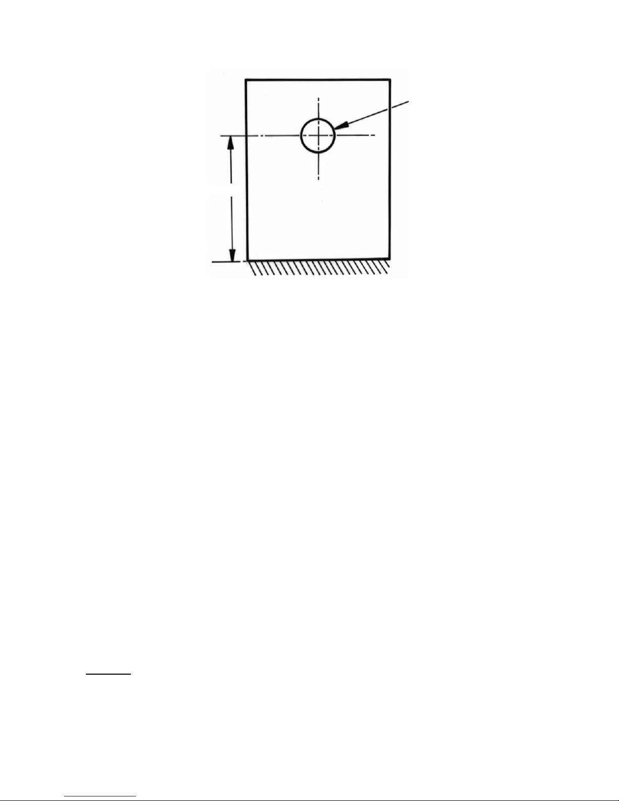
Fig. 6
2.4 PREPARATION OF THE FLUE HOLE
2.4.1 Mark the position of the centre of the flue on the inner wall.
2.4.2 Cut hole for outer flue pipe. There are two possible methods to achieve
this, either core drill or via hammer and chisel.
2.4.3 To core drill, proceed as follows :-
Drill a pilot hole through the wall, in position as specified in figure 6.
Using a 6” core drill, drill the flue hole.
To Hammer and chisel, proceed as follows :-
Mark the position of the centre of the flue pipe as specified in figure 6.
Mark the position of the hole around this point.
Chisel out the area as marked on the wall.
2.4.4 We then recommend that a cardboard cylinder is placed around the flue
pipe and inserted in the chiselled out hole whilst making good.
NOTE :-
If the appliance is to be installed into a building under
construction, it is recommended that a non-corrosive metal
tube of 6” diameter be inserted into the position of the hole.
9
150mm diameter
870mm
Page 11
2.5 INSTALLATION OF THE GAS SUPPLY
2.5.1 Before installing the firebox, decide from which side or if a rear
connection to the gas supply is required. Plan the pipe run to enter the
firebox from the left, right or rear and connect to the inlet elbow. See
below :-
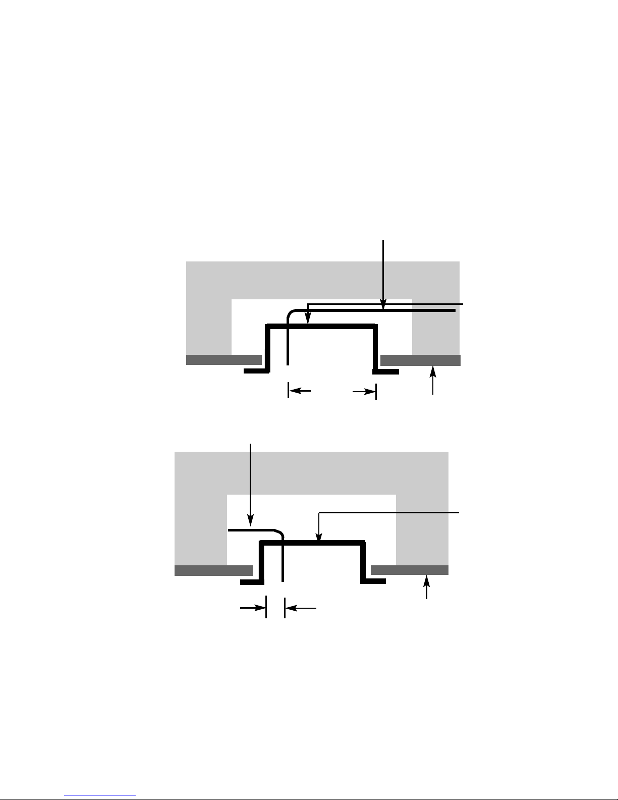
2.5.2 If concealed pipe work is required plan the pipe run to enter the fire box
through the opening in the rear of the fire box and connect to the inlet
elbow. See section 2.13 for burner removal to obtain access to the inlet
elbow cover plate. See figure 7 & 8 below for a suggested concealed
pipe layout.
Fig. 7
Fig. 8
Note : Before breaking into the gas supply a pressure drop test should be
carried out to establish that the existing pipework is sound.
10
Firebox
Fireplace
Gas Supply
Firebox
Approx.
525mm
Fireplace
Gas Supply
Approx.
100mm
Page 12
2.6 PREPARATION OF THE FLUE DUCT
2.6.1 Place the firebox into the fire opening with fire surround correctly
secured in the final position. From the outside of the house measure
from the face of the outside wall to the rear panel of the firebox through
the flue hole. Cut the flue duct to this size.
IMPORTANT : ENSURE THE PIPES ARE CUT SQUARELY.
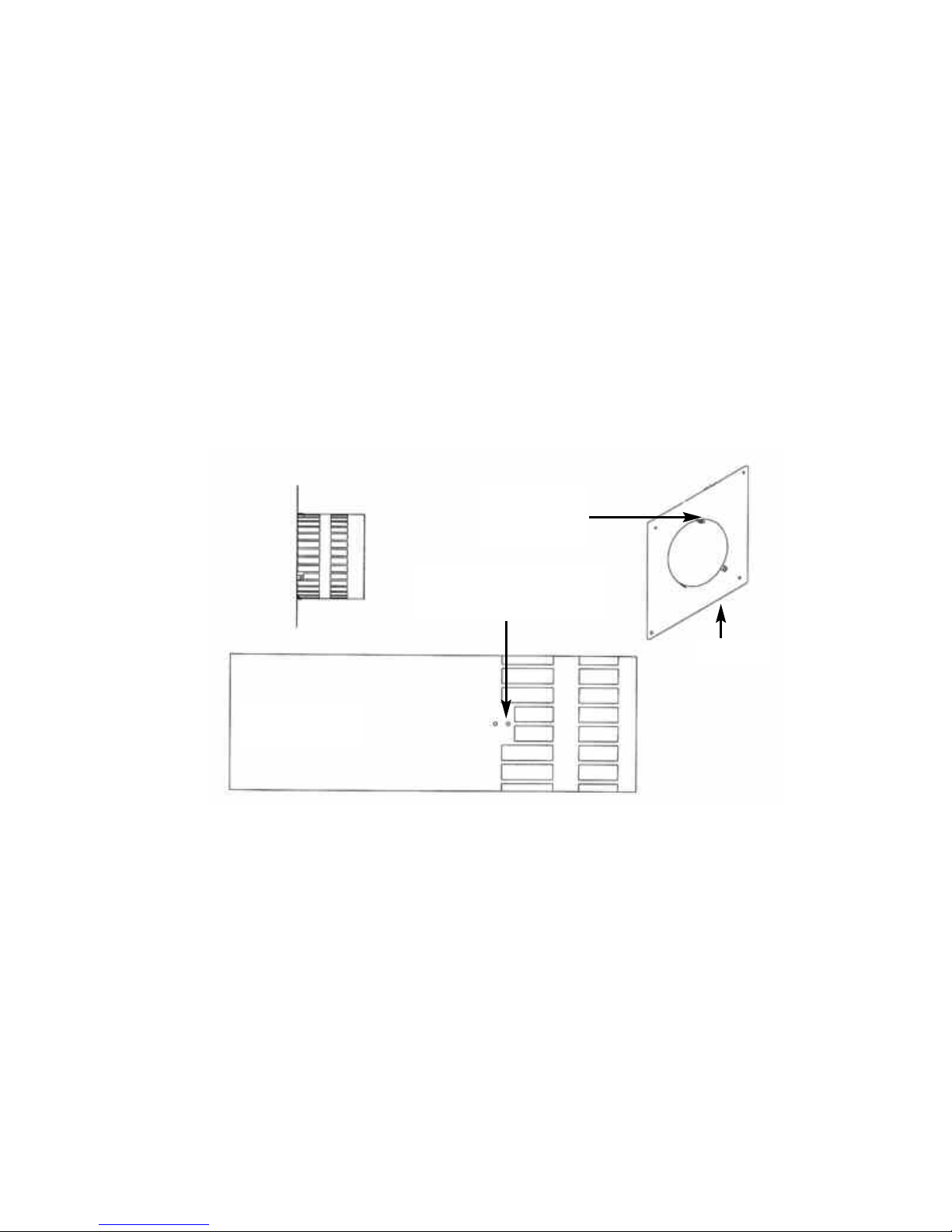
2.6.2 The joint between the firebox and the flue duct as shown below in figure
9 must be secured with screws and sealed with the foil tape as
supplied. In order to do this, the wall plate must removed from the flue
pipe / termination.
Fig. 9
2.6.3 Due to the varying lengths of flue that will be required via differing
installations it will be necessary to drill the flue pipe using the 3 off holes
in the mounting flange on the rear of the combustion chamber as a
guide for positioning. When the holes have been drilled and the screws
fitted, wrap the joint with the foil tape supplied.
2.6.4 Re-fit the wall plate ensuring the outer set of holes as indicated above
in figure 9 are used. Use a high temperature sealant to secure the wall
plate to the outside wall of the property before securing with the screws
and rawlplugs supplied to ensure a mechanical fix.
Lug as shown
should be fitted
uppermost
Wall Plate
Flue
Termination / Pipe
Use the outer set of holes to
secure the wall plate to the
flue pipe / termination
11
Page 13
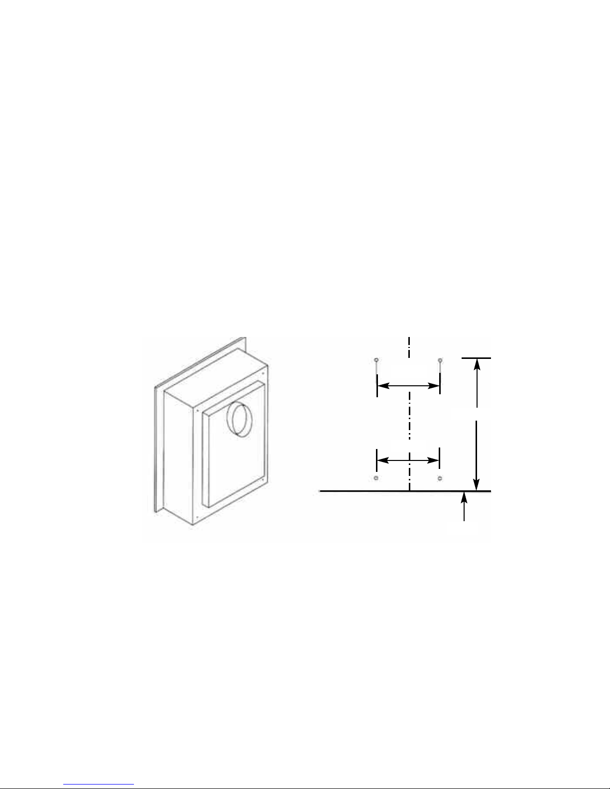
2.7 SECURING OF FIREBOX TO THE OPENING
2.7.1 There is a choice of methods of fixing the firebox that are provided to
enable the installer to deal with any type of installation. The preferred
method of fixing the appliance is the cable fixing method, which is
described in detail in the following section.
2.7.2 If the standard firebox fixing flange is to be used, the firebox may be
secured using the cable method, but in installations where the cable
method is not suitable, e.g.insufficient space behind the firebox, or
loose masonry, the firebox can be fitted directly to either the front of the
fireplace via the flange with the four off screws provided. The firebox will
require sealing to the fireplace, regardless of the method used.
2.7.3 To secure the fire using the preferred cable method, proceed as follows
below :-
2.7.4 Mark out and drill 4 off No 14 6mm holes in the rear face of the fire
opening in the positions as shown in figure 10 below.
Fig. 10
2.7.5 Fit the wall plugs provided and screw the fixing eyes securely into the
rear of the fire opening. Remove the glass frame and burner assembly
as detailed in section 2.11 / 2.13.
2.7.6 Uncoil the two fire fixing cables and thread one end of the each of the
cables through the ears in the top of the fire box lid, and through each
fixing eye at the top. (Removing the top closure plate may improve
access). Thread both cables through the fixing eye’s at the bottom,
then the holes at the bottom of the firebox.
2.7.7 Thread the cables through the rear of the firebox, insert the flue pipe /
terminal through the hole in the rear of the opening and offer the firebox
12
640mm
1000mm
40mm
400mm
Page 14

up to the fireplace.
2.7.8 Thread a tensioning screw over both of the cables and ensure that the
tensioning nut is screwed fully up against the hexagon shoulder of the
tensioning screw (this provides maximum travel for the tensioning nut).
2.7.9 Fit a screwed nipple on to each of the cables and pull hand tight up
against the tensioning screw, then secure each nipple with a
screwdriver.
2.7.10 Before making the final gas connection, thoroughly purge the gas
supply pipework to remove all foreign matter, otherwise serious
damage may be caused to the gas control valve on the fire.
Failure to purge the gas supply will invalidate the guarantee.
13
Page 15

2.8 INSTALLING THE SOPHIA SURROUND
2.8.1 Unpack the surround from the wooden crate, check all parts are present
as per figure 11 overpage and carefully store the components.
2.8.2 The underside of the hearth should be painted with a weak PVA (8 parts
water to 1 part PVA). This will prevent staining penetrating through the
stone. The hearth must be centered to the opening. If the fireplace is
to be installed on a chimney breast ensure that the opening is also
centered to the chimney breast. It is essential that the hearth is
completely level. The hearth must be bedded down on bonding or an
equivalent material. Avoid cement based products and ensure the
hearth is firmly fitted and well supported. Allow the bedding material to
set before any weight is placed onto the hearth. Wipe off any surplus
bonding material with a wet sponge.
2.8.3 Fit brackets to top of legs, offer leg up to wall and mark position of fixing
hole on wall, use shelf to ensure legs are correctly spaced / positioned.
Remove shelf then cover hearth with dust sheet and drill the fixing
holes. Remove the brackets from the legs, fix the side infills into place
with suitable adhesive and secure the leg fixing brackets only to the
wall. Fit legs to brackets that have been securely attached to the wall
with fixings as detailed in 2.8.4
2.8.4 Assess the wall onto which the fire is to be installed and ensure
that it is of sound construction and suitable for supporting the
weight of the surround. Fixings used to secure the leg brackets to
the masonry of the chimney breast shall be of expansive stainless
steel or galvanised steel type masonary fixings for dense concrete
blockwork or brickwork. Where fixings are located into light
weight blockwork or friable aggregrate blocks, the fixings shall be
of the resin anchor type.
2.8.5 Fix the shelf top infill section and shelf infill into place again utilising the
same procedure as for the legs, i.e. mark positions, drill holes to suit,
remove brackets and secure brackets to wall with suitable fixings as
detailed in 2.8.4.
2.8.6 Fit shelf top section into place ensuring it is correctly centered, mark the
position of holes for securing brackets on wall, remove shelf and drill
wall and insert fixings in accordance with 2.8.4, these brackets can be
recessed if required.
2.8.7 Once the fireplace is correctly installed, grout all of the joints including
between the fireplace and the wall with a water based cream mastic or
tile grout. Ensure all surplus grout is immediately removed by washing
the stonework using a sponge and clean water. Ensure all surplus grout
is immediately removed by washing the stonework using a sponge and
clean water.
14
Page 16
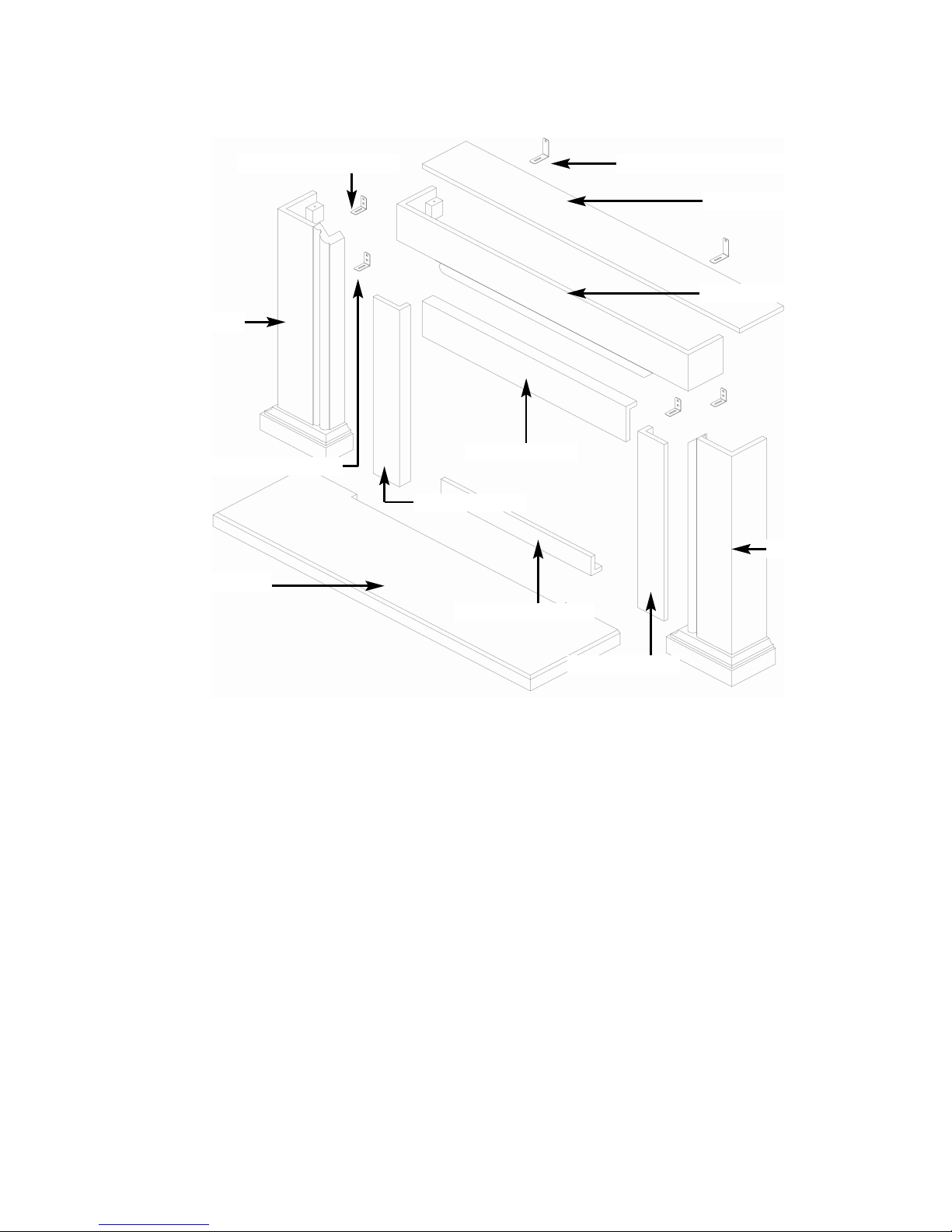
2.8 - Fig. 11 - Sophia Surround
Contents of Sophia Surround :-
1 off Hearth
1 off Shelf
1 off Top infill
1 off Firebox / burner assembly
1 off Bottom infill section
1 off L/H leg
1 off R/H leg
1 off Shelf infill section
1 off L/H infill section
1 off R/H infill section
2 off Shelf brackets
2 off Leg brackets
2 off Shelf infill securing brackets
S
helf Top Section
L/H Leg
R/H Leg
Hearth Panel
Top Infill Section
Shelf Infill Section
15
R/H Infill Section
L/H Infill Section
Shelf Securings BracketsLeg Securings Brackets
Shelf Infill Securing Brackets
Bottom Infill Section
Page 17
2.9 MAKING THE GAS CONNECTION / PRESSURE TESTING
THIS APPLIANCE IS INTENDED FOR USE ON A GAS SUPPLY WITH
A GOVERNED METER.
2.9.1 The gas connection should be made to the appliance inlet elbow to
using 8mm rigid tubing.
2.9.2 Remove the pressure test point screw from the inlet elbow and fit a
manometer.
2.9.3 Fit the batteries as per section 2.10, turn on the main gas supply and
carry out a gas tightness test. Light the fire (see section 3.2 for
instructions).
2.9.4 Check that the gas pressure is 20.0 mbar (+/- 1.0mbar) 8.0 in w.g.(+/-
0.4 in w.g.). Turn off the fire, remove the manometer and refit the
pressure test point screw. Check the pressure test point screw for gas
tightness with the appliance turned on using a suitable leak detection
fluid or detector.
2.10 FITTING THE BATTERIES.
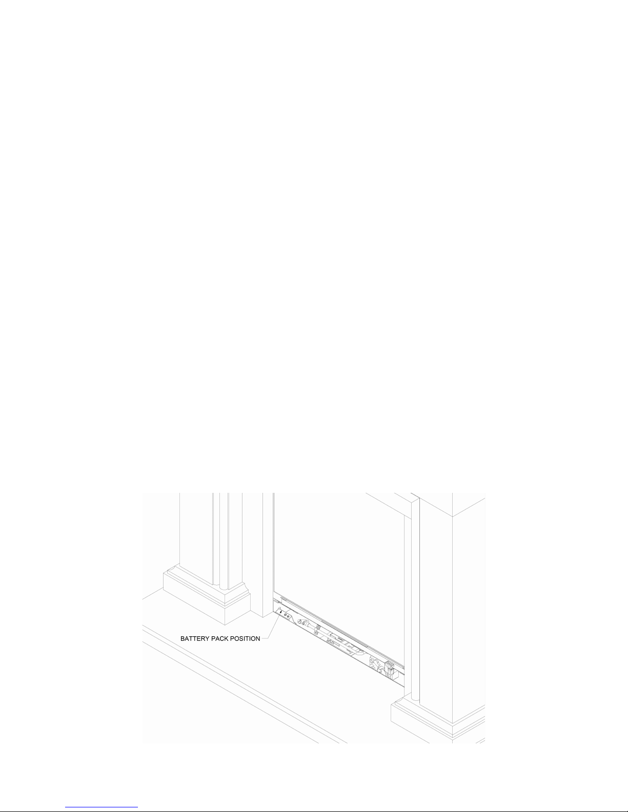
2.10.1 The product is supplied with a battery pack that is positioned at the front
left hand side of the fire as shown below in figure 12
2.10.2 Locate the battery pack by lifting away the lower infill, remove the screw
that holds the cover onto it and fit the 4 off AA sized batteries supplied
in the loose items pack.
Fig. 12
16
Page 18
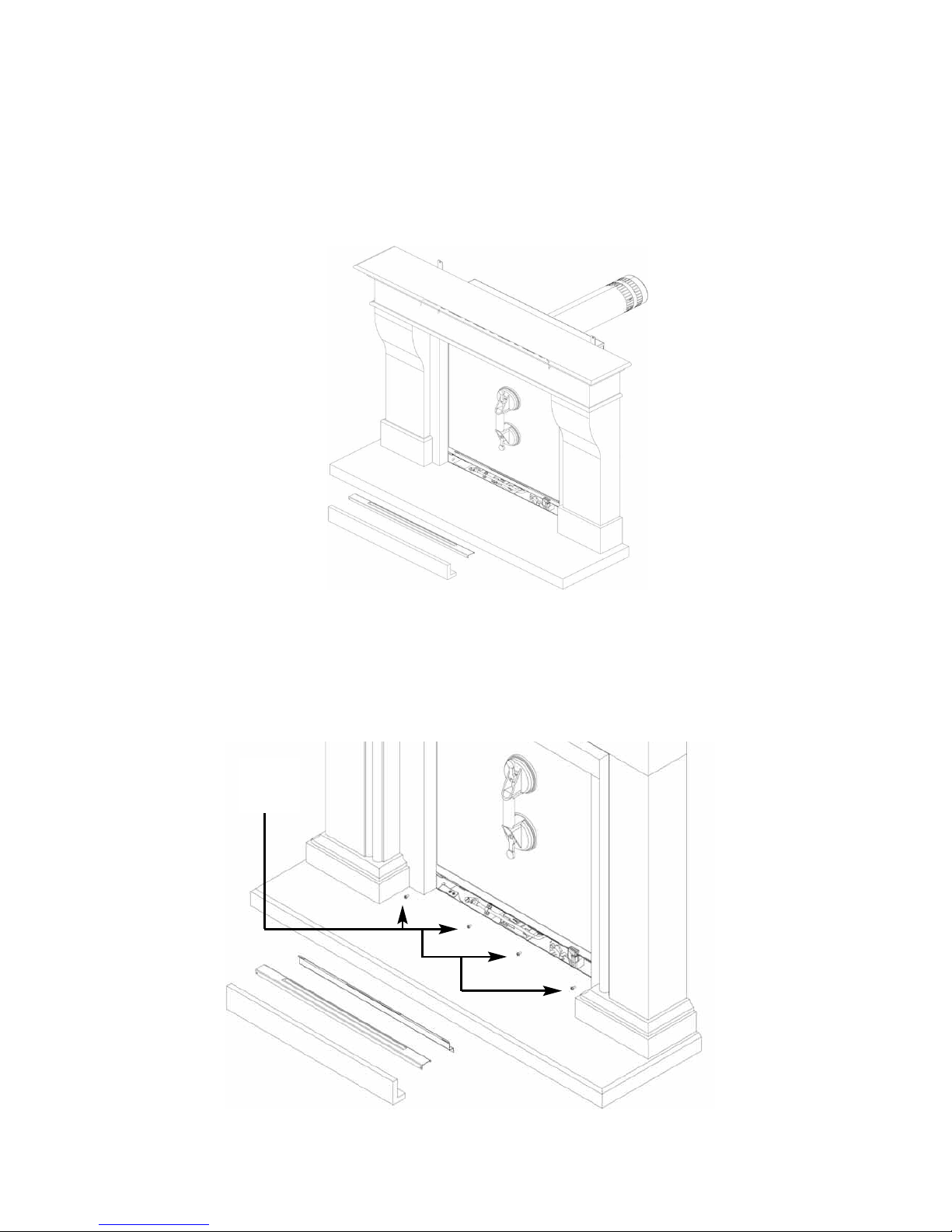
2.11 REMOVING & REFITTING OF THE GLASS FRAME.
2.11.1 Remove the glass panel by firstly removing the lower infill panel, and
black trim, then affixing the glass clamp to the glass panel as shown
below in figure 13 (Images shown with surround installed, please install
firebox before surround).
Fig. 13
2.11.2 Remove 5 off screws which hold the lower retaining bracket in
position. Remove the 4 off glass frame retaining screws as shown in
figure 14 below. (Images shown with surround installed, please install
firebox before surround).
Fig. 14
17
Glass
retaining
screws
Page 19
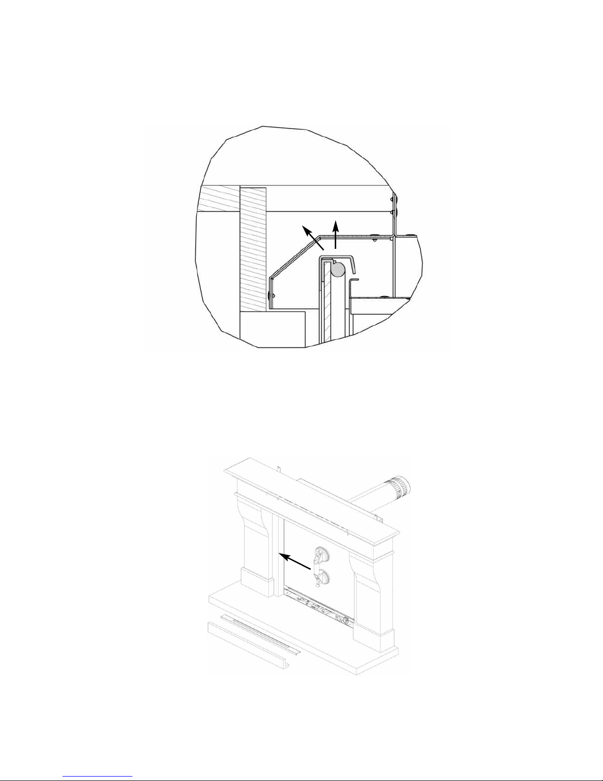
2.11.3 Unhook the glass panel from the top retaining channel by lifting
upwards then tilt the top edge of the glass assembly towards you as
shown below in figure 15 (sectional view shown through product for
clarity).
Fig. 15
2.11.4 Remove the glass frame assembly by dropping down, sliding to the left
until the right hand edge of the glass frame can be released from
behind the right hand leg of the surround as shown below in figure 16
and overpage in figure 17 (Images shown with surround installed,
please install firebox before surround).
Fig. 16
18
Page 20
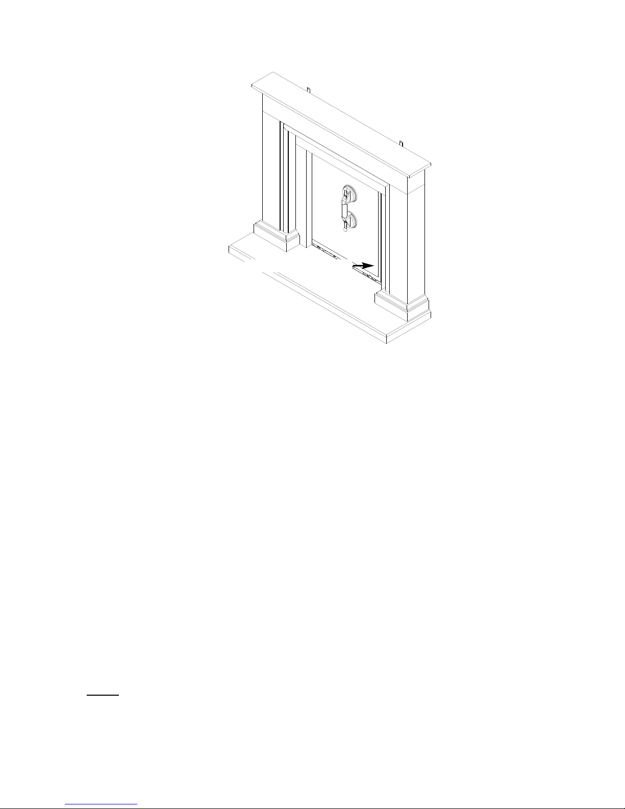
Fig. 17
2.11.5 Store the glass frame assembly in a safe place.
2.11.6 Re-assemble in reverse order when re-fitting the glass assembly.
Ensure that the glass assembly is correctly located on the top
flange of the combustion chamber, this can be achieved by putting
your hand onto the top edge of the glass frame inside the
convection air aperture and pushing down firmly to check the
glass frame is correctly located.
DO NOT OPERATE THE FIRE WITHOUT THE GLASS FRAME
ASSEMBLY IN POSITION OR NOT CORRECTLY LOCATED.
2.12 FITTING THE TERMINAL GUARD
2.12.1 With the flue terminal in position, place the terminal guard over the top
of the flue terminal and mark the position of the holes on the outer wall.
2.12.2 Remove the terminal guard and drill the 4 off 6 mm holes.
2.12.3 Insert the raw plugs into the drilled holes, replace the terminal guard
over the top of the flue terminal and attach to the wall using the No.12 x
40mm screws provided with the terminal guard.
NOTE : In England & Wales, building regulations require that a terminal guard should be
fitted if the terminal could come into contact with people near the building or be
subject to damage. BFM Europe Ltd. also recommend the fitting of a flue terminal
guard where regulations do not demand that it be fitted. A suitable flue terminal
guard is supplied with the appliance.
R/H edge of glass frame
19
Page 21
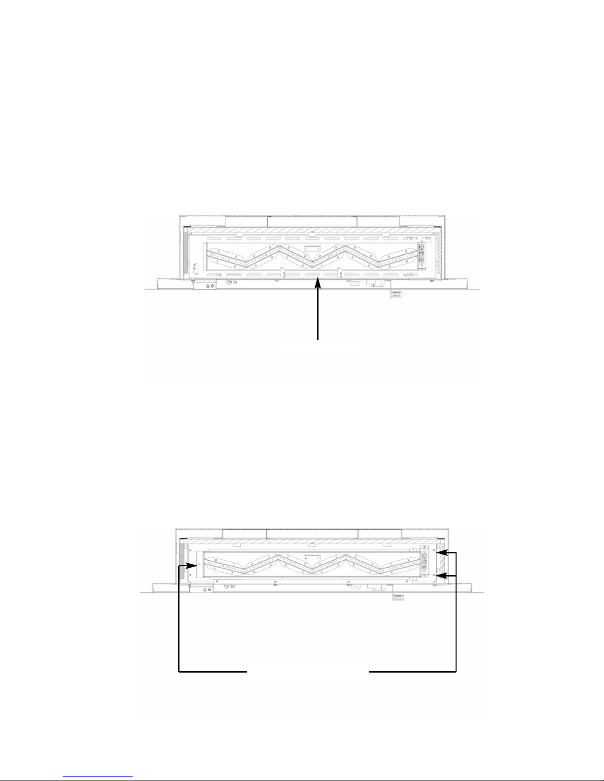
2.13 REMOVAL OF THE BURNER ASSEMBLY
2.13.1 Remove the burner. To allow burner removal, firstly remove the glass
frame assembly as per section 2.12. The fuel-bed support must be
removed to allow access to the burner fixings. Remove the fuel-bed
support as shown below in figure 18.
Fig. 18
2.13.2 Remove the 3 off screws that hold the burner in position, see figure 19
below.
Fig. 19
20
Fuel-bed Support
Viewed from Top
Viewed from Top
Three off burner retaining
screws
Page 22
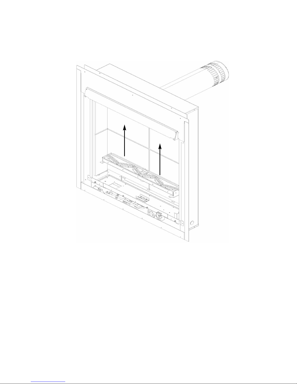
2.13.3 Remove the burner by lifting clear from the combustion chamber as
shown below in figure 20.
Fig. 20
2.13.4 Store the burner unit in a safe position.
2.13.5 Re-assemble in reverse order.
21
Page 23
SECTION 3
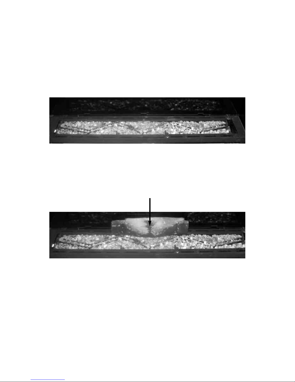
3.1 ASSEMBLING THE LOG FUEL-BED
3.1.1 Lay an even layer of vermiculite material across the burner tray as
shown below in figure 21.
Fig. 21
3.1.2 Place log “A” in a central position as shown below in figure 22, using
the location hole on the base of the log to position in line with the
location peg on the burner.
Fig. 22
22
Log A
Page 24
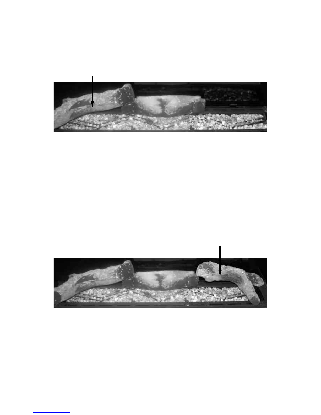
3.1.3 Place log “B” in position at the left hand side of the burner as shown
below in figure 23, using the cut out on the left hand side of log “A” as a
guide for placement and the locating lug at the LHS of the fuel tray.
Fig. 23
3.1.4 Place log “C” in position at the right hand side of the burner as shown
below in figure 24, using the cut-out on the right hand side of log “A” as
guide for placement.
Fig. 24
23
L
og B
Log C
Page 25
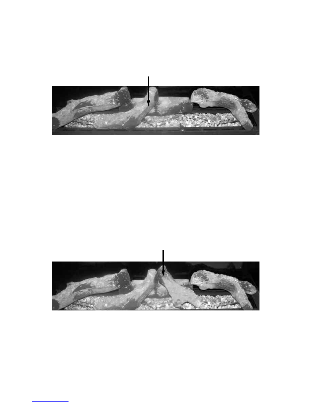
3.1.5 Place log “D” in position at the centre left hand side of the burner as
shown below in figure 25, using the locating peg at the front of the
burner and positioning on log “A” as shown.
Fig. 25
3.1.6 Place log “E” in position at the centre right hand side of the burner as
shown below in figure 26, using the locating peg at the front of the
burner and positioning on log “A” as shown.
Fig. 26
24
L
og D
Log E
Page 26
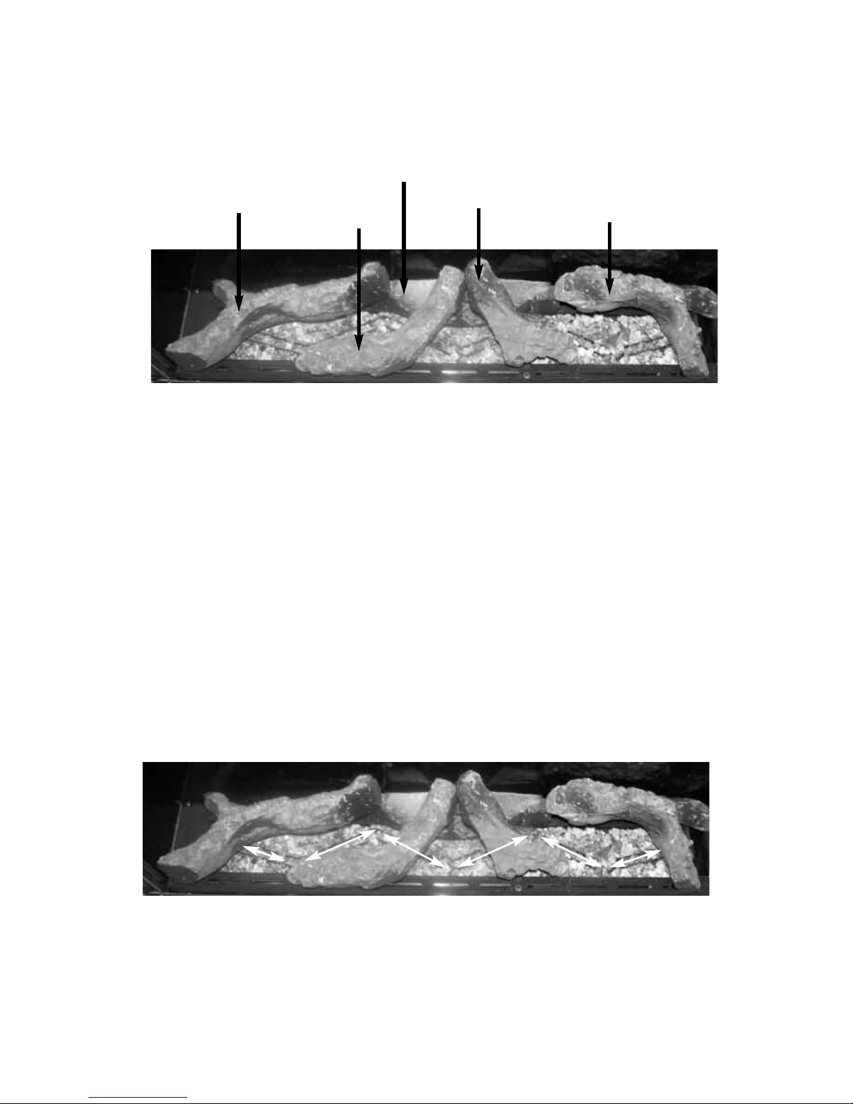
3.1.7 As a final check ensure that the logs are layed correctly as shown
below in figure 27.
Fig. 27
3.1.8 If required fit the embaglow material over the flame ports. To do this
seperate into short strands and place randomly over the flame porting
area as indicated by the arrows below in figure 28. This material is
only supplied to improve flame aesthetics and is optional to install.
Fig. 28
25
L
og D
Log E
L
og B
Log C
L
og A
Page 27

3.1.9 Re-fit the glass frame assembly as shown in section 2.11 before
proceeding to section 3.2
Warning : Use only the log fuel-bed supplied with the fire. When replacing
the log fuel-bed remove the old log fuel-bed and discard it. Fit a complete
log fuel-bed from the manufacturer, only use genuine replacements.
THE FOLLOWING STATEMENT IS APPLICABLE TO ALL FUEL-BED TYPES
This appliance uses fuel effect pieces containing Refractory Ceramic Fibres
(R.C.F.), which are man-made vitreous silicate fibres. Excessive exposure to
these materials may cause temporary irritation to eyes, skin and respiratory
tract. Consequently, it makes sense to take care when handling these
articles to ensure that the release of dust is kept to a minimum. To ensure
that the release of fibres from these R.C.F. articles is kept to a minimum,
during installation & servicing we recommend that you use a HEPA filtered
vacuum to remove any dust and soot accumulated in and around the fire,
before and after working on the fire. When replacing these articles we
recommend that the replaced items are not broken up, but are sealed within
a heavy duty polythene bag, clearly labelled as “RCF waste”. This is not
classified as “hazardous waste” and may be disposed of at a tipping site
licensed for the disposal of industrial waste. Protective clothing is not
required when handling these arrticles, but we do recommend you follow the
normal hygiene rules of not smoking, eating or drinking in the work area,
and always wash your hands before eating or drinking.
This appliance does not contain any component manufactured from
asbestos or asbestos related products.
26
Page 28
3.2 LIGHTING THE APPLIANCE
I
MPORTANT: IF THE BURNER IS EXTINGUISHED FOR ANY REASON YOU MUST ENSURE THAT
YOU WAIT A FULL FIVE MINUTES BEFORE ATTEMPTING TO RE-LIGHT THE FIRE.
The product is controlled by the remote handset supplied with the fire. Ensure the
1 off 9V battery as supplied in the loose items pack have been fitted to the remote
handset before attempting to use the handset and the batteries have been made
to the product as per section 2.10.
There are 4 modes of operation of the product, “MANUAL mode”,
“TEMPERATURE mode”, “TIMER mode”and “LIGHTING / DIMMER” mode.
3.2.1 Operation of the Fire in “MANUAL” mode
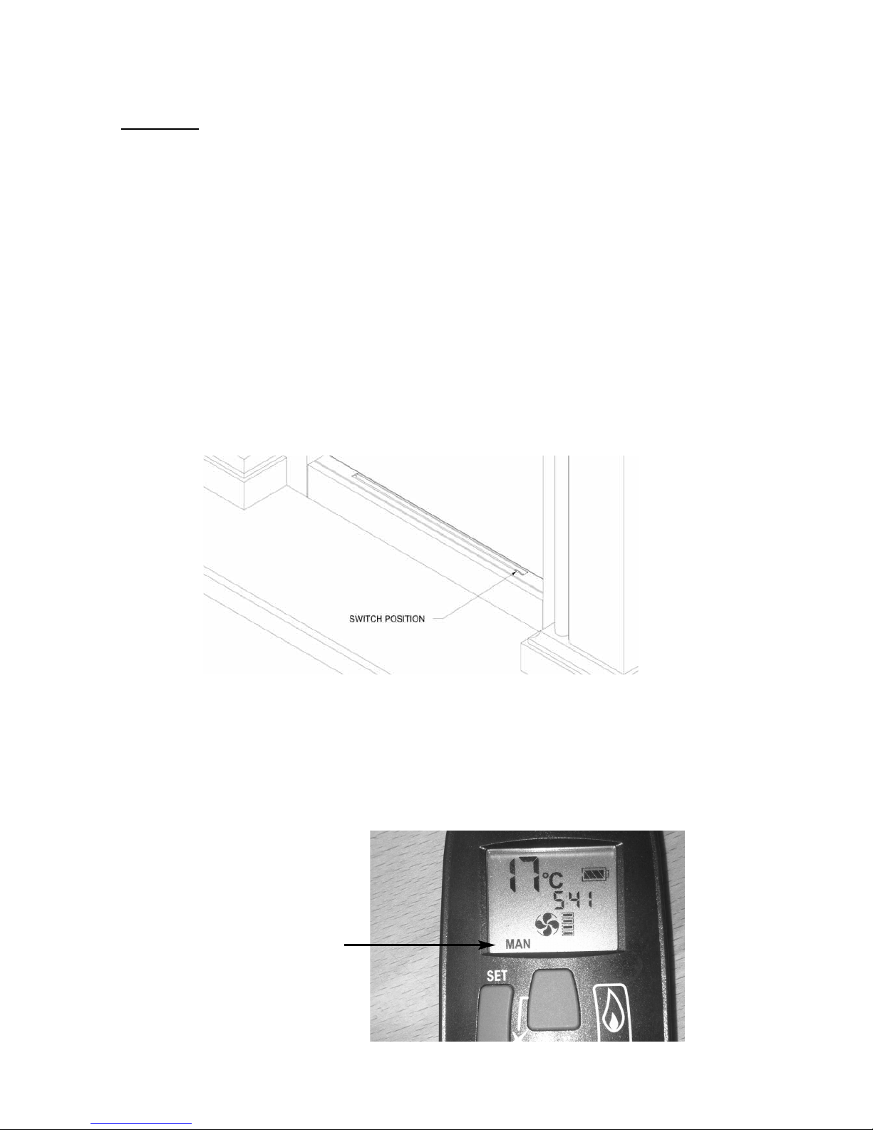
3.2.1.1 Locate the ON/OFF switch on the appliance, it is situated behind the
access cover at the bottom of the as shown below in figure 29. Ensure
that the on / off switch on the valve is in the “ON” (1) position
Fig. 29
3.2.1.2 The remote handset is now used to control all functions of the fire. To
light the fire, press the “UP” arrow and and “OFF” button simultateously.
as shown on figure 30 below. You will hear a click and the fire begins a
30 second ignition process. The pilot and main burner will light.
The appliance is now in “MANUAL mode” which will be shown via the
“MAN” graphic on the display of the handset as shown below in figure
30.
Fig. 30
27
Manual Graphic
on Handset Display
Page 29
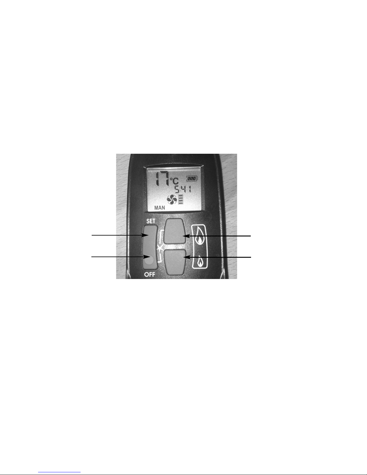
3.2.1.3 With the product in “MANUAL” mode the fire can now be switched
between HIGH rate heat input and LOW rate heat input by pressing the
“DOWN” arrow on the handset. To reduce the flame height of the main
burner incrementally, press the arrow momentarily. To reduce the heat
input directly down to the minimum level, press the “SMALL” flame
arrow on the handset twice, “LO” will be displayed. NOTE : The flame
will go to HIGH rate heat input before going to designated LOW rate
heat input. To return back to HIGH rate heat input press the
“LARGE” flame button twice. To put the fire in In “STANDBY MODE”
(only the pilot remains lit) press and hold the “SMALL” flame arrow on
the handset. See figure 31 below.
Fig. 31
3.2.1.4 To turn the fire off, press the “OFF” button, this will extinguish all flames
including the pilot.
28
“SET” Button
“OFF” Button
“LARGE” Flame /
“UP” Arrow Button
“SMALL” Flame /
“DOWN” Arrow Button
Page 30
3.2.2 Operation of the Fire in “TEMPERATURE” mode
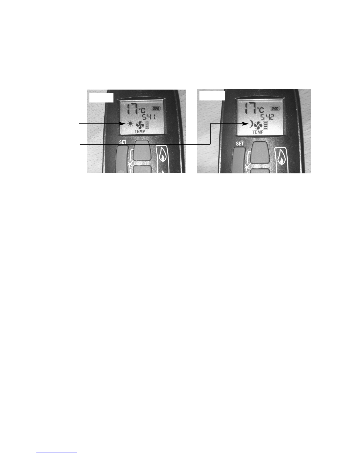
3.2.2.1 In order to change the mode of operation from “MANUAL” to
“TEMPERATURE”, press the “SET” button, the fire will then change
to either “DAY TEMP” (figure 32) mode or “NIGHT TEMP” mode (figure
33). To alternate between the 2, press the “SET” button. The display
on the handset will show the current temperature in the room.
NOTE : The “SET” button allows you to alternate between all modes of
operation :- “ MANUAL”, “DAY TEMP”, “NIGHT TEMP”, “TIMER” and
back to “MANUAL”. Alternatively, pressing either the “UP” or “DOWN”
arrow allows the unit to revert to “MANUAL” mode. Fire must be in
standby mode (pilot must be lit) for temperature mode to be used.
3.2.2.2 Within the “TEMPERATURE” mode there are options for either “DAY
TEMP” or “NIGHT TEMP”. These temperatures can be set
independently to allow a higher temperature to be maintained at night
than during the day, or if setting the same temperature for day and night
the fire will compensate for the generally cooler evening temperatures
and automatically increase the heat input level accordingly.
3.2.2.3 To set the temperature, ensure the handset is in “TEMPERATURE”
mode and then press the “SET” button until the “TEMP” display flashes
then let go. Proceed to set the desired temperature by pressing the
“UP” (large flame) or “DOWN” (small flame) arrows as necessary, then
press “OFF” to complete the process.
NOTE : Minimum temperature is 5oC, Maximum temperature is 30oC,
or minimum 41F to maximum 86F when in Fahrenheit mode.
3.2.2.4 Press the “OFF” button to stop the display flashing or wait to return to
“TEMPERATURE” mode. NOTE : If you set a temperature below the
current room temperature the fire will switch to standby mode (pilot
burner only) until the room has cooled to the temperature you have set
on the handset display.
3.2.2.5 If you would like the “NIGHT TEMP” to turn the fire off then decrease
the temperature until [----] is displayed.
29
“DAY TEMP”
Mode
“NIGHT TEMP”
Mode
Fig. 32
Fig. 33
Page 31
3.2.3 Operation of the Fire in “TIMER” mode
3.2.3.1 In order to change the mode of operation from “MANUAL” to
“TIMER”, press the “SET” button, the fire will then alternate
between the settings until the “TIMER” mode is displayed.
NOTE : The “SET” button allows you to alternate between all modes of
operation :- “ MANUAL”, “DAY TEMP”, “NIGHT TEMP”, “TIMER” and
back to “MANUAL”. Alternatively, pressing either the “UP” or “DOWN”
arrow allows the unit to revert to “MANUAL” mode. Fire must be in
standby mode (pilot must be lit) for temperature mode to be used.
3.2.3.2 Within the “TIMER” setting mode there are two programmable settings
you can make over a 24 hour period, namely P1 and P2. To set the
timer, ensure the handset is in “TIMER” mode as detailed in section
3.2.3.1 above.
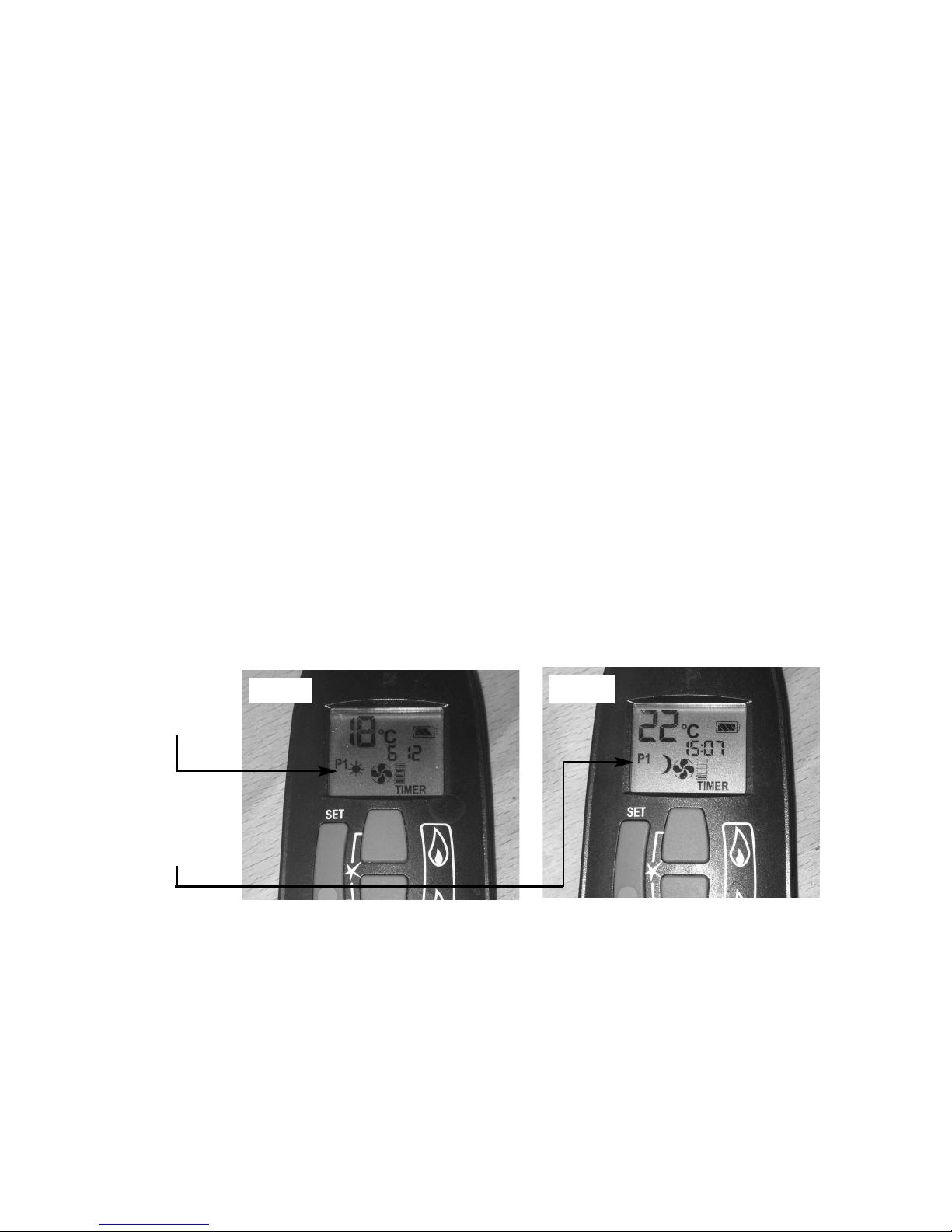
3.2.3.3 To set the P1 timed start setting, press and hold the “SET” button until
the P1 (sun symbol is displayed as per figure 34 below) and the time
flashes. Set the hour by pressing the “UP” (large flame) and set the
minutes (in ten minute increments) by pressing the “DOWN” (small
flame) as necessary, then press “OFF” button to complete the process.
Repeat for the P1 (moon symbol is displayed as per figure 35 below)
Set the hour by pressing the “UP” (large flame) and set the minutes (in
ten minute increments) by pressing the “DOWN” (small flame) as
necessary, then press “OFF” button to complete the process.
3.2.3.4 To set the P2 timed setting, press the “SET” button until the “TIMER”
mode is displayed. Hold the “SET” button until the display flashes the
current time for P1. Press the “SET” button again to scroll past the
setting for P1 (sun) and P1 (moon). The time should now be flashing
on the handset. Set the hour by pressing the “UP” (large flame) and set
the minutes (in ten minute increments) by pressing the “DOWN” (small
flame) as necessary, then press “OFF” button to complete the process.
30
Fig. 34
Fig. 35
P1 with “Sun”
symbol
illuminated
P1 with
“Moon”
symbol
illuminated
Page 32

3.2.5 Low Battery Signal
3.2.5.1 When the battery in the handset needs replacing, “BATT” will be
displayed on the handset.
3.2.5.2 Remove the cover on the rear of the handset and replace the 3 off AAA
batteries as necessary.
3.2.6 To Set the Time on the Remote Handset
3.2.6.1 Simultanelously press the “UP” (large flame) arrow and “DOWN” (small
flame) arrow buttons on the remote handset.
3.2.6.2 Press the “UP” (large flame) arrow to set the hour and the “DOWN”
(small flame) arrow to set the minutes.
3.2.7 To Set the oC / 24 Hour or oF / 12 Hour Clock
3.2.7.1 Press and hold the “OFF” and the “DOWN” (small flame) arrow buttons
on the handset simultaneously until the display changes from oC to oF
and vice versa
3.3 Fitting the handset wall bracket
3.3.1 The wall bracket is supplied in the loose items pack and is optional to
fit.
3.3.2 If fitting the wall bracket, please be advised that the thermostatic
sensor is contained within the handset itself, so the position of the
wall bracket will therefore be the position of temperature
measurement within the room. To fit, position as necessary, mark hole
positions, drill and secure with fixings provided.
3.4 Instructing the user / product handover
3.4.1 Instruct the user on the operation of the fire and the handset.
3.4.2 Hand the glass clamp over and advise the customer to store it in a safe
place.
31
Page 33

SECTION 4
MAINTENANCE
Servicing should be carried out annually by a competent person such as a
GAS SAFE registered engineer. It is a condition of the guarantee scheme
that this is carried out by a competent person i.e a GAS SAFE
registered Engineer in accordance with these servicing notes and that the
themocouple is changed annually as a condition of the guarantee.
The condition of the logs should be checked and if necessary the whole set
should be replaced with a genuine replacement set.
The burner assembly is designed to be removed as a complete unit for ease of
access. After any servicing work a gas tightness check must always be
carried out.
For Diagrams refer to Section 2
4.1 Removing the burner assembly from the fire.
4.1.1 Prepare work area (lay down dust sheets etc.)
4.1.2 Remove the glass assembly, remove the ceramic logs and vermiculite.
4.1.3 Unscrew and remove the three screws which retain the burner ,then
lift clear.
4.1.4 To refit the burner assembly, locate the burner unit and refit the three
screws. Refit the fuel-bed referring to section 3 for the correct log
positions. Re-fit the glass frame assembly.
4.2 Removing the gas control valve
4.2.1 Remove the burner assembly as detailed in section 4.1
4.2.2 Isolate the gas supply at the inlet elbow. Remove the controls mounting
plate which is held in position by nine screws. Lift the controls mounting
plate clear taking care not to damage the wiring to the receiver unit.
4.2.3 Remove the valve retaining screws and pipework and remove the valve.
Re-assemble in reverse order and carry out a gas tightness test.
32
Page 34

4.3 Removing the pilot assembly.
N
ote : Because this appliance is fitted with an atmosphere sensing ‘Oxy-Pilot’ it is not possible to
replace the thermocouple separately, because the thermocouple position is factory set to a tight
tolerance. Any replacement of parts on the pilot requires a complete new pilot assembly.
4.3.1 Prepare work area (lay down dust sheets etc.)
4.3.2 Remove the glass frame assembly as shown in section 2.2 and put it in
a safe location. Remove burner assembly as per section 4.1
4.3.3 Loosen the pilot nut and remove the two screws retaining the pilot
assembly. Unscrew the thermocouple from the gas valve.
4.3.4 Re-assemble in reverse order and carry out a gas tightness test.
4.4 Replacing the batteries in the handset.
4.4.1 Remove and re-fit the new 1 off 9V PP3 battery by removing the cover
on the back of the handset.
4.5 Replacing the batteries in the fire.
4.5.1 Remove the bottom surround infill.
4.5.2 Locate the battery pack at the bottom L/H/S, lift clear and remove the
rear cover from the battery pack by unscrewing the retaining screw.
4.5.3 Replace batteries and re-assemble in reverse order.
4.6 Removing the control board.
4.6.1 Remove the burner from the combustion chamber as described in
section 4.1 and the controls mounting plate as described in section 4.2
4.6.2 Disconnect the interrupter wires, & wiring loom and then lift the control
board clear. Replace in reverse order and re-code handset to the new
receiver.
33
Page 35

4.7 PARTS SHORTLIST
Replacement of any other parts must be carried out by a competent person such
as a GAS SAFE registered gas installer. The part numbers of the main
replaceable parts are as follows, these are available from your local Flavel
stockist, whose details can be found on the BFM Europe website, in the “stockist”
section.
GV60 Gas control valve B-92200
GV60 Receiver unit B-153140
GV60 Remote control thermostatic handset B-159270
GV60 8 wire cable B-153720
GV60 On/off switch with cables CV-104931
Thermocouple Interupter B-93300
Cable Interupter B-93310
Battery pack B-110160
Ignition lead B-128640
Glass frame assembly 1177-179340
Complete log set B-182450
Log “A” only B-184680
Log “B” only B-184690
Log “C” only B-184700
Log “D” only B-184710
Log “E” only B-184720
Emba-glow material B-120070
Bag of vermiculite CV-107116
Pilot assy CV-104530
34
Page 36

SECTION FIVE - USER INSTRUCTIONS
5.1 Installation Information
Conditions of Installation
It is the law that all gas appliances are installed only by a competent (e.g. GAS
SAFE) Registered Installer, in accordance with the installation instructions and the
Gas Safety (Installation and Use) Regulations 1998. Failure to install appliances
correctly could lead to prosecution. It is in your own interest and that of safety to
comply with the law.
The fire may be fitted below a combustible shelf provided that the shelf is at least
200mm above the top of the appliance and the depth of the shelf does not exceed
150mm.
The fire must not be installed below combustible shelves.
No purpose made additional ventilation is normally required for this
appliance when installed in G.B. When installed I.E. please consult
document I.S. 813 : 1996 Domestic Gas Installation which is issued by the
National Standards Authority of Ireland. Any purpose made ventilation
should be checked periodically to ensure that it is free from obstruction.
If the chimney or flue has been previously used by appliances burning fuels other
than gas they must be swept prior to the installation of this fire.
If this appliance and surround is fitted directly on to a wall soft wall coverings such
as wallpaper, blown vinyl etc. could be affected by the heat and hot air and may
discolour or scorch. This should be considered when installing or decorating.
The Model number of this appliance is as stated on the rating plate affixed to the
control panel of the fire and the appliance is manufactured by:-
BFM Europe Ltd.
Trentham Lakes
Stoke on Trent
ST4 4TJ
35
Page 37

5.2 ABOUT YOUR NEW SOPHIA GAS FIRE
The Flavel Sophia log effect gas fires incorporate a unique and highly developed
fuel bed which gives the realism of a loose log layout combined with realistic
flames and glow. The use of durable ceramic material in the construction of the
fuelbed components ensures long and trouble free operation.
Please take the time to fully read these instructions as you will then be able to
obtain the most effective and safe operation of your fire.
IMPORTANT SAFETY INFORMATION
WARNING
This appliance is a heating appliance and as with all heating appliances a
fireguard should be used for the protection of children, the elderly and
infirm. Fireguards should conform to B.S. 8423 : 2002 (Fireguards for use
with gas heating appliances). It is important that this appliance is serviced at
least once a year by a GAS SAFE registered engineer. During the annual service,
replacement of the pilot must be carried out. This is a condition of the
manufacturers guarantee. Any debris or deposits should be removed from the
fuel bed from time to time. This may be carried out by referring to the cleaning
section as described later in this book. Only the correct number and type of logs
must be used and only complete and genuine replacement sets must be used.
Always keep furniture and combustible materials well clear of the fire and never
dry clothing or items either on or near to the fire. Never use aerosols or flammable cleaning products near to the fire when it is in use. The ceramic fuel bed
remains hot for a considerable period after use and sufficient time should be
allowed for the fire to cool before cleaning etc.
IMPORTANT NOTE :
DO NOT UNDER ANY CIRCUMSTANCES USE THIS FIRE IF THE GLASS PANEL IS
BROKEN, CRACKED OR MISSING.
36
Page 38
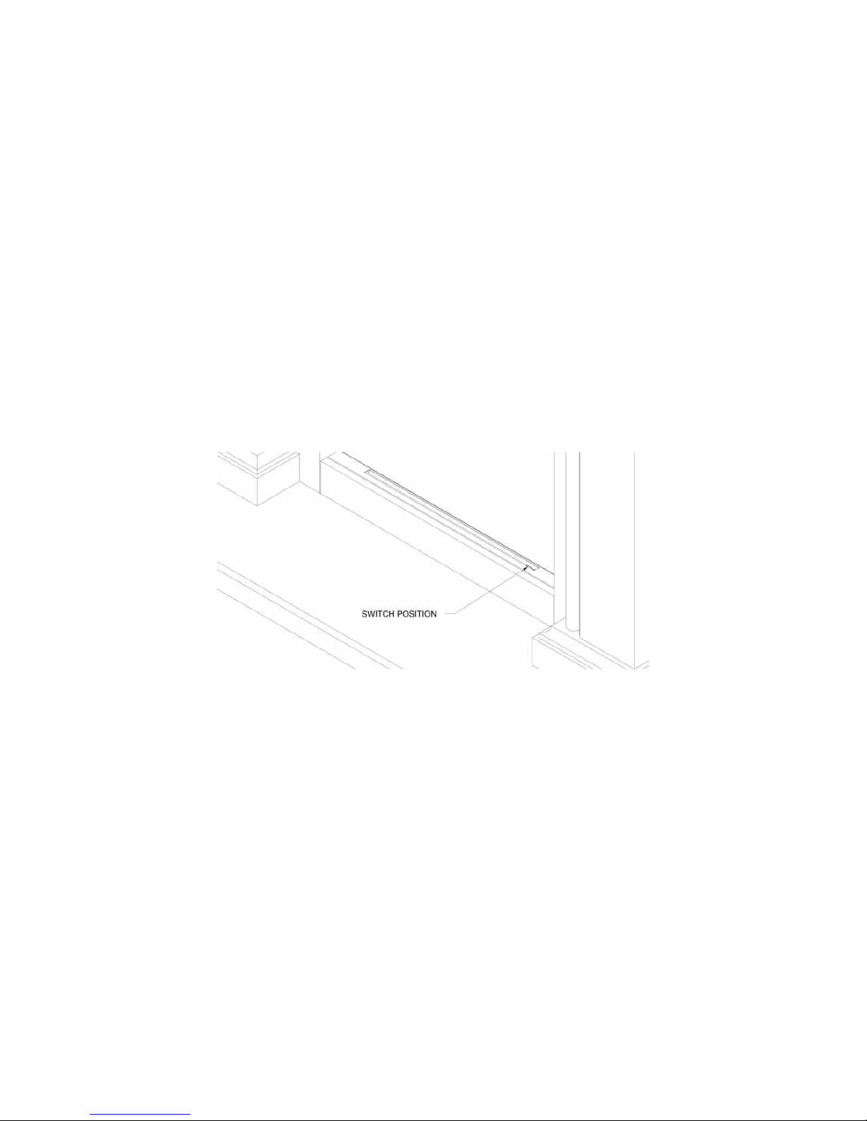
5.3 LIGHTING THE FIRE / USER CONTROLS
IMPORTANT : IF THE BURNER IS EXTINGUISHED FOR ANY REASON YOU
MUST ENSURE THAT YOU WAIT A FULL THREE MINUTES
BEFORE ATTEMPTING TO RE-LIGHT THE FIRE.
The product is controlled by the remote handset supplied with the fire. Ensure the
1 off 9V PP3 battery as supplied in the loose items pack has been fitted to the
remote handset before attempting to use the handset. There are 4 modes of
operation of the product, “MANUAL mode”, “TEMPERATURE mode”, “TIMER
mode” and “LIGHTING / DIMMER” mode.
5.3.1 Operation of the Fire in “MANUAL” mode
5.3.1.1 Locate the ON/OFF switch on the appliance, it is situated as shown
below in figure 1. Ensure that the on / off switch is in the “ON” (1)
position.
Fig. 1
5.3.1.2 The remote handset is now used to control all functions of the fire. To
light the fire, press the “UP” arrow and and “OFF” button simultateously
as shown on figure 2 overpage. You will hear a click and the fire begins
a 30 second ignition process. The pilot and main burner will light. The
appliance is now in “MANUAL mode” which will be shown via the “MAN”
graphic on the display of the handset as shown overpage in figure 2.
37
Page 39
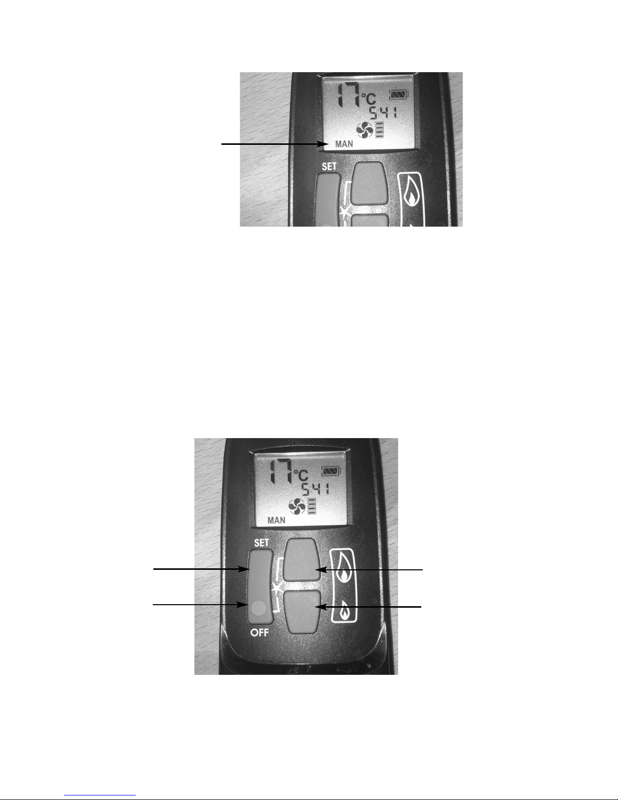
Fig. 2
5.3.1.3 With the product in “MANUAL” mode the fire can now be switched
between HIGH rate heat input and LOW rate heat input by pressing the
“DOWN” arrow on the handset. To reduce the flame height of the main
burner incrementally, press the arrow momentarily. To reduce the heat
input directly down to the minimum level, press the “SMALL” flame
arrow on the handset twice, “LO” will be displayed. NOTE : The flame
will go to HIGH rate heat input before going to designated LOW rate
heat input. To return back to HIGH rate heat input press the
“LARGE” flame button twice. To put the fire in In “STANDBY MODE”
(only the pilot remains lit) press and hold the “SMALL” flame arrow on
the handset. See figure 3 below.
Fig. 3
5.3.1.4 To turn the fire off, press the “OFF” button, this will extinguish all flames
including the pilot.
38
Manual Graphic
on Handset Display
“SET” Button
“OFF” Button
“LARGE” Flame /
“UP” Arrow Button
“SMALL” Flame /
“DOWN” Arrow Button
Page 40
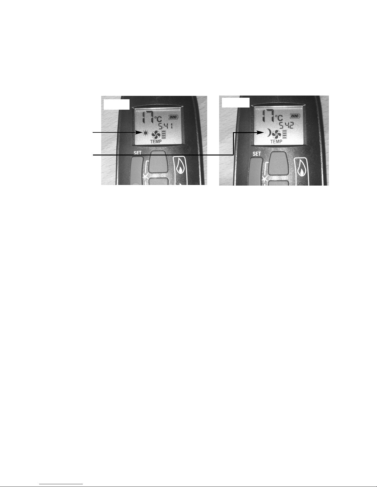
5.3.2 Operation of the Fire in “TEMPERATURE” mode
5.3.2.1 In order to change the mode of operation from “MANUAL” to
“TEMPERATURE”, press the “SET” button, the fire will then change to
either “DAY TEMP” (figure 4) mode or “NIGHT TEMP” mode (figure 5).
To alternate between the 2, press the “SET” button. The display on
the handset will show the current temperature in the room.
NOTE : The “SET” button allows you to alternate between all modes of
operation :- “ MANUAL”, “DAY TEMP”, “NIGHT TEMP”, “TIMER”,
“LIGHT / DIMMER” and “CIRCULATING FAN” then back to “MANUAL”.
Alternatively, pressing either the “UP” or “DOWN” arrow allows the unit
to revert to “MANUAL” mode. Fire must be in standby mode
(pilot must be lit) for temperature mode to be used.
5.3.2.2 Within the “TEMPERATURE” mode there are options for either “DAY
TEMP” or “NIGHT TEMP”. These temperatures can be set
independently to allow a higher temperature to be maintained at night
than during the day, or if setting the same temperature for day and night
the fire will compensate for the generally cooler evening temperatures
and automatically increase the heat input level accordingly.
5.3.2.3 To set the temperature, ensure the handset is in “TEMPERATURE”
mode and then press the “SET” button until the “TEMP” display flashes
then let go. Proceed to set the desired temperature by pressing the
“UP” (large flame) or “DOWN” (small flame) arrows as necessary, then
press “OFF” to complete the process.
NOTE : Minimum temperature is 5oC, Maximum temperature is 30oC,
or minimum 41F to maximum 86F when in Fahrenheit mode.
5.3.2.4 Press the “OFF” button to stop the display flashing or wait to return to
“TEMPERATURE” mode. NOTE : If you set a temperature below the
current room temperature the fire will switch to standby mode (pilot
burner only) until the room has cooled to the temperature you have set
on the handset display.
5.3.2.5 If you would like the “NIGHT TEMP” to turn the fire off then decrease
the temperature until [----] is displayed.
39
“DAY TEMP”
Mode
“NIGHT TEMP”
Mode
Fig. 4
Fig. 5
Page 41
5.3.3 Operation of the Fire in “TIMER” mode
5.3.3.1 In order to change the mode of operation from “MANUAL” to “TIMER”,
press the “SET” button, the fire will then
alternate between the settings until the “TIMER” mode is displayed.
NOTE : The “SET” button allows you to alternate between all modes of
operation :- “ MANUAL”, “DAY TEMP”, “NIGHT TEMP”, “TIMER” and
back to “MANUAL”. Alternatively, pressing either the “UP” or “DOWN”
arrow allows the unit to revert to “MANUAL” mode. Fire must be in
standby mode (pilot must be lit) for temperature mode to be used.
5.3.3.2 Within the “TIMER” setting mode there are two programmable settings
you can make over a 24 hour period, namely P1 and P2. To set the
timer, ensure the handset is in “TIMER” mode as detailed in section
5.3.3.1 above.
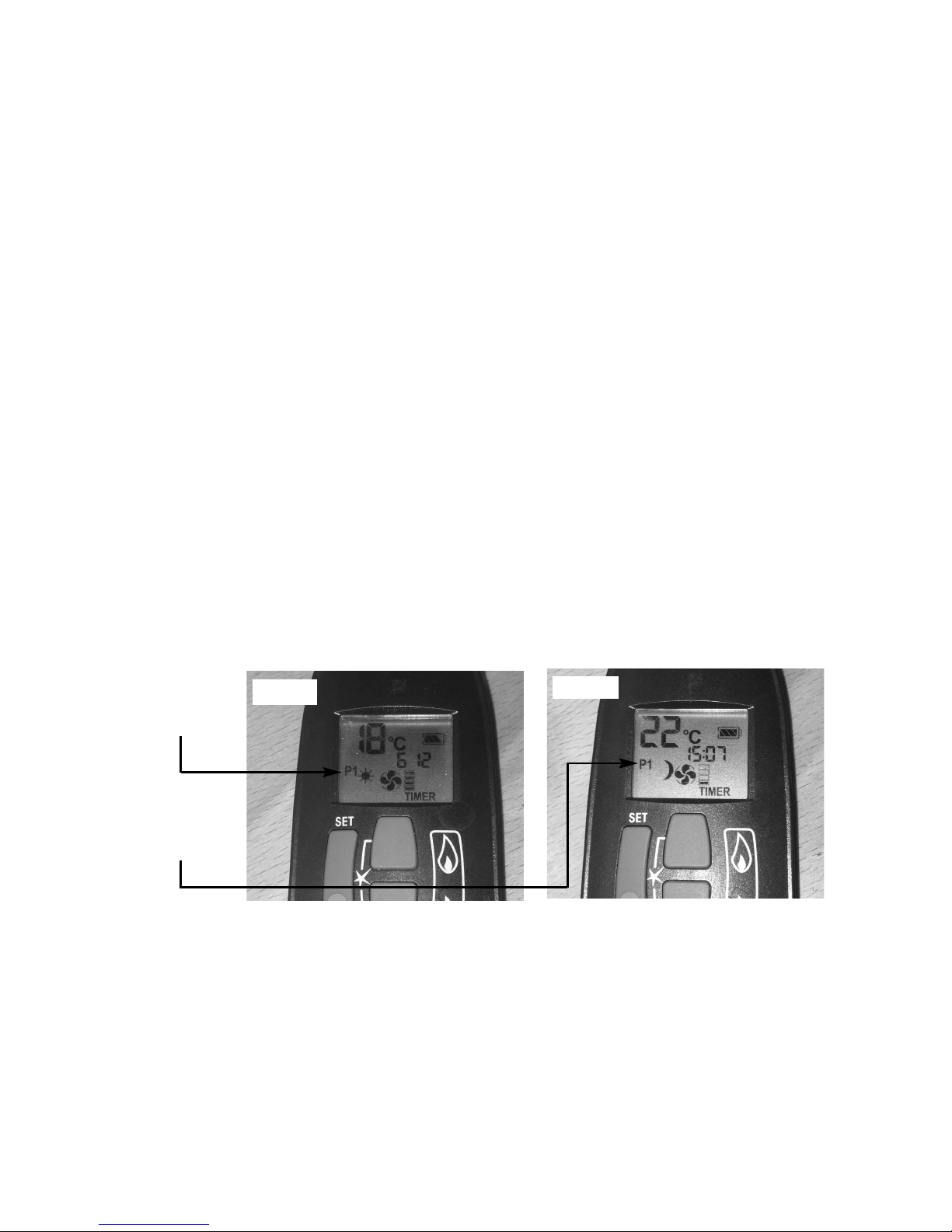
5.3.3.3 To set the P1 timed start setting, press and hold the “SET” button until
the P1 (sun symbol is displayed as per figure 6 below) and the time
flashes. Set the hour by pressing the “UP” (large flame) and set the
minutes (in ten minute increments) by pressing the “DOWN” (small
flame) as necessary, then press “OFF” button to complete the
process. Repeat for the P1 (moon symbol is displayed as per figure
below) Set the hour by pressing the “UP” (large flame) and set the
minutes (in ten minute increments) by pressing the “DOWN” (small
flame) as necessary, then press “OFF” button to complete the process.
Fig. 6
Fig. 7
P1 with “Sun”
symbol
illuminated
P1 with
“Moon”
symbol
illuminated
40
Page 42

5.3.4 Low Battery Signal
5.3.4.1 When the battery in the handset needs replacing, “BATT” will be
displayed on the handset.
5.3.4.2 Remove the cover on the rear of the handset and replace the 1 off 9V
battery as necessary.
41
Page 43
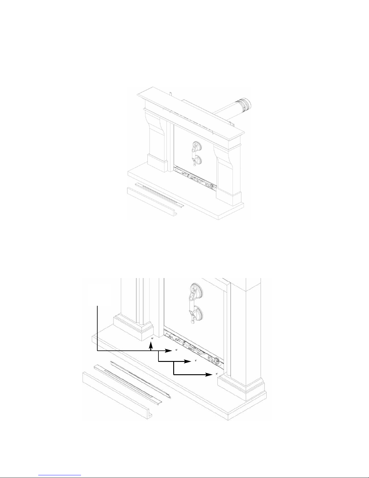
5.4 REMOVAL / RE-FITTING THE GLASS FRAME ASSEMBLY
5.4.1 Remove the glass panel by firstly affixing the glass clamp to the glass
panel as shown below in figure 8.
Fig. 8
5.4.2 Remove 5 off screws which hold the lower retaining bracket in
position. Remove the 4 off glass frame retaining screws as shown in
figure 14 below. (Images shown with surround installed, please install
firebox before surround).
Fig. 9
42
Glass
retaining
screws
Page 44
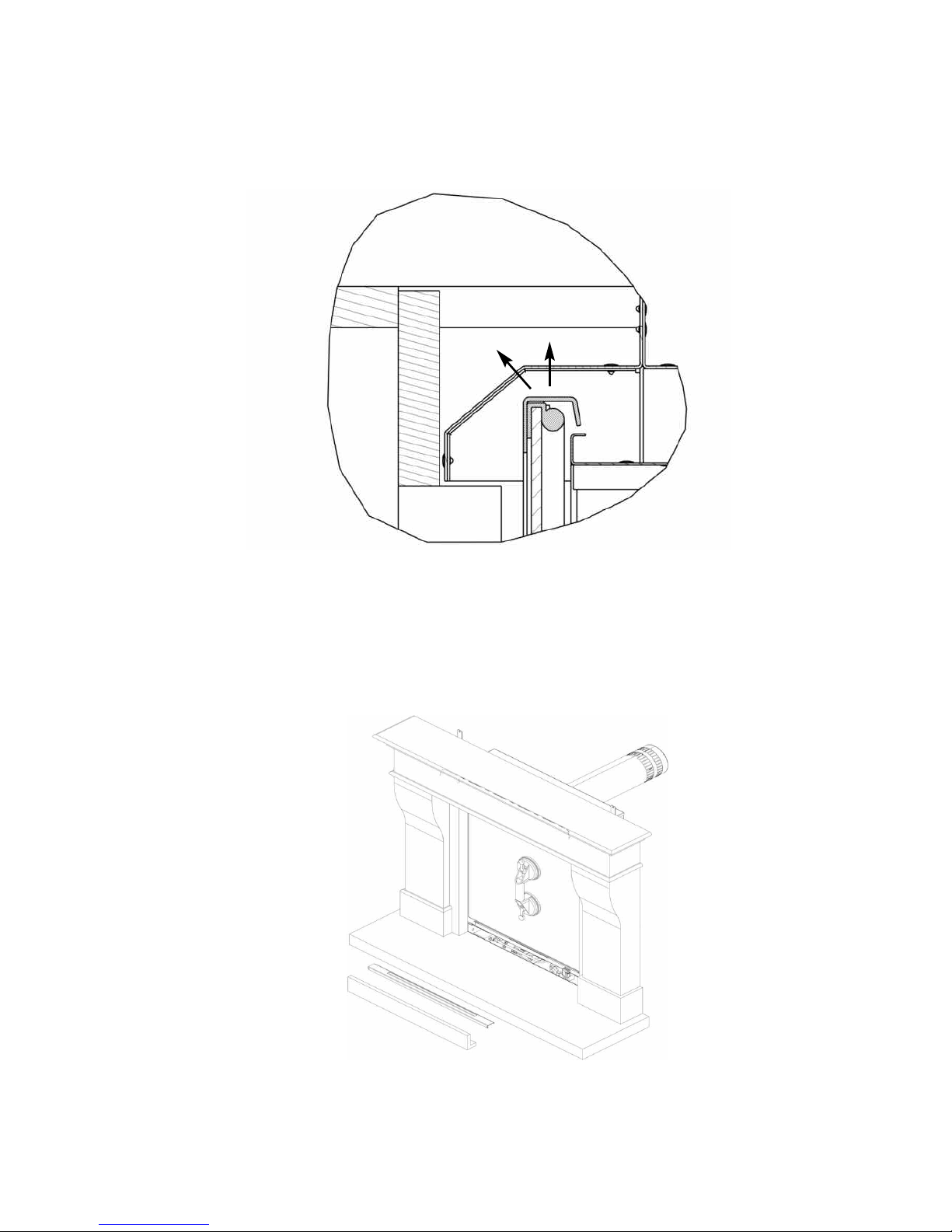
5.4.3 Unhook the glass panel from the top retaining channel by lifting
upwards then tilt the top edge of the glass assembly towards you as
shown below in figure 10 (sectional view through product for clarity).
Fig. 10
5.4.3 Remove the glass frame assembly by sliding to the left until the right
hand edge of the glass frame can be released from behind the right
hand leg of the surround as shown below in figure 11 and overpage
in figure 12.
Fig. 11
43
Page 45
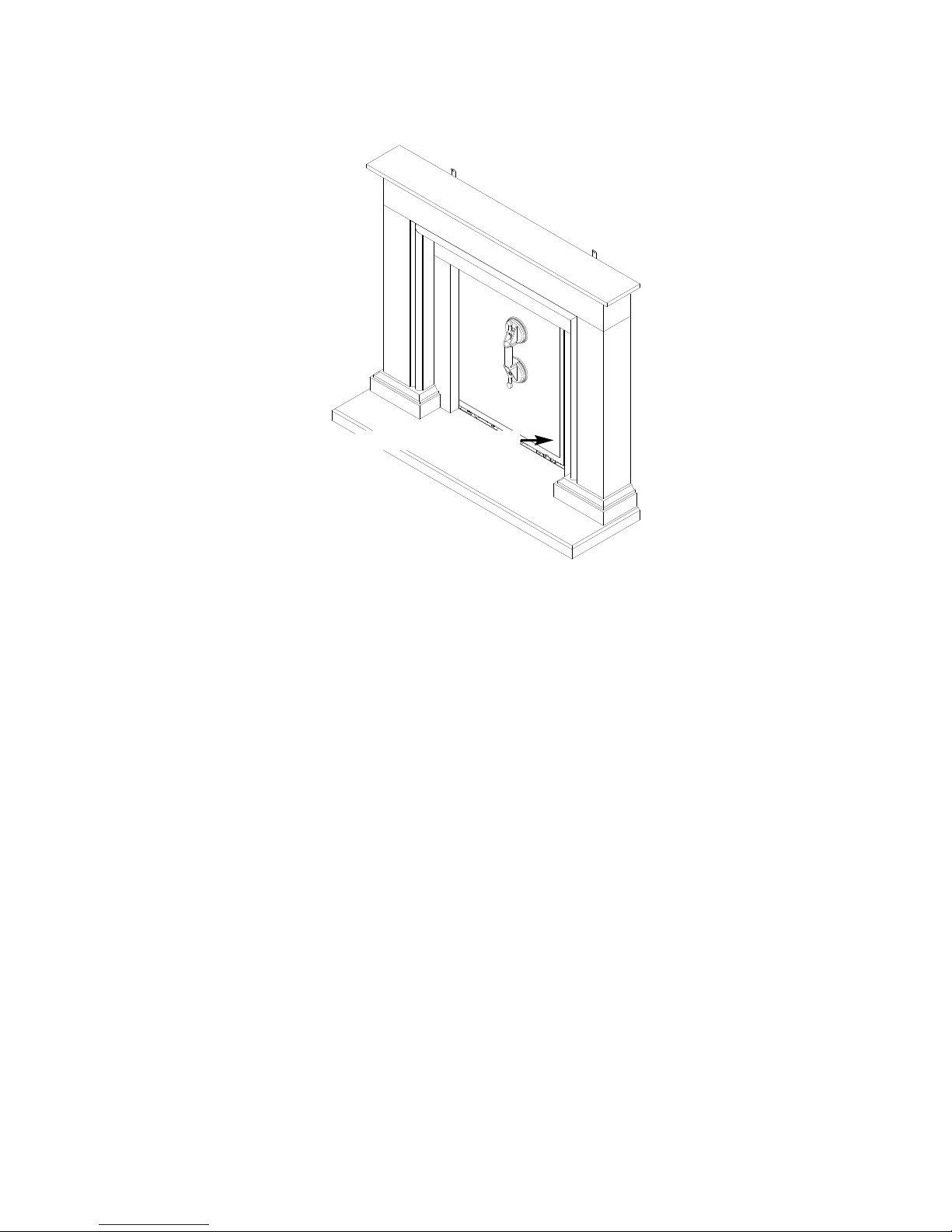
Fig. 12
5.4.4 Store the glass frame assembly in a safe place.
5.4.5 Re-assemble in reverse order when re-fitting the glass assembly.
Ensure that the glass assembly is correctly located on the top
flange of the combustion chamber, this can be achieved by putting
your hand onto the top edge of the glass frame inside the
convection air aperture and pushing down firmly to check the
glass frame is correctly located.
DO NOT OPERATE THE FIRE WITHOUT THE GLASS FRAME
ASSEMBLY IN POSITION OR NOT CORRECTLY LOCATED.
44
R/H edge of glass frame
Page 46
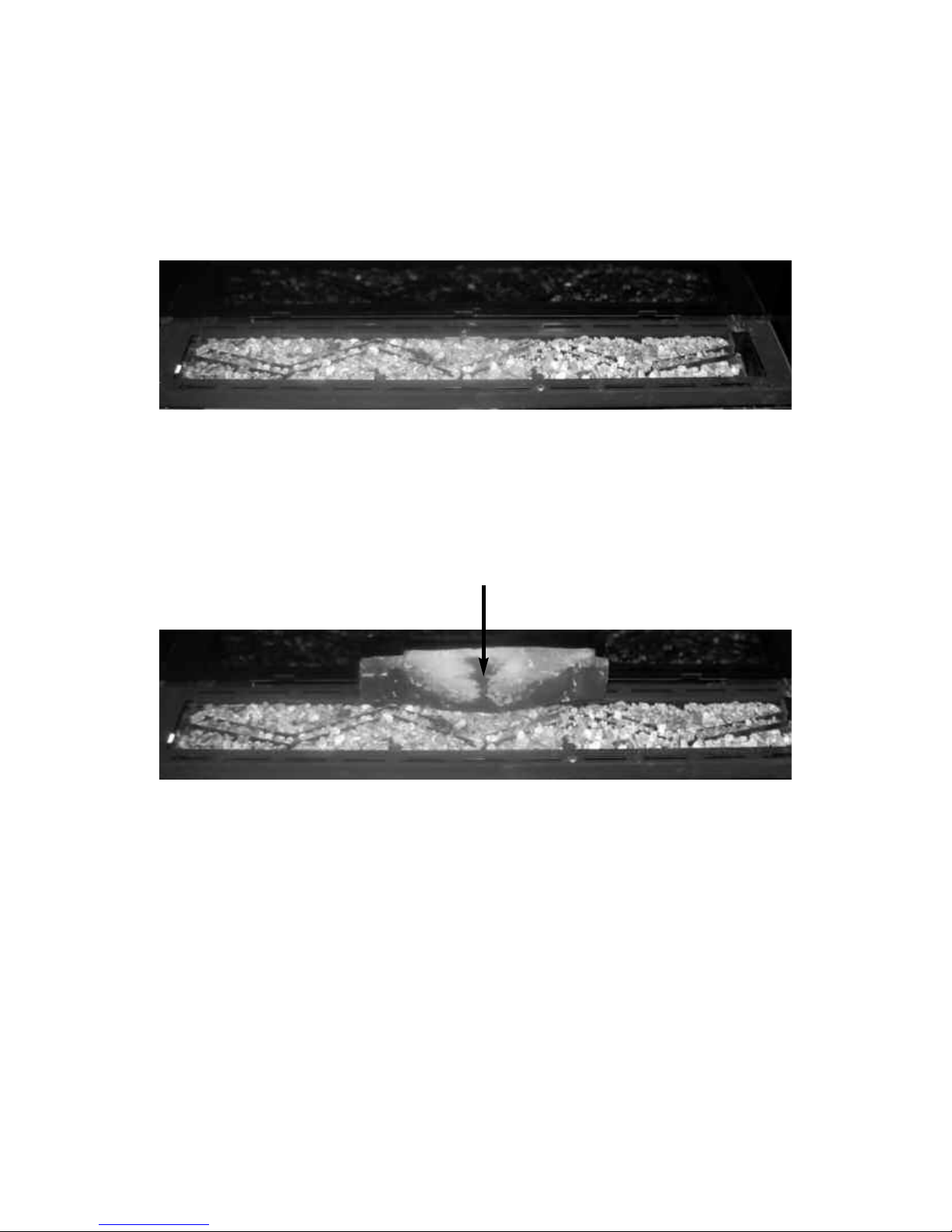
5.5 RE-LAYING THE FUEL-BED
5.5.1 Lay an even layer of vermiculite material across the burner tray as
shown below in figure 13.
Fig. 13
5.5.2 Place log “A” in a central position as shown below in figure 14, using
the location hole on the base of the log to position in line with the
location peg on the burner.
Fig. 14
45
Log A
Page 47
46
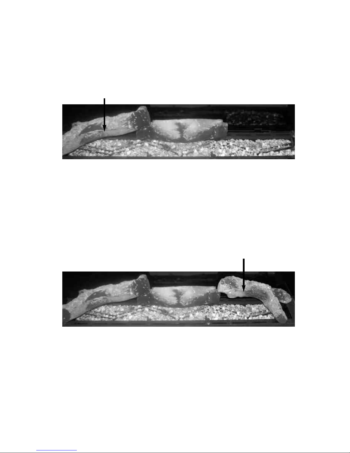
5.5.3 Place log “B” in position at the left hand side of the burner as shown
below in figure 15, using the cut out on the left hand side of log “A” as a
guide for placement and the locating lug at the LHS of the fuel tray.
Fig. 15
5.5.4 Place log “C” in position at the right hand side of the burner as shown
below in figure 16, using the cut-out on the right hand side of log “A” as
guide for placement.
Fig. 16
L
og B
Log C
Page 48
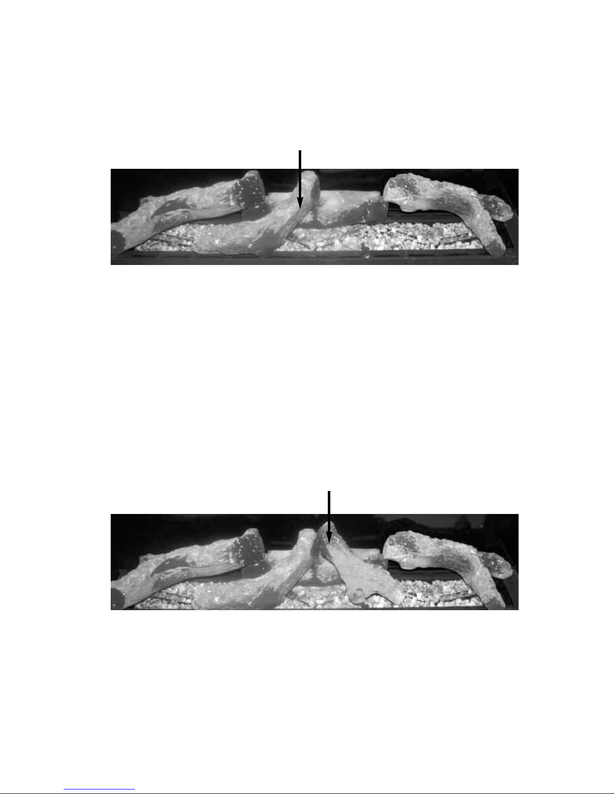
5.5.5 Place log “D” in position at the centre left hand side of the burner as
shown below in figure 17, using the locating peg at the front of the
burner and positioning on log “A” as shown.
Fig. 17
5.5.6 Place log “E” in position at the centre right hand side of the burner as
shown below in figure 18, using the locating peg at the front of the
burner and positioning on log “A” as shown.
Fig. 18
47
Log D
Log E
Page 49
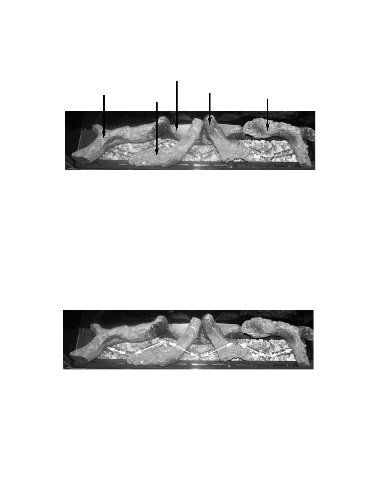
5.5.7 As a final check ensure that the logs are layed correctly as shown
below in figure 19.
Fig. 19
5.5.8 If required fit the embaglow material over the flame ports. To do this
seperate into short strands and place randomly over the flame porting
area as indicated by the arrows below in figure 20. This material is
only supplied to improve flame aesthetics and is optional to install.
Fig. 20
48
Log D
Log E
Log B
Log C
Log A
Page 50

5.5.9 Re-fit the glass frame assembly before proceeding.
Warning : Use only the log fuel-bed supplied with the fire. When replacing
the log fuel-bed remove the old log fuel-bed and discard it. Fit a complete
log fuel-bed from the manufacturer, only use genuine replacements.
THE FOLLOWING STATEMENT IS APPLICABLE TO ALL FUEL-BED TYPES
This appliance uses fuel effect pieces containing Refractory Ceramic Fibres (R.C.F.),
which are man-made vitreous silicate fibres. Excessive exposure to these materials
may cause temporary irritation to eyes, skin and respiratory tract. Consequently, it
makes sense to take care when handling these articles to ensure that the release of
dust is kept to a minimum. To ensure that the release of fibres from these R.C.F. articles is kept to a minimum, during installation & servicing we recommend that you use
a HEPA filtered vacuum to remove any dust and soot accumulated in and around the
fire, before and after working on the fire. When replacing these articles we
recommend that the replaced items are not broken up, but are sealed within a heavy
duty polythene bag, clearly labelled as “RCF waste”. This is not classified as
“hazardous waste” and may be disposed of at a tipping site licensed for the disposal
of industrial waste. Protective clothing is not required when handling these arrticles,
but we do recommend you follow the normal hygiene rules of not smoking, eating or
drinking in the work area, and always wash your hands before eating or drinking.
This appliance does not contain any component manufactured from
asbestos or asbestos related products.
5.6 CLEANING - WARNING
Before attempting any cleaning operation ensure that the fire has been allowed to
fully cool. Black painted metal parts should be gently cleaned with a damp cloth.
This product is equipped with non-reflective glass which must be cleaned as
follows or irrepairable damage to the coating on the glass panel will occur. The
manufacturers warranty will not cover damage by incorrect cleaning methods.
DO NOT USE ceramic glass cleaning agents.
DO NOT USE sharp objects or blades to remove marks.
DO NOT USE dry cloths or wipes.
DO USE normal glass cleaner such as “Sidolin”.
DO USE soft glass wipes.
DO USE damp cloths.
PLEASE NOTE
:- The glass will require cleaning periodically. Condensation
produced by the products of combustion will create marks on the inside face of the
glass panel.
49
Page 51

5.6 (CONT.) CLEANING THE FUELBED
We do not recommend cleaning of the logs or fuelbed components as these are
fragile and damage may result. None of these parts must be washed or
exposed to any cleaning agents or water. Any damaged parts must be
replaced by contacting your dealer or telephoning BFM Europe Ltd. on the number
stated on the rear cover of this book. The log fuel-bed must only be replaced with
a complete and genuine replacement item and the fire must never be run with a
damaged item. The fuel-bed must be carefully fitted as stated in section 5.5
5.7 USER REPLACEABLE PARTS
The only user replaceable parts on this fire are the fuelbed components and
logs which may be replaced as described in the above section. Replacement of
any other parts must be carried out by a competent person such as a GAS SAFE
registered gas installer. The part numbers of the user replaceable parts are as
follows, these are available from BFM Europe Ltd. who may be contacted at the
number on the rear cover of this book.
Glass frame assembly 1177-179340
Complete log set B-182450
Log “A” only B-184680
Log “B” only B-184690
Log “C” only B-184700
Log “D” only B-184710
Log “E” only B-184720
Emba-glow material B-120070
Bag of vermiculite CV-107116
Handset wall bracket B-126410
5.8 REPLACING THE BATTERIES IN THE FIRE
5.8.1 The product is supplied with a battery pack that is positioned at the front
left hand side of the fire as shown below in figure 21.
5.8.2 Locate the battery pack by lifting away the lower infill, remove the screw
that holds the cover onto it and fit the 4 off AA sized batteries supplied
in the loose items pack.
Fig. 21
50
Page 52

Due to our policy of continual improvement and development the exact
accuracy of descriptions and illustrations cannot be guaranteed.
Part No. B-1004690
Issue 1
BFM Europe Ltd.
Trentham Lakes
Stoke-on-Trent
Staffordshire
ST4 4TJ
www.bfm-europe.com
Telephone - General Enquiries : (01782) 339000
Telephone - Service : (01782) 339008
 Loading...