

Page 1

HOW TO BUILD
YOUR
PLYFLY GO-KART!
For Ages 12+
PlyFly Go‑Kart Instruction Guide • 2015 Release
Page 2
Thank you for supporting
the FLATWORKS Kickstarter campaign.
Your contribution is a great help, and your
support is much appreciated.
Thank you
Enjoy your new Plyfly Go‑Kart!
Check back soon and see what else we make!
We hope you’re as excited to get
started on your new adventure as we are to
be working on the FLATWORKS.
the Flatworks Crew,
&
150718 PLYFL Y rev A_Cover | A ug u st 7 , 2 01 5 5: 0 6 P M
II
Page 3

Steven Hynes
Cam McCulloch
Alan Miyasaki
Stephan Schnitker
Chris Patton
Joe Barton
Liam Newman
No Regrets
David Geisinger
Ken Short
Andrew B. Bartels
Brian Kaleida
Matthew & Keri
Zee
Ray Colwell
Henry E.
Carl Moulton
Mark ChengIan
Drummond
CJBCN
James “Udub” Underwood
Jesse Cannone
Luke
Jim Mahoney
Tim Baker
Karl Eberhardt
Tom a s Petr u
David Moore
Jim
K Brotman
Dennis Cox
Chris DePerro
Family Woo
Marcus Leef
Anonymous
Michael Lindahl
JouleLee
Tiegen
Tyr a Hamme t t
Nathan Pelsor
Douglas Dayton
Sam Bowling
Lindsey Zimmerman
Anthony
Joshua Marcus
Lindsay Lauber
Joseph Asti
Nick Vines
Herk
Brian Jepson
Steve Baker
Louis Tovar
Mar k Tracy
Joe W.
Greg Brncick
Grandpa Rex
Alex Gomes
Mohit
Sam Bell
Emily H.
Andrew Marc
Tim Owens
Chris Porter
Matthew Clark
Ryan Bradley
Michael Lindahl
Adam “Hock” Hocherman
Michael McGrath
Dave Krugman
Daniel Cianci
Scott Newman
Russ Kadooka
Mitch
Bob
150718 PLYFL Y rev A_Cover | A ug u st 7 , 2 01 5 5: 0 6 P M
III
Page 4
What's Inside?
1 Exploring the kit 1
Warnings and safety 2
Handling and storage 2
Why Wood? 3
Good to know 3
What’s in the kit? 3
Unpacking the boxes 4
2 Getting Started 6
Getting started 7
Recommended tools 7
Chisel & hammer method 7
Reciprocating saw method 7
3 Seat Assembly 8
Plywood sheet reference 9
Recommended tools 9
Required hardware 9
Required wooden parts 10
Assembling the seat 11
4 Steering Column Assembly 12
Plywood sheet reference 13
Recommended tools 13
Required hardware 13
Required wooden parts 13
Assembling the steering shaft 14
5 Steering Rack Assembly 15
Plywood sheet reference 16
Recommended tools 16
Required hardware 16
Required wooden parts 17
Assembling the steering rack 17
6 Fixed Steering Column Assembly 18
Plywood sheet reference 19
Recommended tools 19
Required hardware 19
Required wooden parts 20
Assembling the steering column 20
7 Steering Spindle Assemblies 21
Plywood sheet reference 22
Recommended tools 22
Required hardware 22
Required wooden parts 23
Assembling the left & right steering spindles 24
8 Pedal Assemblies 25
Plywood sheet reference 26
Recommended tools 26
Required hardware 26
Required wooden parts 27
Assembling the gas & the brake pedals 27
9 Frame Assembly 28
Plywood sheet reference 29
Recommended tools 30
Required hardware 30
Required assemblies 30
Required wooden parts 31
Assembling the frame 32
10 Putting the go‑kart together 37
Overview of the recommended tools 38
Overview of the required hardware 38
Overview of the required but not provided 41
Overview of the required wooden parts 41
Overview of the required assemblies 41
Part 1 Install the rear axle 43
Part 2 Install the brake caliper 44
Part 3 Install the steering column assembly 45
Part 4 Install the steering spindles 46
Part 5 Install the gas & brake pedals 47
Part 6 Install the gas & brake cables 49
Part 7 Install the engine and drive train 52
Part 8 Install the wheel assemblies 57
Part 9 Install the seat assembly 58
Part 10 Install the fairings 59
11 Master List 60
Visual reference of the plywood sheets 61
List of the wooden parts 62
List of the wooden assemblies 66
List of the tools needed 67
List of loose contents 68
List of the packaged contents 70
12 Legal 72
Legal 73
13 Terms & Conditions 74
Terms & Conditions of Purchase and Use 75
1 5 0 7 1 8 P LY F LY r e v A _ T O C | August 7, 2015 5:06 PM
IV
Page 5

1
Exploring the kit
Introduction
Each Plyy Go-Kart kit arrives in 3 boxes.
Review the contents of each box to ensure you have all the
necessary parts to begin building your next adventure!
1 5 0 7 1 8 P LY F L Y r e v A _ C H 1 | August 7, 2015 5:08 PM
1
Page 6

Warnings and safety
Riding karts can be dangerous.
Please use caution and prudence and follow the
guidelines below.
• Avoid operating your kart in crowded or conned areas.
• Any children that use the kart are of an appropriate
age and do so under proper supervision.
The recommended age for this kart is 12+.
• Avoid using your kart near any other vehicular trac or
on public roads.
• Never try to t more than one person in the kart.
• Always wear a DOT‑rated helmet and gloves while
operating the kart.
• Never aim the kart at other people, objects or animals.
• Prior to riding, every rider should familiarize
themselves with:
‒ Their environment
‒ Any obstacles or dangers.
‒ The location and function of the
emergency shuto switch.
• Inspect the kart prior to each run to make sure that each
element is properly functioning. Test:
‒ Brakes lock the rear wheel.
‒ Shut o switch kills engine.
‒ Clutch, chain, sprocket and sprocket guard are
properly tightened and functioning.
‒ The wheels are all on and tightened.
‒ The steering system is functioning properly.
‒ There are no areas of brake discs, wheels, chain or
other moving elements rubbing on the wood.
‒ That all shaft keys (clutch, sprocket, brake disc, wheels)
are installed and secured in place by a tight set screw.
‒ Ensure all fasteners are tight and properly torqued.
‒ The safety ag is installed.
‒ The seat is properly installed and adjusted.
• Do not attempt to leave the ground with the kart.
It is not designed or intended for jumping.
• Ensure the rider has no articles of loose clothing
or hair that could get caught in the spinning
mechanisms of the kart.
Handling and storage
• The kart is heavy.
• Use at least two people to lift or move it.
• Some surfaces may be hot after use, handle with
caution. These may be from friction in bearings and
brakes or from the engine.
• If gasoline is spilled on the wood, leave the kart
outside in a well ventilated area to dry before use
or storage. Be very careful about exposure to potential
ignition sources until it dries.
• Do not tip the kart. Fuel may spill from the carburetor if
inclined too much. If you need to stand up the kart, start
the engine and turn o the fuel valve. Let the engine run the
carburetor dry.
• Store the kart in a dry, clean area and coat the wood with
a paint or coating for the longest life.
1 Exploring the kit
2
1 5 0 7 1 8 P LY F L Y r e v A _ C H 1 | August 7, 2015 5:08 PM
Page 7
Why Wood?
Sure, steel karts are fun and strong, but they require a large
number of specialized tools to build, repair or modify. Tools
that most people don’t have. Wood, on the other hand, can
be crafted with tools available in most homes and all home
improvement stores. We want to provide kits that people
can make their very own, by painting, xing or modifying and
wood is a natural t for this.
The wood used in this kit is a 3/4 inch Baltic Birch plywood.
It is a natural t for the go-kart due to it’s strength and
appearance. The 13 plies make it incredibly strong and
give the end grain a beautiful contrast. Best of all, it can be
modied, repaired or reworked with common household
tools.
Good to know
It is vitally important that anyone riding a go‑kart wear the
proper protective gear. The rider should wear, at a minimum,
a full‑face DOT‑rated engine cycle helmet, gloves and a
helmet supporting neck brace. These items and other safety
equipment are not supplied with the kits but can be found
through many online or retail sellers.
We aim to provide the best assembly documentation in
the industry and will include written instructions and online
videos for all of the crucial steps. We will be available to
help you through the process, so if you need assistance,
please ask. However, this is a kit and the ultimate
build quality is up to you.
What’s in the kit?
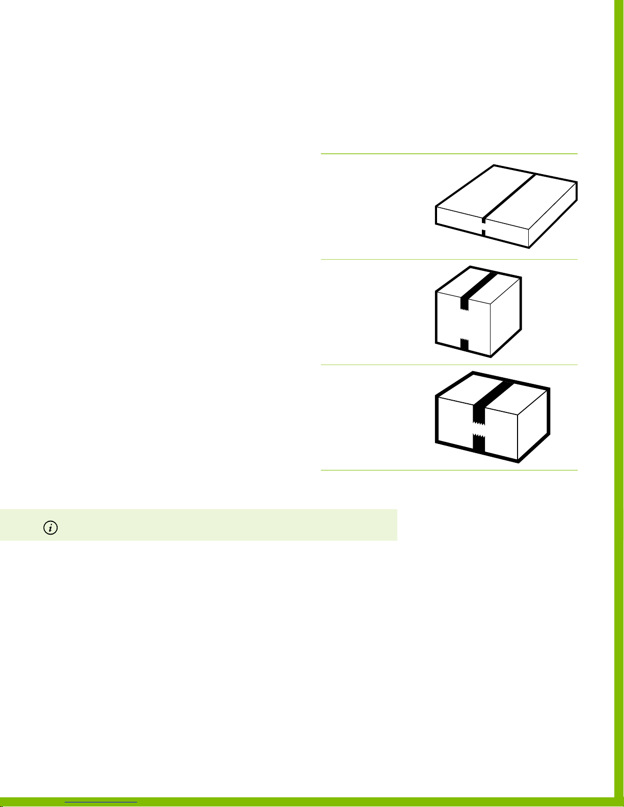
Each Plyy Go-Kart kit arrives in 3 boxes. Box 1 is a at box
with the wooden structural parts. Box 2 is the engine and
box 3 is the hardware.
1.2.3. That’s it!
Packaging reference
Description Reference
Box 1 – wood
Dimension: 30” x 60” x 3”
Box 2 –engine
Dimension: 14” x 14” x 16”
Box 3 – hardware & wheels
Dimensions: 24” x 12” x 12”
For more the complete list of hardware, see Visual reference of the plywood sheets, on page 61.
1 5 0 7 1 8 P LY F L Y r e v A _ C H 1 | August 7, 2015 5:08 PM
PlyFly Go‑Kart Instruction Guide • 2015 Release
3
Page 8

Unpacking the boxes
Each box should have the following components.
Box 1 contents
2.5 HP 4.0 HP 4.0 HP 4 .0 HP 4.0 HP
№ DESCRIPTION
3 Plywood Sheet
3/4” depth
1 Plywood Sheet
1/4” de pth
SINGLE WHEEL
10” WHEELS
• • • • •
• • • • •
SINGLE WHEEL
10” WHEELS
SINGLE WHEEL
12” WHEELS
LIVE AXLE
10” WHEELS
LIVE AXLE
12” WHEELS
1 Flag
1 Drive Shaft
Steel, Keyed, 5/8” D
Box 2 contents
№ DESCRIPTION
1 Gas Powered Engine
2.5 HP MODEL
1 Gas Powered Engine
4.0 HP MODEL
• • • • •
18” L 18” L 18” L 33” L 36” L
2.5 HP 4.0 HP 4.0 HP 4 .0 HP 4.0 HP
SINGLE WHEEL
10” WHEELS
•
―
SINGLE WHEEL
10” WHEELS
― ― ― ―
SINGLE WHEEL
12” WHEELS
LIVE AXLE
10” WHEELS
• • • •
LIVE AXLE
12” WHEELS
1 Exploring the kit
4
1 5 0 7 1 8 P LY F L Y r e v A _ C H 1 | August 7, 2015 5:08 PM
Page 9

Box 3 Contents
DESCRIPTION
2.5 HP 4.0 HP 4.0 HP 4.0 HP 4.0 HP
SINGLE WHEEL
10” WHEELS
SINGLE WHEEL
10” WHEELS
SINGLE WHEEL
12” WHEELS
LIVE AXLE
10” WHEELS
LIVE AXLE
12” WHEELS
Plyy Packaged Hardware Kit Sealed kit of go ‑kart hardware
Clutch #35 Chain, 11 Tooth Pulley for 5/8” shaft 2.5 HP Model
Clutch #35 Chain, 12 Tooth Pulley for 3/4” shaft 4.0 HP Model ―
Clutch Guard Side Engine Mounting Plate
Clutch Guard Top Top C ove r
Clutch Guard Cover Outside Cover
Sprocket 60 Tooth, #35 Chain, 5/8” D bore
Roller Chain #35 Chain, 29‑5/8” L
Chain Link For connecting #35 Roller Chain
Control Cable 1/16” D, throttle & brake control cable
Red Throttle Cable Brake conduit, 5’ L
Green Throttle Cable Gas conduit, 6’ L
VXB Mounted Bearing 5/8” ID
Brake Caliper
1 1 1 1 1
1
― ― ― ―
1 1 1 1
1 1 1 1 1
1 1 1 1 1
1 1 1 1 1
1 1 1 1 1
1 1 1 1 1
1 1 1 1 1
2 2 2 2 2
1 1 1 1 1
1 1 1 1 1
3 3 3 3 3
1 1 1 1 1
Brake Disc
Brake Hub
Long Hex Bolt Grade 5, 5/8”‑11, 11” L Single Wheel Kit Only
Shor t Hex Bolt Grade 5, 5/8”‑11, 6.5” L
Precision Rod 1/4” D, 18” L
Drawer Slide Hardware included, 10” L
Green Elastic Cord 3/16” OD, 18”
Spax Screw 1 Box,#8 1‑1/2” L
10” D Wheels Rear driven wheel
10” D Wheels Undriven wheel
12” D Wheels Rear driven wheel ― ―
12” D Wheels Undriven wheel ― ―
PlyFly Flag
1 1 1 1 1
1 1 1 1 1
1 1 1
4 4 4 4 4
1 1 1 1 1
1 1 1 1 1
1 1 1 1 1
1 1 1 1 1
1 1
3 3
1 1 1 1 1
― ―
―
―
1
3
2
2
―
―
―
―
2
2
1 5 0 7 1 8 P LY F L Y r e v A _ C H 1 | August 7, 2015 5:08 PM
For more the complete list of hardware, see List of the packaged contents, on page 70.
PlyFly Go‑Kart Instruction Guide • 2015 Release
5
Page 10

2
Getting Started
Introduction
Preparing for a Plyy Go-Kart build, you will need to cut out
each structural wooden part from the plywood sheets.
The more time spent trimming tabs cleanly will save
a lot of sanding time.
1 5 0 7 1 8 P LY F L Y r e v A _ C H 2 | August 7, 2015 5:08 PM
6
Page 11
Getting started
Chisel & hammer method
INSTRUCTIONS
1. Open the provided boxes to ensure all the parts are
included.
2. To release the structural wooden parts from the
plywood sheets, use the recommended tools and follow
one of the suggested methods:
‒ A chisel and hammer method
‒ The reciprocating saw method
Recommended tools
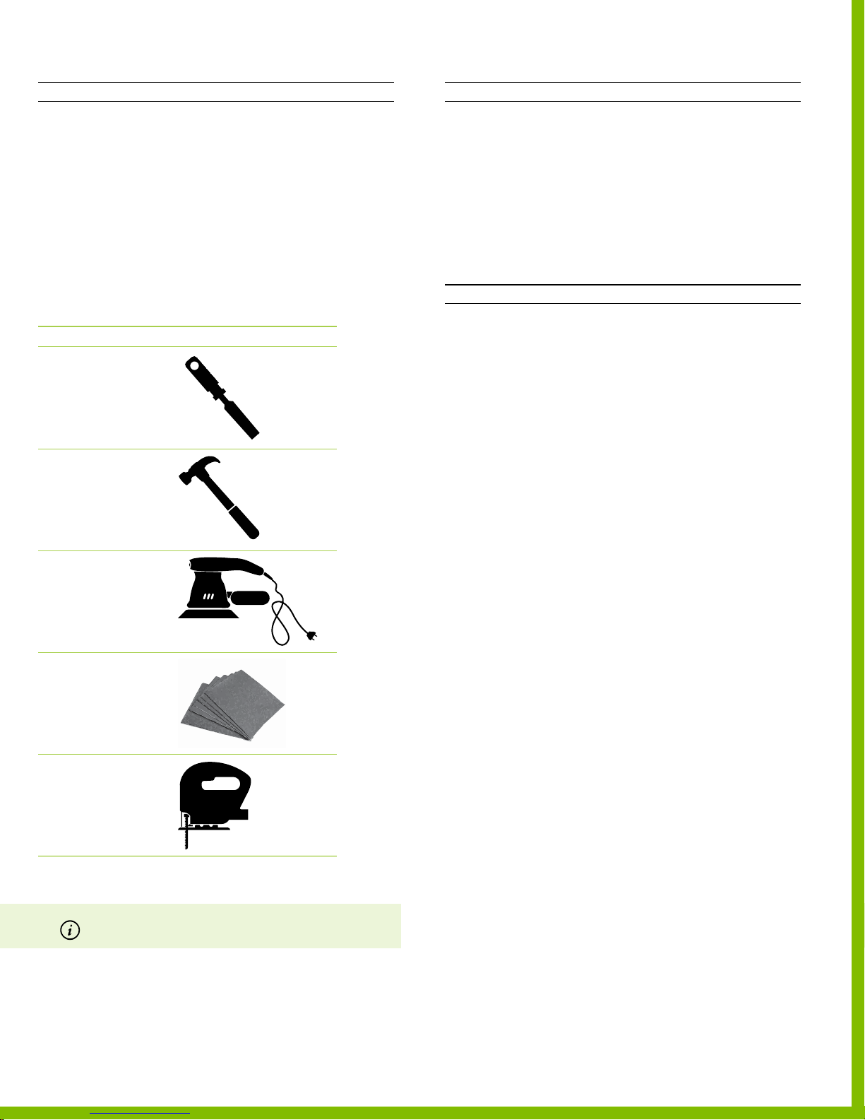
DESCRIPTION REFERENCE
Chisel
Hammer
Orbital sander
INSTRUCTIONS
1. To free a part from the plywood sheet, place the at side
of chisel against the keeper side of the part.
2. Strike the top of the chisel sharply with a hammer to
remove wood from the notches.
3. Repeat this procedure until all the parts are free.
4. To nish the edges of all the wood parts that become
spalled or rough from the cutting process using an orbital
sander, or sheet of sandpaper.
Reciprocating saw method
INSTRUCTIONS
1. Select the correct blade for the cutting wood
2. Place the plywood sheet on saw horses or a workbench,
or clamp it in a vice, depending on which is best suited for
your purpose.
Note Make sure you have sucient light to see your cutting
marks easily
3. To free a part from the plywood sheet, position the blade
close to the edge of the wood tab (where you will begin
your cut)
Note Complete the cut by continuing through the material,
being careful to support any piece that may drop when the cut is
nished until the blade is free of it.
4. Repeat this procedure until all the parts are free.
5. To nish the edges of all the wood parts that become
spalled or rough from the cutting process using an orbital
sander, or sheet of sandpaper.
Sandpaper
Jigsaw or
Reciprocating saw
(optional)
For more information on What’s in the kit?, see page 3.
1 5 0 7 1 8 P LY F L Y r e v A _ C H 2 | August 7, 2015 5:08 PM
PlyFly Go‑Kart Instruction Guide • 2015 Release
7
Page 12
3
3
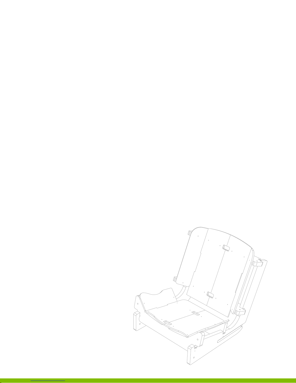
Seat Assembly
Assembly
Introduction
Before beginning this assembly, be sure to chisel out and sand
parts 22 ‑ 33. These 12 components are required to fully assemble
the go‑kart seat
1 5 0 7 1 8 P LY F LY r e v A _ S e a t | August 7, 2015 5:06 PM
8
Page 13
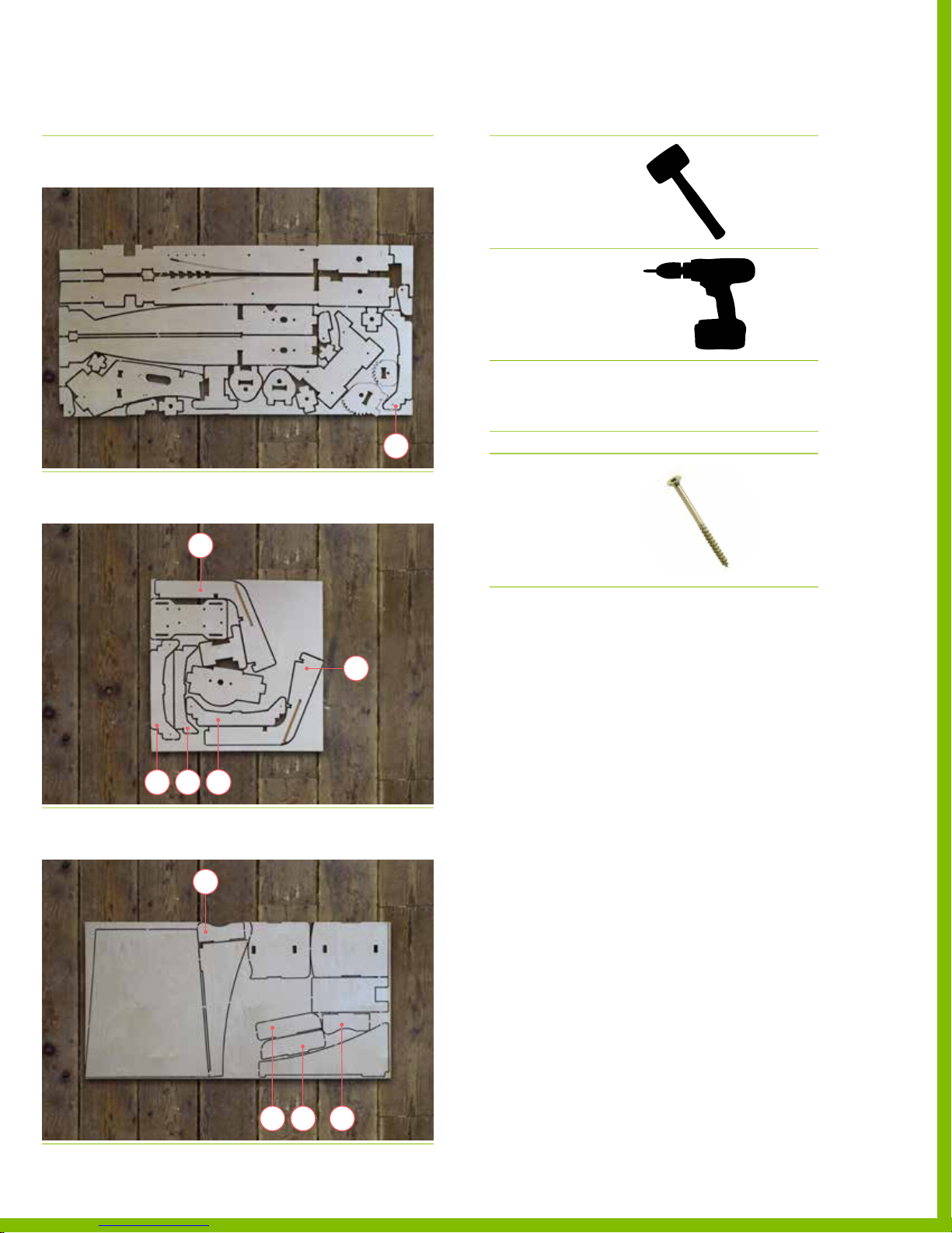
Plywood sheet reference
DESCRIPTION REFERENCE
Recommended tools
DESCRIPTION REFERENCE
Sheet 1
3/4” Plywood Sheet
Sheet 3
3/4” Plywood Sheet
‒ Parts 24
‒ Parts 22‑23
‒ Parts 25‑27
22
24
Dead blow hammer
or mallet
Electric driver
Required hardware
№ DESCRIPTION REFERENCE
32 Spax Screw
#8, 1‑1/2” L
PN 12 519
Sheet 4
1/4” Plywood Sheet
1 5 0 7 1 8 P LY F LY r e v A _ S e a t | August 7, 2015 5:06 PM
23
252726
‒ Parts 28‑31
31
302829
PlyFly Go‑Kart Instruction Guide • 2015 Release
9
Page 14
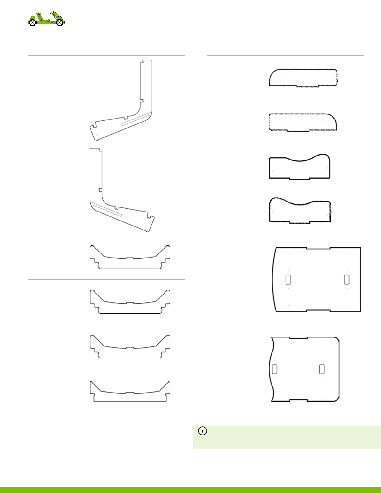
Required wooden parts
DESCRIPTION REFERENCE
Part 22
Seat Side Left
PLYWOOD SHEET 3
Part 23
Seat Side Right
‒ Gas tank side
PLYWOOD SHEET 3
DESCRIPTION REFERENCE
Part 28
Seat Bolster Left
PLYWOOD SHEET 4
Part 29
Seat Bolster Right
PLYWOOD SHEET 4
Part 30
Seat Thigh Bolster Left
PLYWOOD SHEET 4
Part 31
Seat Thigh Bolster Right
PLYWOOD SHEET 4
Part 24
Seat Crossbar
PLYWOOD SHEET 1
Part 25
Seat Crossbar
PLYWOOD SHEET 3
Part 26
Seat Crossbar
PLYWOOD SHEET 3
Part 27
Seat Crossbar Bracket
PLYWOOD SHEET 3
Part 32
Seat Back
PLYWOOD SHEET 4
Part 33
Seat Bottom
PLYWOOD SHEET 4
1 5 0 7 1 8 P LY F LY r e v A _ S e a t | August 7, 2015 5:06 PM
Note If you received a 1/4” plywood sheet that is nished on one side and
you intend to paint the Plyy go-kart seat; reverse the wooden parts 28-33
(so the unnished side is outward facing and
ready to receive paint).
3 Seat Assembly
10
Page 15
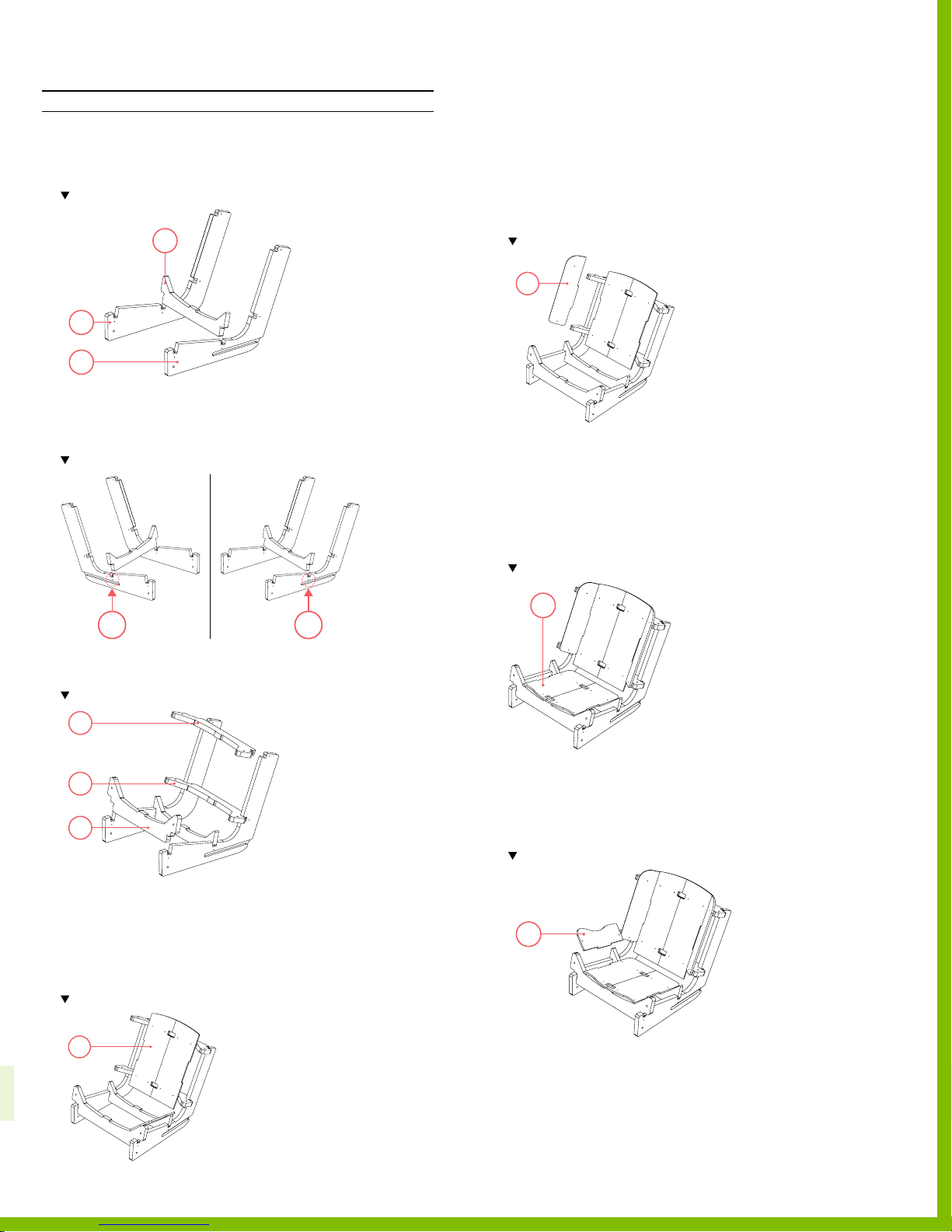
Assembling the seat
INSTRUCTIONS
1. Align parts 22 & 23 with the slots facing outwards.
2. Using a mallet, tap part 27 into the slots on parts 22 &23.
Note the part orientation and location.
27
23
22
3. Secure part 27 using 2 screws.
‒ Use 1 screw per side.
‒ Total of 2 locations, 2 screws.
Note secure pa rt 27, by screwing the par t in from the outside of par t 22 & 23.
7. Secure part 32 to the seat frame using screws.
‒ Use 8 screws.
‒ Total of 8 locations.
8. Using a mallet, tap part 29 into seat frame.
Note location and orientation of part 29.
29
9. Repeat step 8 with part 28 on the opposite side.
10. Secure parts 28 & 29 to seat frame using screws.
‒ Use 4 screws.
‒ Total of 4 locations.
11. Using a mallet, tap part 33 into the tab connections of
parts 26 &27.
Note location and orientation of part 33.
21
4. Using a mallet, tap parts 24, 25, & 26 into the
remaining slots.
Note the location and orientation of the parts 24-26.
24
25
26
5. Secure parts 24, 25, & 26 by using screws.
‒ Use 2 screws per part, 1 screw per side.
‒ Total of 6 locations, 6 screws.
6. Using a mallet, tap part 32 into the tab connections of
parts 24 & 25.
Note the location and orientation of the part 32.
32
1 5 0 7 1 8 P LY F LY r e v A _ S e a t | August 7, 2015 5:06 PM
33
12. Secure part 33 using screws.
‒ Use 8 screws.
‒ Total of 8 locations.
13. Using a mallet, tap part 31 into place using a mallet.
Note location and orientation of part 31.
31
14. Repeat step 13 with part 30 on the opposite side.
15. Secure parts 30‑31 to seat frame using screws.
‒ Use 4 screws.
‒ Total of 4 locations.
PlyFly Go‑Kart Instruction Guide • 2015 Release
11
Page 16
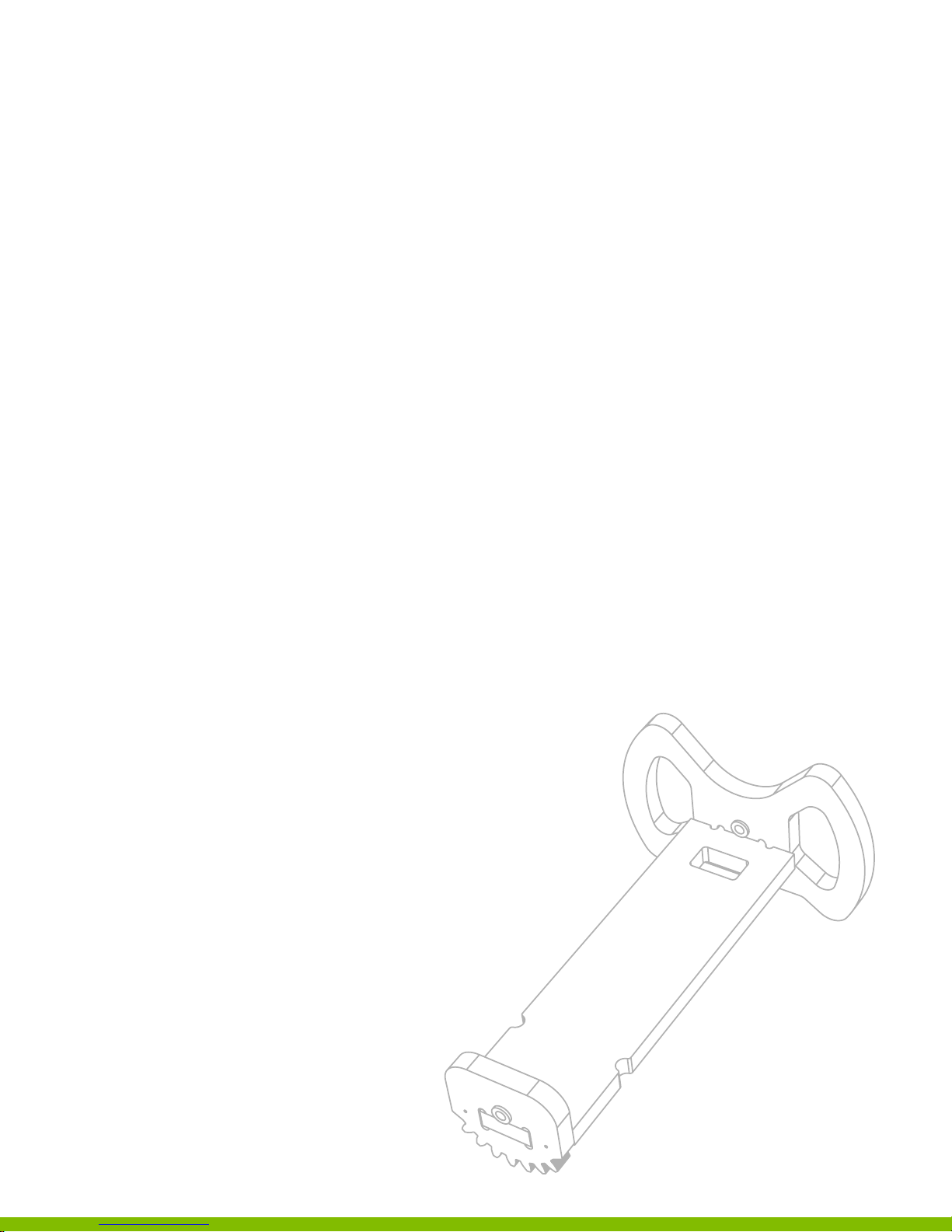
Steering Column
4
Assembly
Introduction
Before beginning this assembly, be sure to chisel out and
sand parts 19‑20. These 3 components are required to
fully assemble the steering shaft.
150718 PL YFLY rev A_Steer column | A ug u st 7 , 2 01 5 5 : 06 P M
12
Page 17
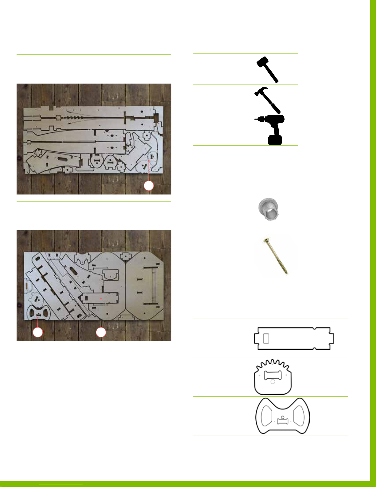
Plywood sheet reference
DESCRIPTION REFERENCE
Recommended tools
DESCRIPTION REFERENCE
Sheet 1
3/4” Plywood Sheet
Sheet 2
3/4” Plywood Sheet
‒ Part 20
‒ Part 19
‒ Part 21
20
Dead blow hammer
or mallet
Hammer
Electric driver
Required hardware
№ DESCRIPTION REFERENCE
4 Small Metal Bushing
Flanged 3/8” ID, 1/4” L
PN 12 53 8
521 19
4 Spax Screw
#8, 1‑1/2” L
PN 12 519
Required wooden parts
DESCRIPTION REFERENCE
Part 19
Steering Column Shaft
PLYWOOD SHEET 2
Part 20
Steering Pinion
PLYWOOD SHEET 1
Part 21
Steering Wheel
PLYWOOD SHEET 2
150718 PL YFLY rev A_Steer column | A ug u st 7 , 2 01 5 5 : 06 P M
PlyFly Go‑Kart Instruction Guide • 2015 Release
13
Page 18
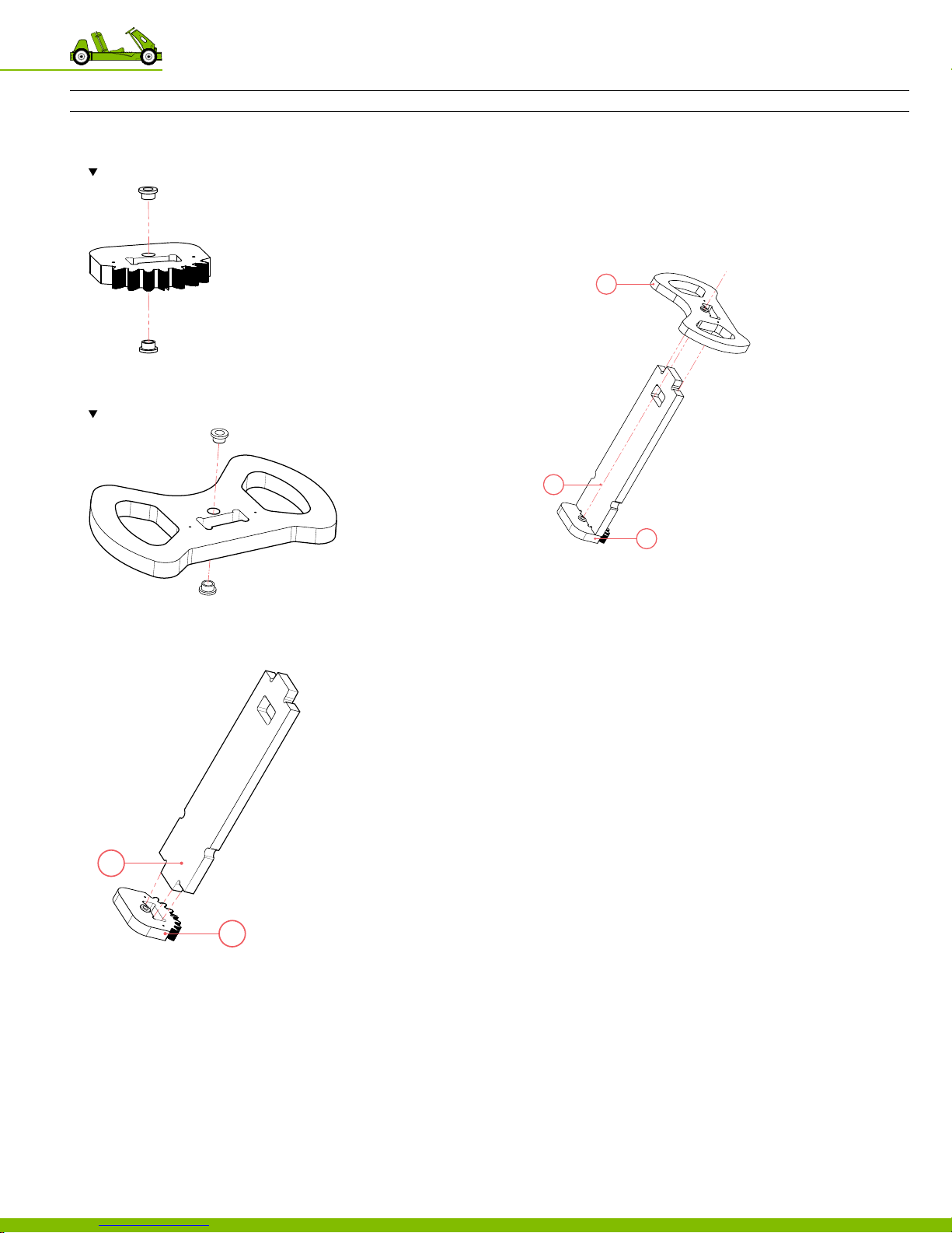
Assembling the steering shaft
20
19
INSTRUCTIONS
1. Press bushings into each side of part 20.
Note there are 2 bushings, 1 bushing per side.
2. Hammer securely until the top of each bushing is ush.
3. Press bushings into each side of part 21.
Note there are 2 bushings, 1 bushing per side..
6. Secure the parts using screws.
‒ Use 2 screws on part 20
‒ Total of 2 locations.
7. Using a mallet, tap part 21 to the assembly.
Note the location and orientation of par t 21.
The bushings should point in the sa me direction.
21
19
20
4. Hammer securely until the top of each bushing is ush
5. Using a mallet, tap part 19 to part 20.
Note The orientation of the par ts.
8. Secure the parts using screws.
‒ Use 2 screws on part 21.
‒ Total of 2 locations.
150718 PL YFLY rev A_Steer column | A ug u st 7 , 2 01 5 5 : 06 P M
4 Steering Column Assembly
14
Page 19
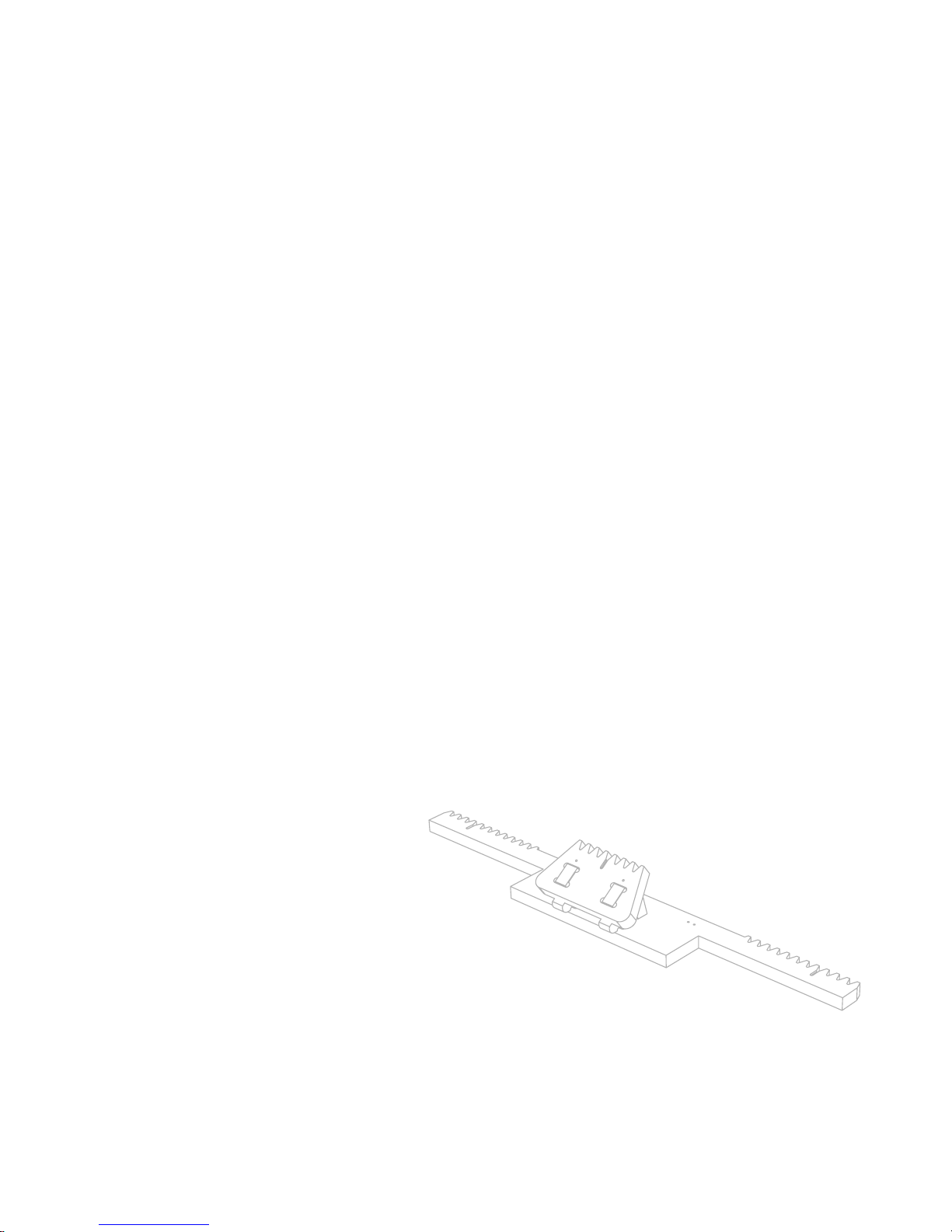
Steering Rack
5
Assembly
Introduction
Before beginning this assembly, be sure to pre‑cut and sand
parts 9 ‑ 12. These 4 components are required to fully assemble
the go‑kart steering rack.
150718 PLYFL Y rev A_Steer rack | A u gu s t 5 , 2 01 5 1 0: 3 8 P M
15
Page 20
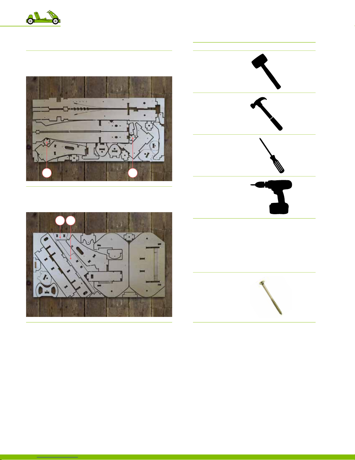
Plywood sheet reference
DESCRIPTION REFERENCE
Recommended tools
DESCRIPTION REFERENCE
Sheet 1
3/4” Plywood Sheet
Sheet 2
3/4” Plywood Sheet
12 11
‒ Parts 9‑10
‒ Parts 11‑12
Dead blow hammer
or mallet
Hammer
Screwdriver
109
Electric driver
Required hardware
№ DESCRIPTION REFERENCE
4 Spax Screw
#8, 1‑1/2” L
PN 12 519
150718 PLYFL Y rev A_Steer rack | A u gu s t 5 , 2 01 5 1 0: 3 8 P M
5 Steering Rack Assembly
16
Page 21
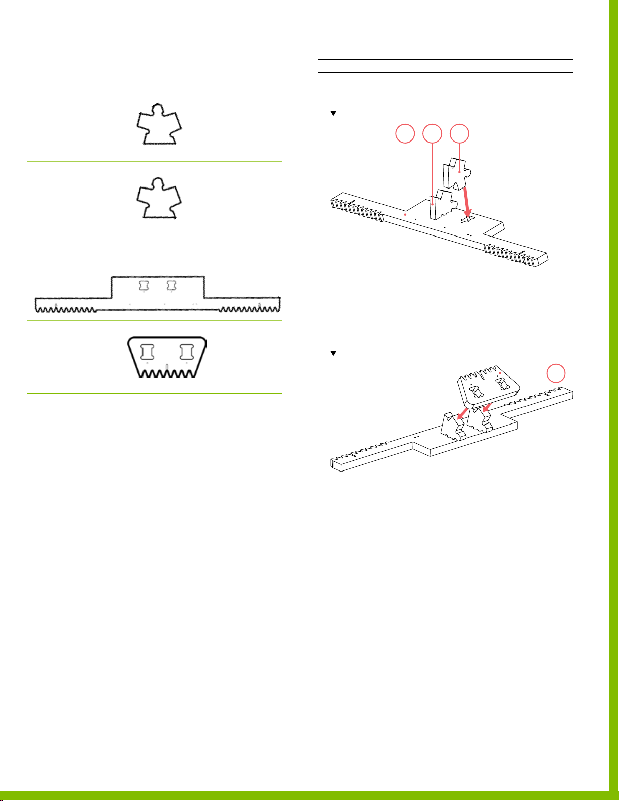
Required wooden parts
DESCRIPTION REFERENCE
Part 9
Steering Rack Bracket
PLYWOOD SHEET 1
Part 10
Steering Rack Bracket
PLYWOOD SHEET 1
Part 11
Steering Rack
PLYWOOD SHEET 2
Part 12
Steering Rack Center
Bracket
PLYWOOD SHEET 2
Assembling the steering rack
INSTRUCTIONS
1. Using a mallet, tap parts 9 & 10 into the slots on part 11.
Note the part ori entation
9 1011
2. Secure parts 9 & 10 using screws.
‒ Use 1 screw per part.
‒ Total of 2 locations, 2 screws.
3. Using a mallet, tap part 12 into the tab connections on
parts 9 & 10.
Note the part 12 orientation – the gear teeth should point in the same direction.
12
150718 PLYFL Y rev A_Steer rack | A u gu s t 5 , 2 01 5 1 0: 3 8 P M
4. Secure part 12 to the assembly using screws.
‒ Use 2 screws.
‒ Total of 2 locations.
PlyFly Go‑Kart Instruction Guide • 2015 Release
17
Page 22
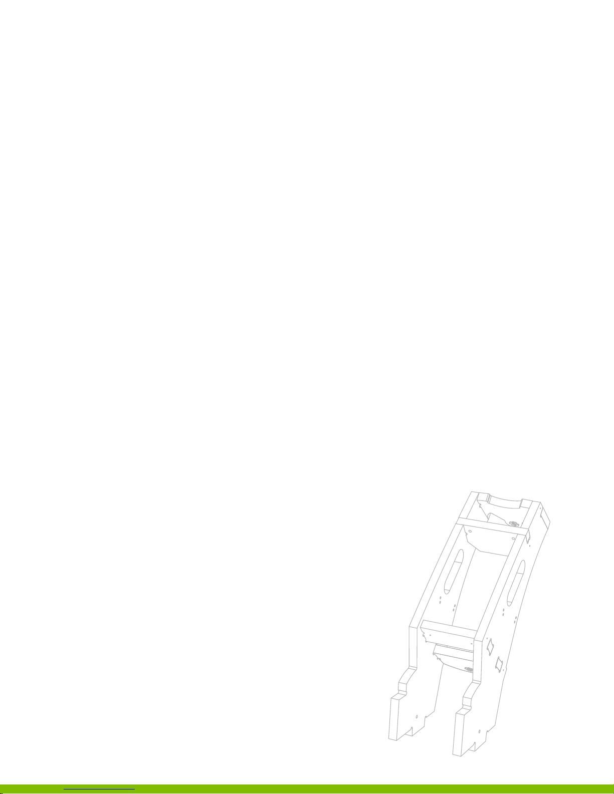
Fixed SteeringColumn
6
Assembly
Introduction
Before beginning this assembly, be
sure to pre‑cut and sand parts 13 ‑ 18.
These 6 components are required to fully assemble
the go-kart xed steering column.
150718 PLYFL Y rev A_Steer fixed | A ug u s t 7 , 2 01 5 5: 0 6 PM
18
Page 23
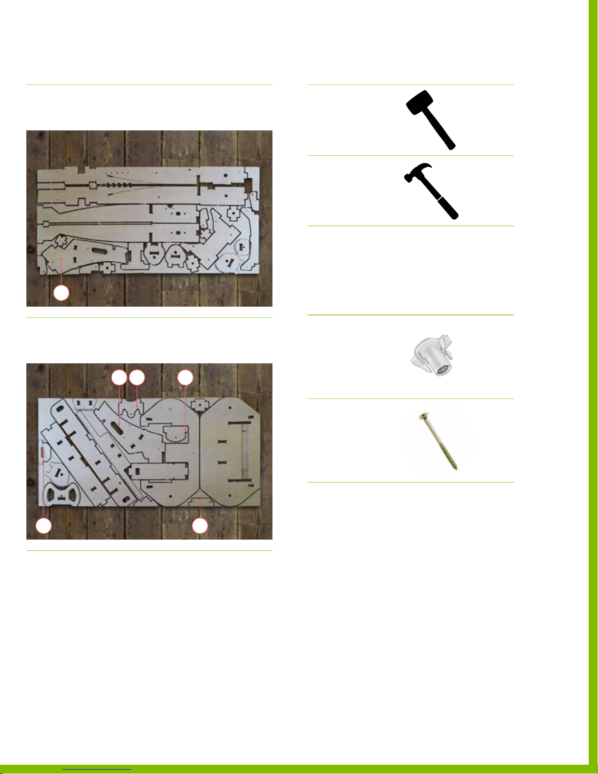
Plywood sheet reference
DESCRIPTION REFERENCE
Recommended tools
DESCRIPTION REFERENCE
Sheet 1
3/4” Plywood Sheet
13
Sheet 2
3/4” Plywood Sheet
‒ Parts 13
Dead blow hammer
or mallet
Hammer
Required hardware
№ DESCRIPTION REFERENCE
‒ Parts 14‑18
2 Small Tee Nut
Zinc Plated, 5/16”‑18
PN 12 510
15 1814
12 Spax Screw
#8, 1‑1/2” L
PN 12 519
1716
150718 PLYFL Y rev A_Steer fixed | A ug u s t 7 , 2 01 5 5: 0 6 PM
PlyFly Go‑Kart Instruction Guide • 2015 Release
19
Page 24
Required wooden parts
DESCRIPTION REFERENCE
Part 13
Steering Column Left
PLYWOOD SHEET 1
Assembling the steering column
INSTRUCTIONS
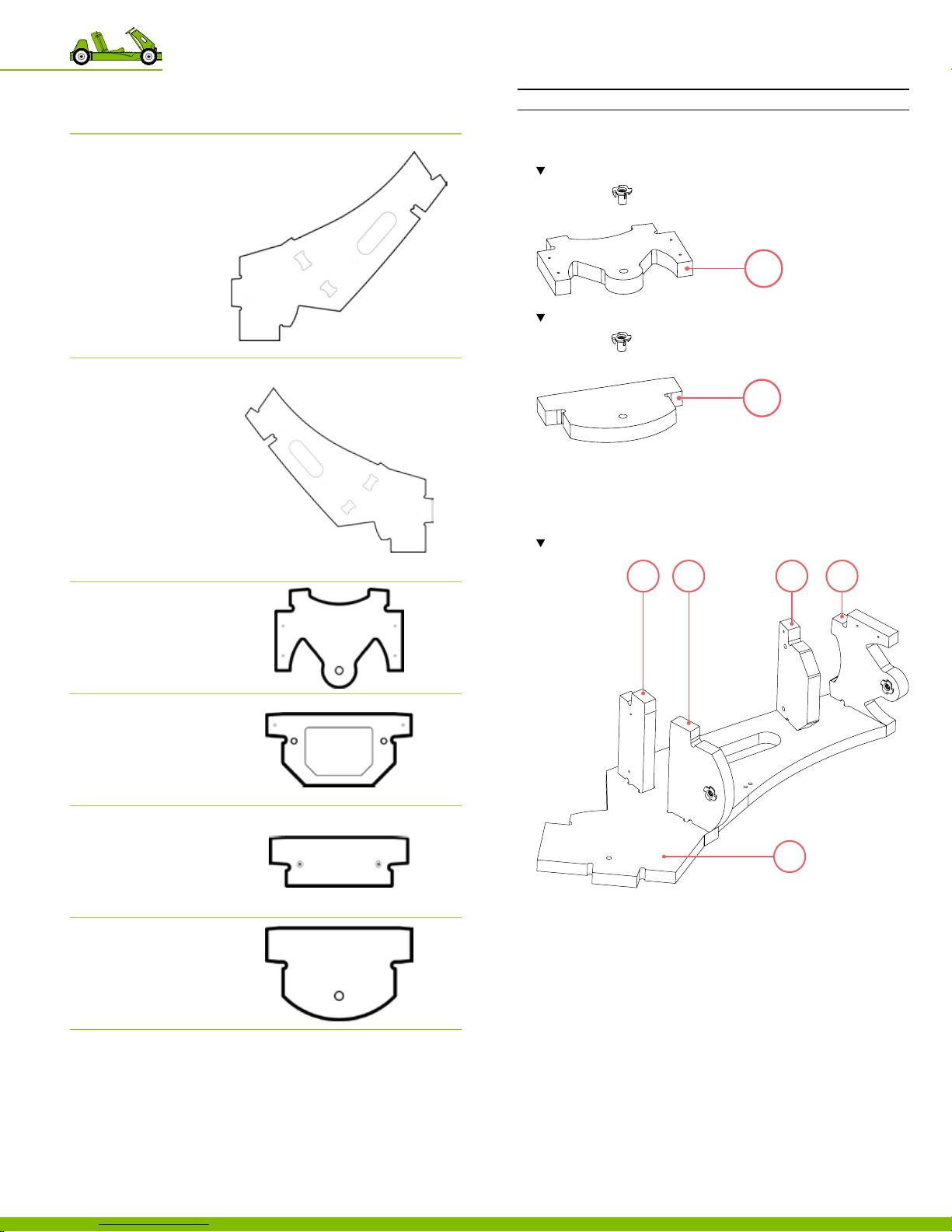
1. Press t ee nuts into parts 15 & 18
Note the orientation of par t 15.
15
Note the orientation of par t 18.
18
Part 14
Steering Column Right
PLYWOOD SHEET 2
Part 15
Steering Column Top
PLYWOOD SHEET 2
Part 16
Steering Column Phone
Mount
PLYWOOD SHEET 2
Part 17
Steering Column Bracket
PLYWOOD SHEET 2
Part 18
Steering Pinion Mount
PLYWOOD SHEET 2
2. Using a hammer, tap the t ee nut until the top is ush with
the wooden part.
3. Using a mallet, tap parts 15 , 16, 17, & 18 into the
corresponding slots on part 13.
Note the location and orientation of each part.
17 18 16 15
13
4. Align part 14 to the assembly so that the part mirrors
part 13 exactly.
5. Using a mallet, tap part 14 into the tab connections.
6. Secure the parts using screws on each part.
‒ Use 1 screw per part, per side.
‒ Total of 4 locations, 4 screws.
7. Secure the parts on the opposite side, turn the assembly
on its side, and then screw in each part.
‒ Use 1 screw per part, per side.
‒ Total of 4 locations, 4 screws.
150718 PLYFL Y rev A_Steer fixed | A ug u s t 7 , 2 01 5 5: 0 6 PM
6 Fixed Steering Column Assembly
20
Page 25
SteeringSpindle
7
Assemblies
Introduction
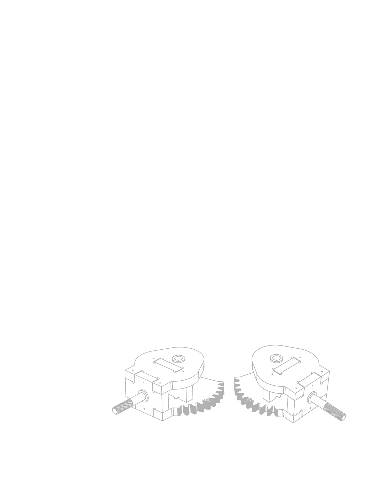
Before beginning this assembly, be sure to chisel
out and sand parts 1‑8. These 8 components
are required to fully assemble 2 steering spindle.
Each assembly contains 4 parts.
150718 PL YFLY rev A_Steer spindle | A ug u s t 7, 2 01 5 5 : 06 P M
21
Page 26
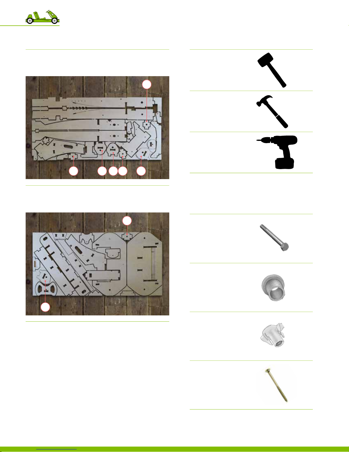
Plywood sheet reference
DESCRIPTION REFERENCE
Sheet 1
3/4” Plywood Sheet
‒ Part 1
‒ Parts 3‑4
‒ Parts 6‑8
Recommended tools
DESCRIPTION REFERENCE
Dead blow hammer
or mallet
3
Hammer
Electric Driver
61874
Sheet 2
3/4” Plywood Sheet
5
‒ Part 2
‒ Part 5
Required hardware
№ DESCRIPTION REFERENCE
2
2 Shor t Hex Bolt
Grade 5, 5/8”‑11, 6.5” L
PN 12503
6 Large Metal Bushing
Flanged, 3/4” OD, 5/8” ID
PN 12 50 4
2 Small Tee Nut
Zinc Plated, 5/16”‑18
PN 12 510
150718 PL YFLY rev A_Steer spindle | A ug u s t 7, 2 01 5 5 : 06 P M
7 Steering Spindle Assemblies
22
20 Spax Screw
#8, 1‑1/2” L
PN 12 519
Page 27
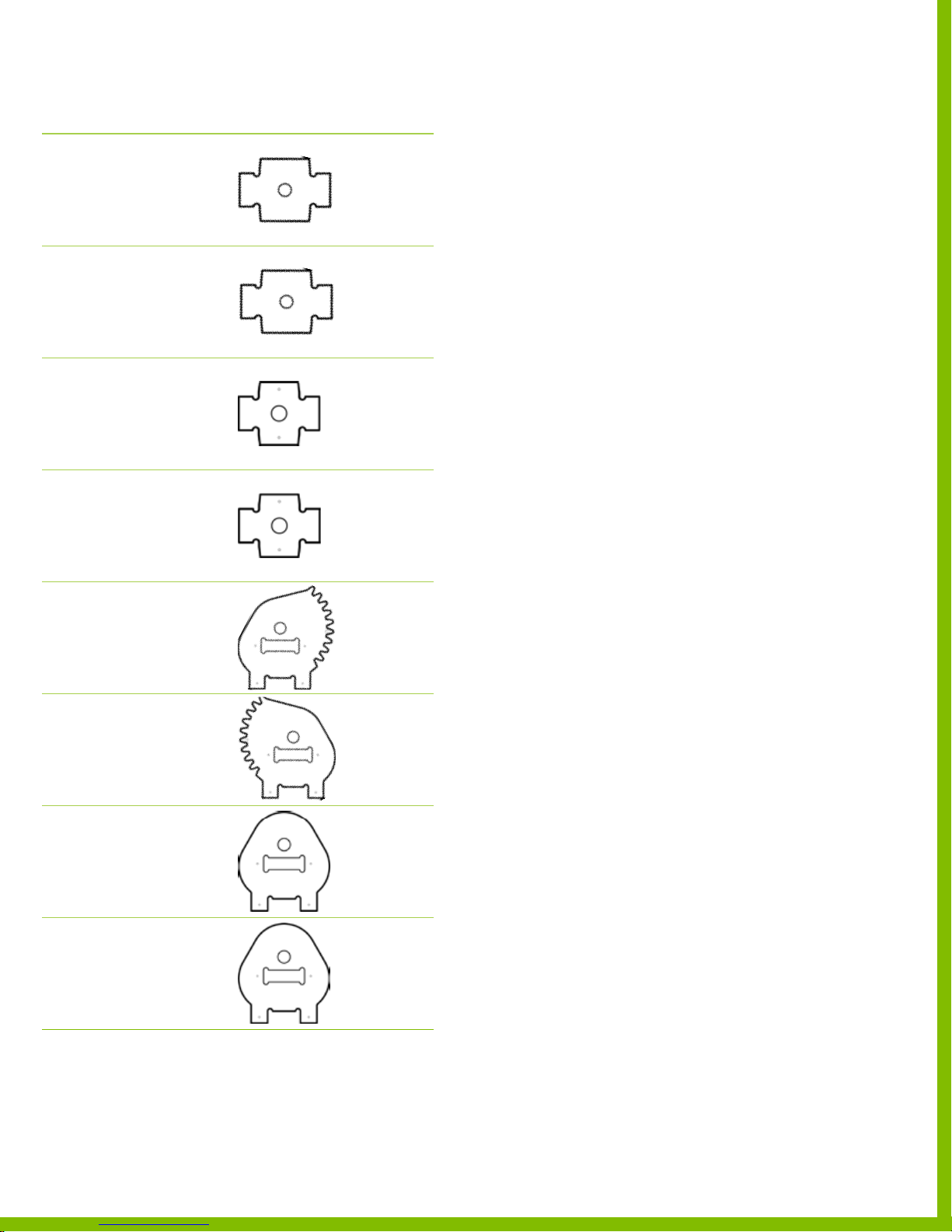
Required wooden parts
DESCRIPTION REFERENCE
Part 1
Steering Spindle Outer Spacer
PLYWOOD SHEET 1
Part 2
Steering Spindle Outer Spacer
PLYWOOD SHEET 2
Part 3
Steering Spindle Inner Spacer
PLYWOOD SHEET 1
Part 4
Steering Spindle Inner Spacer
PLYWOOD SHEET 1
Part 5
Steering Spindle Bottom Left
PLYWOOD SHEET 2
Part 6
Steering Spindle Bottom Right
PLYWOOD SHEET 1
Part 7
Steering Spindle Top
PLYWOOD SHEET 1
Part 8
Steering Spindle Top
PLYWOOD SHEET 1
150718 PL YFLY rev A_Steer spindle | A ug u s t 7, 2 01 5 5 : 06 P M
PlyFly Go‑Kart Instruction Guide • 2015 Release
23
Page 28
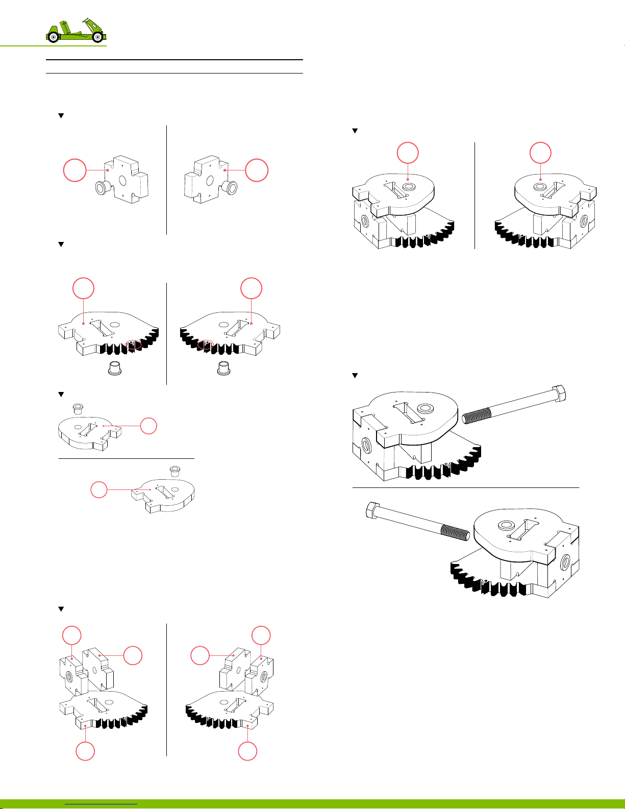
Assembling the left & right steering spindles
INSTRUCTIONS
1. Press bushings into parts 1‑2, 5‑6, & 7‑8
Note the orientation of par t 1 & 2.
1
Note Be sure to insert the bushing on the opposite side of the alignment mark.
Parts 5 & 6 a re left and a right side biased.
2
5 6
Note the location of the bushings.
7. Using a mallet, cap the parts 1, 3, 5 with part 7.
8. Using a mallet, cap the parts 2, 4, 6 with part 8.
Note the location of the bushings.
87
9. Secure the parts using screws on each part.
‒ Use 2 screws on part 5
‒ Use 2 screws on part 6
‒ Use 4 screws on part 7
‒ Use 4 screws on part 8
‒ Total 20 locations, 20 screws.
10. Using a hammer, insert the 5/8” long bolt into each
steering spindle assembly.
Note the location of the bushings
7
8
2. Using a hammer, tap the bushings until the top is ush
with the wooden part.
3. Using a mallet, tap parts 1 into the outer slot on part 5.
4. Using a mallet, tap parts 2 into the outer slot on part 6.
5. Using a mallet, tap parts 3 into the inner slot on part 5.
6. Using a mallet, tap parts 4 into the inner slot on part 6.
Note the location of the bushings. The bushing should face ou twards.
Try to ensure 90°
1
3
4
2
150718 PL YFLY rev A_Steer spindle | A ug u s t 7, 2 01 5 5 : 06 P M
5
7 Steering Spindle Assemblies
24
6
Page 29
8
Pedal Assemblies
Introduction
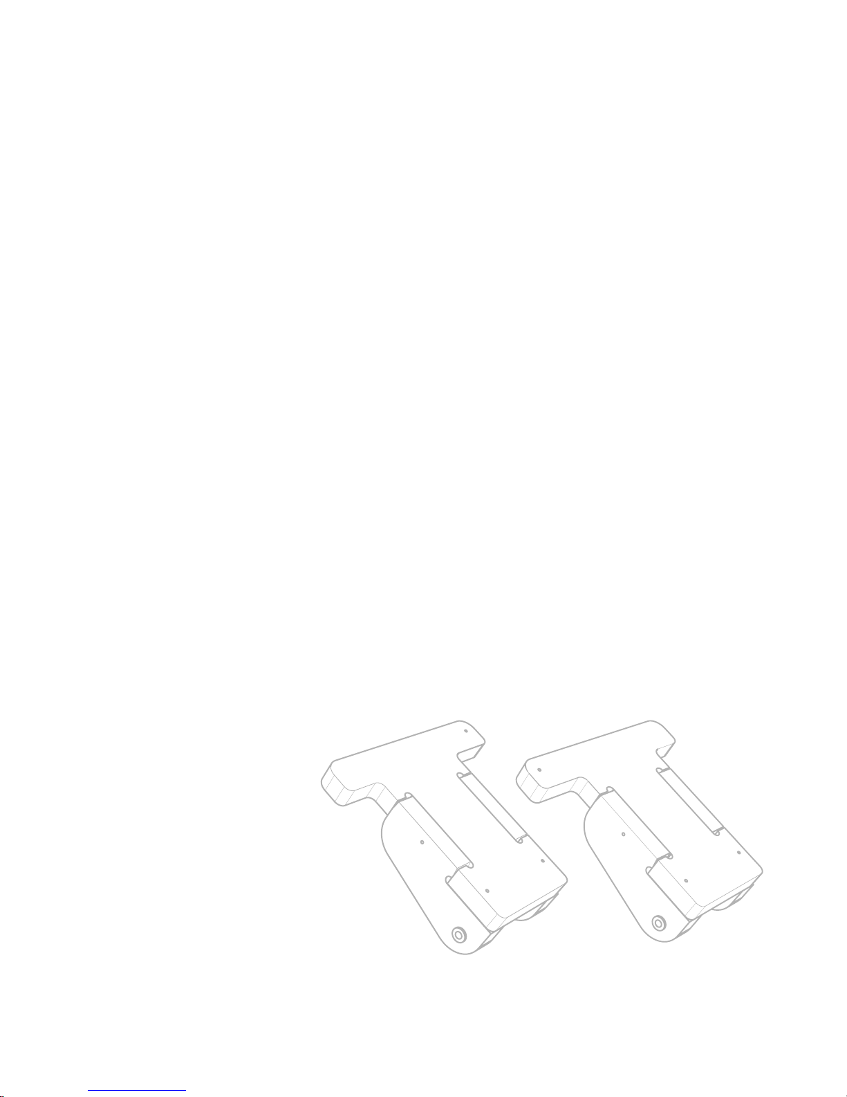
Before beginning this assembly, be sure to chisel out and sand
parts 34 ‑ 39. These 6 components are required to fully assemble
the go‑kart gas and brake pedals. Each assembly contains 3 parts.
150718 PLYFL Y rev A_Pedal | Au g us t 7, 2 01 5 5: 0 6 P M
25
Page 30
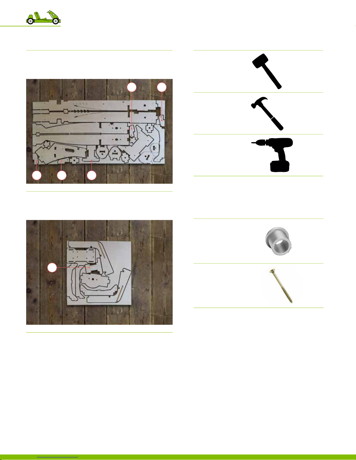
Plywood sheet reference
DESCRIPTION REFERENCE
Recommended tools
DESCRIPTION REFERENCE
Sheet 1
3/4” Plywood Sheet
3736
Sheet 3
3/4” Plywood Sheet
‒ Parts 34
‒ Parts 36‑39
Dead blow hammer
or mallet
38 39
Hammer
Electric Driver
34
‒ Parts 35
Required hardware
№ DESCRIPTION REFERENCE
35
4 Plastic Bushing
Flanged, 1/4” ID, 3/8” OD
PN 12 50 9
8 Spax Screw
#8, 1‑1/2” L
PN 12 519
150718 PLYFL Y rev A_Pedal | Au g us t 7, 2 01 5 5: 0 6 P M
8 Pedal Assemblies
26
Page 31
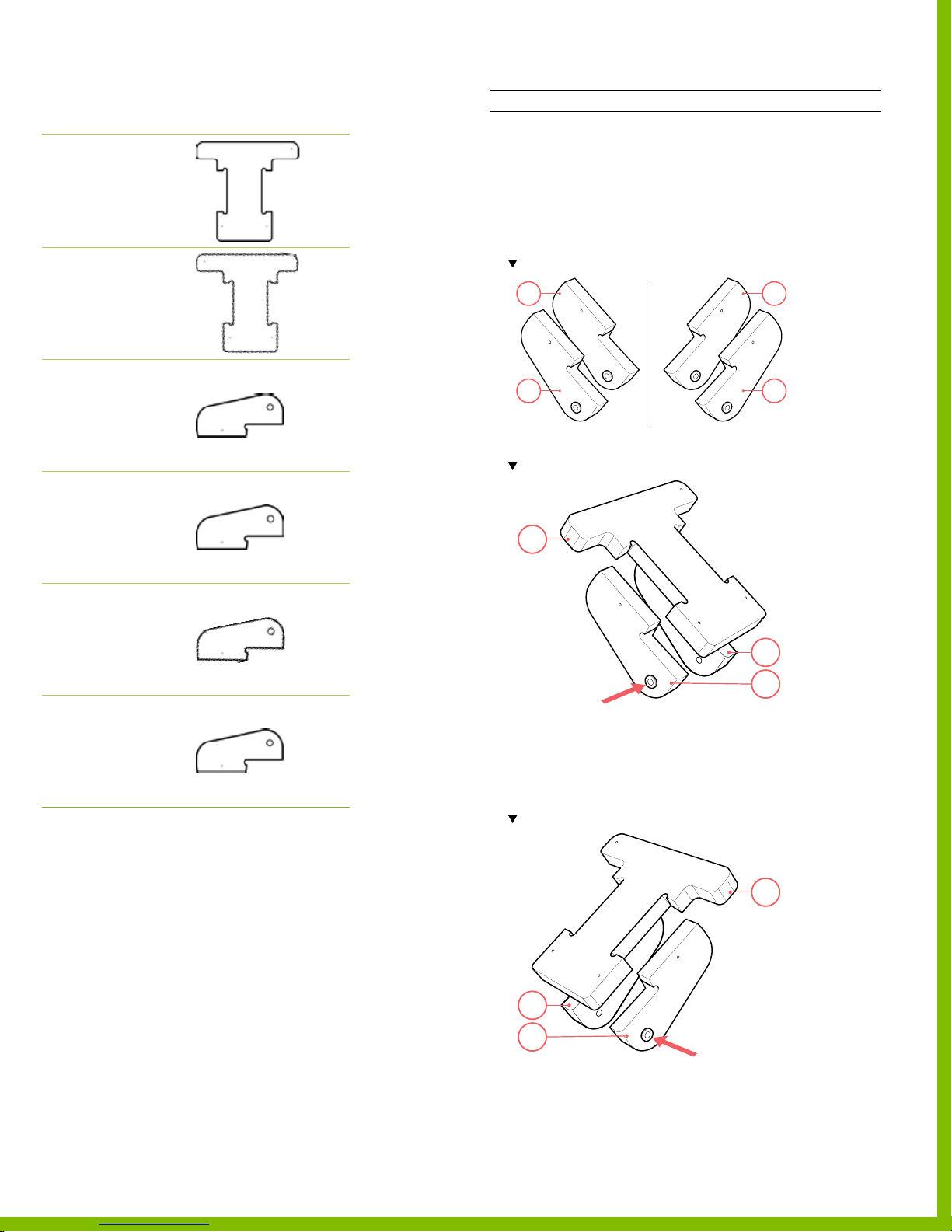
Required wooden parts
DESCRIPTION REFERENCE
Part 34
Brake Pedal
PLYWOOD SHEET 1
Part 35
Gas Pedal
PLYWOOD SHEET 3
Assembling the gas & the brake pedals
INSTRUCTIONS
1. Insert and hammer into place the bushings into parts
‒ Part 36
‒ Par t 37
‒ Part 38
‒ Part 39
Note the part orientat ion. The n al 2 assemb lie s are mirror ima ges of each other.
38
39
Part 36
Pedal Side
PLYWOOD SHEET 1
Part 37
Pedal Side
PLYWOOD SHEET 1
Part 38
Pedal Side
PLYWOOD SHEET 1
Part 39
Pedal Side
PLYWOOD SHEET 1
36
37
2. Using a mallet, tap parts 36 & 37 into the slots on part 34.
Note par t location and orientation of par ts 36-37. Be sure to squa re the parts.
34
36
37
3. Secure parts 34, 36 & 37 using screws.
‒ Use 2 screws per part & per side.
‒ Total of 4 locations, 4 screws.
4. Repeat step 2 using parts 35, 38 & 39.
Note par t location and orientation of par ts 36-37. Be sure to squa re the parts.
150718 PLYFL Y rev A_Pedal | Au g us t 7, 2 01 5 5: 0 6 P M
38
39
5. Secure parts 35, 38 & 39 using screws.
‒ Use 2 screws per part & per side.
‒ Total of 4 locations, 4 screws.
PlyFly Go‑Kart Instruction Guide • 2015 Release
35
27
Page 32
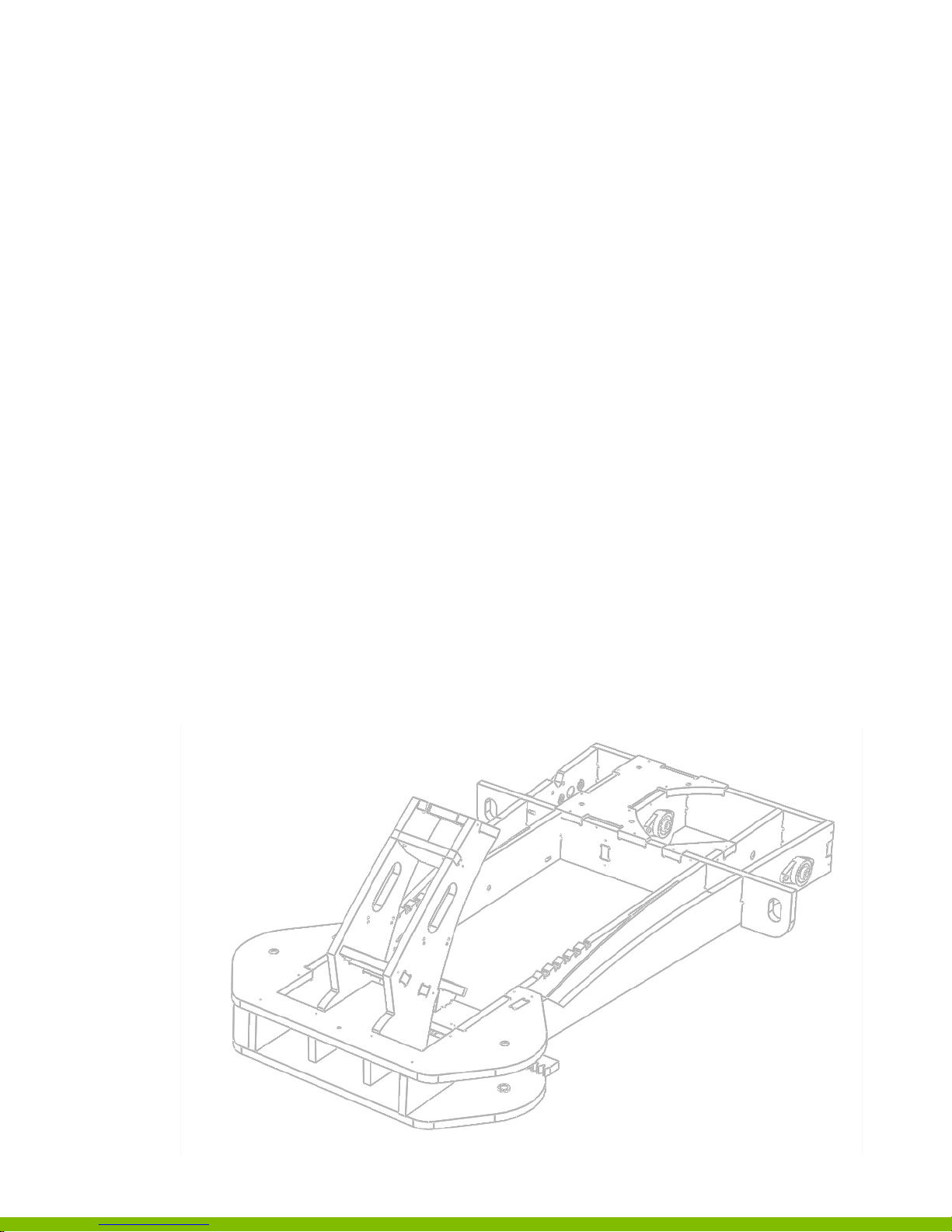
9
Frame Assembly
Introduction
Before beginning this assembly, be sure to chisel
out and sand parts 40‑55. These 11 components
and assemblies1‑3 are required to fully assemble
the go‑kart frame.
150718 PLYFL Y rev A_Frame | A ug u st 7 , 2 0 15 5: 0 6 P M
28
Page 33
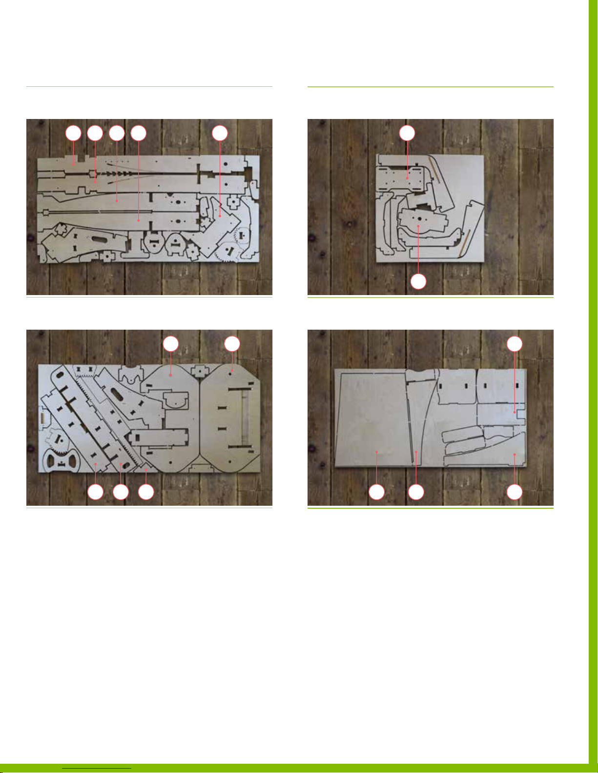
Plywood sheet reference
DESCRIPTION REFERENCE
DESCRIPTION REFERENCE
Sheet 1
3/4” Plywood Sheet
Sheet 2
3/4” Plywood Sheet
‒ Parts 40‑43
‒ Part 49
‒ Parts 44‑46
‒ Part 48
‒ Part 52
4941 40 43 42
45 44
Sheet 4
1/4” Plywood Sheet
Sheet 4
1/4” Plywood Sheet
‒ Part 47
‒ Part 50
50
47
‒ Part 51
‒ Part 53‑54
‒ Part 55
55
46 5248
150718 PLYFL Y rev A_Frame | A ug u st 7 , 2 0 15 5: 0 6 P M
51
53 54
PlyFly Go‑Kart Instruction Guide • 2015 Release
29
Page 34
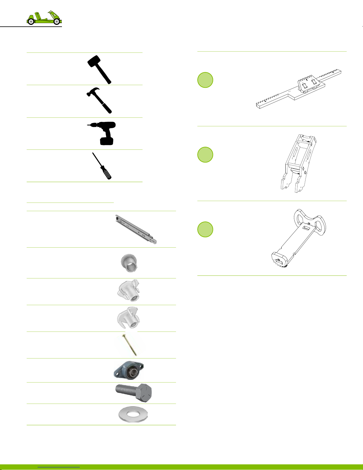
Recommended tools
DESCRIPTION REFERENCE
Dead blow Hammer
or mallet
Hammer
Electric Driver
Required assemblies
DESCRIPTION REFERENCE
1
Steering rack
Assembly
Parts 9‑12
2
Screwdriver
Required hardware
№ DESCRIPTION
1 Drawer Slide
Hardware included, 10” L
PN 12 50 8
Large Metal Bushing
Flanged, 3/4” OD, 5/8” ID
SINGLE WHEEL KIT PN 125 0 4
5
4 LIVE A XLE KIT P N 12 50 4
10 Large Tee Nut
Zinc Plated, 3/8”‑16
PN 12 54 5
10 Small Tee Nut
Zinc Plated, 5/16”‑18
PN 12 510
Fixed steering column
Assembly
Pa r t s 13‑18
REFERENCE
3
Steering column
Assembly
Par ts 19‑21
30 Spax Screw
#8, 1‑1/2” L
PN 12 519
3 VXB Mounted Bearing
5/8” ID
PN 12 521
4 Hex head cap screw
5/16”‑18, 1.25 L
PN 12 54 3
4 Flat Washer
5/16” ID, 7/8” OD
PN 12 516
9 Frame Assembly
30
150718 PLYFL Y rev A_Frame | A ug u st 7 , 2 0 15 5: 0 6 P M
Page 35
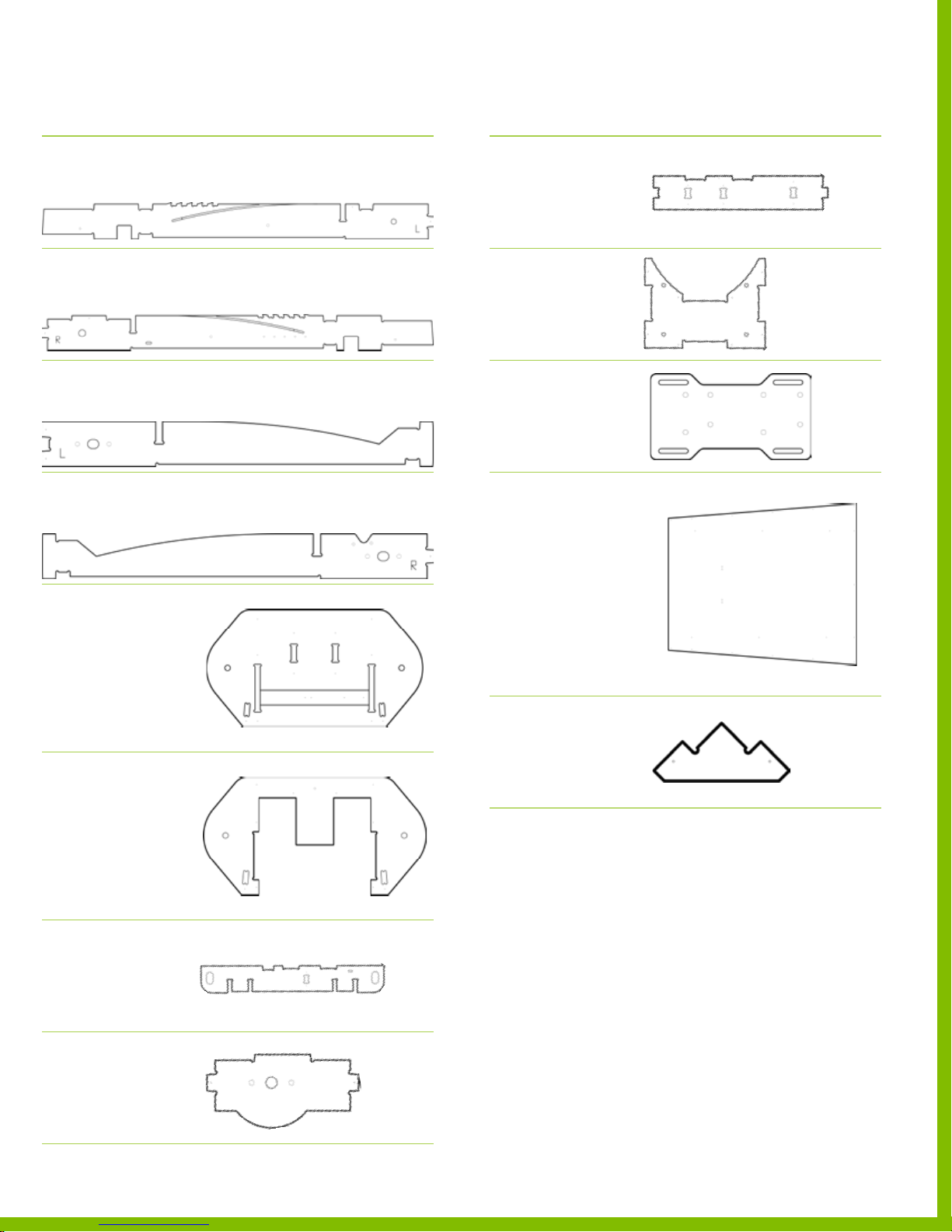
Required wooden parts
DESCRIPTION REFERENCE
Part 40
Frame Rail Inner Lef t
PLYWOOD SHEET 1
Part 41
Frame Rail Inner Right
PLYWOOD SHEET 1
Part 42
Frame Rail Outer Left
PLYWOOD SHEET 1
Part 43
Frame Rail Outer Right
PLYWOOD SHEET 1
DESCRIPTION REFERENCE
Part 48
Frame Rail Rear
PLYWOOD SHEET 2
Part 49
Frame Rail Engine Mount
PLYWOOD SHEET 1
Part 50
Engine Mounting Plate
PLYWOOD SHEET 3
Part 44
Front‑end Bottom
PLYWOOD SHEET 2
Part 45
Fr o nt‑ e n d Top
PLYWOOD SHEET 2
Part 46
Frame Rail Bracket
PLYWOOD SHEET 2
Part 51
Floor Panel
PLYWOOD SHEET 4
Part 52
Frame Gusset
PLYWOOD SHEET 2
Part 47
Sprocket Guard
PLYWOOD SHEET 3
150718 PLYFL Y rev A_Frame | A ug u st 7 , 2 0 15 5: 0 6 P M
PlyFly Go‑Kart Instruction Guide • 2015 Release
31
Page 36
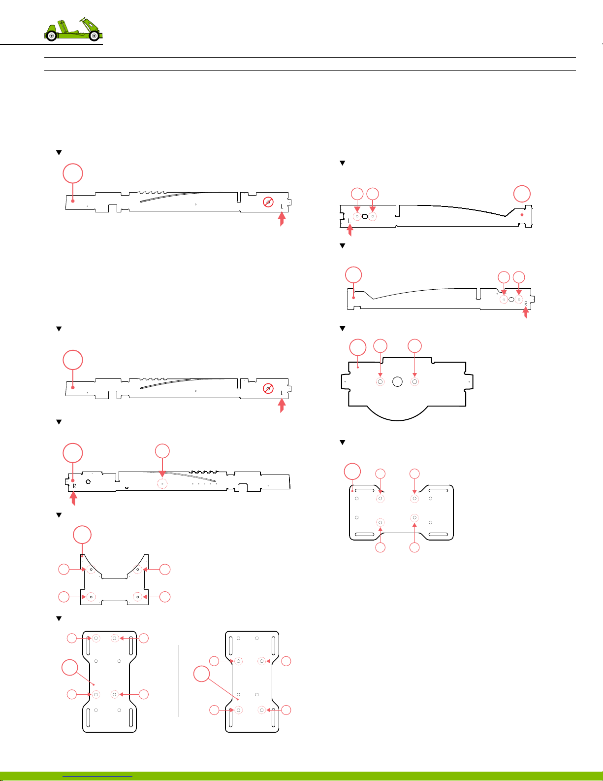
Assembling the frame
INSTRUCTIONS
1. To begin this assembly
‒ Start at Step 2 if you have a
‒ Start at Step 4 if you have a
2. Press the bushing into part 40.
Note the location of the bushing on par t 40. Install on the opposite side of the L.
40
SINGLE WHEEL KIT.
LIVE A XLE KIT.
5. Press the large tee nuts into
‒ Part 42‑43
‒ Par t 47
‒ Part 50; on the opposite side of the small tee nut
installation.
Note the location of 2 large tee nuts on par t 42. Install on the same side of
the L.
3. Using a hammer, tap the bushing until the top is ush with
the wooden part.
4. Press the small tee nuts into
‒ Pa rt 40‑41
‒ Part 49
‒ Part 50; be sure to follow installation pattern for the
correct engine model.
Note the location of the small tee nut on part 40; install on the same side of
the L.
40
Note the location of the small tee nut on part 41. Install on the same side of
the L.
41
1
1 2
Note the location of 2 large tee nuts on par t 43. Install on the same side of
the L.
43
Note the location of 2 large tee nust on part 47.
1 2
47
Note the location of 4 large tee nuts on par t 50. Install on opposing side of the
small tee nut installion on part 50.
50
1 2
42
1 2
Note the location of 4 small tee nuts on par t 49.
49
32
1
2
Note the location of 4 small tee nuts on par t 50
1
50
2.5 HP
2
9 Frame Assembly
3
4
3
50
4
3 4
6. Using a hammer, tap the tee nuts until the top is ush with
the wooden part.
‒ Parts 41‑43, 47, 49 & 50.
‒ Use 20 tee nuts; 10 small and 10 large.
150718 PLYFL Y rev A_Frame | A ug u st 7 , 2 0 15 5: 0 6 P M
‒ Total of 20 locations.
7. Screw in the llester head machine screws into the
tee nuts located parts 40 & 41.
1
4.0 HP
2
3
4
‒ Tighten down until it stands ush with 3/8” protrusion.
Page 37
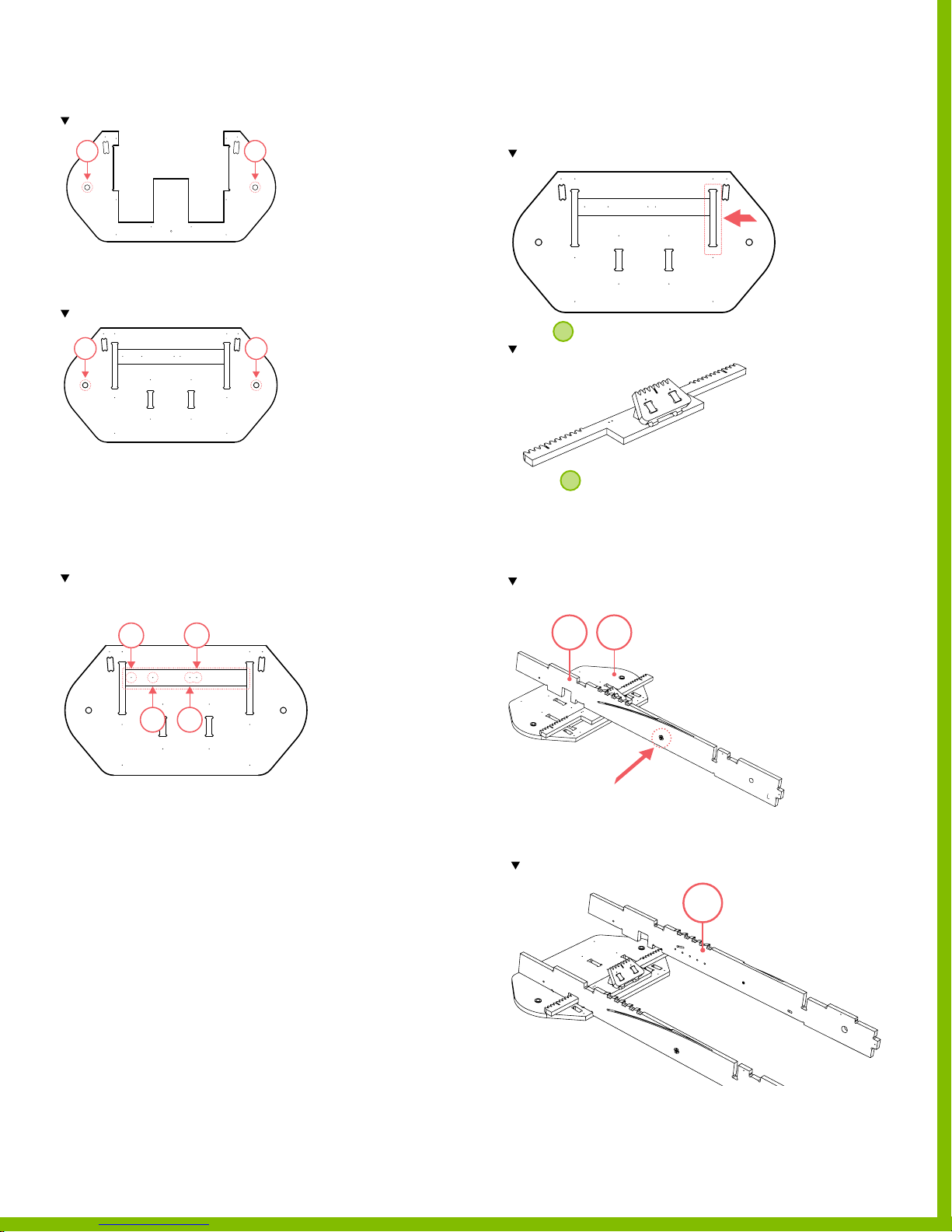
8. Press 2 bushings into part 45.
Note the location of the bushing on par t 45
1 2
9. Using a hammer, tap the bushings until the top is ush
with the wooden part.
10. Press 2 bushings into part 44.
Note the location of the bushings on par t 44
1 2
11. Using a hammer, tap the bushings until the top is ush
with the wooden part.
12. Install the drawer slide on part 44, by extending the slide
to its furthest extended position.
13. Align the 4 screw holes on the drawer slide with holes
found in the recess on part 44.
Note the location and pos iti on of the mou nting hol es. Th e drawer slide shou ld t
into the recessed pocket on par t 44.
16. Extend the drawer slide until the last two holes on the
drawer slide are accessible from the underside through
the slot located on part 44.
Note the location of the referenced slot on part 44.
Mount
1
to the drawer slide.
Note the cor rect assembly
17. Secure 1 using screws.
‒ Use the remaining screws included in the
Drawer Slide Kit.
18. Using a mallet, tap part 40 into the tab connections on
the left side of part 44.
Note the location and orientation of the tee nut on pa rt 40;
the letter L should face inwa rd to the centerline of the go-ka rt.
1
2
3 4
14. Secure the drawer slide to part 44 using screws.
‒ Use a screwdriver and the screws provided in the
Slide Drawer Kit.
‒ Use 4 screws
‒ Total 4 locations
15. Test the drawer slide t by moving the
slide back and forth.
‒ Be sure there are no interferences between any
screw head and the slide.
44
40
19. Using a mallet, tap part 41 into the tab connections on the
left side of part 44.
Note the letter L should face part 41, away from the centerline of the go-kart.
41
150718 PLYFL Y rev A_Frame | A ug u st 7 , 2 0 15 5: 0 6 P M
PlyFly Go‑Kart Instruction Guide • 2015 Release
33
Page 38
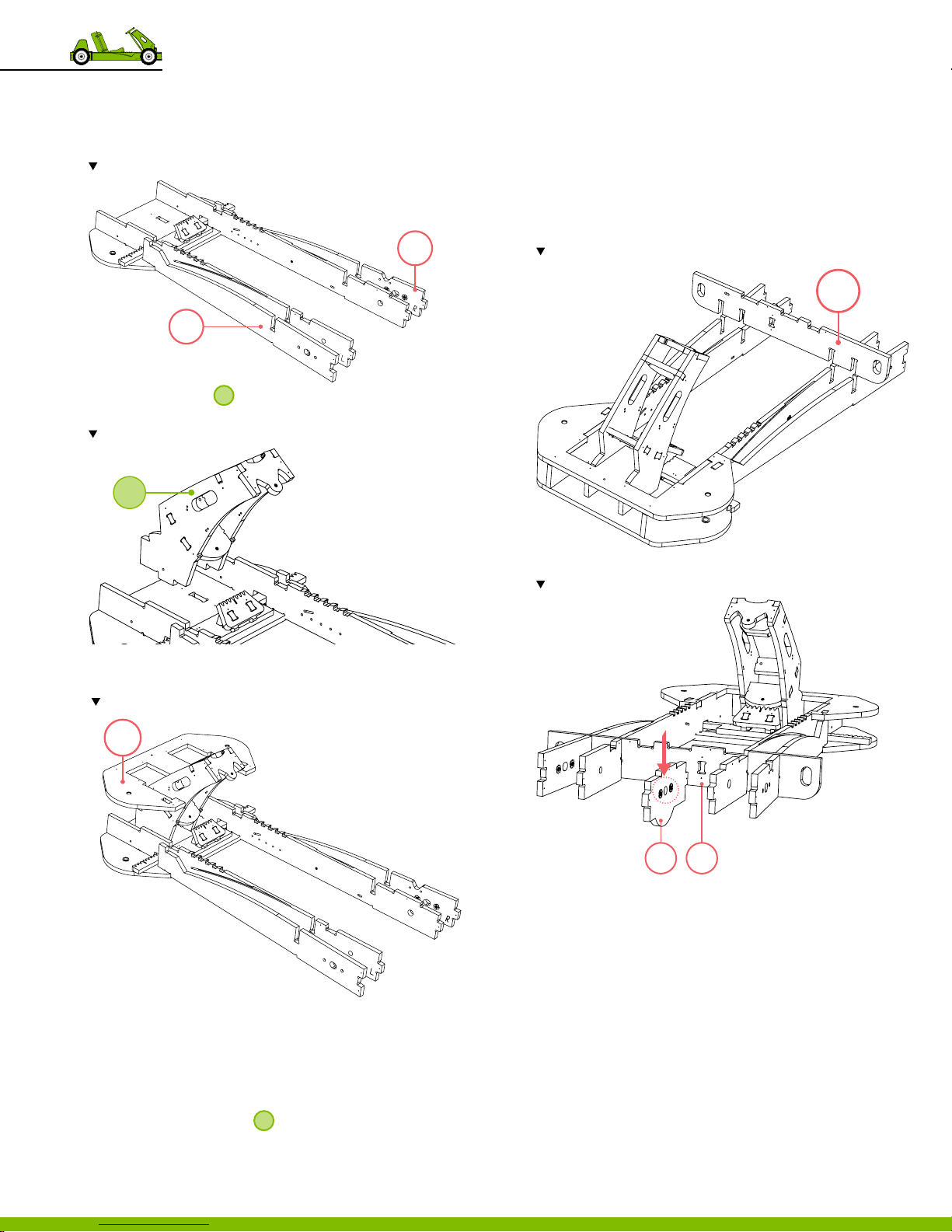
20. Repeat steps 18 and 19 using
‒ Part 42
‒ Part 43
Note the let ter L should face part 41, away from the centerline of the go-kar t.
42
43
25. Secure part 44 to the assembly using screws.
‒ There is a purposeful gap in alignment to allow part 51
to sit ush with the assembly.
‒ Use 12 screws.
‒ Total of 12 locations.
26. Flip the assembly right side up again.
27. Using a mallet, tap part 46 into place.
Note the orientation and posi tion the tabs on part 46.
46
21. Using a mallet, tap
2
into the tab connections in the
center of part 44.
Note the orientation and location of the assembly.
2
22. Using a mallet, tap part 45 slots into the tab connections
of go‑kart front‑end (parts 40‑43).
Note the correct orientation for part 45; the bushings face(down) par t 44.
45
28. Using a mallet, tap part 47 into the center slot of part 46.
Note the orientation and posi tion of part 47.
23. Secure part 45 using screws.
‒ Use 12 screws.
‒ Total of 12 locations.
24. Flip the assembly over and using a mallet, tap any
unseated tabs into place.
2
‒ It is best to do this with
hanging o the edge of
a table or saw horses.
9 Frame Assembly
34
47 46
29. Secure parts 46 to part 47 using screws.
‒ Use 2 screws.
‒ Total of 2 locations.
150718 PLYFL Y rev A_Frame | A ug u st 7 , 2 0 15 5: 0 6 P M
Page 39
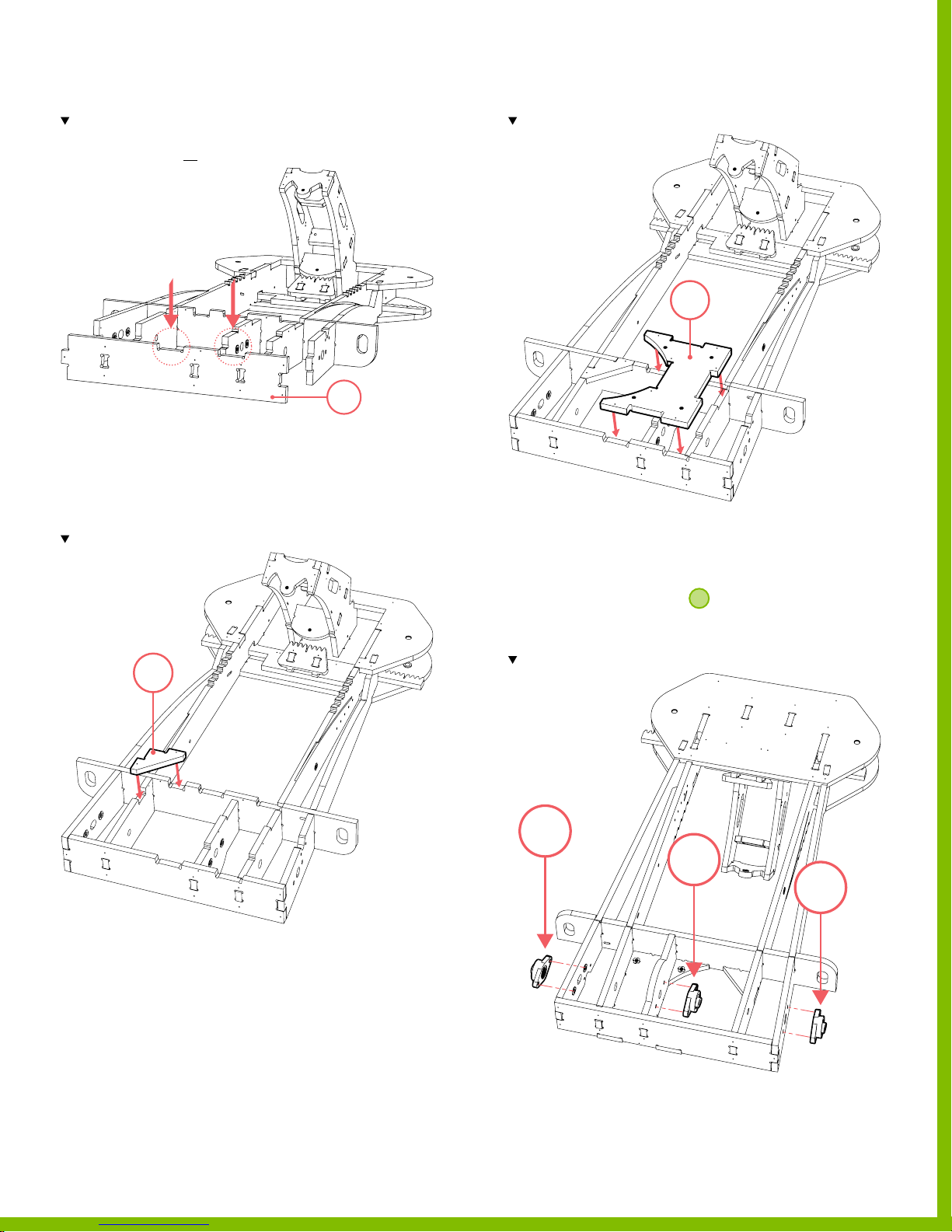
30. Using a mallet, tap part 48 into the 5 connection tabs.
Note the orientation and posi tion of cut-out tabs, it should face upward.
To ensure alig nment of all 5 tab connections; prior to using a mallet, tack 1 corner of
part 48 with a screw that is not tightened down all the way.
48
31. Secure part 48 to the assembly using screws on the
rear face, left and right side faces.
‒ Use 12 screws.
‒ Total of 12 locations.
32. Using a mallet, tap part 52 into place.
Note the orientation and posi tion of part 52.
52
34. Using a mallet, tap part 49 into place.
Note the orientation and posi tion of part 49.
49
35. Secure part 49 using screws.
‒ Use 8 screws.
‒ Total of 8 locations.
2
36. Flip assembly over allowing
saw horses.
37. Install the 3 mounted bearings
Note the orientation, location and position of each mounted bearing.
to hang o table or
33. Secure part 52 using screws.
‒ Use 2 screws.
‒ Total of 2 locations.
150718 PLYFL Y rev A_Frame | A ug u st 7 , 2 0 15 5: 0 6 P M
1
2
3
PlyFly Go‑Kart Instruction Guide • 2015 Release
35
Page 40
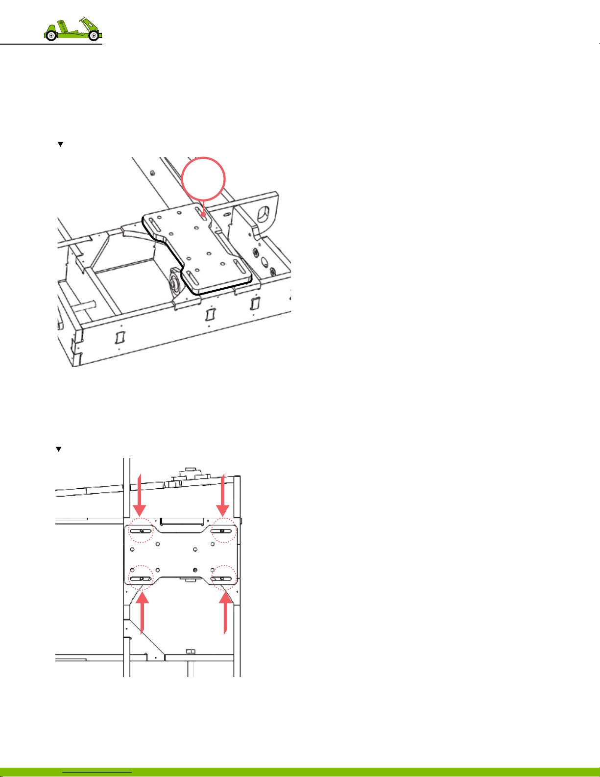
38. Using a mallet, tap part 51 into place.
39. Secure part 51 to the assembly using 21 screws.
‒ Total of 21 locations, 21 screws.
40. Flip assembly right side up.
41. Lay part 50, with the small tee nuts facing upwards, into
place.
Note the orientation and position of tee nut pattern on part 50.
50
42. Secure part 50 to the assembly using washers &
hex head cap screw.
‒ Use 4 washers
‒ Use 4 hex head cap screw.
‒ Total 4 locations.
Note the orientation and posi tion of the hex hed bolts; tee-nuts should face up.
150718 PLYFL Y rev A_Frame | A ug u st 7 , 2 0 15 5: 0 6 P M
9 Frame Assembly
36
Page 41
Putting the go-kart
10
together
Introduction
Before beginning this nal assembly, be sure to have
assemblies 1‑7 completed. These 8 assemblies are required to
fully assemble the go‑kart.
This chapter contains 10 individual procedural parts to
successfully complete the full go‑kart assembly.
150718 PLYFL Y rev A_GoKart | A ug u st 7, 20 1 5 5:0 8 PM
37
Page 42
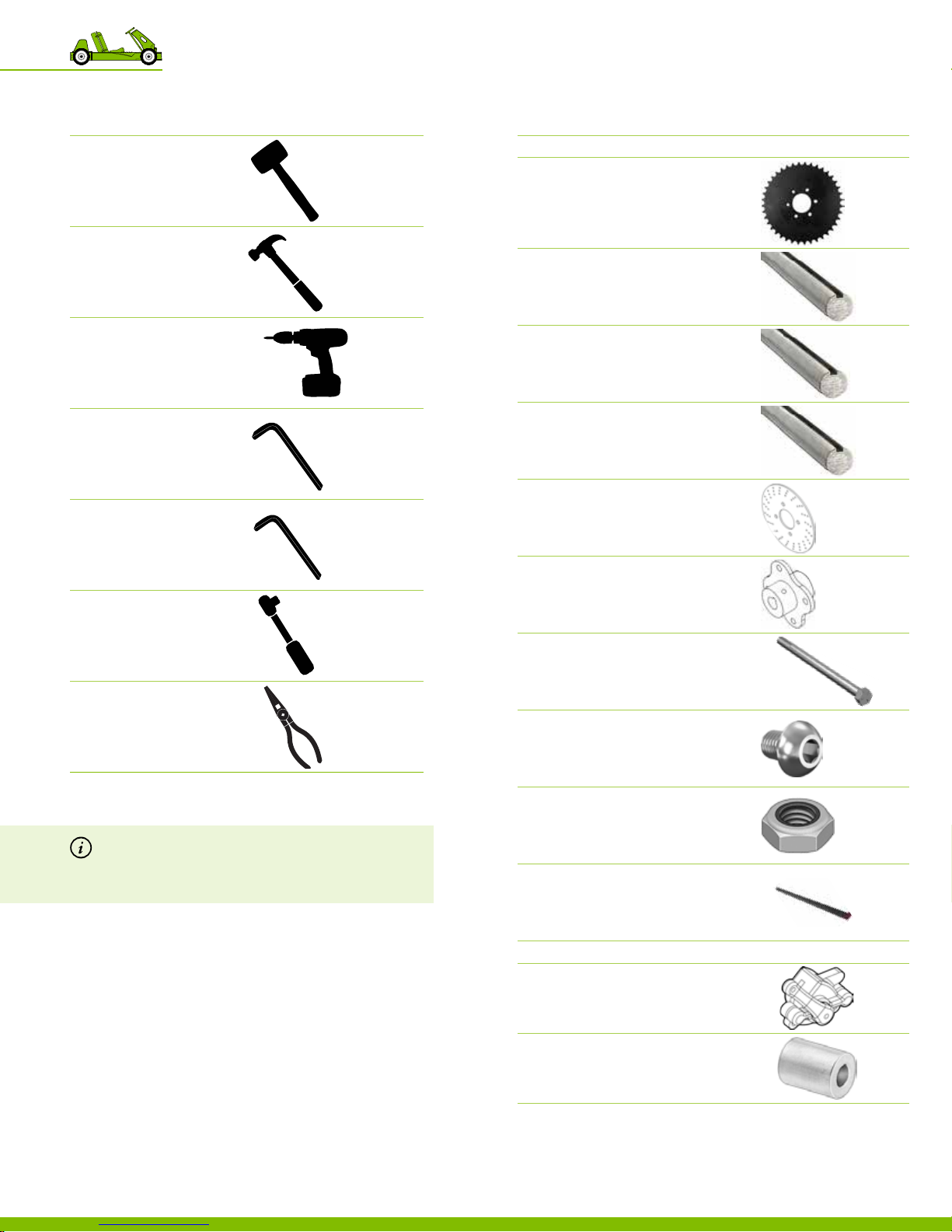
Overview of the recommended tools
DESCRIPTION REFERENCE
Overview of the required hardware
№ DESCRIPTION REFERENCE
PART 1
Dead blow Hammer
or mallet
Hammer
Electric Driver
Allen Wrench
or ratcheting Allen wrench
Metric Allen Wrench
included with mounted bearing
1 Sprocket
5/8” bore diameter
60 Tooth, #35 Chain
PN 12 52 2
1 Drive Shaft
Steel, Keyed, 5/8” D, 18” L
SINGLE WHEEL KIT PN 125 8 0
1 Drive Shaft
Steel, Keyed, 5/8” D, 33” L
LIVE A XLE KIT – 10” WHEELS PN 125 81
1 Drive Shaft
Steel, Keyed, 5/8” D, 36” L
LIVE A XLE KIT – 12” WHEELS PN 12 5 82
1 Brake Disc
PN 12 53 2
1 Brake Disc Hub
PN 12 53 3
Socket Wrench
Needle Nose Pliers
Note There are 2 types of button socket head cap screws
provided in every kit. They appear to be similar in
size but are not. The easiest way to dierentiate the
2 sizes, is by the number of screws provided.
1 Long Hex Bolt
Axle Grade 5, 5/8”‑11, 11” L
SINGLE WHEEL KIT PN 12 5 02
4 Button Socket Head Cap Screw
Zinc Plated, Steel, 5/16”‑24, 1/2” L
TOTAL OF 4 PROVID ED P N 125 59
4 Thin Nut
Grade 5, 5/16”‑24
PN 12 52 0
1 Key
3/16” square, 1”L
PN 12 53 9
PART 2
1 Brake Caliper
PN 12 53 1
1 Short Aluminum Spacer
1/2” OD, 1/4” ID, 7/8” L
PN 12 547
150718 PLYFL Y rev A_GoKart | A ug u st 7, 20 1 5 5:0 8 PM
10 Putting the go‑kart together
38
Page 43
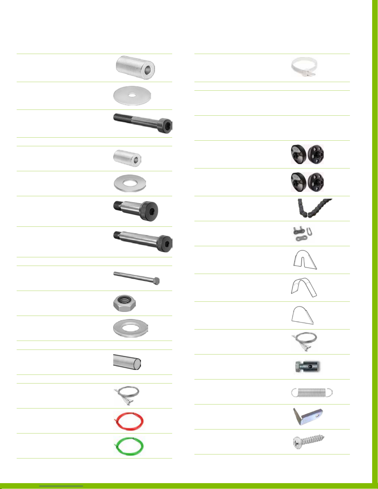
Overview of the required hardware
№ DESCRIPTION REFERENCE
Overview of the required hardware
№ DESCRIPTION REFERENCE
1 Long Aluminum Spacer
1/2” OD, 1/4” ID, 1‑1/16” L
PN 12 54 8
2 Oversized Flat Washer
Zinc, M6
PN 12 54 9
2 Socket Head Cap Screw
Black oxide, M6, 55mm L
PN 12 55 0
PART 3
1 Nylon Spacer
3/4” OD, 3/8” ID, 1‑1/4” L
PN 12 54 6
4 Flat Washer
5/16” ID, 7/8” OD
PN 12 516
Shor t Shoulder Screw
1
3/8” D, 1” L, 5/16”‑18
PN 12 513
Long Shoulder Screw
1
3/8” D, 2‑1/4” L, 5/16”‑18
PN 12514
PART 4
2 Short Hex Bolt
Grade 5, 5/8”‑11, 6.5” L
PN 12503
2 Lock Nut
5/8” ID
PN 12 50 6
4 Flat Washer
5/8” ID, 1‑3/8” OD
PN 12 50 5
PART 5
1 Precision Rod
1/4” D, 18” L
PN 12 50 7
PART 6
1 Control Cable
1/16” D, throttle & brake control cable
PN 12525
1 Red Throttle Cable
Brake conduit, 5’ L
PN 12 527
1 Green Throttle Cable
150718 PLYFL Y rev A_GoKart | A ug u st 7, 20 1 5 5:0 8 PM
Gas conduit, 6’ L
PN 12 52 8
6 Zip Tie
10lb Nylon, White, 7/8” D, 4” L
PN 12 55 8
PART 7
Gas Powered Engine
1
2.5 HP MODEL
Gas Powered Engine
1
4.0 HP MODEL
1 Clutch
#35 Chain, 11 Tooth Pulley for 5/8” D
2.5 HP MODEL PN 125 76
1 Clutch
#35 Chain, 12 Tooth Pulley for 3/4” D
4.0 HP MODEL PN 12 57 7
1 Roller Chain
#35 Chain, 29‑5/8” L
PN 12 524
1 Master Chain Link
#35 Roller Chain connector
PN 12 53 4
1 Part 56
Clutch Guard Side
Engine Mounting Plate
PN 12 0 0 5
1 Part 57
Clutch Guard Top
Top C o ver
PN 12 0 0 6
1 Part 58
Clutch Guard Cover
Outside Cover
PN 12 0 07
1 Control Cable
1/16” D, throttle & brake control cable
PN 12525
1 Throttle cable clamp
PN 12 53 7
1 Extension Spring
Black‑Oxide, Precision
PN 12 56 0
1 Throt tle Return Clip
4.0 HP MODEL
PN 12 56 1
8 Sheetmetal Screw
Galvanized, #6
PN 12 551
Box 2
Box 2
PlyFly Go‑Kart Instruction Guide • 2015 Release
39
Page 44
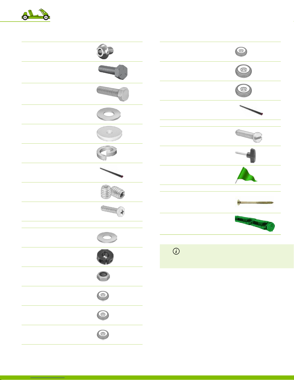
Overview of the required hardware
№ DESCRIPTION REFERENCE
Overview of the required hardware
№ DESCRIPTION REFERENCE
5 Button Socket Head Cap Screw
Zinc Plated, Steel, M8, 12mm L
TOTAL OF 5 PROVID ED P N 12515
1 Hex head cap screw
5/16”‑18, 1.25 L
4.0 HP MODEL PN 12 5 43
1 Hex Cap Screw
1/4”‑20, 1” L
2.5 HP MODEL PN 12554
1 Flat Washer
5/16” ID, 7/8” OD
PN 12 516
1 Fender washer
5/16” ID, 1‑1/8” OD
PN 12555
1 Lock washer
5/16” ID
1 Clutch Key
3/16”, 1/2” L
PN 12 55 7
2 Set Screw
Clutch
PN 12 56 3
1 Pan head
M6, 12 mm L
4.0 HP MODEL P N 125 64
PART 8
Flat Washer
5/16” ID, 7/8” OD
3 SINGLE WHEEL KIT PN 12 516
2 LIVE A XLE KIT P N 12516
2 Shaf t Collar
5/8” ID
PN 12540
2 Undriven wheel
10” D
LIVE A XLE KIT PN 125 91
1 Rear driven wheel
12” D
SINGLE WHEEL KIT PN 12 59 2
3 Undriven wheel
12” D
SINGLE WHEEL KIT PN 1259 3
1 Key
3/16” square, 1”L
PN 12 53 9
PART 9
2 Fillister Head Screw
5/16”‑18, 3/4” L
PN 125 5 3
1 T‑Handle
Quick Release Pin
PN 125 4 2
1 Flag
Plyy ag
PN 125 3 5
PART 10
20 Spax Screw
1 #8, 1‑1/2” L
PN 12519
1 Green Elastic Cord
3/16” OD, 18” L
PN 12 517
Note There are 2 types of button socket head cap screws
provided in every kit. They appear to be similar in
size but are not. The easiest way to dierentiate the
2 sizes, is by the number of screws provided.
2 Lock Nut
5/8"‑11
PN 12 50 6
1 Rear driven wheel
10”D
SINGLE WHEEL KIT PN 12 59 0
3 Undriven wheel
10” D
SINGLE WHEEL KIT PN 12 59 1
2 Rear driven wheel
10”D
LIVE A XLE KIT PN 125 9 0
10 Putting the go‑kart together
40
150718 PLYFL Y rev A_GoKart | A ug u st 7, 20 1 5 5:0 8 PM
Page 45
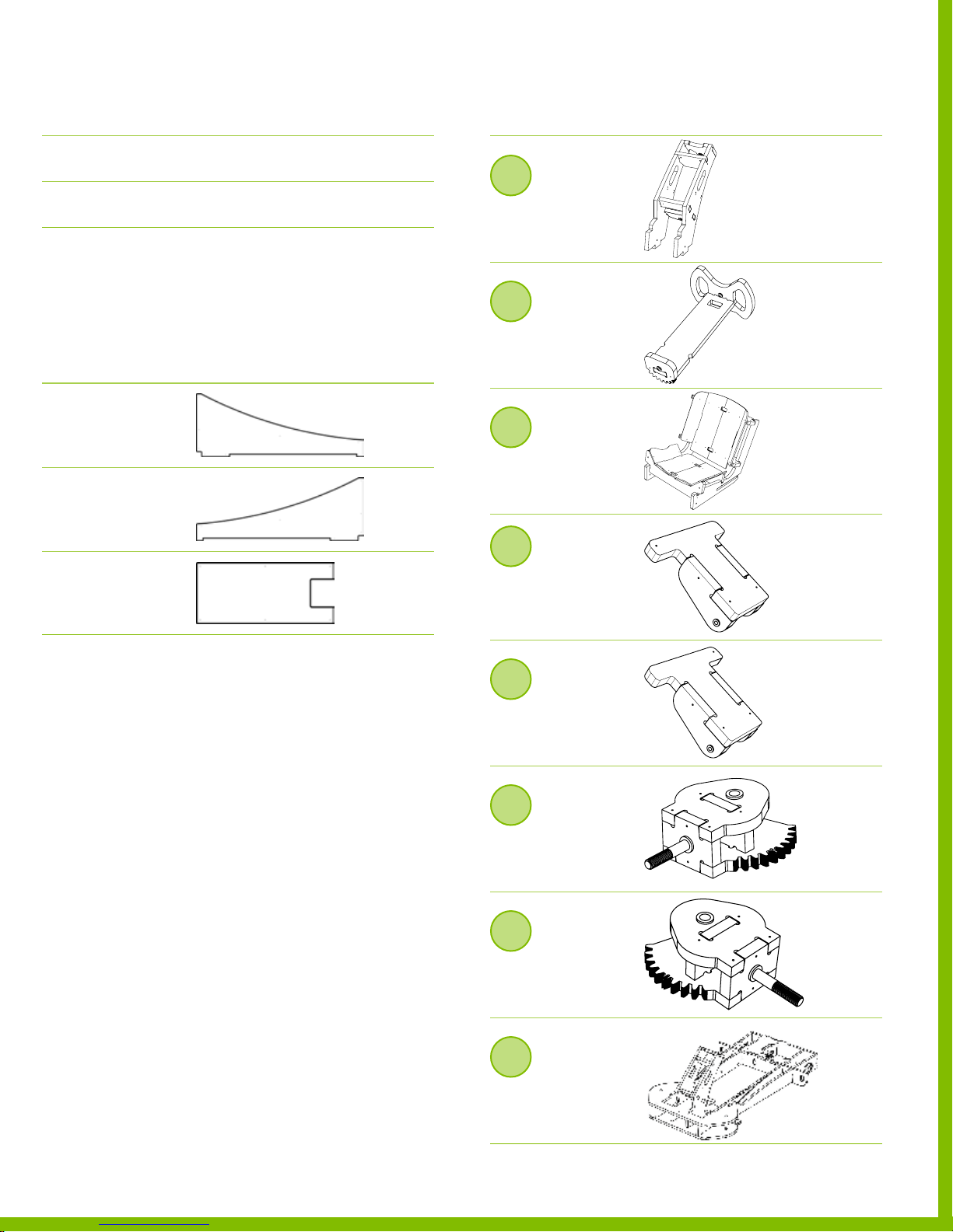
Overview of the required but not provided
DESCRIPTION REFERENCE
Overview of the required assemblies
DESCRIPTION REFERENCE
Motor Oil
Gas
Approximately 1 quart of 10W30 Motor Oil
Regular unleaded gas.
Overview of the required wooden parts
DESCRIPTION REFERENCE
Part 53
Fairing Left
PLYWOOD SHEET 4
Part 54
Fairing Right
PLYWOOD SHEET 4
Part 55
Fairing Front
PLYWOOD SHEET 4
2
Fixed steering column
Assembly
PAR TS 13 ‑18
3
Steering column
Assembly
PARTS 19 ‑21
4
Seat
Assembly
PARTS 22‑33
5
Gas Pedal
Assembly
PARTS 34, 3 6‑37
6
Brake Pedal
Assembly
PARTS 35, 3 8‑3 9
7
Left Spindle
Assembly
PARTS 1, 3, 5, 7
8
Right Spindle
Assembly
PARTS 2, 4, 6, 8
9
Frame
Assembly
150718 PLYFL Y rev A_GoKart | A ug u st 7, 20 1 5 5:0 8 PM
PARTS 21‑28
PlyFly Go‑Kart Instruction Guide • 2015 Release
41
Page 46
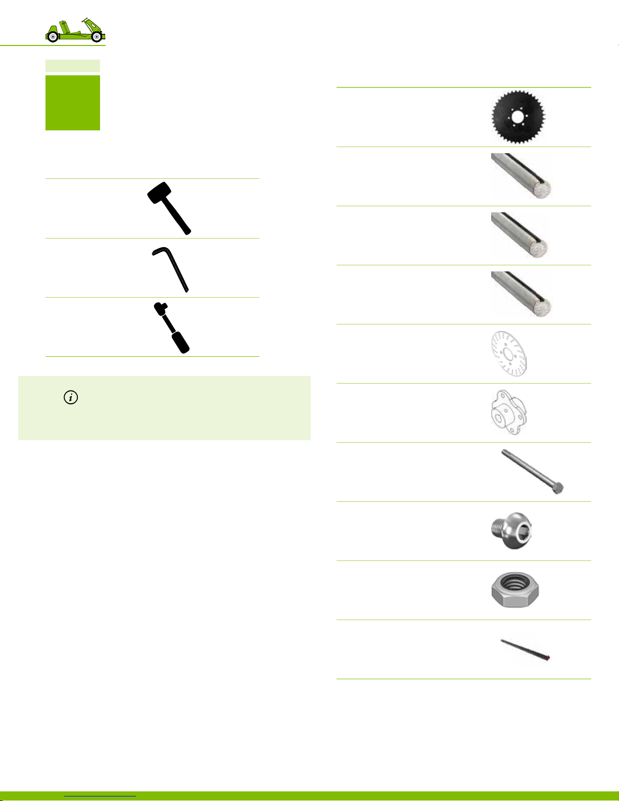
Chapter 10
1
PAR T
Required hardware
№ DESCRIPTION REFERENCE
1 Sprocket
5/8” bore diameter
60 Tooth, #35 Chain
PN 12 52 2
Recommended tools
DESCRIPTION REFERENCE
Dead blow Hammer
or mallet
Allen Wrench
Socket Wrench
Note There are 2 types of button socket head cap screws
provided in every kit. They appear to be similar in
size but are not. The easiest way to dierentiate the
2 sizes, is by the number of screws provided.
1 Drive Shaft
Steel, Keyed, 5/8” D, 18” L
SINGLE WHEEL KIT PN 125 8 0
1 Drive Shaft
Steel, Keyed, 5/8” D, 33” L
LIVE A XLE KIT – 10” WHEELS PN 125 81
1 Drive Shaft
Steel, Keyed, 5/8” D, 36” L
LIVE A XLE KIT – 12” WHEELS PN 12 5 82
1 Brake Disc
PN 12 53 2
1 Brake Disc Hub
PN 12 53 3
1 Long Hex Bolt
Axle Grade 5, 5/8”‑11, 11” L
SINGLE WHEEL KIT PN 12 5 02
4 Button Socket Head Cap Screw
Zinc Plated, Steel, 5/16”‑24, 1/2” L
TOTAL OF 4 PROVID ED P N 125 59
4 Thin Nut
Grade 5, 5/16”‑24
PN 12 52 0
1 Key
3/16” square, 1”L
PN 12 53 9
150718 PLYFL Y rev A_GoKart | A ug u st 7, 20 1 5 5:0 8 PM
10 Putting the go‑kart together
42
Page 47
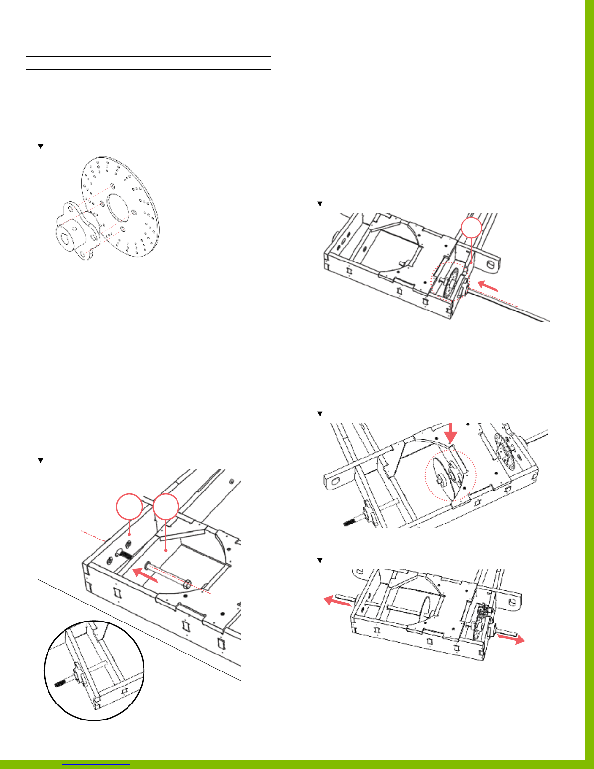
Part 1 Install the rear axle
INSTRUCTIONS
1. Assemble the hub and brake disc using the
button head screws and locknuts.
‒ Use 4 button head screws and 4 locknuts
‒ Total of 4 locations.
Note orientation of the par ts.
2. Loosen set screws on all 3 of the mounted bearings
‒ Be sure no screw extends into the interior
of the bearings; as this will prevent
the drive shaft insertion.
3. Insert the drive shaft and bolts
‒
SINGLE WHEEL KIT; continue to step 4.
LIVE A XLE KIT; continue to step 5.
‒
4. Insert the long hex bolt from the interior of the frame
through the bushing located on part 40 and the
mounted bearing located on part 42.
‒ If there is too much resistance to insert the
long hex bolt, temporarily loosen the mounting screws
so the mounted bearing is loose; or remove the
mounted bearing, slide the long hex bolt through and
then re‑mount the mounted bearing.
Note location of the long hex bolt.
5. Insert the drive shaft by sliding it through
the outer mounted bearing located on part 43 only.
‒ If there is too much resistance to insert the
drive shaft, temporarily loosen the mounting screws
so the mounted bearing is loose; or remove the
mounted bearing, slide the drive shaft and then
re‑mount the mounted bearing.
‒ Rotate the bearing in its seat so that it is parallel to the
center frame rails.
6. Once the drive shaft is through the outer
mounted bearing, insert the brake disc on the end.
‒ Use the key to lock the brake disc to the drive shaft.
Note the orientation of the disc brake.
43
7. Continue to slide the drive shaft through the assembly,
through the center mounted bearing, and then insert the
sprocket on then end.
‒ Use the key to lock the brake disc to the drive shaft.
‒
SINGLE WHEEL KIT is complete.
LIVE A XLE KIT continue to step 8.
‒
Note location and orientation of the bushing
4042
150718 PLYFL Y rev A_GoKart | A ug u st 7, 20 1 5 5:0 8 PM
8. Continue to insert the drive shaft through the assembly
and through the nal mounted bearing located on part 42.
Note the drive shaf t extends equal distances on both sides of the assembly.
9. Ensure all the hardware on mounted bearings are fully
tightened
.
PlyFly Go‑Kart Instruction Guide • 2015 Release
43
Page 48
Chapter 10
2
PAR T
Recommended tools
DESCRIPTION REFERENCE
Dead blow Hammer
or mallet
Allen Wrench
Socket Wrench
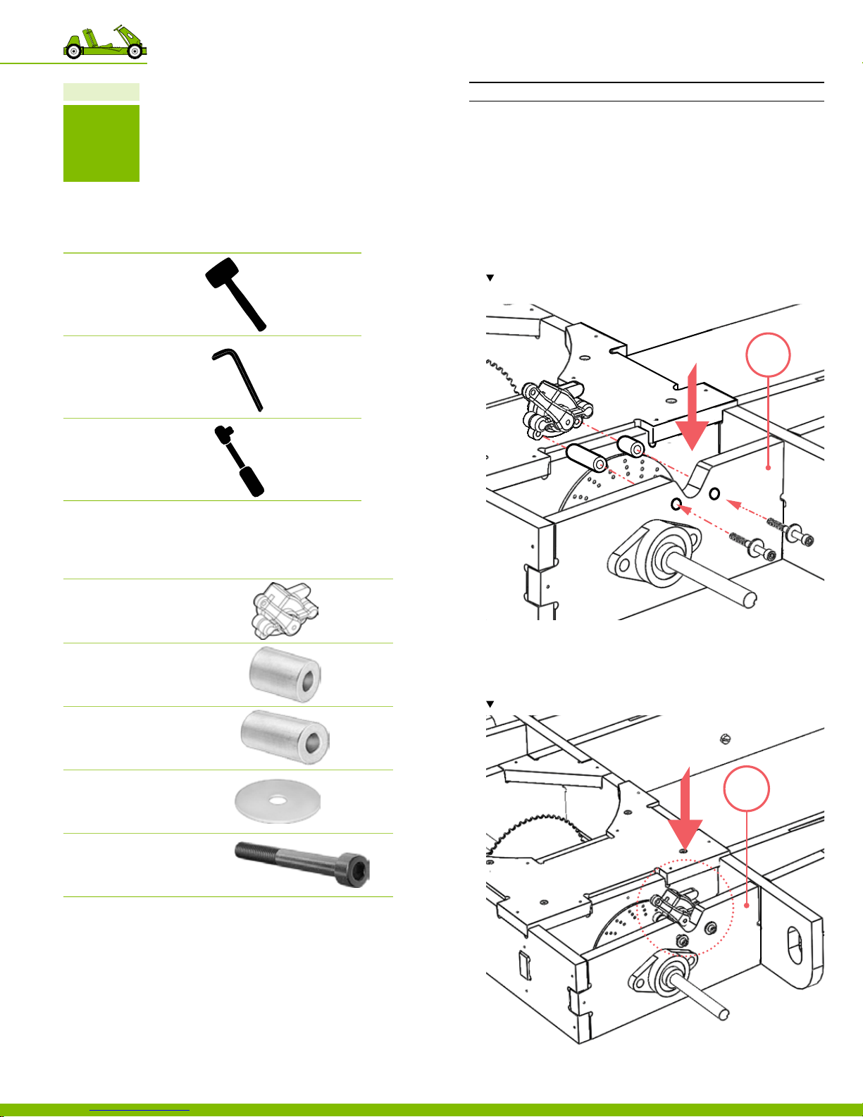
Part 2 Install the brake caliper
The brakes will initially be installed and then adjusted.
INSTRUCTIONS
1. Insert the socket head cap screws with an oversized at
washer through the holes located on part 43,
‒ Use 1 socket head cap screw with
1 oversized at washers per location.
‒ Total 2 locations
2. Insert into the aluminum spacers on the opposite side of
part 43.
Note the location and orientation of the brake caliper. As well as the locations of
the shor t spacer and the long spacer.
43
Required hardware
№ DESCRIPTION REFERENCE
1 Brake Caliper
PN 12 53 1
1 Shor t Aluminum Spacer
1/2” OD, 1/4” ID, 7/8” L
PN 12 547
1 Long Aluminum Spacer
1/2” OD, 1/4” ID, 1‑1/16” L
PN 12 54 8
2 Oversized Flat Washer
Zinc, M6
PN 12 54 9
2 Socket Head Cap Screw
Black oxide, M6, 55mm L
PN 12 55 0
3. Place brake caliper into the cutout located at the rear of
part 43 and insert the hardware.
4. Secure the brake caliper in place, using
the metric Allen wrench provided.
Note the location and orientation of the brake caliper.
43
150718 PLYFL Y rev A_GoKart | A ug u st 7, 20 1 5 5:0 8 PM
10 Putting the go‑kart together
44
Page 49
Chapter 10
3
PAR T
Part 3 Install the steering column assembly
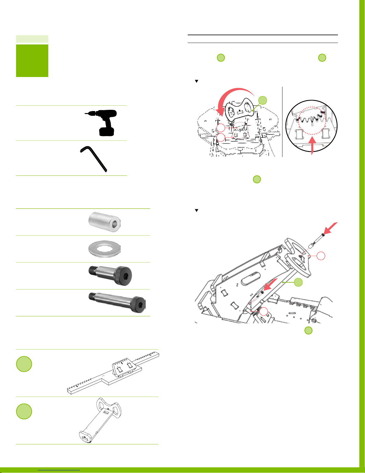
INSTRUCTIONS
1. Position 3, so that the gear aligns with those on 1.
‒ Be sure the gear alignment marks located on
parts 20 & 12 line up.
Note-the orientation and alignment of the gear teeth
Recommended tools
DESCRIPTION REFERENCE
Electric Driver
Allen Wrench
or ratcheting Allen wrench
Required hardware
№ DESCRIPTION REFERENCE
1 Nylon Spacer
3/4” OD, 3/8” ID, 1‑1/4” L
PN 12 54 6
4 Flat Washer
5/16” ID, 7/8” OD
PN 12 516
3
20
12
2. Insert the shoulder screws.
‒ Insert the short shoulder screw through the bushing
located on part 20 of
.
3
‒ Insert the long shoulder screw with the nylon spacer
through the tee nut located on part 21.
‒ Total 2 locations, 2 shoulder screws.
Note-the orientation of the bolt; be sure the head faces down
(toward the g round).
21
Shor t Shoulder Screw
1
3/8” D, 1” L, 5/16”‑18
PN 12 513
Long Shoulder Screw
1
3/8” D, 2‑1/4” L, 5/16”‑18
PN 12514
Required assemblies
DESCRIPTION REFERENCE
1
Steering rack
Assembly
Pa r t s 9 ‑12
3
Steering Column
Assembly
150718 PLYFL Y rev A_GoKart | A ug u st 7, 20 1 5 5:0 8 PM
PARTS 19 ‑21
3
21
3. To secure, tighten both the shoulder screws 3.
‒ Total 2 locations.
PlyFly Go‑Kart Instruction Guide • 2015 Release
45
Page 50
Chapter 10
8
4
PAR T
Recommended tools
DESCRIPTION REFERENCE
Hammer
Required hardware
№ DESCRIPTION REFERENCE
2 Shor t Hex Bolt
Grade 5, 5/8”‑11, 6.5” L
PN 12503
2 Lock Nut
5/8” ID
PN 12 50 6
Part 4 Install the steering spindles
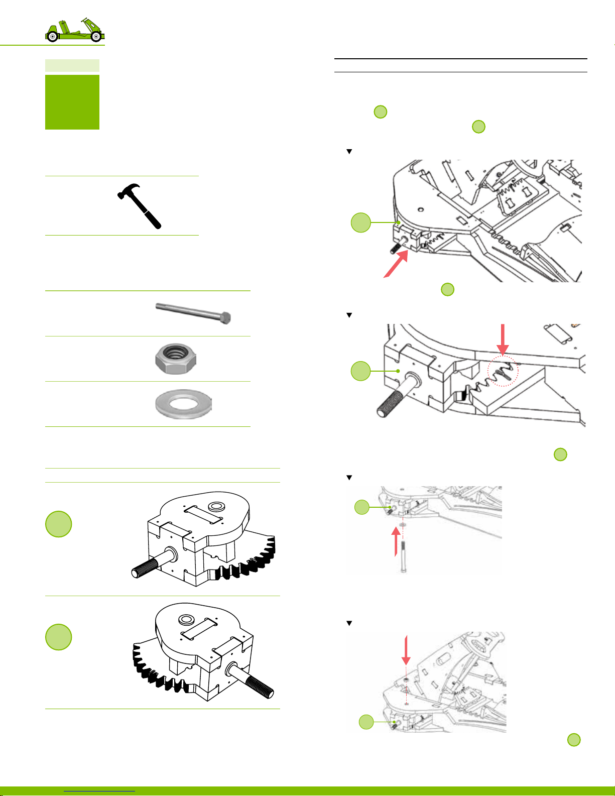
INSTRUCTIONS
1. Slide the steering rack all the way to the right.
7
2. Insert
‒ Check that the bushings on
before installing.
Note the location and orientation of the assemblies.
3. Align the gear teeth of 7 with the gear alignment mark
located on the steering rack assembly gear.
Note the location and orientation of the alignment mar ks.
with the bolt facing out.
7
7
7
are completely seated
4 Fender Washer
3/4” OD, 5/8” ID
PN 12 50 5
Required assemblies
DESCRIPTION REFERENCE
7
Left Spindle
Assembly
PARTS 1, 3, 5, 7
8
Right Spindle
Assembly
PARTS 2, 4, 6, 8
4. Insert the short hex bolt with a washer, starting from the
bottom and insert through the bushings found on
7
and
then through the top of the frame.
Note the order of the hardware insertion.
7
5. Using a hammer, tap into place.
6. Insert a washer over the short hex bolt and secure it with
a locknut.
Note the order of the hardware insertion.
150718 PLYFL Y rev A_GoKart | A ug u st 7, 20 1 5 5:0 8 PM
10 Putting the go‑kart together
46
7
7. Repeat steps 1 through 6 on the opposite side using
8
.
Page 51
Chapter 10
5
PAR T
Part 5 Install the gas & brake pedals
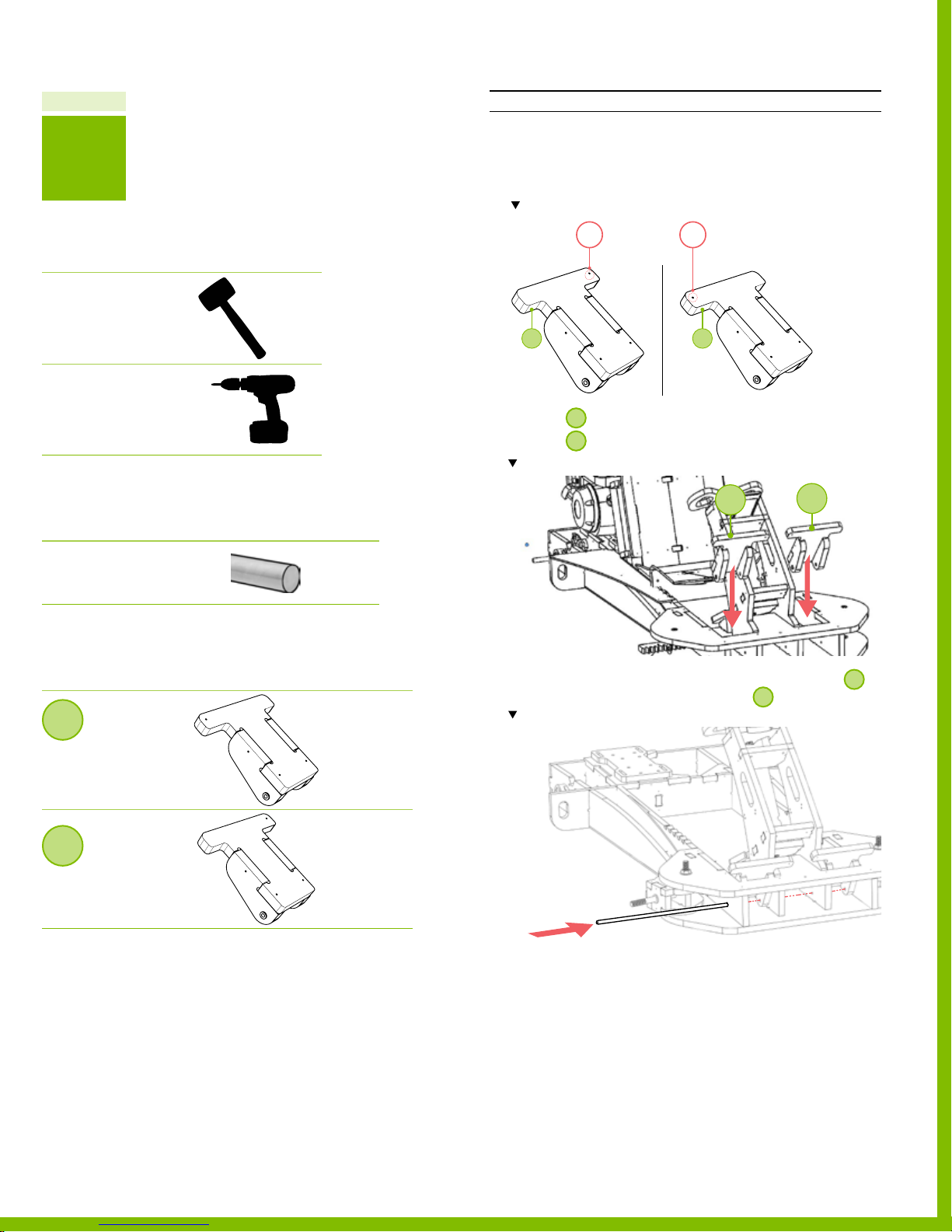
INSTRUCTIONS
1. Each assembly has a long tab with a hole. The position of
the pedal is dictated by these holes. The holes should be
pointing towards the middle of the xed steering column.
Note the right and left pedals tabs, holes, and their position in the Assembly.
Recommended tools
DESCRIPTION REFERENCE
Dead blow Hammer
or mallet
Electric Driver
Required hardware
№ DESCRIPTION REFERENCE
1 Precision Rod
1/4” D, 18” L
PN 12 50 7
Required Assemblies
DESCRIPTION REFERENCE
5
1
6 5
2
2. Position 5 on the right of the xed steering column.
6
3. Position
Note location and or ientation of the assembly 5 & 6.
on the left of the xed steering column.
5
6
4. Insert the precision rod through the holes located in
and then through the holes located in
Note location of the precision rod.
.
6
5
Gas Pedal
Assembly
Parts 34, 36‑37
6
Brake Pedal
Assembly
Parts 35, 38‑39
150718 PLYFL Y rev A_GoKart | A ug u st 7, 20 1 5 5:0 8 PM
5. Using a hammer, tap into place.
6. Test the alignment of each pedal assembly.
‒ Each pedal should be able to move freely and
independently (some drag is expected).
PlyFly Go‑Kart Instruction Guide • 2015 Release
47
Page 52
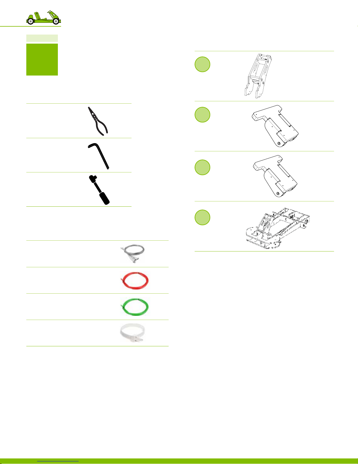
Chapter 10
Reference Assemblies
DESCRIPTION REFERENCE
6
PAR T
Recommended tools
DESCRIPTION REFERENCE
Needle Nose Pliers
Allen Wrench
Socket Wrench
Required Assemblies
№ DESCRIPTION REFERENCE
1 Control Cable
1/16” D, throttle & brake control cable
PN 12525
2
Fixed steering
column
Assembly
PAR TS 13 ‑18
5
Gas Pedal
Assembly
Parts 34, 36‑37
6
Brake Pedal
Assembly
Parts 35, 38‑39
9
Frame
Assembly
PARTS 21‑28
1 Red Throttle Cable
Brake conduit, 5’ L
PN 12 527
1 Green Throttle Cable
Gas conduit, 6’ L
PN 12 52 8
6 Zip Tie
10lb Nylon, White, 7/8” D, 4” L
PN 12 55 8
10 Putting the go‑kart together
48
150718 PLYFL Y rev A_GoKart | A ug u st 7, 20 1 5 5:0 8 PM
Page 53
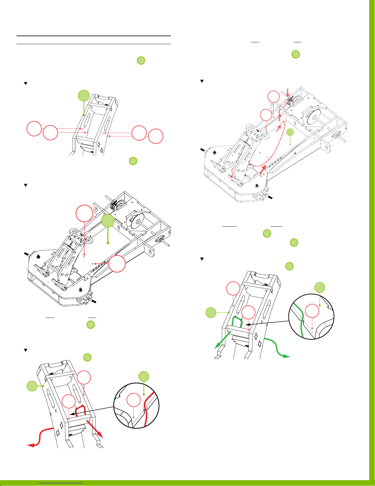
Part 6 Install the gas & brake cables
INSTRUCTIONS
1. Loop 4 zip ties through the holes located on 2.
‒ Loosely tighten the zip ties, leaving a large loop so later,
the cables can slide through easily.
Note the locations of the zip ties.
4. Continue to run the red cable on the left side of
the go‑kart
‒ Through the cable ties located on
9
,
‒ through the slots located on part 40 & 43,
‒ and into the brake caliper assembly.
Note path of the red cable.
2
1
2
3
2. Loop 2 zip ties through the holes located 9.
‒ Loosely tighten the nylon cable ties, leaving a large loop
so later, the cables can slide through easily.
Note the locations of the zip ties.
1
9
2
43
41
9
4
5. Run the green cable on the right side of the go‑kart
‒ Through the interior of
‒ through the cable ties located on
‒ through the hole located on the right side of part 17.
Note the location and direction of the green cable. Be sure to seat the
green cable in the notches located on part 17 of 3.
and then
2
and then
2
3. Run the red cable on the left side of the go‑kart
‒ Through the interior of
2
‒ through zip ties located on part 13 and then
‒ through the hole located on the left side of part 17.
Note the location and direction of the red cable. Be sure to seat the red cable in
the notches located on part 19 of
.
3
13
2
17
150718 PLYFL Y rev A_GoKart | A ug u st 7, 20 1 5 5:0 8 PM
19
14
2
3
17
PlyFly Go‑Kart Instruction Guide • 2015 Release
3
19
49
Page 54
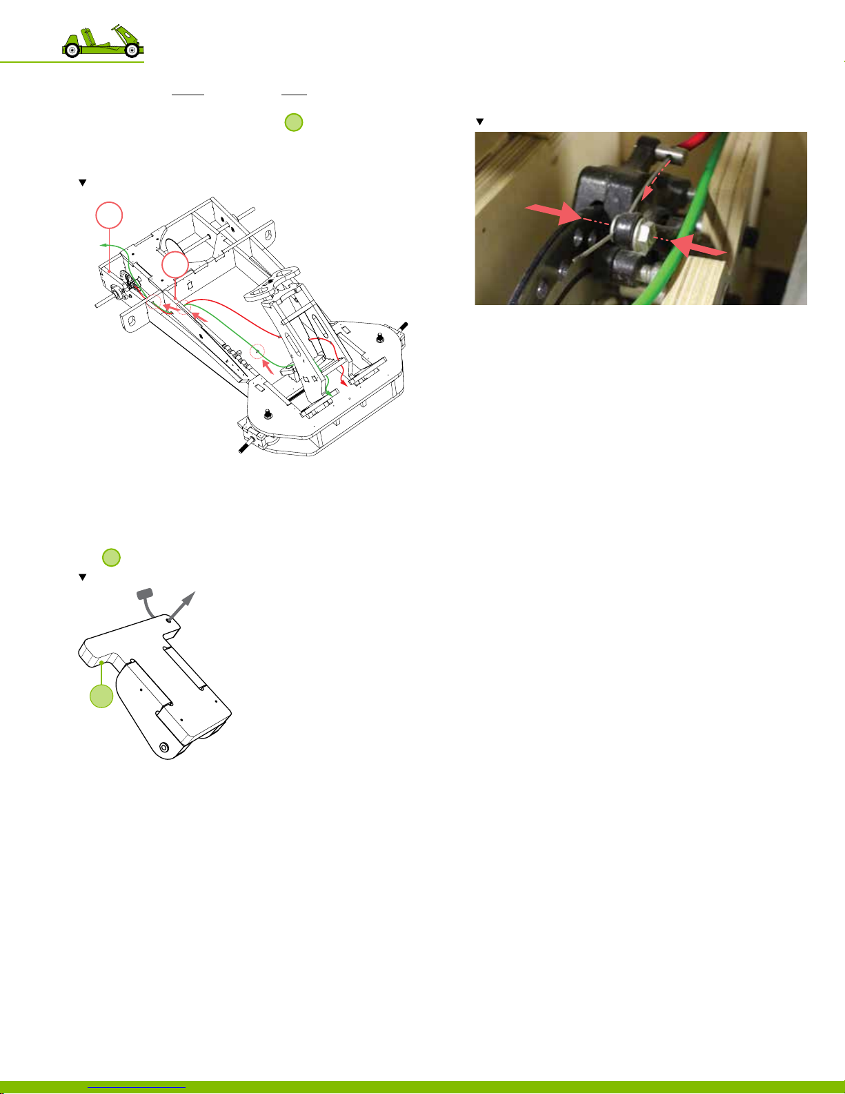
6. Continue to run green cable on the right side of
the go‑kart
‒ Through the cable ties located on
9
,
‒ through the slots located on part 40 & 43,
‒ and leave slack to secure to the engine later.
Note path of the red cable.
43
41
11. Feed the brake control cable through a washer into the
tting located on the brake.
Note path of the brake control cable throug h the brake caliper.
12. Secure the control cable in place using a small wrench or
pliers.
13. Test brake pedal to ensure proper movement of brake.
7. Secure the nylon cable ties by tightening them.
8. Use the needle nose pliers to clip any excess
cable tie material.
9. Feed the brake control cable through the hole located in
6
the
and into the red cable.
Note path of the brake control cable throug h the brake pedal.
6
10. Fish the brake control cable through the red cable all the
way to the end.
150718 PLYFL Y rev A_GoKart | A ug u st 7, 20 1 5 5:0 8 PM
10 Putting the go‑kart together
50
Page 55
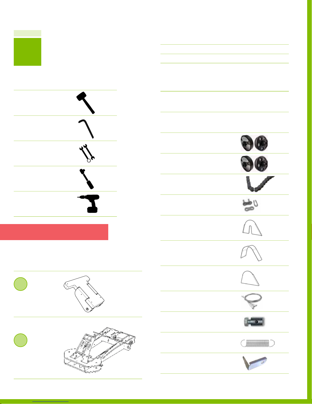
Chapter 10
Required but not provided
№ DESCRIPTION REFERENCE
7
PAR T
Recommended tools
DESCRIPTION IMAGE REFERENCE
Dead blow Hammer
or mallet
Metric Allen Wrench
included with mounted bearing
Wrench
Socket Wrench
Oil Type & Amount
Ga s Type
TYPE & AMOUNT
TYPE
Required hardware
№ DESCRIPTION REFERENCE
Gas Powered Engine
1
2.5 HP MODEL
Gas Powered Engine
1
4.0 HP MODEL
1 Clutch
#35 Chain, 11 Tooth Pulley for 5/8” D
2.5 HP MODEL PN 125 76
1 Clutch
#35 Chain, 12 Tooth Pulley for 3/4” D
4.0 HP MODEL PN 12 57 7
1 Roller Chain
#35 Chain, 29‑5/8” L
PN 12 524
Box 2
Box 2
Electric Driver
Note Be sure not to lose attached key,
set screws and bolt to hold clutch in place.
Required assemblies
DESCRIPTION REFERENCE
5
Gas Pedal
Assembly
Parts 34, 36‑37
9
Frame
Assembly
PARTS 21‑28
150718 PLYFL Y rev A_GoKart | A ug u st 7, 20 1 5 5:0 8 PM
1 Master Chain Link
#35 Roller Chain connector
PN 12 53 4
1 Part 56
Clutch Guard Side
Engine Mounting Plate
PN 12 0 0 5
1 Part 57
Clutch Guard Top
Top C o ver
PN 12 0 0 6
1 Part 58
Clutch Guard Cover
Outside Cover
PN 12 0 07
1 Control Cable
1/16” D, throttle & brake control cable
PN 12525
1 Throttle cable clamp
PN 12 53 7
1 Extension Spring
Black‑Oxide, Precision
PN 12 56 0
1 Throt tle Return Clip
4.0 HP MODEL
PN 12 56 1
PlyFly Go‑Kart Instruction Guide • 2015 Release
51
Page 56
Required hardware
№ DESCRIPTION REFERENCE
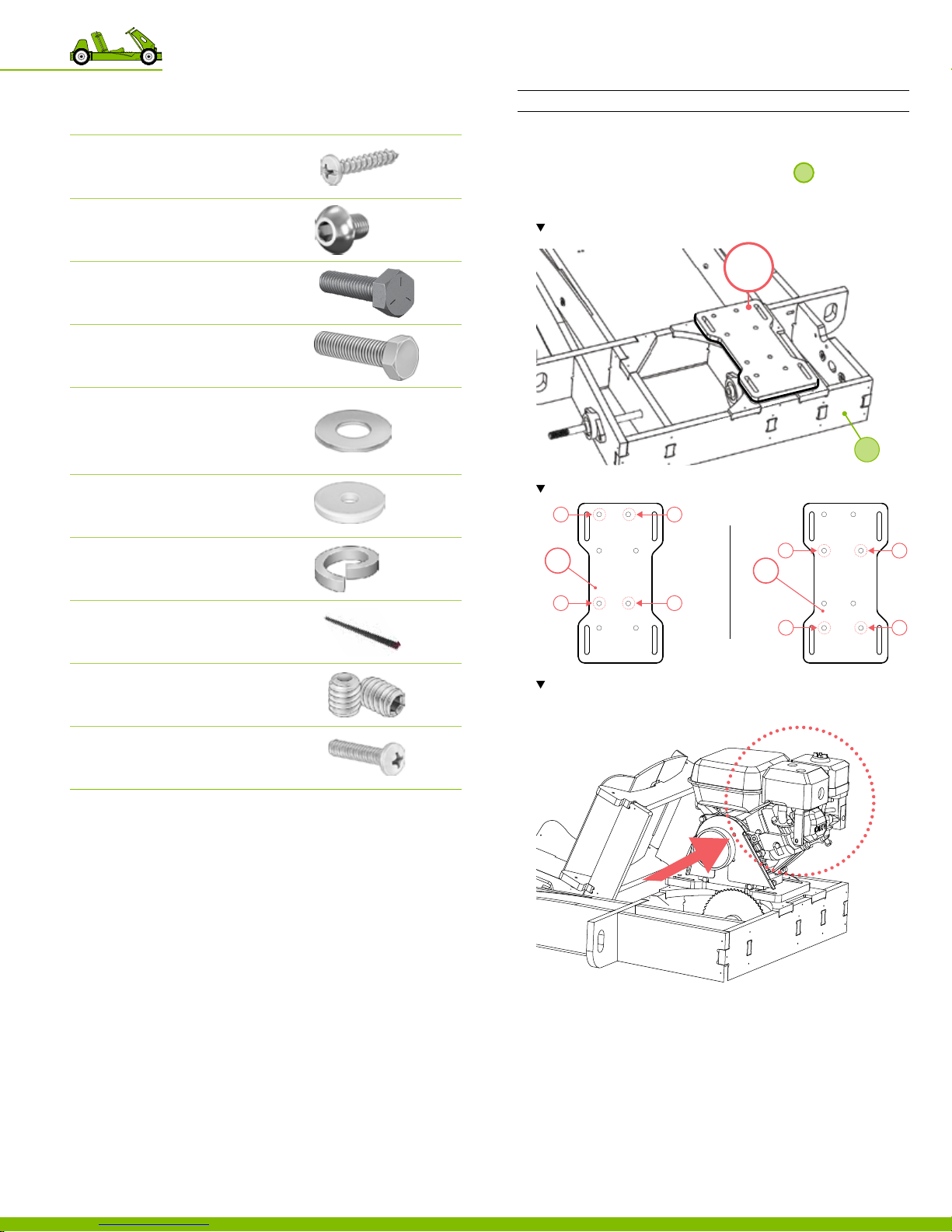
Part 7 Install the engine and drive train
The engine arrives with no oil, no conguration is required.
8 Sheetmetal Screw
Galvanized, #6
PN 12 551
5 Button Socket Head Cap Screw
Zinc Plated, Steel, M8, 12mm L
TOTAL OF 5 PROVID ED P N 12515
1 Hex head cap screw
5/16”‑18, 1.25 L
4.0 HP MODEL PN 12 5 43
1 Hex Cap Screw
1/4”‑20, 1” L
2.5 HP MODEL PN 12554
1 Flat Washer
5/16” ID, 7/8” OD
PN 12 516
1 Fender washer
5/16” ID, 1‑1/8” OD
PN 12555
1 Lock washer
5/16” ID
1 Clutch Key
3/16”, 1/2” L
PN 12 55 7
INSTRUCTION
1. Stand the engine on part 50 located on
9
,
aligning the engine mounting holes to the tee nut pattern
(installed previously) appropriate for the engine model.
Note the location of the engine mount.
50
Note the location of the tee nut bolting pattern on part 50.
1
50
2.5 HP
2
3
1
50
4
4.0 HP
2
9
3
4
2 Set Screw
Clutch
PN 12 56 3
1 Pan head
M6, 12 mm L
4.0 HP MODEL P N 125 64
Note the direction and orientation of the engine within the go-kart.
2. For next installation step:
2.5 HP MODEL continue to step 3.
‒
4.0 HP MODEL continue to step 4.
‒
150718 PLYFL Y rev A_GoKart | A ug u st 7, 20 1 5 5:0 8 PM
10 Putting the go‑kart together
52
Page 57
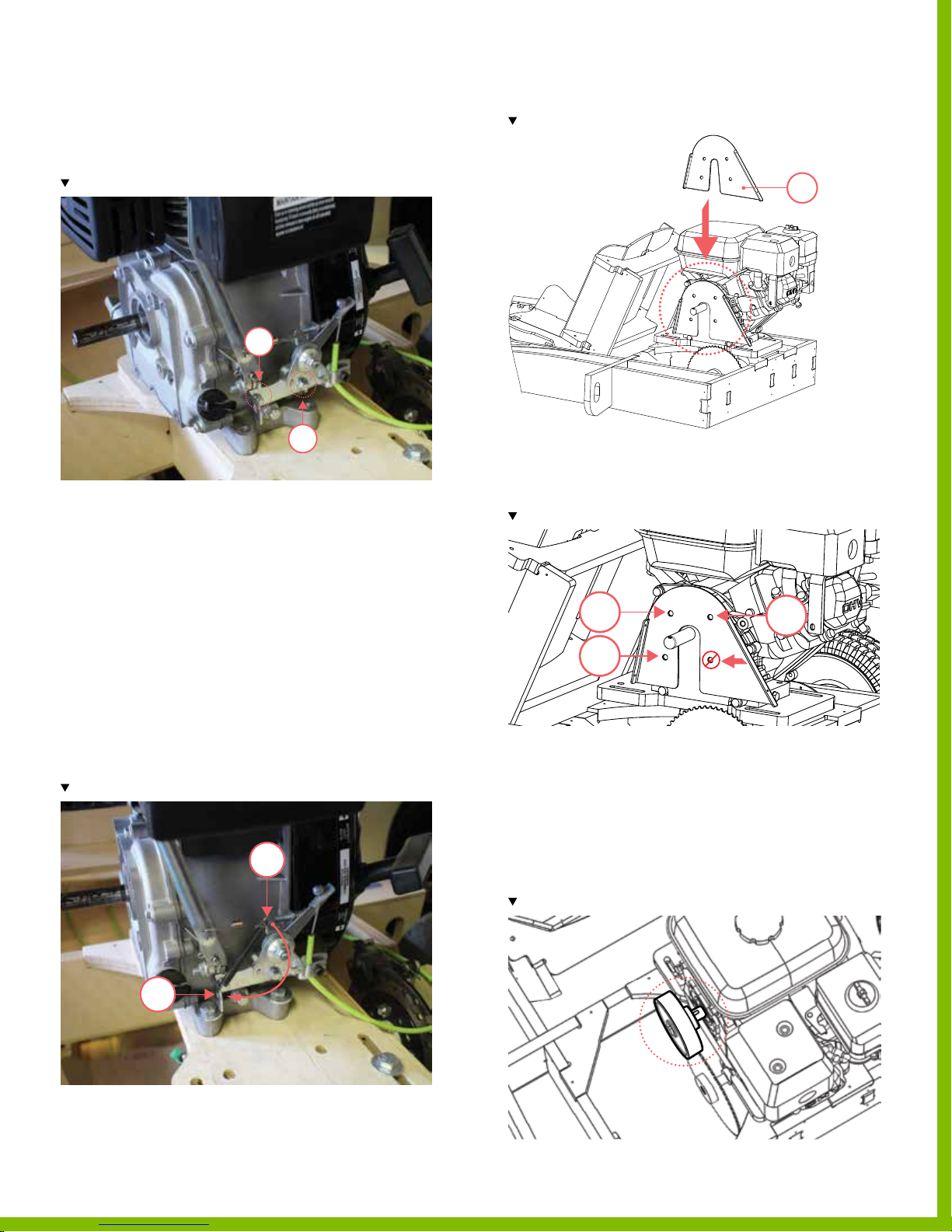
3. Remove the 2 bolts holding the throttle linkage; to be able
to secure the engine to part 50.
‒ Remove 2 bolts.
‒ Total of 2 locations.
Note the location of the 2 throttle linkage bol ts.
1
8. Slide part 56 into the space located on the engine side.
Note the location of slot.
5656
2
4. Using a socket wrench secure the engine bolts to part 50.
‒ Use 4 bolts.
‒ Total of 4 locations.
5. For next installation step:
2.5 HP MODEL continue to step 6.
‒
4.0 HP MODEL continue to step 8.
‒
6. Secure the throttle linkage back into place using the bolts.
‒ Use 2 bolts.
‒ Total of 2 locations.
7. Install the extension spring, by hooking one end
through the hole located on the throttle linkage. Then
using pliers, stretch the extension spring and hook it
through the second hole on the opposite side of the
throttle linkage.
Note the location of the extension spring.
1
9. Secure part 56, using M8 screws.
‒ Use 3 screws.
‒ Total of 3 locations.
Note the locations of the 3 screws.
1
3
2
10. Slide the clutch over the engine crank shaft.
‒ Be sure the set screws on the clutch are backed‑out
enough to be able to slide the clutch over
the crankshaft.
‒ Be sure the small sprocket is facing toward the engine
and the set screws are facing away from the engine.
‒ Be sure to align the keyway on the clutch with the
keyway on the drive shaft.
Note the orientation of clutch; the small sprocket should face the engine.
2
!
150718 PLYFL Y rev A_GoKart | A ug u st 7, 20 1 5 5:0 8 PM
PlyFly Go‑Kart Instruction Guide • 2015 Release
53
Page 58
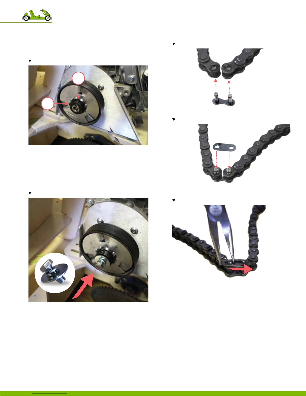
11. Insert 1/2” clutch key through the center of the clutch.
12. Using an Allen wrench tighten the set screws.
‒ 2 set screws.
‒ Total of 2 screws.
Note the locations of the 3 set screws.
2
1
13. Using a wrench, tighten the hex head cap screw
assembled with a lock washer and a fender washer to
secure the clutch.
‒ Tighten hex head cap screw until the lock washer is
compressed.
‒ If necessary, pull the starter cord to prevent the
crankshaft from rotating while tightening.
Note the order of the assembled hardware.
15. Connect the chain by sliding the posts of the master link
into the holes located at the ends of the chain.
Note the order of the assembled hardware.
16. Add the master link plate.
Note the order of the assembled hardware.
17. Secure the master link, using the retaining clip; snapping
it into place.
Note the order of the assembled hardware.
14. Slide the chain, over both sprockets.
‒ Be sure to align the clutch sprocket with the
drive shaft sprocket vertically.
10 Putting the go‑kart together
54
18. Tension the chain.
‒ Slide the engine forward until chain is taut.
19. Secure the engine in place using the bolts located on
part 50.
20. Test the rear wheel drive by spinning the drive shaft.
‒ Be sure the shaft can spin freely with the chain.
21. For instructions on how to install the throttle control cable
2.5 HP MODEL continue to step 22.
‒
4.0 HP MODEL continue to step 26.
‒
150718 PLYFL Y rev A_GoKart | A ug u st 7, 20 1 5 5:0 8 PM
Page 59
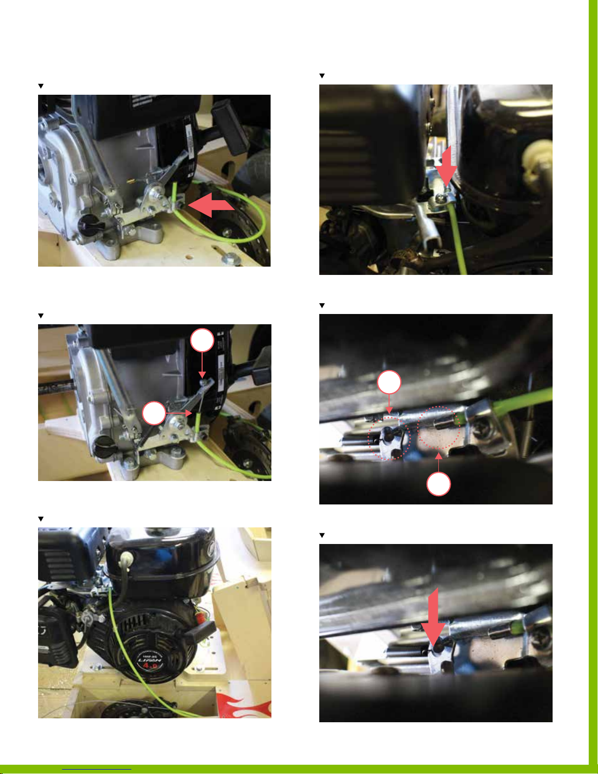
22. Secure the green cable loosely in the
throttle control linkage.
Note the location of the green cable.
26. Secure the green cable loosely in the clamp.
Note the location of the green cable.
23. Feed the throttle control cable through the hole
located on the throttle control linkage and then into the
green cable.
Note the location of the green cable.
1
2
24. For the next installation instruction, continue to step 32.
25. Thread the green cable into the right side of the engine.
Note the location of the green cable.
27. Feed the throttle control cable through the hole located
on the throttle linkage.
Note the locations of the throttle control cable.
1
2
28. Install the extension spring, by hooking one end to the
hole located on the throttle linkage.
Note the location of the extension spring.
150718 PLYFL Y rev A_GoKart | A ug u st 7, 20 1 5 5:0 8 PM
PlyFly Go‑Kart Instruction Guide • 2015 Release
55
Page 60
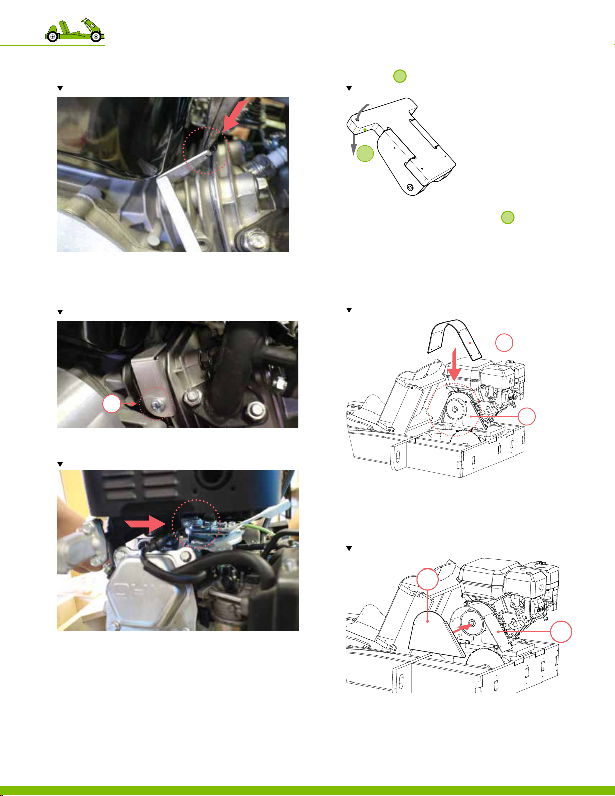
29. Using pliers, hook the other end of the extension spring to
the throttle return clip.
Note the location of the extension spring.
30. Secure the throttle return clip to the engine using a screw.
‒ Use 1 M6 screw.
‒ Total 1 location
Note the location of the throttle return clip.
32. Continue to feed the throttle control cable all the way
through to
Note the location of the throttle control cable.
5
.
5
33. Secure the throttle control cable using the
throttle cable clamp at the bottom of
.
5
‒ Be sure the control cable is taut, before tightening the
throttle clamp.
34. Secure the green cable fully at the start location of the
throttle linkage.
35. Test the gas pedal to ensure proper movement of throttle.
36. Place part 57 over part 56.
Note the location part 57.
57
!
1
31. Slightly loosen this nut so that the throttle can move freely
when the gas pedal is pressed.
Note the location of the nut.
!
56
37. Secure part 57 to part 56, using sheet metal screws.
‒ Use 4 sheet metal screws.
‒ Total of 4 locations.
38. Place part 58.
Note the location part 58.
58
150718 PLYFL Y rev A_GoKart | A ug u st 7, 20 1 5 5:0 8 PM
57
10 Putting the go‑kart together
56
39. Secure part 58 to part 57, using sheet metal screws.
‒ Use 4 sheet metal screws.
‒ Total of 4 locations.
Page 61
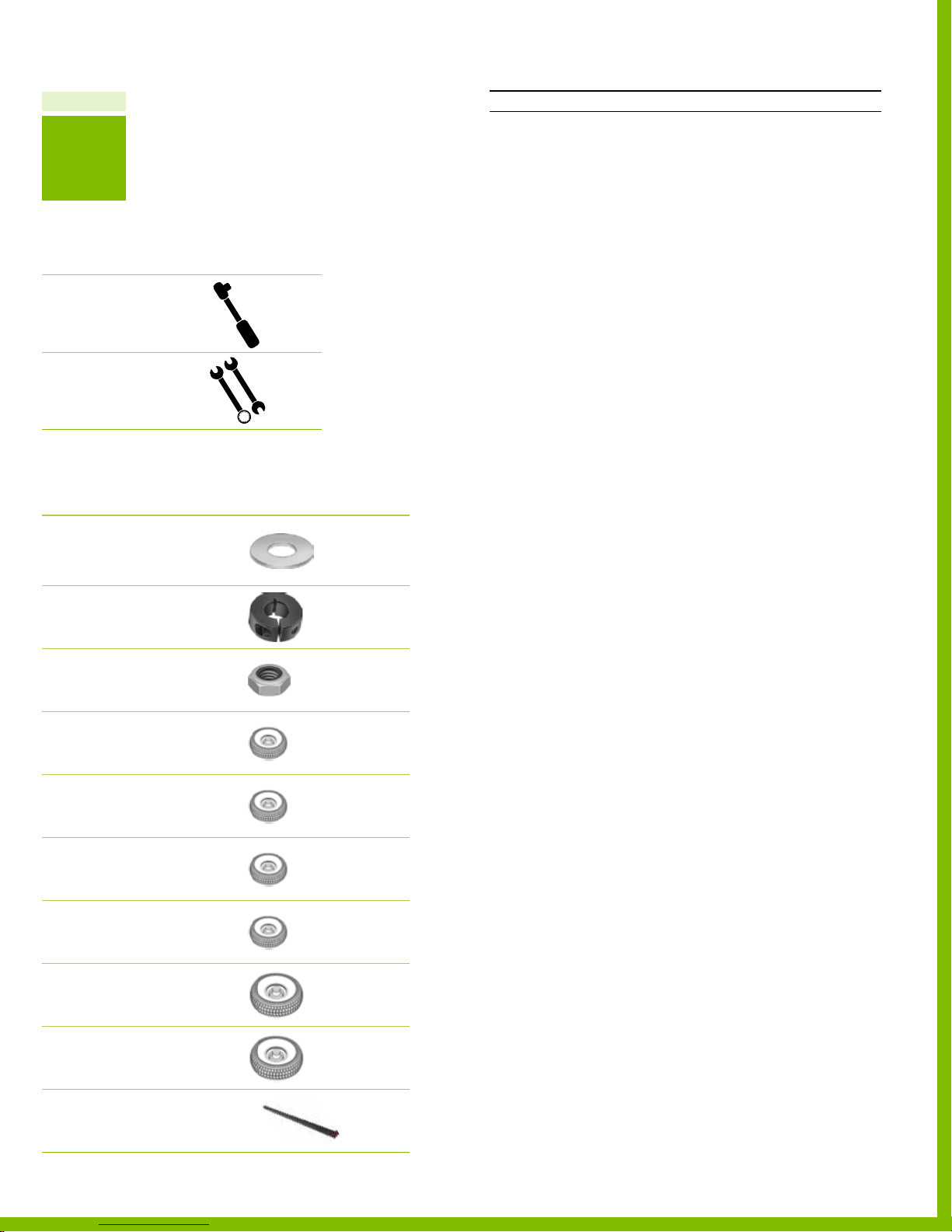
Chapter 10
8
PAR T
Recommended tools
DESCRIPTION REFERENCE
Socket Wrench
Wrench
Required hardware
№ DESCRIPTION REFERENCE
Flat Washer
5/16” ID, 7/8” OD
3 SINGLE WHEEL KIT PN 12 516
2 LIVE A XLE KIT PN 12516
2 Shaf t Collar
5/8” ID
PN 12540
2 Lock Nut
5/8"‑11
PN 12 50 6
1 Rear driven wheel
10”D
SINGLE WHEEL KIT PN 12 59 0
3 Undriven wheel
10” D
SINGLE WHEEL KIT PN 12 59 1
2 Rear driven wheel
10”D
LIVE A XLE KIT PN 125 9 0
2 Undriven wheel
10” D
LIVE A XLE KIT PN 125 91
1 Rear driven wheel
12” D
SINGLE WHEEL KIT PN 12 59 2
3 Undriven wheel
12” D
SINGLE WHEEL KIT PN 1259 3
1 Key
150718 PLYFL Y rev A_GoKart | A ug u st 7, 20 1 5 5:0 8 PM
3/16” square, 1”L
PN 12 53 9
Part 8 Install the wheel assemblies
INSTRUCTIONS
1. Mount the undriven wheels (the wheels with bearings)
by sliding them over the axles.
‒
SINGLE WHEEL KIT continue to step 2.
LIVE A XLE KIT continue to step 4.
‒
2. Mount 3 undriven wheels.
‒ 2 located on the front axles.
‒ 1 located on the back, left axle.
‒ Total of 3 locations.
SINGLE WHEEL KIT continue to step 5.
3.
4. Mount 2 undriven wheels.
‒ 2 located on the front axles.
‒ Total of 2 locations.
5. Secure the undriven wheels using lock nuts.
Hint To keep the wheels from rotating, place a
large slotted screwdriver into the heads of the front axle bolts.
6. Slide the shaft collar over drive shaft.
SINGLE WHEEL KIT continue to step 7.
‒
LIVE A XLE KIT continue to step 9.
‒
7. Install 1 shaft collar.
‒ 1 on the back, right drive shaft.
SINGLE WHEEL KIT continue to step 10.
8.
9. Install 2 shaft collars.
‒ 2 located on the rear drive shaft.
‒ Total of 2 locations.
10. Secure the shaft collar using an Allen wrench.
11. Mount the driven wheel (the wheels with the xed hub)
by sliding them over the drive shaft.
‒ Use the key to lock the driven wheel to the drive shaft.
SINGLE WHEEL KIT continue to step 12.
‒
LIVE A XLE KIT continue to step 14.
‒
12. Mount 1 driven wheel.
‒ 1 located on the back, right drive shaft.
‒ Total of 1 location.
SINGLE WHEEL KIT continue to step 15.
13.
14. Mount 2 driven wheels.
‒ Use the key to lock the driven wheel to the drive shaft.
‒ 2 located on the rear drive shaft.
‒ Total of 2 locations.
15. Secure the driven wheel to the drive shaft using
the set screws.
‒ Be sure the set screw aligns with the keyway.
16. Secure the axle to the driven wheel using the shaft collar.
‒ Use a socket wrench to tighten the locknut; while
holding the locknut on alternate side with wrench.
PlyFly Go‑Kart Instruction Guide • 2015 Release
57
Page 62
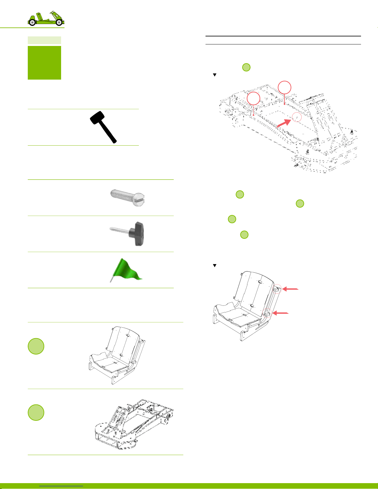
Chapter 10
9
PAR T
Recommended tools
DESCRIPTION REFERENCE
Dead blow Hammer
or mallet
Required hardware
№ DESCRIPTION REFERENCE
2 Fillister Head Screw
5/16”‑18, 3/4” L
PN 125 5 3
1 T‑Handle
Quick Release Pin
PN 125 4 2
1 Flag
Plyy ag
PN 125 3 5
Part 9 Install the seat assembly
INSTRUCTIONS
1. Place the Fillister head screws into the parts 41 & 42
located on
Note the location of the Fill ister head screws.
2. Secure the Fillister head screws to be ush with the
wooden surface of part 41.
3. Position
‒ Align the side slots located on
located on parts 41 & 42.
4. Slide
4
the way through slots.
5. To secure
through part 41 located on the right side of the go‑kart.
6. Insert the ag through holes located on the back right
side of Seat Assembly and the go‑kart frame.
Note the location of the a g hol es.
.
9
41
42
4
at the forward most position.
4
to the screw heads
backwards into position so that the pins slide all
4
in place, insert the T‑handle, pin side,
Required assemblies
DESCRIPTION REFERENCE
4
Seat
Assembly
PARTS 22‑33
9
Frame
Assembly
PARTS 21‑28
10 Putting the go‑kart together
58
150718 PLYFL Y rev A_GoKart | A ug u st 7, 20 1 5 5:0 8 PM
Page 63
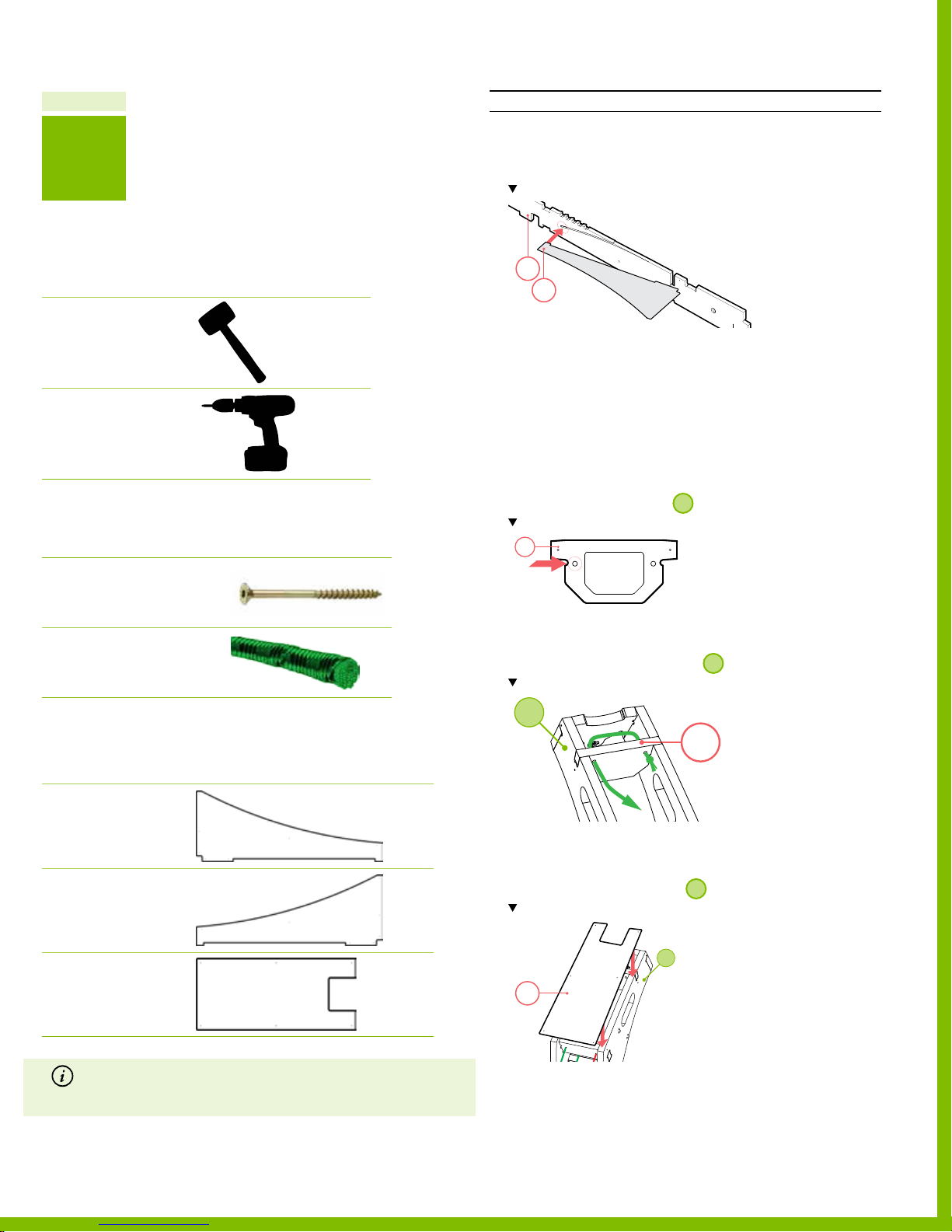
Chapter 10
10
STEP
Part 10 Install the fairings
INSTRUCTIONS
1. Place the front tab of part 53 into the slot located on
part 40.
Note the location of the tab on part 40.
Recommended tools
DESCRIPTION REFERENCE
Dead blow Hammer
or mallet
Electric Driver
Required hardware
№ DESCRIPTION REFERENCE
20 Spax Screw
1 #8, 1‑1/2” L
PN 12519
1 Green Elastic Cord
3/16” OD, 18” L
PN 12 517
40
53
2. Using the mallet, tap part 53 into the recess.
3. Secure part 53 to the assembly using screws.
‒ Use 7 screws.
‒ Total of 7 locations.
4. Repeat steps 1 through 3 on the opposite side using
par t 54.
5. Thread the green elastic cord, from the top through left
hole located in part 16 of
Note the part 16
16
.
2
6. Tie an overhand knot on the bottom side.
7. Thread the green elastic cord, from the top through right
side hole located in part 16 of
Note the location of part 16.
2
.
2
Required wooden parts
DESCRIPTION REFERENCE
Part 53
Fairing Left
PLYWOOD SHEET 4
Part 54
Fairing Right
PLYWOOD SHEET 4
Part 55
Fairing Front
PLYWOOD SHEET 4
Note If you received a 1/4” plywood sheet that is nished on one side
and intend to paint the fairings; reverse wooden par ts 53-55 (so the
unn ished side is facing out ward and ready to rece ive paint). For more
150718 PLYFL Y rev A_GoKart | A ug u st 7, 20 1 5 5:0 8 PM
information on Visual reference of the plywood sheets, see page 61.
16
8. Pull green elastic cord tight and tie overhand knot on
the underside.
9. Align part 55 to the front of
Note the location of the orientation of part 55.
55
10. Screw part 55 to the assembly using 6 screws.
‒ Use 6 screws.
‒ Total of 6 locations
FINISHED!! TIME TO RIDE!!
PlyFly Go‑Kart Instruction Guide • 2015 Release
.
2
2
59
Page 64

Master List
11
1 50 7 1 8 P LY F LY r e v A_E M | August 7, 2015 5:06 PM
60
Page 65
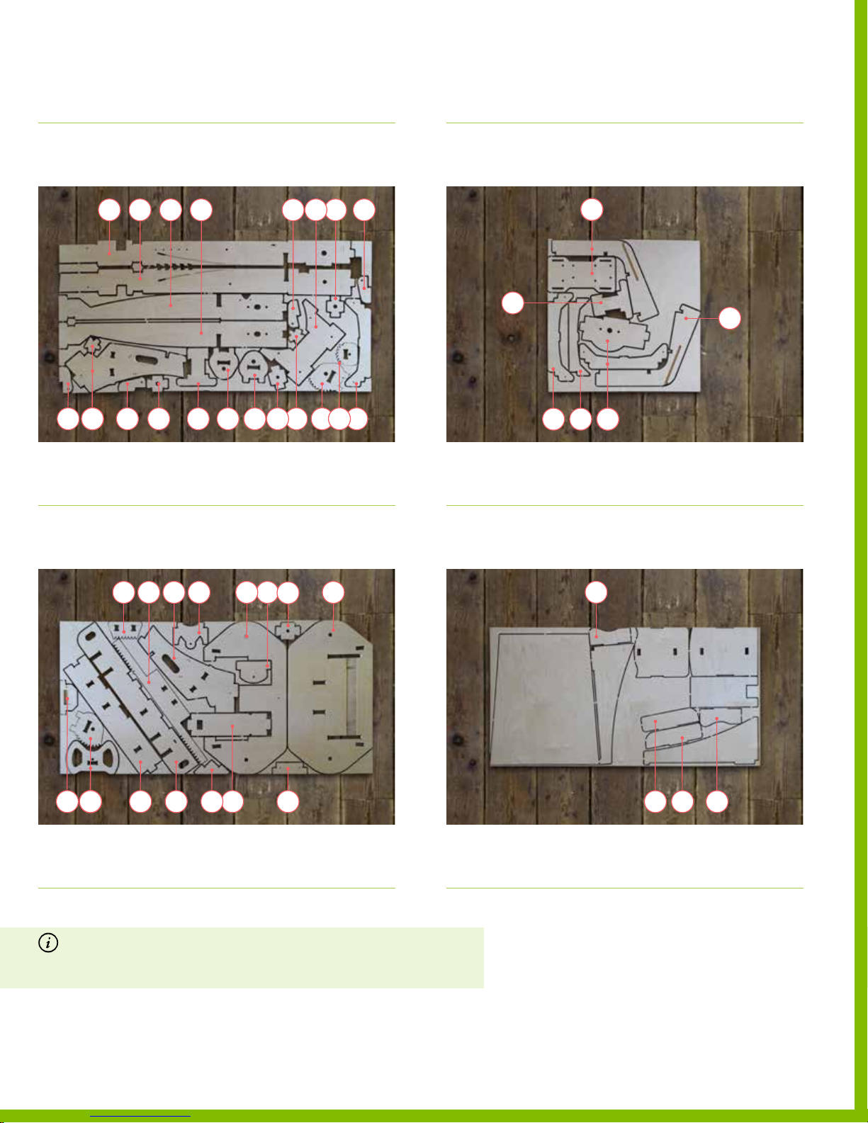
Visual reference of the plywood sheets
DESCRIPTION REFERENCE
Visual reference of the plywood sheets
DESCRIPTION REFERENCE
Sheet 1
3/4” Plywood Sheet
3736
‒ Parts 1, 3‑4
‒ Parts 6‑10
‒ Part 13
Sheet 2
3/4” Plywood Sheet
‒ Parts 20
‒ Parts 24
‒ Parts 34
38 39
10913 34
4941 40 43 42
3
61874 20
‒ Parts 36‑43
‒ Parts 49
24
Sheet 3
3/4” Plywood Sheet
35
‒ Parts 22‑23
‒ Parts 25‑27
Sheet 4
1/4” Plywood Sheet
22
50
252726
47
‒ Parts 35
‒ Part 47
23
‒ Parts 50
12 11 15 1814
46 5248
‒ Parts 2, 5
‒ Parts 11‑12
‒ Parts 14‑18
Note If you received a 1/4” plywood sheet that is nished on one side and you
intend to paint the Plyy go-kart seat or fairings; reverse wooden parts 28-33 and
parts 53-55 (so the unnished side is outward facing and ready to receive paint).
For a complete list of wooden par ts, go to “List of the wooden par ts” on page 62.
‒ Parts 20‑21
‒ Parts 44‑46
‒ Parts 48
45 44
171625521 19
‒ Parts 52
‒ Parts 28‑33
‒ Parts 51
31
302829
‒ Parts 53‑55
1 50 7 1 8 P LY F LY r e v A_E M | August 7, 2015 5:06 PM
PlyFly Go‑Kart Instruction Guide • 2015 Release
61
Page 66
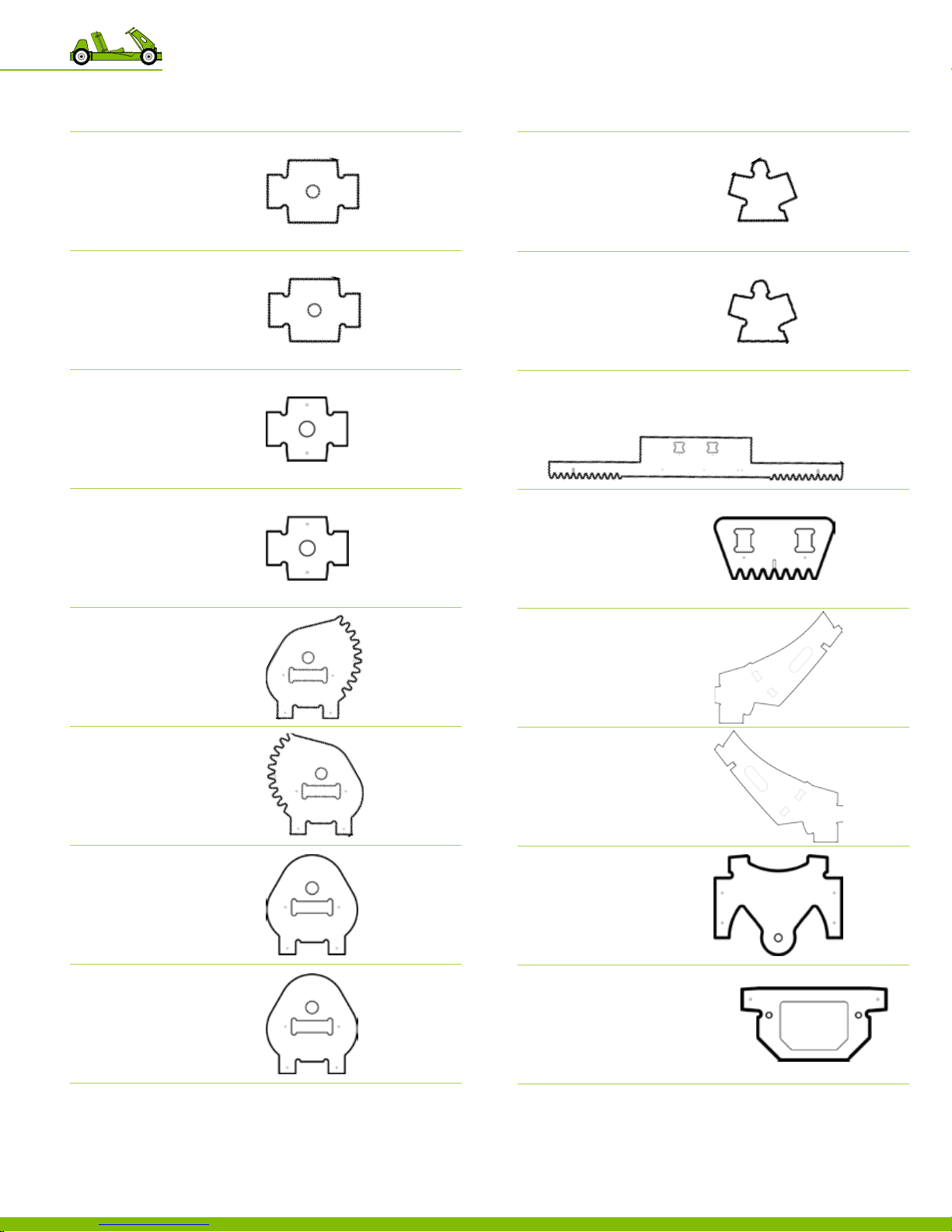
List of the wooden parts
DESCRIPTION
reference image
List of the wooden parts
DESCRIPTION
reference image
Part 1
Steering Spindle Outer Spacer
PLYWOOD SHEET 1
Part 2
Steering Spindle Outer Spacer
PLYWOOD SHEET 2
Part 3
Steering Spindle Inner Spacer
PLYWOOD SHEET 1
Part 4
Steering Spindle Inner Spacer
PLYWOOD SHEET 1
Part 9
Steering rack Bracket
PLYWOOD SHEET 1
Part 10
Steering rack Bracket
PLYWOOD SHEET 1
Part 11
Steering rack
PLYWOOD SHEET 2
Part 12
Steering rack Center Bracket
PLYWOOD SHEET 2
Part 5
Steering Spindle Bottom Left
PLYWOOD SHEET 2
Part 6
Steering Spindle Bottom Right
PLYWOOD SHEET 1
Part 7
Steering Spindle Top
PLYWOOD SHEET 1
Part 8
Steering Spindle Top
PLYWOOD SHEET 1
Part 13
Steering column Left
PLYWOOD SHEET 1
Part 14
Steering column Right
PLYWOOD SHEET 2
Part 15
Steering column Top
PLYWOOD SHEET 2
1 50 7 1 8 P LY F LY r e v A_E M | August 7, 2015 5:06 PM
Part 16
Steering column Phone Mount
PLYWOOD SHEET 2
11 Master List
62
Page 67
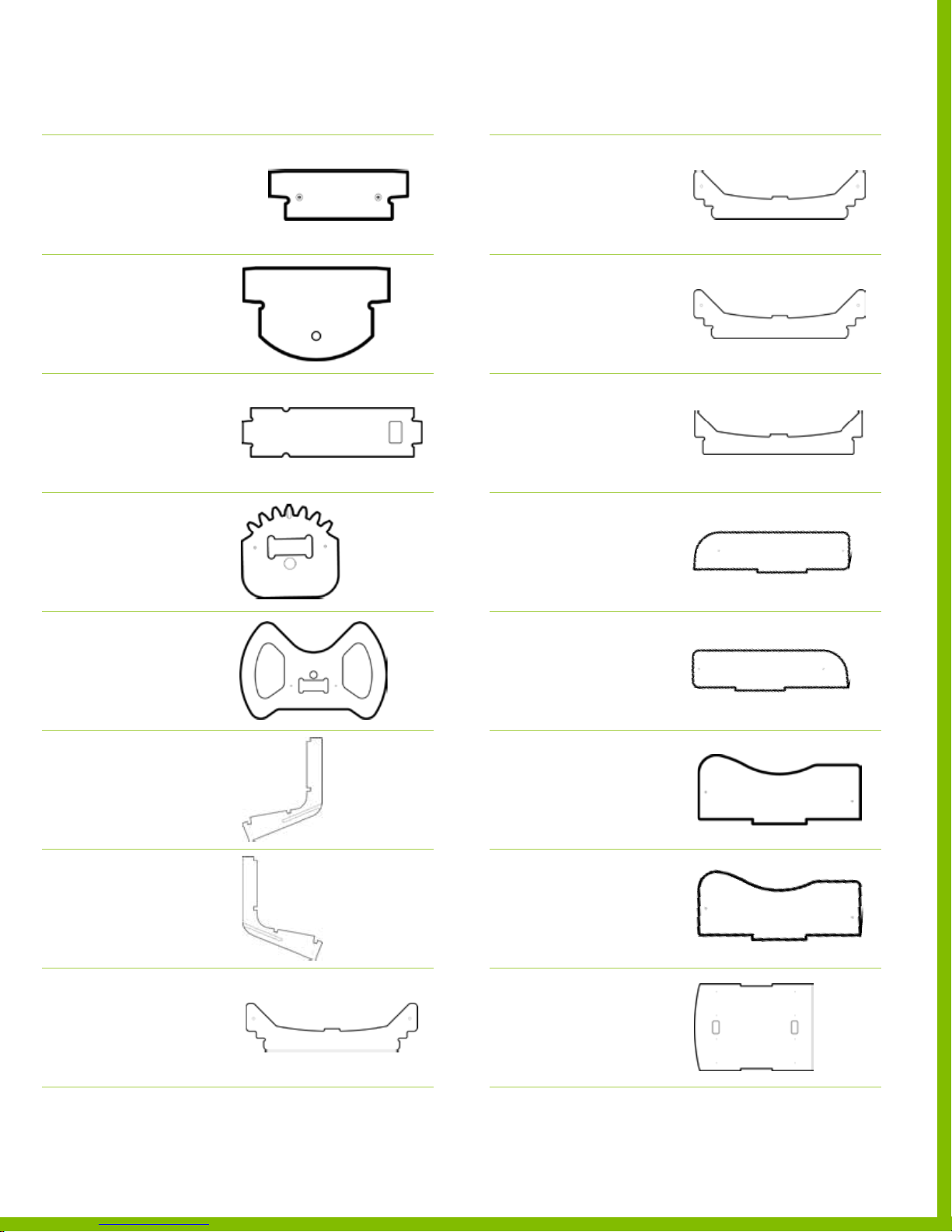
List of the wooden parts
DESCRIPTION
reference image
List of the wooden parts
DESCRIPTION
reference image
Part 17
Steering column Bracket
PLYWOOD SHEET 2
Part 18
Steering Pinion Mount
PLYWOOD SHEET 2
Part 19
Steering column Shaft
PLYWOOD SHEET 2
Part 20
Steering Pinion
PLYWOOD SHEET 1
Part 25
Seat Crossbar
PLYWOOD SHEET 3
Part 26
Seat Crossbar
PLYWOOD SHEET 3
Part 27
Seat Crossbar Bracket
PLYWOOD SHEET 3
Part 28
Seat Bolster Left
PLYWOOD SHEET 4
Part 21
Steering Wheel
PLYWOOD SHEET 2
Part 22
Seat Side Left
PLYWOOD SHEET 3
Part 23
Seat Side Right
‒ gas tank side
PLYWOOD SHEET 3
Part 24
Seat Crossbar
PLYWOOD SHEET 1
Part 29
Seat Bolster Right
PLYWOOD SHEET 4
Part 30
Seat Thigh Bolster Left
PLYWOOD SHEET 4
Part 31
Seat Thigh Bolster Right
PLYWOOD SHEET 4
Part 32
Seat Back
PLYWOOD SHEET 4
1 50 7 1 8 P LY F LY r e v A_E M | August 7, 2015 5:06 PM
PlyFly Go‑Kart Instruction Guide • 2015 Release
63
Page 68
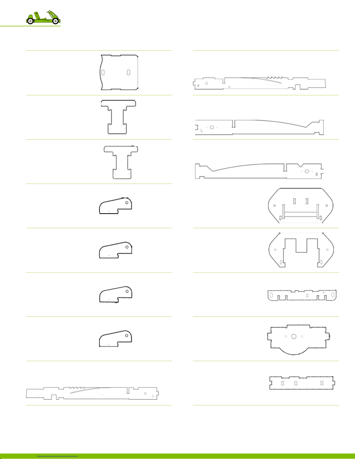
List of the wooden parts
DESCRIPTION
Part 33
Seat Bottom
PLYWOOD SHEET 4
Part 34
Brake Pedal
PLYWOOD SHEET 1
Part 35
Gas Pedal
PLYWOOD SHEET 3
reference image
List of the wooden parts
DESCRIPTION
Part 41
Frame Rail Inner Right
PLYWOOD SHEET 1
Part 42
Frame Rail Outer Left
PLYWOOD SHEET 1
Part 43
Frame Rail Outer Right
PLYWOOD SHEET 1
reference image
Part 36
Pedal Side
PLYWOOD SHEET 1
Part 37
Pedal Side
PLYWOOD SHEET 1
Part 38
Pedal Side
PLYWOOD SHEET 1
Part 39
Pedal Side
PLYWOOD SHEET 1
Part 40
Frame Rail Inner Lef t
PLYWOOD SHEET 1
Part 44
Frontend Bottom
PLYWOOD SHEET 2
Part 45
Fr o nte n d To p
PLYWOOD SHEET 2
Part 46
Frame Rail Bracket
PLYWOOD SHEET 2
Part 47
Sprocket Guard
PLYWOOD SHEET 3
1 50 7 1 8 P LY F LY r e v A_E M | August 7, 2015 5:06 PM
Part 48
Frame Rail Rear
PLYWOOD SHEET 2
11 Master List
64
Page 69
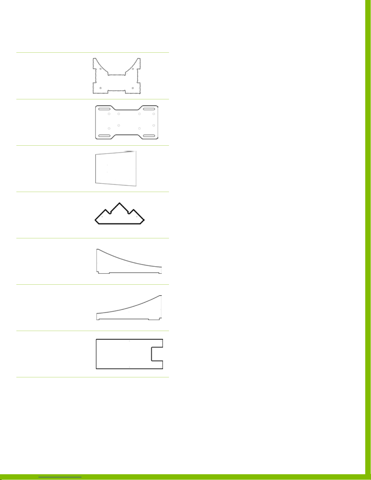
List of the wooden parts
DESCRIPTION
Part 49
Frame Rail Engine Mount
PLYWOOD SHEET 1
Part 50
Engine Mounting Plate
PLYWOOD SHEET 3
Part 51
Floor Panel
PLYWOOD SHEET 4
Part 52
Frame Gusset
PLYWOOD SHEET 2
reference image
Part 53
Fairing Left
PLYWOOD SHEET 4
Part 54
Fairing Right
PLYWOOD SHEET 4
Part 55
Fairing Front
PLYWOOD SHEET 4
1 50 7 1 8 P LY F LY r e v A_E M | August 7, 2015 5:06 PM
PlyFly Go‑Kart Instruction Guide • 2015 Release
65
Page 70
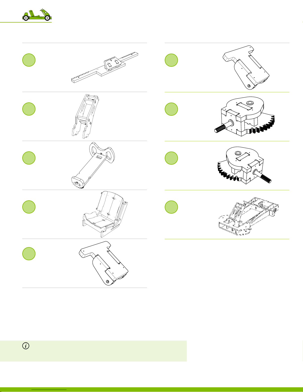
List of the wooden assemblies
DESCRIPTION REFERENCE
List of the wooden assemblies
DESCRIPTION REFERENCE
1
Steering rack
Assembly
Pa r t s 9 ‑12
2
Fixed steering column
Assembly
Pa r t s 13‑18
3
Steering column
Assembly
Par ts 19‑21
6
Brake Pedal
Assembly
Parts 35, 38‑39
7
Left Spindle
Assembly
Parts 1, 3, 5, 7
8
Right Spindle
Assembly
Parts 2, 4, 6, 8
4
Seat
Assembly
Parts 22‑33
5
Gas Pedal
Assembly
Parts 34, 36‑37
Note If you received a 1/4” plywood sheet that is nished on one side and you
intend to paint the Plyy go-kart seat or fairings; reverse wooden parts 28-33 and
parts 53-55 (so the unnished side is outward facing and ready to receive paint). For
a complete list of wooden parts, go to “List of the wooden parts” on page 62.
9
Frame
Assembly
Par ts 21‑2 8
1 50 7 1 8 P LY F LY r e v A_E M | August 7, 2015 5:06 PM
11 Master List
66
Page 71
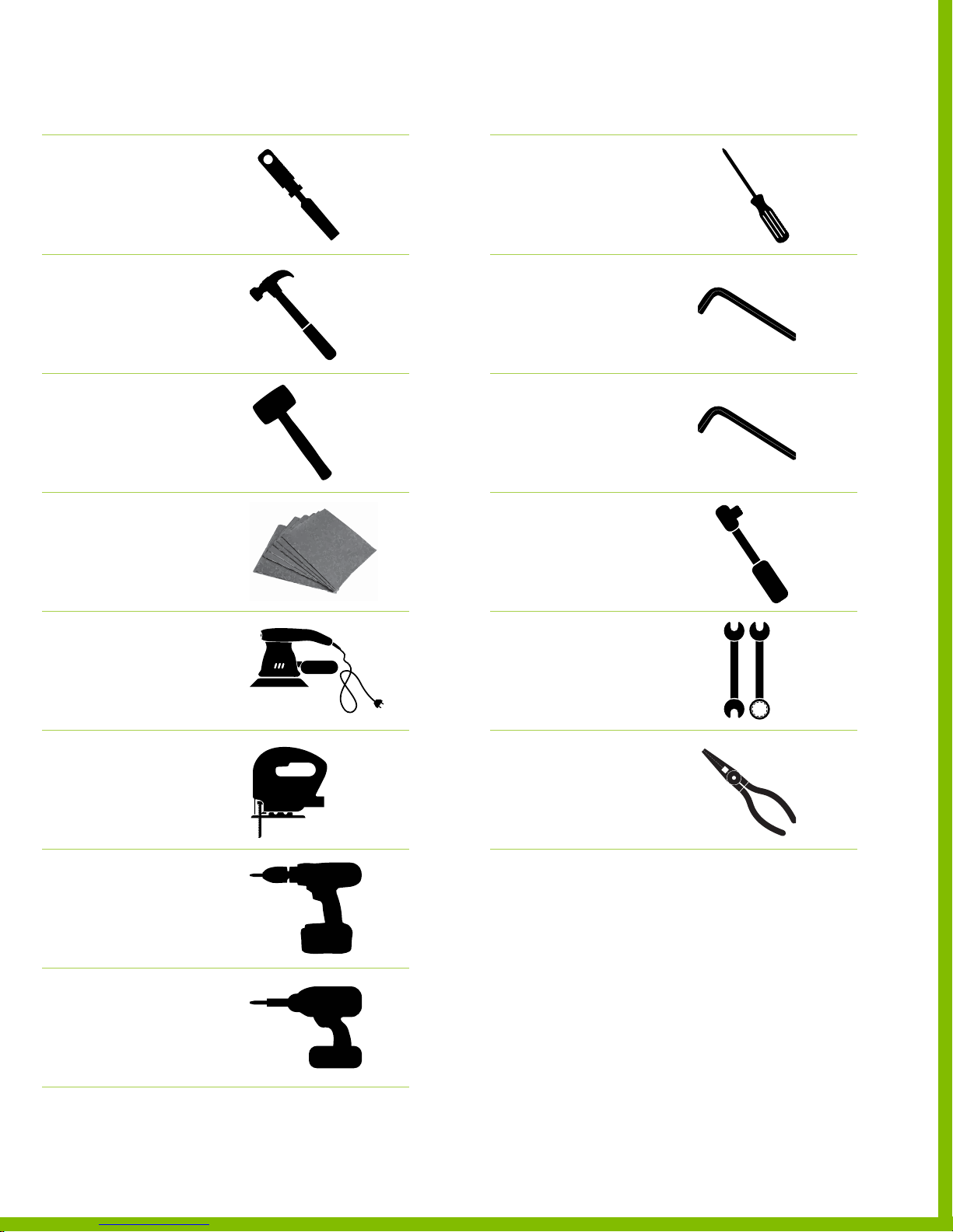
List of the tools needed
DESCRIPTION REFERENCE IMAGE
List of the tools needed
DESCRIPTION REFERENCE IMAGE
Chisel
Hammer
Dead blow Hammer
or mallet
Sandpaper
Screwdriver
Allen Wrench
or ratcheting allen wrench
Metric Allen Wrench
included with mounted bearing
Socket Wrench
Orbital Sander
(optional)
Jigsaw or
Reciprocating Saw
(optional)
Electric Driver
Impact Driver
(optional)
Wrench
Needle Nose Pliers
1 50 7 1 8 P LY F LY r e v A_E M | August 7, 2015 5:06 PM
PlyFly Go‑Kart Instruction Guide • 2015 Release
67
Page 72
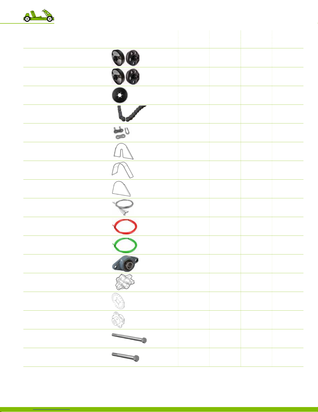
List of loose contents
KIT DESCRIPTION 10” WHEELS 10” WHEELS 12” WHEELS 10” WHEELS 12” WHEELS
№
12576
Clutch
#35 Chain, 11 Tooth Pulley for 5/8” D
2.5 HP MODEL
1257 7
Clutch
#35 Chain, 12 Tooth Pulley for 3/4” D
4.0 HP MODEL
1252 2
Sprocket
#35 Chain, 60 Tooth, 5/8” D bore
1252 4
Roller Chain
#35 Chain, 29‑5/8” L
12534
Master Chain Link
#35 Roller Chain connector
Part 56
120 05
Clutch Guard Side
Engine Mounting Plate
Part 57
120 06
Clutch Guard Top
Top C o ver
Part 58
120 07
Clutch Guard Cover
Outside Cover
2.5 HP 4.0 HP 4.0 HP 4 .0 HP 4.0 HP
SINGLE WHEEL SINGLE WHEEL SINGLE WHEEL LIVE AXLE LIVE AXLE
1
―
― ― ― ―
1 1 1 1
1 1 1 1 1
1 1 1 1 1
1 1 1 1 1
1 1 1 1 1
1 1 1 1 1
1 1 1 1 1
12525
Control Cable
1/16” D, throttle & brake control cable
1252 7
Red Throttle Cable
Brake conduit, 5’ L
1252 8
Green Throttle Cable
Gas conduit, 6’ L
1252 1
VXB Mounted Bearing
5/8” ID
12531
Brake Caliper
12532
Brake Disc
12533
Brake Disc Hub
12502
Long Hex Bolt
Grade 5, 5/8”‑11, 11” L
SINGLE WHEEL KIT
12503
Shor t Hex Bolt
Grade 5, 5/8”‑11, 6.5” L
2 2 2 2 2
1 1 1 1 1
1 1 1 1 1
3 3 3 3 3
1 1 1 1 1
1 1 1 1 1
1 1 1 1 1
1 1 1
― ―
4 4 4 4 4
1 50 7 1 8 P LY F LY r e v A_E M | August 7, 2015 5:06 PM
11 Master List
68
Page 73
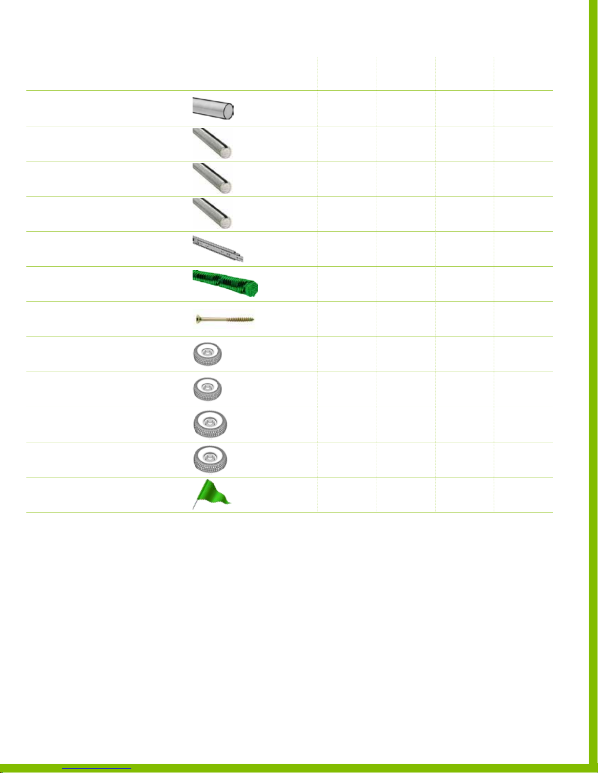
List of loose contents
KIT DESCRIPTION 10” WHEELS 10” WHEELS 12” WHEELS 10” WHEELS 12” WHEELS
№
12507
Precision Rod
1/4” D, 18” L
12580
Drive Shaft
Steel, Keyed, 5/8” D, 18” L
SINGLE WHEEL KIT
12581
Drive Shaft
Steel, Keyed, 5/8” D, 33” L
LIVE A XLE KIT – 10” WHEELS
12582
Drive Shaft
Steel, Keyed, 5/8” D, 36” L
LIVE A XLE KIT – 12” WHEELS
12508
Drawer Slide
Hardware included, 10” L
125 17
Green Elastic Cord
3/16” OD, 18” L
12519
Spax Screw
1 Box, #8, 1‑1/2” L
2.5 HP 4.0 HP 4.0 HP 4 .0 HP 4.0 HP
SINGLE WHEEL SINGLE WHEEL SINGLE WHEEL LIVE AXLE LIVE AXLE
1 1 1 1 1
1 1 1
― ― ―
― ― ― ―
― ―
1
1 1 1 1 1
1 1 1 1 1
1 1 1 1 1
―
1
12590
10” D Wheels
Rear driven wheel
12591
10” D Wheels
Undriven wheel
12592
12” D Wheels
Rear driven wheel
12593
12” D Wheels
Undriven wheel
12535
Flatworks Flag
Plyy safety ag
1 1
3 3
― ―
― ―
―
―
1
3
2
2
―
―
―
―
2
2
1 1 1 1 1
1 50 7 1 8 P LY F LY r e v A_E M | August 7, 2015 5:06 PM
PlyFly Go‑Kart Instruction Guide • 2015 Release
69
Page 74
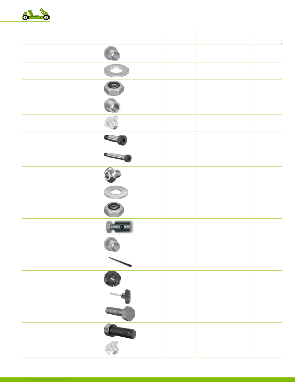
List of the packaged contents
KIT DESCRIPTION 10” WHEELS 10” WHEELS 12” WHEELS 10” WHEELS 12” WHEELS
№
12504
Large Metal Bushing
Flanged, 3/4” OD, 5/8” ID
12505
Flat Washer
5/8” ID, 1‑3/8” OD
12506
Lock Nut
5/8” ID
12509
Plastic Bushing
Flanged, 1/4” ID, 3/8” OD
12510
Small Tee Nut
Zinc Plated, 5/16”‑18
12513
Shor t Shoulder Screw
5/16”‑18, 3/8” D, 1.00” L,
12514
Long Shoulder Screw
5/16”‑18, 3/8” D, 2.25” L
2.5 HP 4. 0 HP 4.0 HP 4 .0 HP 4 .0 HP
SINGLE WHEEL SINGLE WHEEL SINGLE WHEEL LIVE AXLE LIVE AXLE
11
11 11 10
4 4 4 4 4
5 5 5 4 4
4 4 4 4 4
12 12 12 12 12
1 1 1 1 1
1 1 1 1 1
10
12515
Button Socket Head Cap Screw
Zinc Plated, Steel, M8, 12mm L
12516
Flat Washer
5/16” ID, 7/8” OD
1252 0
Thin Nut
Grade 5, 5/16”‑24
12537
Throttle Cable Clamp
12538
Small Metal Bushing
Flanged 3/8” ID, 1/4” L
12539
Key
3/16” square, 1”L
12540
Shaf t Collar
5/8” ID
12542
T‑Handle Pin
Quick Release Pin
12543
Hex head cap screw
5/16”‑18, 1.25 L
4.0 HP MODEL
5 5 5 5 5
15 15 15 15 15
4 4 4 4 4
1 1 1 1 1
4 4 4 4 4
3 3 3 4 4
1 1 1 2 4
1 1 1 1 1
8 8 8 8 8
1 50 7 1 8 P LY F LY r e v A_E M | August 7, 2015 5:06 PM
12544
Socket Head Cap Screw
Black Oxide Alloy Steel, 3/8”‑16, 1.25 L
12545
Large Tee Nut
Zinc Plated, 3/8”‑16
11 Master List
70
6 6 6 6 6
6 6 6 6 6
Page 75
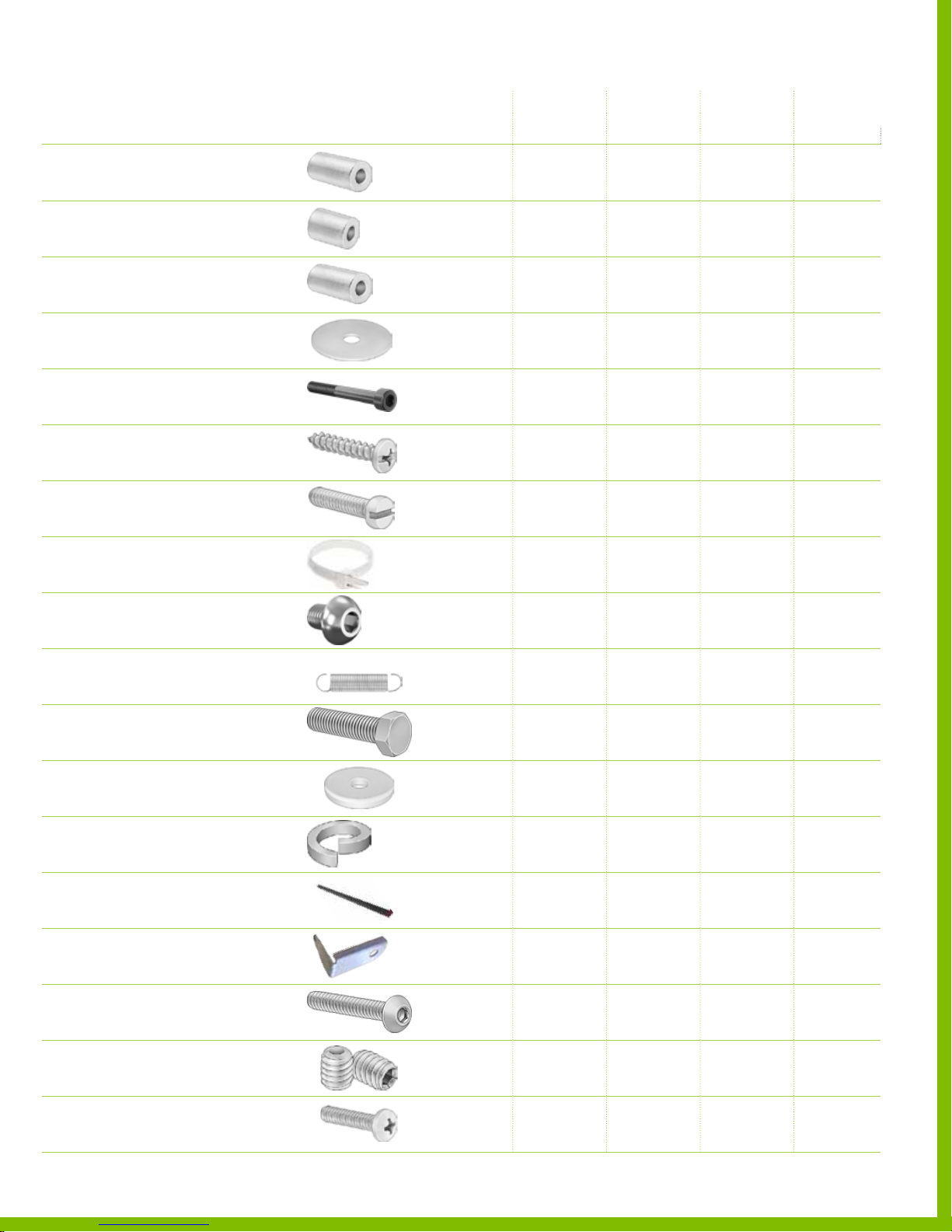
List of the packaged contents
KIT DESCRIPTION 10” WHEELS 10” WHEELS 12” WHEELS 10” WHEELS 12” WHEELS
№
12546
Nylon Spacer
3/4” OD, 3/8” ID, 1‑1/4” L
12547
Shor t Aluminum Spacer
1/2” OD, 1/4” ID, 7/8” L
12548
Long Aluminum Spacer
1/2” OD, 1/4” ID, 1‑1/16” L
12549
Oversized Flat Washer
Zinc, M6
12550
Socket Head Cap Screw
Black oxide, M6, 55mm L
12551
Sheetmetal Screw
Galvanized, #6
12553
Fillister Head Screw
5/16”‑18, 3/4” L
2.5 HP 4. 0 HP 4.0 HP 4 .0 HP 4 .0 HP
SINGLE WHEEL SINGLE WHEEL SINGLE WHEEL LIVE AXLE LIVE AXLE
1 1 1 1 1
1 1 1 1 1
1 1 1 1 1
2 2 2 2 2
2 2 2 2 2
8 8 8 8 8
2 2 2 2 2
12558
Zip Tie
10lb Nylon, White, 7/8” D, 4” L
12559
Button Socket Head Cap Screw
Zinc Plated, Steel, 5/16”‑24, 1/2” L
12560
Extension Spring
Black‑Oxide, Precision
12554
Hex Cap Screw
1/4”‑20, 1” L
2.5 HP MODEL
12555
Fender washer
5/16” ID, 1‑1/8” OD
12556
Lock washer
5/16” ID
12557
Clutch Key
3/16”, 1/2” L
12561
Throttle Return Clip
4.0 HP MODEL
12562
Button Head Cap Screw
5/16”‑24, 3/4” L
6 6 6 6 6
4 4 4 4 4
1 1 1 1 1
1
― ― ― ―
1 1 1 1 1
1 1 1 1 1
1 1 1 1 1
―
―
1 1 1 1
1 1 1 1
12563
Set Screw
Clutch
125 64
1 50 7 1 8 P LY F LY r e v A_E M | August 7, 2015 5:06 PM
Pan head
M6, 12 mm L
4.0 HP MODEL
2 2 2 2 2
―
1 1 1 1
PlyFly Go‑Kart Instruction Guide • 2015 Release
71
Page 76

12
Legal
1 5 0 7 1 8 P L Y F L Y r e v A _ L e g a l | August 5, 2015 10:38 PM
72
Page 77

Legal
Assumption of Risk, Waiver and Release of Liabilities and Indemnity
Agreement
I, the undersigned, on behalf of myself, (and, if applicable, my minor
child or ward listed below), as well as my spouse, heirs, estate, insurers
and assigns (all collectively hereinaf ter referred to as “I” or “me” or “my”,
as the case may be), in consideration of being permitted to use and
operate (whether via a test drive prior to purchase or otherwise) the go
kart equipment of The Flatworks, LLC, a Rhode Island Limited Liability
Company (hereinafter “Flatworks”), at its premises and facilities located
at 11 Waites Wharf, Newport, Rhode Island or at any other locale, and for
other good and valuable consideration, do hereby covenant and agree as
follows:
1. I fully understand and acknowledge that I, like all potential customers of
Flatworks and others desiring to test drive or other wise use and operate
its go-kart equi pme nt, as a condition of such use and operation, must rst:
a) read, understa nd, and agree to this Assumption of Risk, Waiver and
Release of Liabiliti es and Indemnity Agre ement (the “Agre eme nt” ); and b)
read, understand, adhere to, and abide by the safet y rules and instructions
of Flatworks related to the use a nd operation of its go‑kart equipment.
2. I fully understand and acknowledge that: a) using and operating a
motorized go‑kart is an inherently dangerous activit y and that participation
in this activity involves risks of damage to or loss of my property or the
proper ty of others and risks of bodily injury to me or others, including
injuries such as bruises, lacerations, sprains, fractures and, in extreme
cases, disabili ty, paralysis and death; b) such danger s and risks may b e
caused, in whole or in par t, by my own actions or inactions, the actions
or inactions of others, the condition of the go‑kart equipment and the
condition and the layout of the facilities on which they are used, and/or
the negligence of others, including the Protected and Released Parties (as
dened below); and c) there may b e other dangers an d risks assoc iate d
with this activity which at this time are unknown or that are not readily
foreseeable by me or others.
3. I fully understand and ack nowledge the demands of this inherently
dangerous and risky activity relative to my personal knowledge, experience,
skills, aptitude and abilities, as well as my current physical and medical
conditi on and level of tness, and nevertheless knowingly and voluntarily
accept and assume such dangers and risks, and further assume f ull
responsibility for any and all liabilities, losses or damages, including
any direct or consequential damages, resulting from or related to my
participation in this activity, including, but not limited to: any and all damage
to or loss of my proper ty or the prop erty of others; pe rso nal i njuries to me
or oth ers of any t ype, inc luding disability a nd death; a nd any leg al fe es,
costs or other expenses related to such damages and/or injuries, expressly
including, but not limited to, those alleged to be caused, in whole or in part,
by the neglige nce of the Protected a nd Re leased Parties (as dene d below).
4. I hereby agree to waive, re lease, discharge and covenant not to sue
Flatworks or any other person or entity associated or aliated with these
entities, including, but not limited to, their owners, shareholders, directors,
ocers, members, partners, employees, volunteers, agents, subsidiaries,
related and aliated entities, and succe ssors an d assign s (all hereinafte r
referred to as the “Protected and Released Parties”) from liability for any
and all claims, suits, demands, liabilities, losses or damages a rising from
or relating to my use and operation of Flatworks’ go‑kar t equipment, my
participation in any related activities, and my pre sence on the premises
and facilities of the Protected and Released Parties. This waiver, release,
discharge and covenant not to sue applies, but is not limited to, any and
all liabilities, losses or damages, including any direct or consequential
damages, resulting from or related to my participation in this activity,
including, but not limited to: any and all damage to or loss of my property
or the proper ty of others; personal inju rie s to me or others of any t ype,
includi ng di sab ili ty and de ath; and any legal fees, costs or other expenses
related to such damages and/or injuries, expressly including, but not limited
to, those alleged to be c aused, in whole or in part, by the negligence of the
Protected and Released Parties.
5. If, despite my aforesaid express assumption of risk, and my aforesaid
express waiver, release, discharge and covena nt not to sue, I, or anyone
acting on my behalf, brings a claim or suit, or takes any other action,
against any of the Prote cted and Released Parties for any and all liabilities,
losses or damages, including any direct or consequential damages,
resulting from or related to my participation in this activit y, including, but not
1 5 0 7 1 8 P L Y F L Y r e v A _ L e g a l | August 5, 2015 10:38 PM
limited to: any and all damage to or loss of my propert y or the property of
othe rs; personal inju rie s to me or others of any t ype, including disabili ty and
death; and any legal fees, costs or other expenses related to suc h damage s
and/or injuries, expressly including, but not limited to, those alleged to
be caused, in whole or in par t, by the negligence of the Protected and
Released Par ties, I, for myself and for anyone acting on my behalf, further
agree to hold harmless, defend, and indemnify the Protected and Released
Parties from any such claims, suits, actions, liabilities, losses, damages,
fees, costs or expe nses.
6. In the event of a medical emergency, I hereby authorize Flatworks and
any other Protected and Released Par ties to, if deemed necessary in their
discretion, to admi nister emerg enc y rs t aid, CPR, and use an A ED, and
to secure emergency medical care or transportation (i.e., EMS). I agree to
assume all costs of such emergency medical care and transportation.
7. I acknowledge that this Agreement constitutes the entire agreement
by and among me and the Protected and Released Parties pertaining
to the subject matter hereof and supersedes all prior agreements and
understandings pertaining thereto, and agree that this Agreement may not
be changed, modi ed or amended in whole or in part except in writing,
signed by all of the partie s hereto.
8. I agree that this Agreement and the rights of the par ties hereunder shall
be interpreted in accordance with the laws of the State of Rhode Island,
as broadly and inclusively as permitte d under such laws, a nd all rights and
remedies shall be governed by such laws without regard to principles of
conict of laws. I furth er ag ree that if any portion of this Agreement is held
invalid, the balance shall, notwithstanding, continue in f ull legal force and
eect.
9. I agree that if any disputes or controversies shall arise from this Agreement
or otherwise in connection with my use and operation of Flatworks’ go‑kart
equipment, my par ticipation in any related activities, or my presence on
the premises and facilities of the Protected and Released Par ties, I shall
rst engage in good faith eorts to mediate such dispute. Should the
issue not be resolved by mediation, I further agree that all such disputes or
controversies shall be submitted to binding arbitration in accordance with
the Commercial Arbitration Rules of the American Arbitration Association
then in ee ct.
10. I hereby acknowledge, by signing below and by writing my initials in
the margin of all of the pages, that I have read this Agreement and fully
understand all of its terms and conditions. I understand that I am giving up
substantial legal rights, including rights that I may other wise have to sue for
damages in the event of my death, or injur y or loss occasioned by my use
of the go‑kart equipme nt of Flatworks. I acknowledge that I am signing
this Agreement freely and voluntarily, and intend by my signature, that this
Agreement constitute a complete and unconditional waiver, release, and
discharge of the Protected and Released Par ties from any and all manner of
claims, suits, actions, liabilities, losses, damages, fees, costs or expenses
arising from or related to the inherent risks of this activity, to the greatest
extent allowed by laws of the State of Rhode Island.
PlyFly Go‑Kart Instruction Guide • 2015 Release
73
Page 78

Terms &
13
Conditions
150718 PLYFLY rev A_Terms & Conditions | August 5, 2015 10:38 PM
74
Page 79

THE FLATWORKS, LLC
Terms & Conditions of Purchase and Use
THE FOLLOWING TERMS AND CONDITIONS APPLY TO ALL PRODUCTS
DESIGNED, MANUFACTURED AND SOLD BY THE FL ATWORKS,
LLC. THESE TERMS AND CONDITIONS INCLUDE PROVISION WHICH
ALLOCATE THE RISKS ASSOCIATED WITH THE USE OF THE PRODUCTS
AND LIMIT MY LEGAL RIGHTS TO RECOVER DAMAGES IN THE EVENT
OF INJURY OR LOSS OCCASIONED BY SUCH USE, INCLUDING
DISCLAIMERS, EXCULPATORY PROVISIONS (ASSUMPTIONS OF
RISK AND RELEASES), WAIVERS, INDEMNIFICATION PROVISIONS,
LIMITATIONS OF LIABILITY, LIMITED WARRANTIES, A COVENANT NOT
TO SUE, AN ABBREVIATED LIMITATIONS PERIOD FOR CLAIMS, AND AN
ARBITRATION PROVISION.
1. Denitions. As used herein, the following terms shall have the following
meanings:
a) “Flatworks”, shall mean The Flatworks, LLC, a Rhode Island Limited
Liability Co mpany and any and all of i ts aliates, subsidi ar ie s, ass oc ia tes,
owne rs, m emb ers, ocers, agents, employees, and volu nteers, and its
successors and assigns.
b) “Original Purchaser” shall me an the person to whom the Product was
originally sold as evidenced by the sales invoic e from Flatworks.
c) “Products” shall mean all products and related accessories designed,
manufactured and sold by Flatworks.
d) “User” shall mean the purchaser and/or the end user of any Product.
2. Acknowledgement of High Risk Activity. Products sold by Flatworks
include motorized go‑karts and related accessories. User hereby
acknowledge s that: a) using and operating a motorized go‑kart is an
inhere ntly dangerous activity and that participation in this activity invol ves
risks of damage to or loss of my property or the property of others and
risks of bodily injury to himself, herself, or others, including injuries such
as bruises, lacerations, sprains, fractures and, in extreme cases, disability,
paralys is and death; b) such dangers a nd risks may be caus ed, in whole
or in par t, by User’s own actions or inactions, the actions or inactions of
others, the condition of the go‑kart equipment and the condition and the
layout of the facilities on which they are used, and/or the neglige nce of
othe rs; and c) there may be other dang ers and risks associated with this
activity which at this time are unk nown or that are not readily foreseeable by
User or others.
3. Assumption of Risk. User fully understands and acknowledges the
dangers and risks involved with the use of the Products relative to his or her
personal knowledge, experience, skills, aptitude and abilities, as well as his
or he r physical and medica l con dition and level of tne ss, a nd ne ver the les s
knowingly and voluntarily accepts and assumes such dangers and risks,
and fur ther assumes full responsibility for any and all liabilities, losses or
damages, including any direct or consequential damages, resulting from or
related to his or her use of the Products, including, but not limited to: any
and all da mage to or loss of his o r her prop erty or the prope rt y of others;
personal injuries to User or others of any type, including disability and
death; and any legal fees, costs or other expenses related to suc h damage s
and/or injuries, expressly including, but not limited to, those alleged to
be caused, in whole or in par t, by equipment malfunction from whatever
cause, or any other negligence or fault of Flatworks.
4. Release and Waiver of Liability, Covenant Not to Sue. Other than the
liability assumed under the limited warrant y set for th herein below, which
liabili ty is conned to the repa ir or repl ace ment of its Prod ucts under li mite d
circumstance s, User he reby waives, releases, discharges and covenants
not to sue Flatworks from liability for any and all claims, suits, demands,
liabilities, losses or damages arising from or relating to his or her use of the
Products. This waiver, release, discharge and covenant not to sue applies,
but is not limited to, any and all liabilities, losses or damages, including any
direct or consequential damages, resulting from or related to the use of
the Products, including, but not limited to: any and all damag e to or loss of
his or her property or the prope rt y of others; per sonal injuries to the User
or oth ers of any t ype, inc luding disability a nd death; a nd any leg al fe es,
costs or other expenses related to such damages and/or injuries, expressly
including, but not limited to, those alleged to be caused, in whole or in part,
by equipment malfunction from whatever cause, or any other negligence or
150718 PLYFLY rev A_Terms & Conditions | August 5, 2015 10:38 PM
fault of Flatworks.
5. Indemnication. In the event that User, or anyone acting on his or her
behalf, brings a claim or suit, or takes any other action, against any
Flatworks for any liabilities, losses or damages, including any direct or
consequential damages, resulting from or related to his or her use of the
Products, including, but not limited to: any and all damage to or loss of my
prop er ty or the propert y of others; person al injur ies to User or others of
any t ype, includi ng di sab ility and death; and any legal fees, costs or other
expenses relate d to such damages and/or injuries, expressly including, but
not limited to, those alleged to be caused, in whole or in par t, by equipment
malfunction from whatever cause, or any other negligence or fault of
Flatworks, User, for himself or herself, and for anyone acting on his or her
behalf, further agree to hold harmless, defend, and indemnify Flatworks
from any such claims, suits, actions, liabilities, losses, damage s, fees, costs
or expenses.
6. Limited Replacement Warranty. Flatworks warrants to any Original
Purchaser that the Products shall to be free from defects in materials and
workmanship for a period of one‑hundred eighty (180) days from the date of
purchase, provided that they have not been subject to apparent accident,
alteration, abuse, neglect or misuse. Flatwork’s sole liability under this
warranty is limited to the repair or replacement of Products that are
returned within this warranty period.
THE ABOVE STATED LIMITED WARRANT Y IS IN LIEU OF ALL OTHER
WARRANTIES, EXPRESSED OR IMPLIED, INCLUDING THE WARRANTIES
OF MERCHANTABILITY AND FITNESS FOR A PARTICUL AR PURPOSE.
FLATWORKS NEITHER ASSUMES OR AUTHORIZES ANY OTHER
PERSON OR ENTITY TO ASSUME FOR IT, ANY OTHER LIABILIT Y
IN CONNECTION WITH THE DESIGN, MANUFACTURE OR SALE OF
ITS PRODUCTS, WHETHER FROM ITS WEBSITES, CATALOGS OR
OTHERWISE. THE LIMITED WARRANT Y SHALL NOT APPLY TO ANY
PRODUCT WHICH HAS BEEN SUBJECT TO ACCIDENT, NEGLECT,
ALTERATION, ABUSE OR MISUSE.
7. General Disclaimers. All Original Purchasers, as a condition of purchase,
agree to be bound by the following terms and conditions:
a) Inspection Prior to Use. All Products must be inspected upon delivery
for use to ensure that they have not been damaged in shipment or
otherwise. If any Product is damaged, such Product should not be
used and should be promptly returned to Flatworks for inspection,
replacement or repair, as the case may be.
b) Use of Products. Prior to the use and operation of any Product, the
Original Purchaser must read, understand, adhere to, and abide by
any instr uctions, manuals, directions and safet y rules related to the
Product, including, without limitation, those related to the assembly, use,
operation, and maintenance of the Product. Flatworks shall have no
responsibility whatsoever for the misuse or unauthorized and improper
use of its Products.
c) Duty to Inform O thers an d Ind emnicatio n. Prior to allowing othe rs to
use any Product, the Original Purchaser must require that such person
(or his or he r legal guardian, if a minor) reads, understands and agrees to
adhere to and abide by these Terms and Conditions and any instructions,
manuals, directions and safety rules re lated to the Product. The Original
Purchaser fur ther agrees, for himself or herself, and for anyone acting
on his or her behalf, to hold harmless, defend, and indemnify Flatworks
from any claims, suits, actions, liabilities, losses, damages, fees, costs or
expenses arising out of such person’s use of any Product.
8. Applicable Law. These Terms and Conditions and the rights of all aected
parties here under shall be interpreted in accordance with the laws of the
State of Rhode Island, as broadly and inclusively as permitted under such
laws, and all rights and remedies shall be governed by such laws without
regard to principles of conict of laws. If any por tion of these Terms
and Conditions shall be held invalid, the balance shall, not withstanding,
continue in full legal forc e and eect.
9. Resolution of Disputes. Any dispute, claim or controversy arising out of or
in connection with the purchase or use of the Products shall be resolved
by means of binding arbitration held within the State of Rhode Island
in accordance with the Commercial Arbitration Rules of the American
Arbitra tion Associatio n the n in eect. Any demand for arbitration must
be commenced within one (1) year after the dispute, claim or controversy
arises.
PlyFly Go‑Kart Instruction Guide • 2015 Release
75
 Loading...