

Page 1

Flat Vision Products Ltd
User Manual for
IPPM-15
Flat Vision Products Ltd
www.flatvision.co.uk
Page 2

1. Table of Content
1. Table of Content
2. Introduction
2. 1 Overview Page.2
2. 2 Features Page.2
2. 3 Product package Page.2
2. 4 Important safety Instructions Page.3
2. 5 Structure Diagram Page.4
2. 6 Dimension Diagram Page.5
3. Using the System
3. 1 Power LED Indicator Page.6
3. 2 OSD Control key Page.6
3.3 LCD OSD Menu Operation
4. Installing the Driver
4.1 Hardware Page.10
4.2 Software Page.10
4.3 Control Panel (Elo Mouse Properties) Page.14
4.4 Video Alignment (Calibration) Page.20
4.5
Tool Tray Page.21
4.6 Elo Right Mouse Button Tool (RMBT) Page.23
Page.7
Page.1
Page 3

2. Introduction
2. 1 Overview
IPM-15 is a monitor with built in LCD OSD to provide effective assistant for an
administrator to control PC system.
IPM provides cost effective for your limited IT budget over using CRT and
rack mounting. Also, it will be space saving for your compact environment rack.
2. 2 Features
●
High contrast color TFT LCD display support resolution up to 1024 x 768
●
Advanced OSD control for picture quality adjustment for Front panel OSD Control
●
Input signal: VGA , DVI, AV IN ( optional )
●
Construction: Aluminium chassis with VESA 75/ 100mm standard screw holes
●
Optional: Rack mount;Swivel ARM, Desk Stand
●
Construction: Aluminium bezel with touch screen
●
Power Supply: External 48W DC 12V power adapter
●
Touch screen ( optional )
●
Internal7V~28V DC-DC Module ( optional )
●
OS Support: MS DOS, Windows 98/SE, Windows NT4.0, Windows 2000, Windows XP
2. 3 Product package
Open the shipping carton and check the contents. If any items are missing or damaged,
contact your dealer immediately. The package should include the following items
Accessory Box:
1. VGA cable x 1 2. DVI cable x 1 3. AUDIO cable x 1
4. Screw X 4 5.. User’s manual x 1 6. AC adapter x 1
7. Power cord x 1 8. AV Cable x 1 ( AV Version Only)
Page 4

2. 4 Important safety Instructions
Please read the following instructions carefully. This manual should be retained for
future use.
●
Unplug the monitor from the power source when you clean the monitor. Don’t use liquid
cleaners or aerosol cleaners. Use soft cloth only, If it’s not available, please consult
hardware retailer for cleaning information.
●
Do not place you monitor near a window. Exposing the Monitor to rain, water, moisture
or sunlight may severely damage the display.
●
Do not apply pressure to the monitor. Excessive pressure may Cause permanent
damage to the display.
●
Avoid dropping and strong impact.
●
Do not remove the cover or attempt to repair this unit by yourself, as the warranty may
be void Servicing of any nature should be Performed only by an authorized technician.
●
Safe storage of the LCD Product is in the range of -4˚F to 140˚F(-20˚C TO +60˚C).
Storing you LCD Product beyond this range may result in permanent damage.
●
Do not overload electrical outlets or extension cords as this can result in fir or electric
shock.
●
Do not use or store in dusty, dirty areas
●
If any of the following occurs , immediately unplug your power cord and Call an
technician. Authorized.
a.) The power cord is frayed or damaged.
b.) Liquid has been spilled onto the LCD Screen, or it has been exposed to rain.
c.) The LCD monitor has been dropped or the case has been damaged.
Page 5
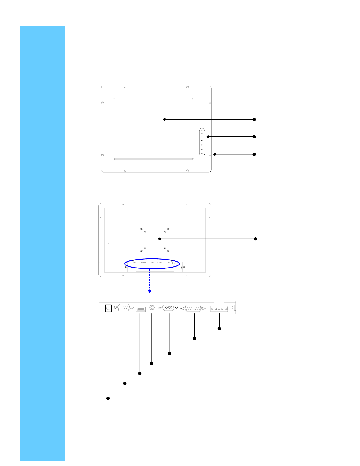
2. 5 Structure Diagram
TFT-LCD
OSD
Rack mount hole
VESA 75/100mm
TouchScreen COM Port
DC-DC Module DC Version Only
DC jack
TouchScreen USB Port
Audio in
VGA in
DVI in
Page 6
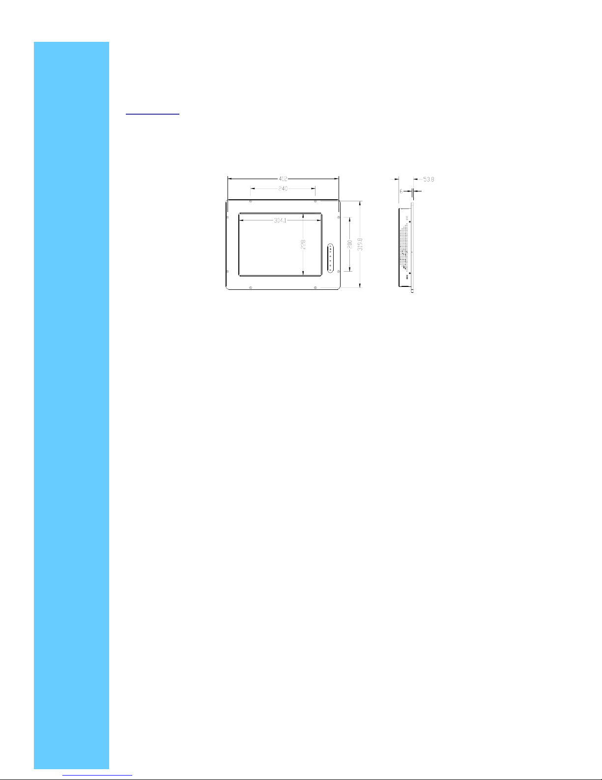
2. 6 Dimension Diagram
IPM-15-FV
Page 7
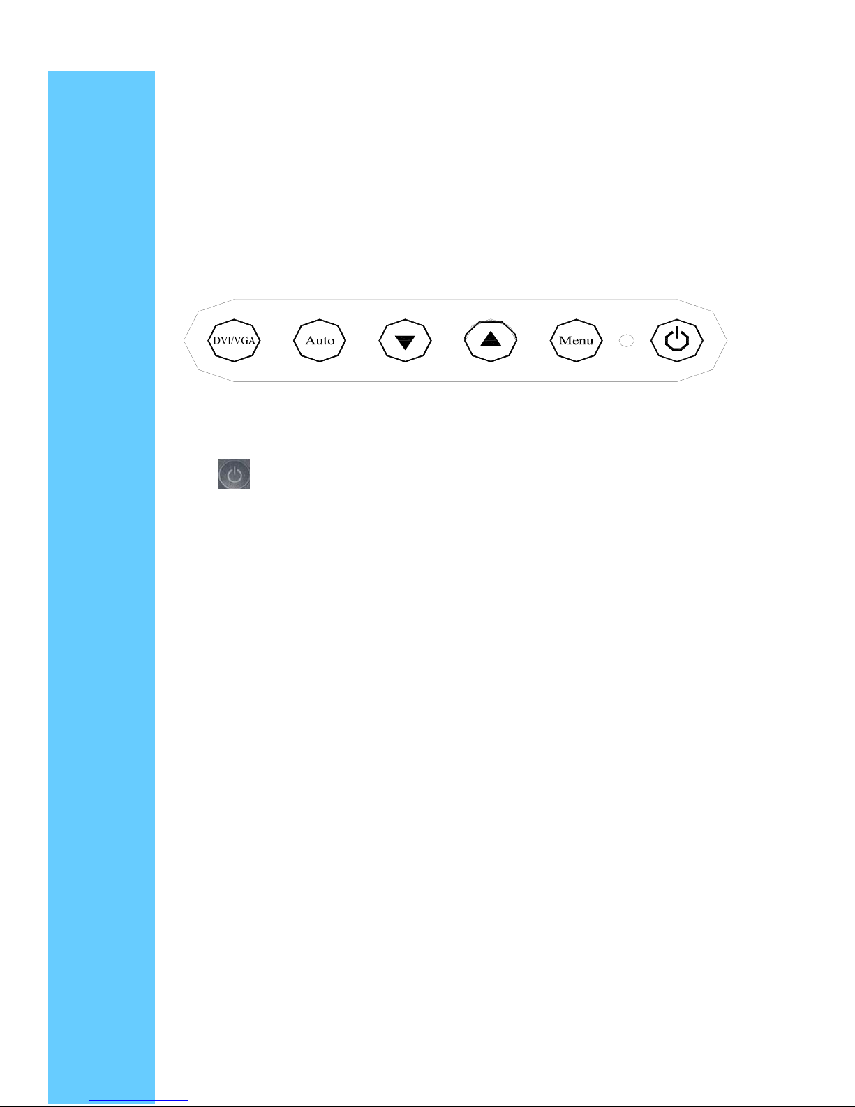
3 Using the System
3. operation
OSD Control Panel
3.1 Power LED Indicator
When the monitor is working, the power LED is green.
3.2 OSD Control key
3.2.2 Menu Key
Press the Menu key to activate the on screen display. It is a toggle key. After 30 sec
idle time, the OSD screen will automatically turn off. Press twice to turn on Confirmation
key, which will bring up the menu and complete the confirmation function
3.2.3 ▲ Key
This button has multiple functions including navigating up or volume up that
can be set to select function in the menu. The adjustment value can be set
directly by pressing “▲”.
3.2.4 ▼ Key
This button has multiple functions including navigating down or volume down that can
be set to select function the menu. The adjustment value can be set directly by pressing
“▼”.
3.2.5 AUTO Key
press the aut0 key to adjust screen color and position.
3.2.6 DVI/VGA Key
press the DVI/VGA key to select desired display input signal. Select video signal
have DVI.VGA.
Switch key 3.2.1
press the power switch key to turn ON or OFF monitor power, NOT a system power
switch.
Page 8
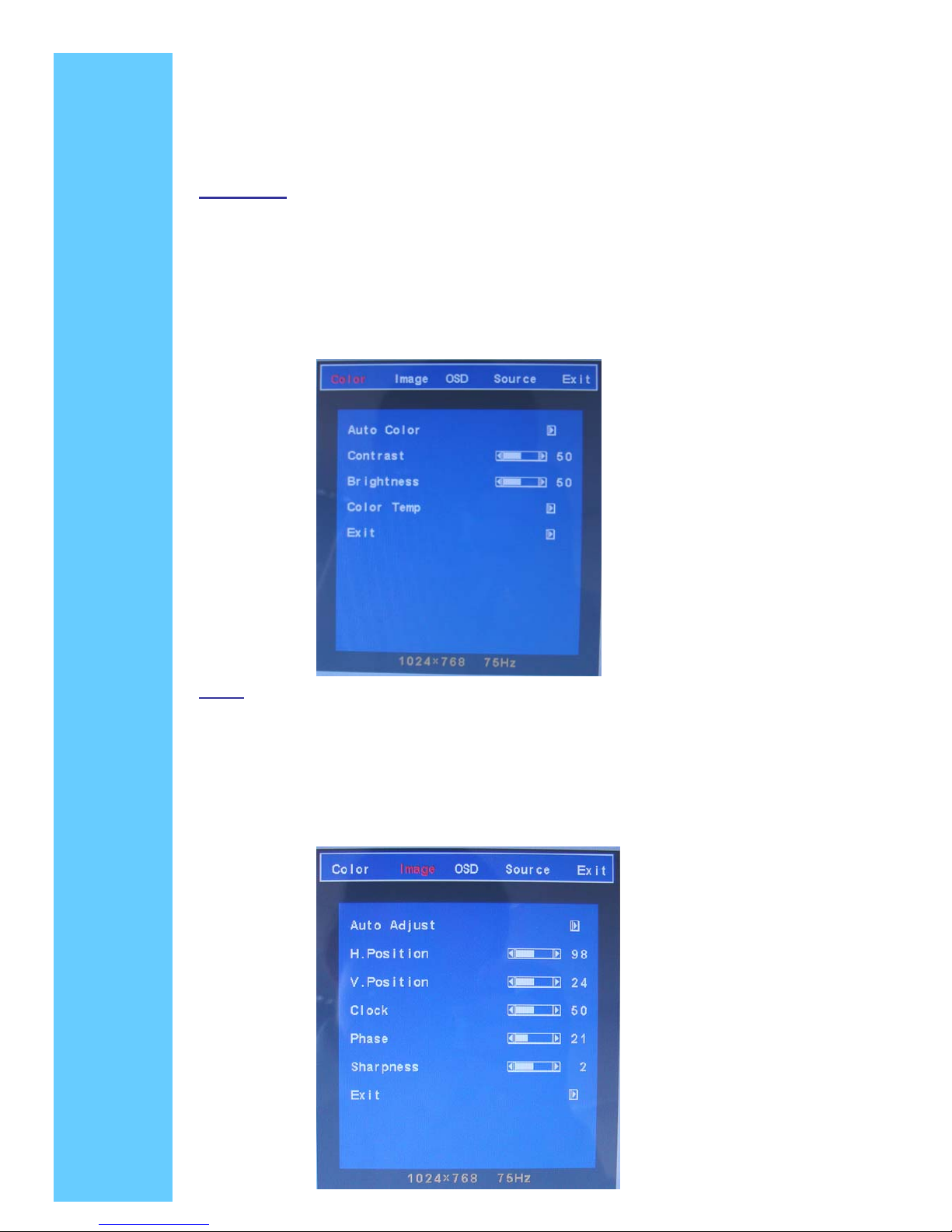
3.3 LCD OSD Menu Operation
Main Menu
Color
Image
OSD
Source
Exit
Color
Auto color: Set favorite color of red, green, and blue
Contrast: It can be adjust image get distinct or vague
Brightness: It can be adjust image get dark or bright
Color Temp: Set color to 9300,6500,5500, User
Exit: Go back MENU
Page 9
Image
Auto Adjust: To perform automatic optimisations of all functions
An “Adjusting “message is displayed during the process
H. Position: It can be moved to left or right side of image
V. Position: It can be adjust image get dark or bright
Clock: Adjust frequency to fill display
Phase: Adjust remove noise and sharpen the image
Sharpness: To mark the image become soft
Exit: Go back MENU
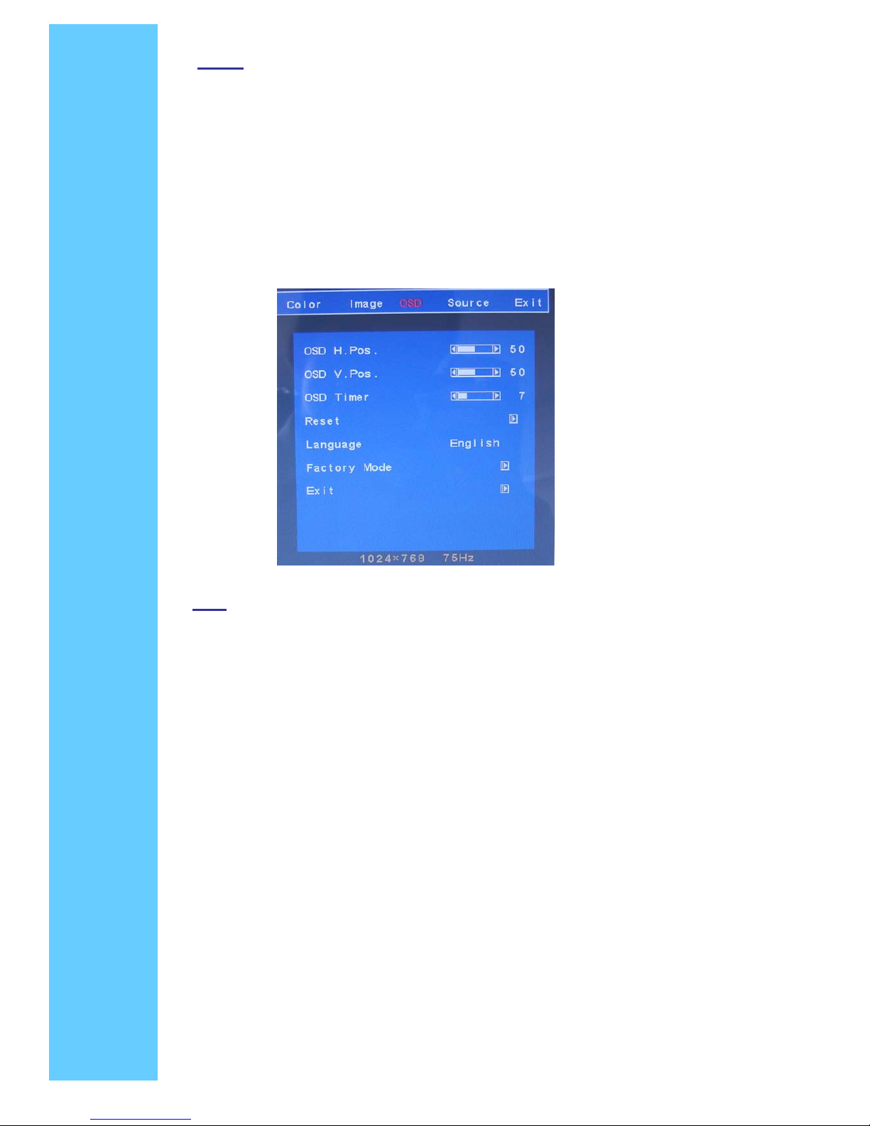
OSD
OSD H. Position: It can be moved to left or right side of OSD
OSD V. Position: It can be moved to up or down side of OSD
OSD Time: It can adjust OSD display time
Reset: Recall Default value
Language: English, simplified Chinese, traditional Chinese, Francais,
Espanol, Japanese, Deutsch,
Factory mode: You can push MENU key & POWER key at same time when
VGA signal input, to entry factory mode. The mode can set
the red, green and blue color of ADC chip. Push the MENU
key for exit.
Exit: Go back MENU
Page 10
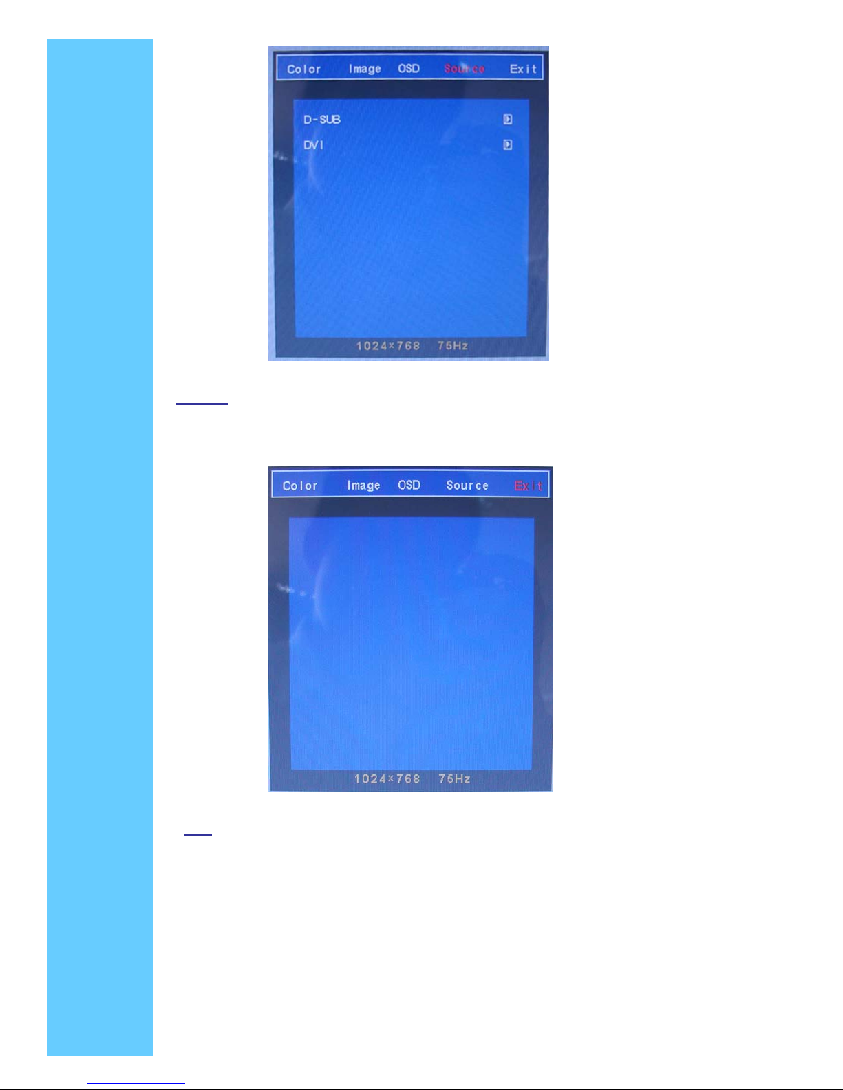
Source
D-SUB: connect VGA PC
DVI: connect DVI PC
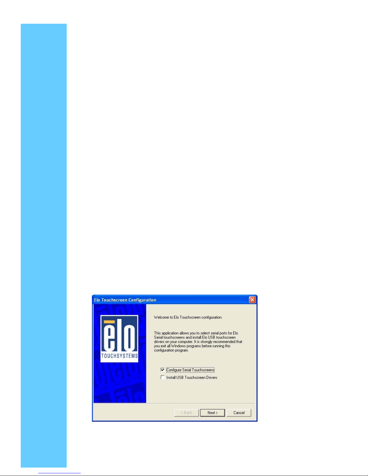
Exit
Exit: Go back MENU
Page 11
4. Installing the Touch screen Driver
4. 1. Hardware
Touchscreen controllers must be configured for the driver prior to installation. Elo typically
ships controllers in a default setup that is compatible with this driver. Controller
requirements are:
Serial
● Serial controllers must conform to these minimum requirements:
● Baud rate-9600 baud.
● Data format-SMARTSET
● It is desirable for a full handshaking connection to be established between the
touchscreen controller and the computer, but it is not required. The controller will function
with this driver in a "two-wire", Receive Data and Ground (RxD and Gnd) configuration.
The consequences of a two-wire connection are:
◇ Automatic detection of the controllers on serial ports during setup is not possible
◇ Controller information will not be registered in the Property Page of the Control Panel
4. 2. Software
There are many options to consider when installing the driver files. This section will explain
the most common ways that the driver is installed. Consult Elo Applications Engineering
for situations not covered in this section.
● Setup from Windows Desktop
● Single monitor, serial controller
◇ Run the self-extracting zip file to unzip the files, using the Run EloSetup option
◇ EloSetup will launch. Check the "Install Serial Touchscreen Drivers" box
● Review and accept the License Agreement
● Check "Auto-detect Elo devices" if your touchmonitor serial cable is connected to
Page 12
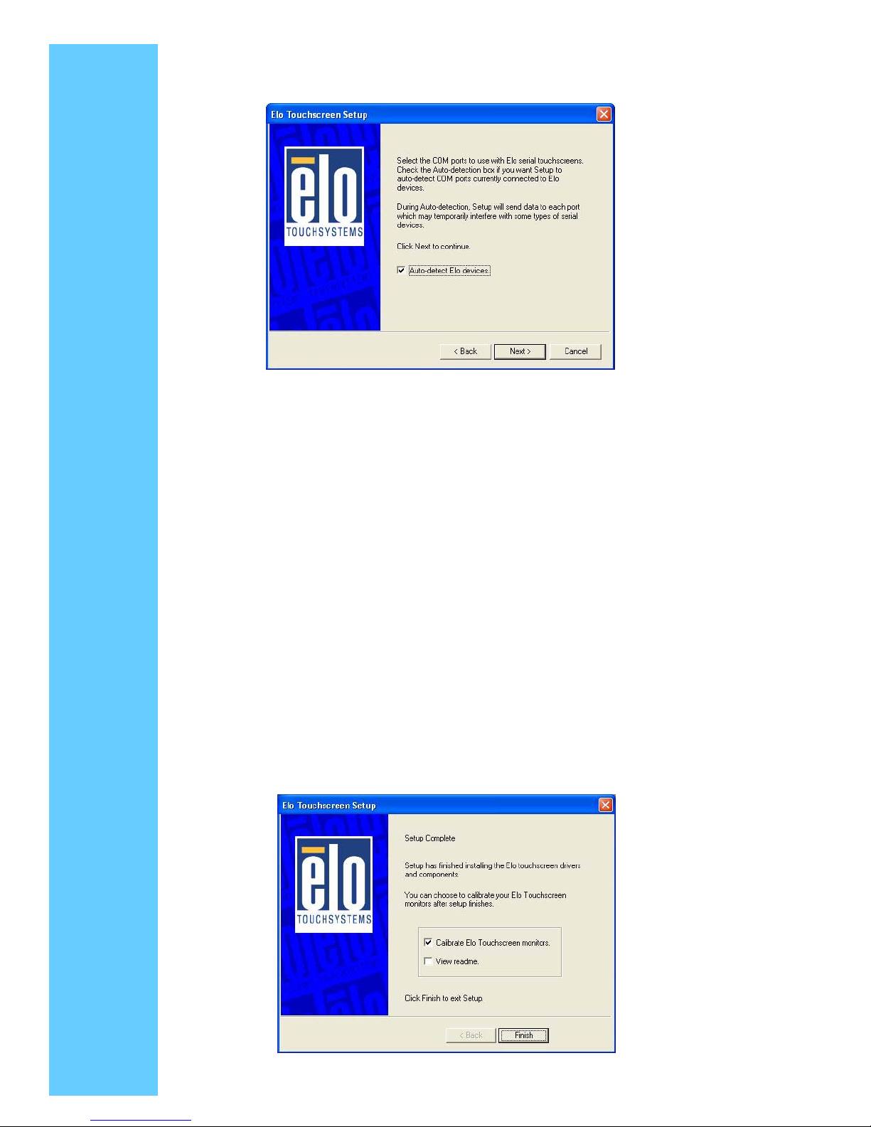
the computer and the serial cable supports hardware handshaking If you connect
the serial cable later, do not check the "auto-detect" box. Go to the next screen
● A list of all the serial ports that the system detected is shown. If you checked the
auto-detect box in the previous screen, and your touchmonitor serial cable is attached
to the computer, the COM port that you selected should be checked in the list. If you
agree with the selection, click Next and proceed to the next
screen
● The COM port you selected will be shown in the window of this screen. This is your last
opportunity to change your COM port selection before the driver files are installed. Use
the Back button(s) to change any of the selections you previously made. Click "Next" to
complete the installation of the driver files
● Depending on the revision of the driver you are installing, Windows may advise you that
the "software you are installing has not passed Windows logo testing…" . Select
"Continue Anyway" to proceed with the installation. This message can be suppressed in
future installations by changing the selection in "Driver Signing Options" at Control
Panel>System>Hardware>Device Manager>Driver Signing
● When the "Setup Complete" screen appears, you may choose to run calibration the (Elo
Video Alignment program, EloVA) immediately or wait until later. If you choose not to
run this program now, you can run it from the Elo Control Panel application
Page 13
● Follow the general procedure for Single monitor, serial controller installation above,
auto detecting or selecting all the serial ports that you will use
● The driver files will install. When the "Setup Complete" screen appears, you may
choose to run calibration (the Elo Video Alignment program, EloVA) immediately or wait
until later. If you choose not to run this program now, you can run it from the Elo Control
Panel application. When EloVA runs for the first time, it will attempt to calibrate all
controllers and/or serial ports that were installed. Press the Esc key on the keyboard to
terminate or skip calibration for any monitor, or allow the program to time out (as
indicated by the progress bar reaching maximum).
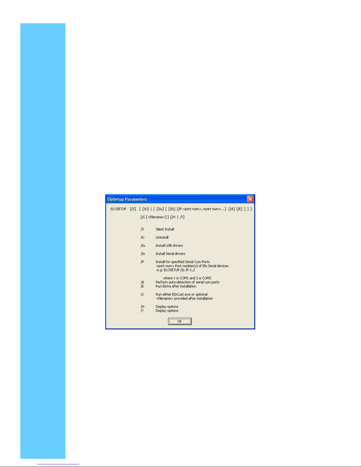
● Silent Install
The EloSetup program for this driver may also be run as an attended or unattended
program from a command line, batch file, etc. Example usage
To Silent install for USB controllers use
EloSetup /iu /s
To Silent install for a Serial controller on COM1 use
EloSetup /is /P:1 /s
To view all the options available for this installation method, run EloSetup as EloSetup /h
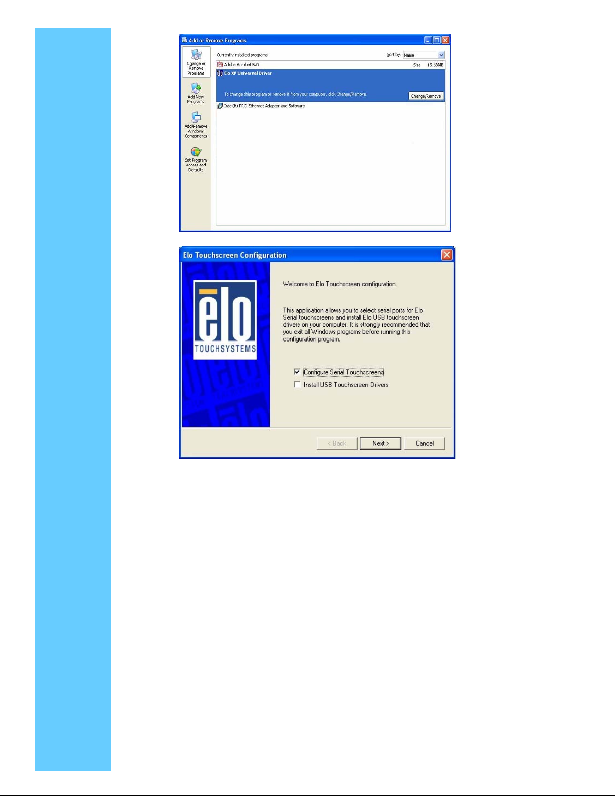
● Adding Additional Serial Controllers
Click on the Change option from the Add/Remove programs in the Control Panel, Elo entry
Page 14
Page 15
4. 3. Control Panel (Elo Mouse Properties)
The Control Panel (CP) application allows configuration of the driver to suit application
programs and presents system and diagnostic information to the user Each of the five or
more tabs in the control panel are described below
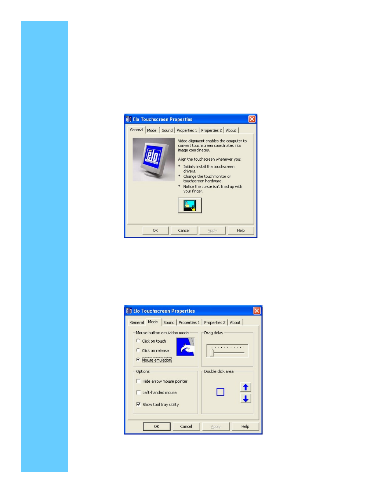
General
The General tab is displayed when the Control Panel is opened. The other tabs described
below may be selected and the video alignment program EloVA may be launched from
this tab.
Mode
The Mode tab selects touchscreen operating mode and configures the appearance and
function ability of the desktop. All selections made in the Mode tab must be activated by
clicking the "Apply" button at the bottom of the dialog
Mouse Button Emulation Mode
This mode is selected by clicking the appropriate radio button
Page 16

● Click on Touch
Click on touch sends immediately upon touch a mouse down/up message at the point of
touch on the touchscreen. The user's finger must be removed from the touchscreen before
a new touch at any location will be recognized. The cursor or selected objects CANNOT be
"dragged" on the screen in this mode
● Click on Release
Click on release sends at the time of release (untouch) a mouse down/up message at the
point that the screen was last touched. Dragging across objects on the screen will not
highlight or select them unless untouch occurs when the touch is over the object.
● Mouse Emulation (Drag and Double-click)
◇ Sends a mouse down message at the point of contact.
◇ Selects an object if it was at the initial point of contact.
◇ Drags a selected object on the screen.
◇ Response to dragging is set by the Drag delay slider bar
◇ Sends a mouse up message at the point of untouch
◇ Double-clicks on an object when the screen is touched twice in rapid succession at the
same location
◇ The speed to achieve double-click is identical to the speed of a successful
double-click with the mouse
◇ Double-click speed is set from the Mouse Properties control panel (Mouse
Properties>Buttons>Double-click speed).
◇ Double click area graphically sets the dimensions of the location around each
clickable icon or object on the screen which will be recognized by Windows as a
double-click. The size of the wire-frame square displayed in the Double click area tab
is the actual size of double-click area accepted by Windows. The square is increased
or decreased in size by touching the appropriate arrows adjacent to the square. Note
that the double-click box size is independent of screen resolution and must be
defined for each user
Options
Options allow various features of the desktop related to the touchscreen to be configured.
Each of the features selected must be activated by clicking the "Apply" button at the
bottom of the tab
◇ Hide arrow mouse pointer turns off the standard mouse cursor
◇ Left-handed mouse interchanges the standard two-button mouse button
assignments
◇ Show tool tray utility activates the Tool Tray utility in the Windows Task Bar. See Tool
Tray for a complete description of this feature.
Page 17
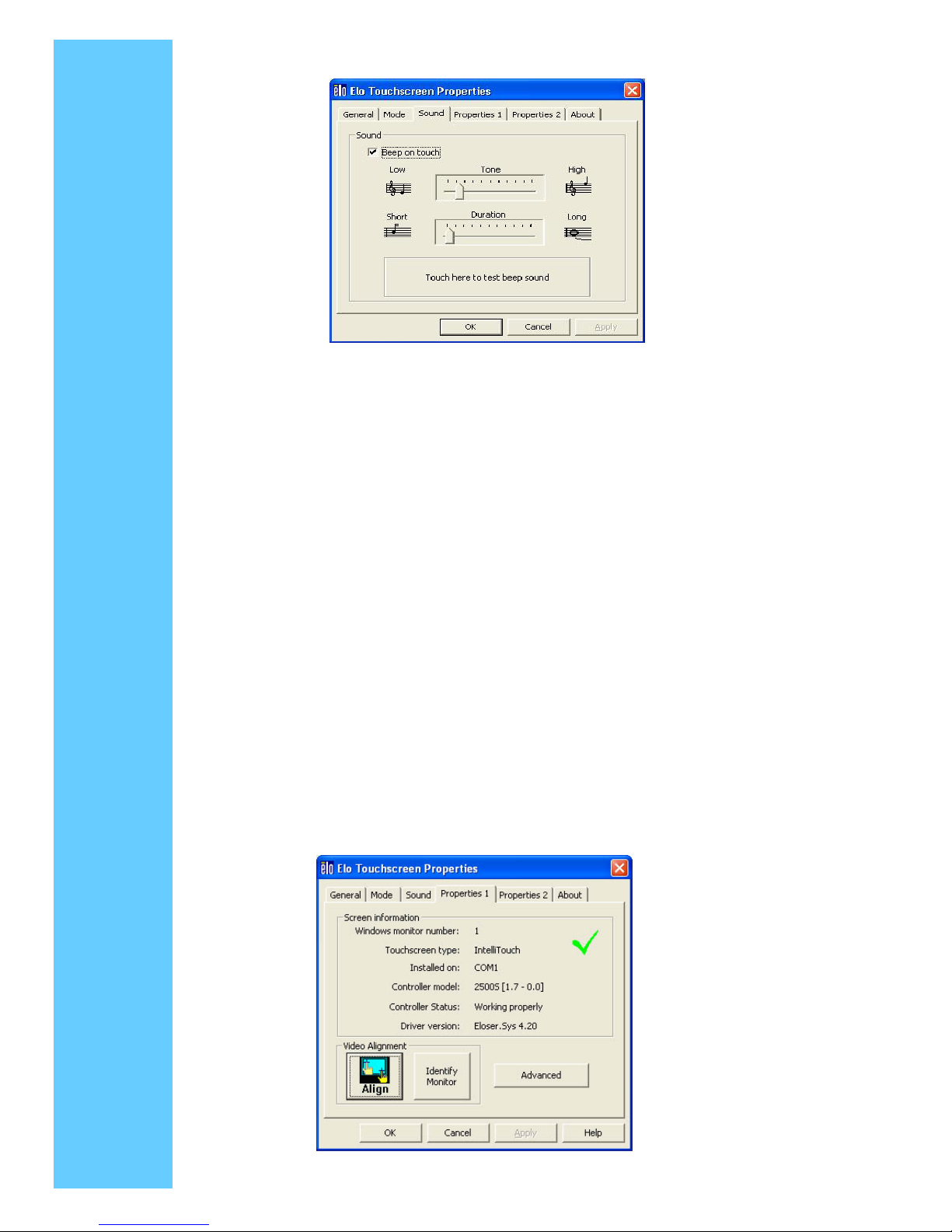
Sound
● The Sound tab sends a single-frequency tone or "Beep" to the system speaker each
time that a valid touch occurs
● The beep is enabled by default when the driver is installed. It may be turned off by
unchecking the Beep on touch box in this tab
● The frequency (Tone) and the Duration of the beep can be adjusted by moving the
appropriate slider in this tab with the touchscreen or mouse, or by using the keyboard
arrow keys
● Selections or changes to the settings in this tab take effect when the "Apply" button is
clicked
Properties
A Properties page will be created for each touchscreen controller installed by EloSetup
and for each serial port reserved for a controller, even if that controller is not present. A
number will be assigned to each Properties page that is related to the order in which
controllers or ports were detected or enumerated. Each Properties page contains
information extracted from the touchscreen controller and the system about the monitor,
touchscreen, controller, and internal driver
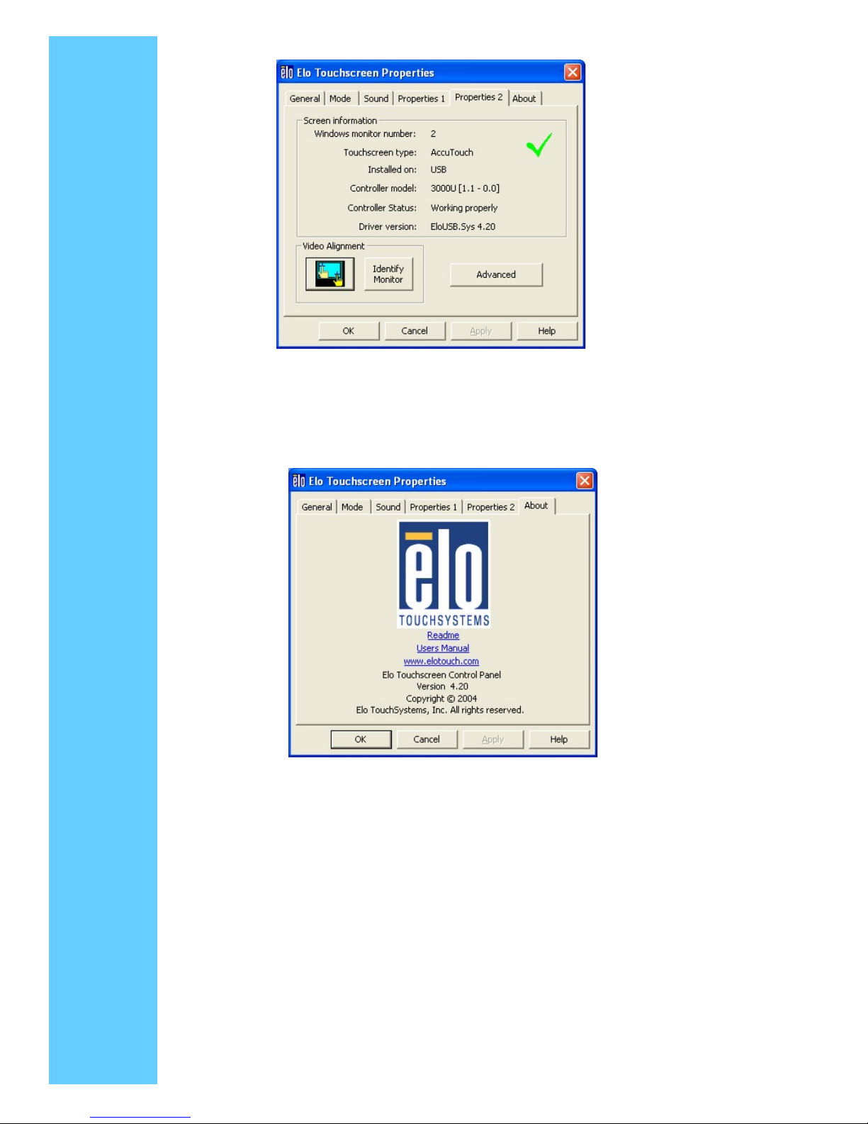
Screen Information
Properties 1
Page 18
Windows Monitor Number
Windows monitor number lists the monitor that corresponds to the "Windows Monitor"
from the Windows Display Properties control panel
Touchscreen Type
Touchscreen Type lists the Elo touchscreen used by its marketing name, i.e., AccuTouch
for Elo's five-wire resistive touchscreen
Installed On
Installed On indicates USB or lists the Windows COM port that a serial touchscreen is
installed on
Controller Model
Controller Model lists the marketing model number of the controller attached. It also lists
the revision of the firmware loaded in the controller
Controller Status
Controller Status indicates either "Working properly" or reflects any errors reported from
the controller
Driver Version
Driver Version lists the version number of the internal driver being used for serial and
USB devices as appropriate
The Video Alignment and Advanced sections appear for touchscreen properties only
when the touchscreen is calibrated
Each Properties page also contains a Video Alignment section that has two functions
The Identify Monitor button will display the Elo logo on the monitor associated with this
Properties page for about one second each time this button is touched
The EloVA icon
will launch the video alignment program only for the monitor
associated with the current Properties page. Running EloVA from the Properties
page avoids the need to align all monitors in a multiple monitor application when only a
single monitor alignment is desired.
If a serial port is reserved for a touchscreen controller that is not actually installed,
the only information contained in the Screen information section of the associated
Properties page will be the number of the Windows COM port. No Screen
configuration icons will be displayed.
Each Properties page also contains an Advanced section
Page 19
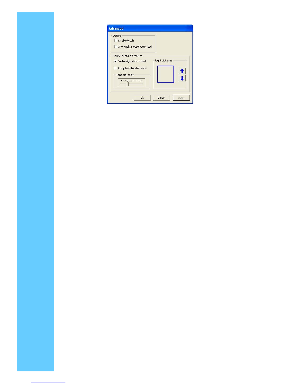
Advanced page contains an Option and Right click on hold section. Option section has:
◇ Show right mouse button tool launches this feature for this monitor. See Right Mouse
Button for a complete description of this feature
◇ Disable Touch stops touch information from reaching Windows for this touchscreen.
This feature may also be activated from the Tool Tray utility. Disabling touch has no
effect on the operation of the standard mouse
Right Click on Hold
Right Click on Hold is a new feature added in version 4.20. This feature allows new and
efficient way of creating right clicks on the touch screen without needing to run the Right
Mouse Button Tool. If the user touches the screen and continues to touch, a right click is
generated on the screen, if the users remains within the Right click area and after the
Right click delay time-out has occured. The right click delay allows the users to perform
other touchscreen operations normally.When the user touches the screen and holds his
finger down, an animated clock is painted at the location, the animated clock continues to
tick and generates a right click at the location after it completes
◇ Enable right click on hold: If checked, it enables this feature for this screen, otherwise, it
is disabled
◇ Apply to all touchscreens: If checked, the current values are set to all touchscreens
when "Apply" or "Ok" button is clicked
◇ Right click delay: Defines the right click delay value in milliseconds. The right click delay
allows the users to perform other touchscreen operations normally.
◇ Right Click Area: Touching within this area generates a right click. This area allows the
user the flexibility to touch within a larger area
NOTE:
◇ Right click on hold feature is enabled only in "Mouse emulation" touch mode.
◇ When Right click on hold feature is turned on, Drag Delay value is set to a minimum
of 25 milliseconds
Properties 2 Tab
Page 20
About
The About tab provides the version of the Control Panel (which is linked to the driver
version) and also provides links to
◇ Readme document included with the driver.
◇ User manual
◇ Elo's web site
Page 21
4. 4. Video Alignment (Calibration)
Video alignment or calibration as it is also called, ensures that the mouse cursor appears
at the position of touch
Elo uses a three-point calibration sequence that will accept touchscreens with any
orientation of the X or Y axis, in landscape or portrait mode
Once calibrated, the touchscreen will be ready to use automatically each time the system
is restarted
Options to Launch
The video alignment program may be launched six different ways:
1. During setup a checkbox may be selected to run the alignment program
automatically after setup is completed.
2. Via the Elo Control Panel application by selecting the General tab and clicking the
alignment program icon
3. Via the Elo Control Panel application by selecting the Properties tab for the
individual monitor and clicking the alignment program icon
4. By clicking the Elo icon in the window task bar at the bottom right of the display and
selecting the video alignment option from the dialog list
5. By double clicking the Elo icon in the Windows task bar at the bottom right of the
display. This will bring up the Elo Control Panel application and the alignment
program may be run via option two or three listed above
6. By running EloVa.exe directly from the Windows command line or
\Windows\System32 directory
7. By calling EloVa.exe directly from an application
Running the Alignment Program
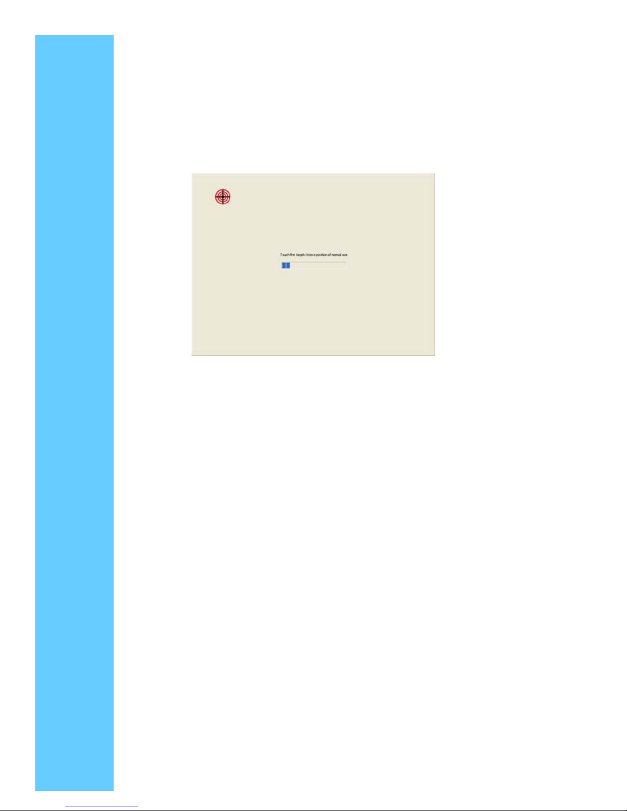
When you run EloVA using one of the options above, touch the three targets as they
appear
You will then be asked to touch various points on the screen to verify that the cursor
appears at the position touched. If the cursor appears at the position touched, click the
green arrow. If the cursor does not appear at the position touched, click the blue curved
Page 22
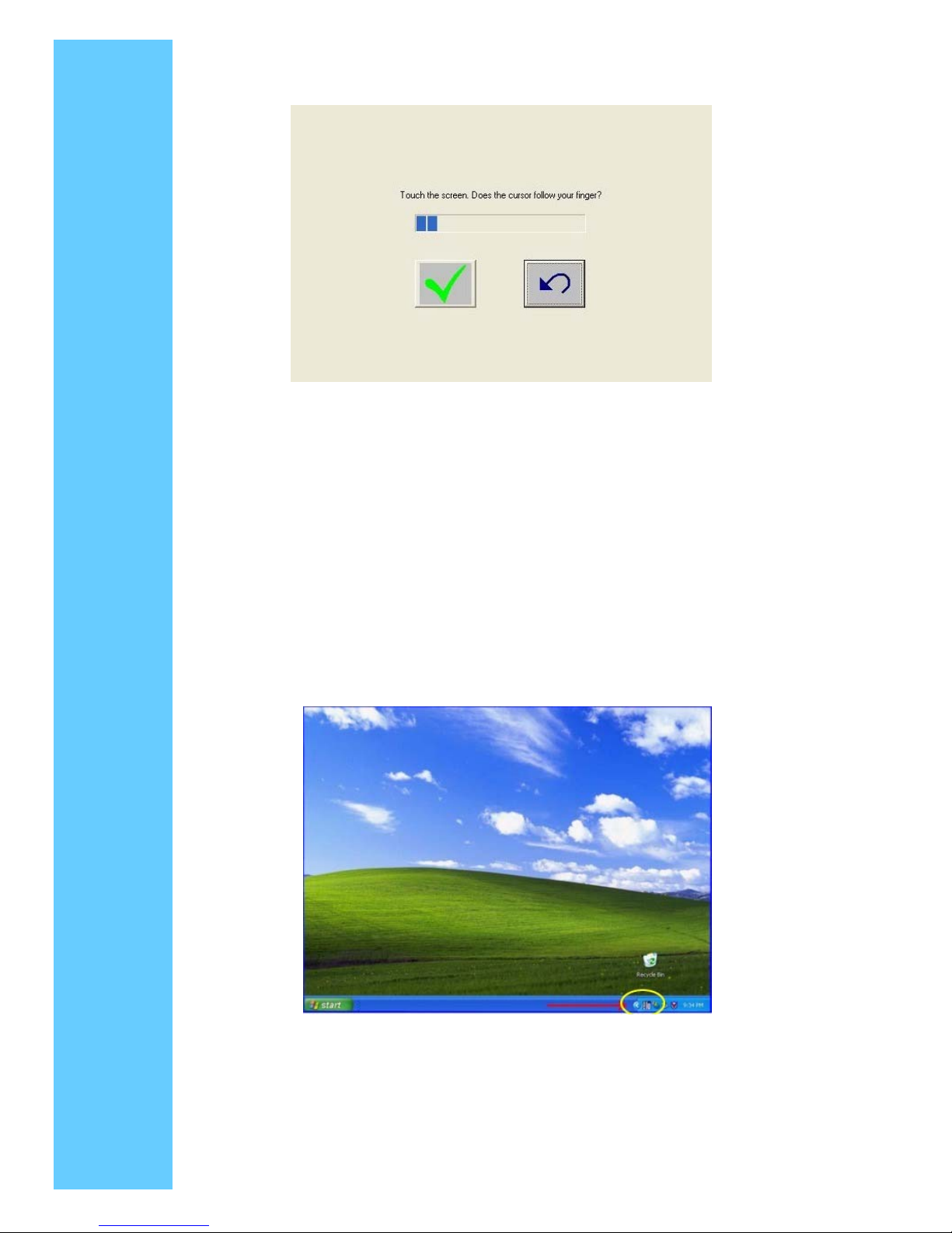
arrow and the alignment program will run again
If you are using multiple monitors the alignment program will run on each individual
monitor. If one of the monitors is not a touchmonitor, Press the Esc key on the keyboard
and the alignment program will advance to the next monitor, or wait until the program
times out as indicated by completion of the progress bar
4. 5. Tool Tray
The Tool Tray application offers a convenient way to access commonly used functions of
the driver from the operating system desktop
To display the Tool Tray icon in the taskbar, it must be enabled from the Control Panel in
the Mode tab. To remove the icon it must be disabled from the Control Panel
The Tool Tray
application is launched with a single left or right click and pops up a menu with several
selectable functions
Page 23
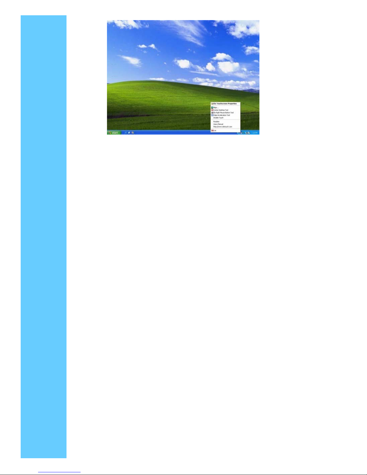
The Tool Tray functions are:
● Elo Touchscreen Properties
A one click method to launch the Elo Control Panel
● Align
Launches EloVA, the Elo Video Alignment program
● Center Desktop Tool
Launches Center Desktop Tool
● Elo Right Mouse Button Tool (RMBT)
Launches Right Mouse Button Tool for all touch monitors that have been calibrated
● Edge Acceleration Tool
Launches Edge Acceleration tool.
● Disable/Enable Touch
◇ When the driver is loaded and running, clicking this segment of the Tool Tray menu
will disable the driver, stopping all touch reports from being sent from the driver to the
mouse handler (MouClass)
◇ When disabled through the Tool Tray, touches made on the touchscreen are not
buffered by the driver, and will not be sent from the driver to MouClass after the
touchscreen is re-enabled
◇ After the touchscreen has been disabled, the state of this segment of the Tool Tray
menu changes from "Disable" to "Enable." Since the touchscreen is now disabled, it
can only be enabled by using the mouse or keyboard. Clicking "Enable" in the Tool
Tray will now restore touchscreen operation
◇ It is also possible to re-enable the touchscreen from the Control Panel after touch
has been disabled from the Tool Tray. Open the Control Panel with mouse or
keyboard, uncheck the "Disable Touch" box in the Mode>Options tab, click "Apply"
and touch is restored
● Readme
Launches Readme instructions.
Page 24
● User Manual
Quick link to this User Manual.
● http://www.elotouch.com
A quick link to Elo's website
● Exit
◇ Clicking this button exits the Tool Tray application and also removes it from the
Windows Taskbar.
◇ The Tool Tray application may also be removed by unchecking it in the Control Panel
and clicking "Apply."
6. Elo Right Mouse Button Tool (RMBT)
Right Mouse Button tool allows a Windows right mouse button simulation on the
touchscreen
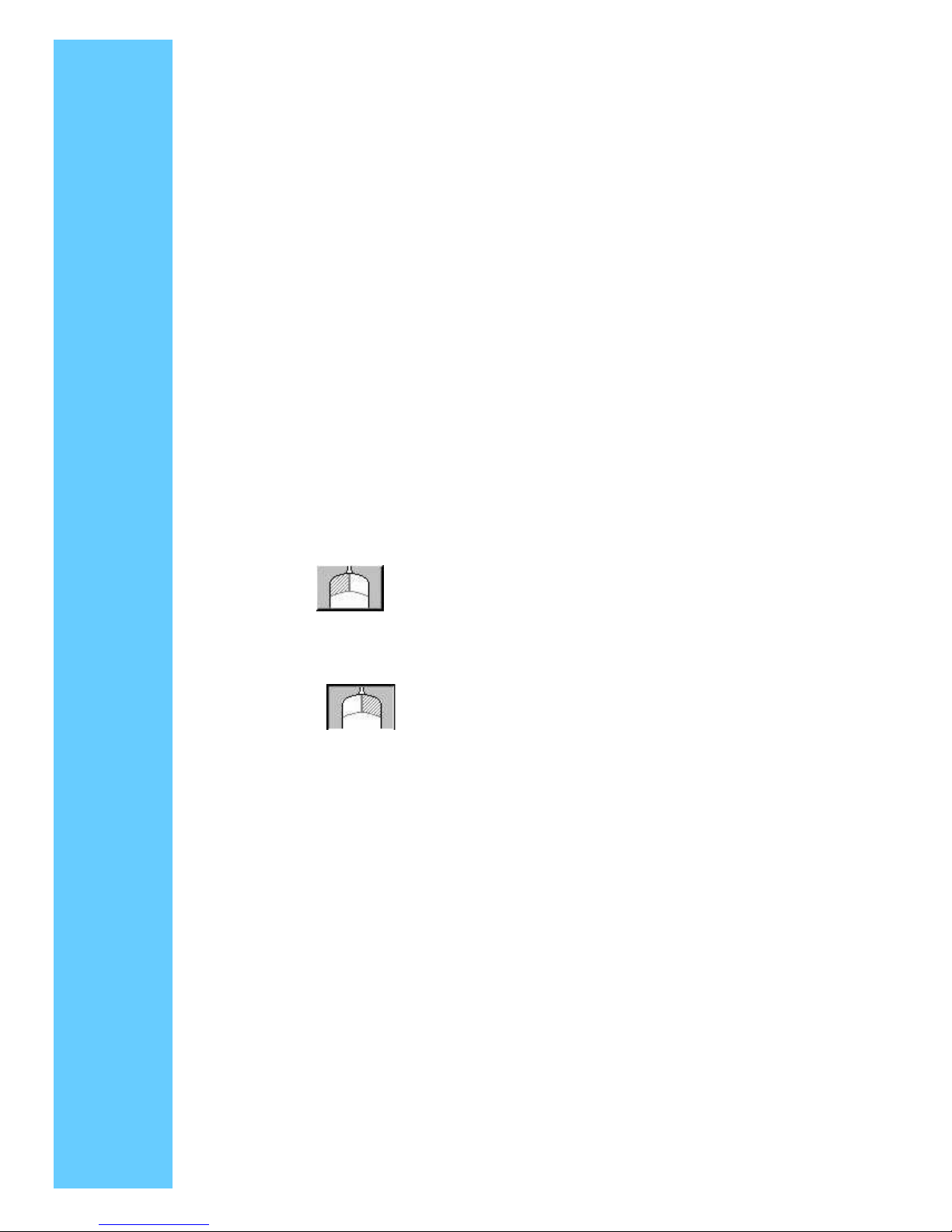
A representation of a typical two-button mouse is displayed in a small window on the
desktop, when this application is run. The initial presentation of the RMBT shows the left
button shaded, indicating that the left button is active. Any touch on the desktop or an
application will produce a left button click consistent with the Button settings in the Control
Panel
A touch in the RMBT will change the shading to show the right mouse button active. Now
any touch on this monitor on which RMBT is running will produce a right button click
Typically, a right button action will activate a new dialog box for some function similar to
mouse right button click. When that dialog box is touched, or any other touch on the touch
monitor is made, this touch will be a left button event. Simultaneously, the mouse button
shading in the RMBT will toggle back to the left button
After the RMBT has been touched to toggle to the right button state, a second touch in the
RMBT will activate a menu allowing the user to:
◇ Launch the Elo Control Panel (Elo Touchscreen Properties)
◇ Close the right button utility
◇ A right button click on the RMBT with the mouse will also activate this menu
The RMBT may be dragged to any location on the desktop by touching it and holding the
touch momentarily until the crossed arrows appear. The RMBT may also be dragged with
the standard mouse
The RMBT cannot be resized
The RMBT can be run for every touchmonitor from the Elo Control Panel > Properties tab
Only one RMBT can be active for each touchmonitor
 Loading...