

Page 1
This User Manual contains the warranty.
A F 8
F L AT O P
F L AT O P
F L AT O P
F L AT O P
F L AT O P
F L AT O P
F L AT O P
F L AT O P
F L AT O P
F L AT O P
F L AT O P
F L AT O P
F L AT O P
F L AT O P
F L AT O PF L AT O P
F L AT O P
F L AT O PF L AT O P
F L AT O P
F L AT O P
F L AT O P
F L AT O P
F L AT O P
F L AT O P
F L AT O P
F L AT O P
F L AT O P
F L AT O P
F L AT O P
F L AT O P
F L AT O PF L AT O P
F L AT O P
LCD PC
U S ER M A N U A L
U S ER M A N U A L
U S ER M A N U A L
U S ER M A N U A L
U S ER M A N U A L
U S ER M A N U A L
U S ER M A N U A L
U S ER M A N U A L
U S ER M A N U A L
U S ER M A N U A L
U S ER M A N U A L
U S ER M A N U A L
U S ER M A N U A L
U S ER M A N U A LU S ER M A N U A L
U S ER M A N U A LU S ER M A N U A LU S ER M A N U A L
U S ER M A N U A LU S ER M A N U A L
U S ER M A N U A L
U S ER M A N U A L
U S ER M A N U A L
U S ER M A N U A L
U S ER M A N U A L
U S ER M A N U A L
U S ER M A N U A L
U S ER M A N U A L
U S ER M A N U A L
U S ER M A N U A L
U S ER M A N U A L
U S ER M A N U A LU S ER M A N U A L
U S ER M A N U A L
Page 2
2
presents dangers, warnings and reasons for
caution when using this device.
presents notes on using the device.
!
A F 8
Please read this manual before you contact
us for serv i c e
Please read this manual before you start to use it.
LCD PC
U S ER M A N U A L
U S ER M A N U A LU S ER M A N U A L
U S ER M A N U A L
U S ER M A N U A L
U S ER M A N U A L
U S ER M A N U A L
U S ER M A N U A L
U S ER M A N U A L
U S ER M A N U A L
U S ER M A N U A L
U S ER M A N U A L
U S ER M A N U A L
U S ER M A N U A L
U S ER M A N U A LU S ER M A N U A L
U S ER M A N U A L
U S ER M A N U A LU S ER M A N U A L
U S ER M A N U A L
U S ER M A N U A L
U S ER M A N U A L
U S ER M A N U A L
U S ER M A N U A L
U S ER M A N U A L
U S ER M A N U A L
U S ER M A N U A L
U S ER M A N U A L
U S ER M A N U A L
U S ER M A N U A L
U S ER M A N U A LU S ER M A N U A LU S ER M A N U A L
U S ER M A N U A L
Page 3
3
T h i suser Manual was produced with careful consideration,
but please let us know if there is anything that is wrong or
needs correcting.
T h i smanual may not, in whole or in part, be reproduced,
photocopied, transcribed, translated, or transmitted in
whatsoever form without the prior permission of the manufacturer.
T h esize and appearance of this device may be changed for
improvement without notice.
Page 4

4
FCC Compliance Statement
This equipment has been tested and found to comply with the limits for a Class B digital device, pursuant to part 15
of the FCC Rules. These limits are designed to provide reasonable protection against harmful interference in a
residential installation. This equipment generates, uses and can radiate radio frequency energy and, if not installed
and used in accordance with the instructions, may cause harmful interference to radio communications. However,
there is no guarantee that interference will not occur in a particular installation.
If this equipment does cause harmful interference to radio or television reception, which can be determined
by turning the equipment off and on, the user is encouraged to try to correct the interference by one or more
of the following measure :
● Reorient or relocate the receiving antenna.
● Increase the separation between the equipment and receiver.
● Connect the equipment into an outlet on a circuit different from that to
which the receiver is connected.
● Consult the dealer or an experienced radio/TV technician for help.
Page 5

5
B a t t e ry Warning Instruction
C a u t i o n
If battery is incorrectly replaced there poses a danger of explosion. Replace Battery only with same or equipment type
recommended by the manufacturer. Discard used batteries according to the manufacturer’s instructions.
Fuse Warning Instruction
C a u t i o n
For continued protection against risk of fire, replace only with same type and rating off use. Disconnect input power
before serving. Only connect this equipment to an earthed socket outlet.
Laser Product
Class 1 Laser Pro d u c t
This appliance contains a laser system and is classified as a 〞CLASS 1 LASER PRODUCT〞. To use this model
properly, read this Owner’s Manual carefully and keep this manual for future reference. In case of any trouble with
this model, please contact your nearest〞Authorized Repair Center〞.
To prevent direct exposure to the laser beam, do not try to open the enclosure.
C a u t i o n
The laser used in the CD-ROM drive can damage your eyes. Do not attempt to open the cover
To reduce the risk of electric shock, do not remove cover(or back).
No user-serviceable parts inside.
Refer servicing to qualified service personnel.
Use of controls or adjustments or performance of procedures other than those specified herein may result in
hazardous radiation exposure.
Do not open the top cover of the drive and never touch the internal parts in order to avoid
EXPOSURE TO INVISIBLE LASER RADIATION.
When the power switch is On, do not place your eyes close to the foat panel opening door and other openings to
look into the inside of the drive.
Page 6

6
I m p o rtant Safety Instru c t i o n s
The following instructions pertain to the risk of fire, electric shock or bodily injury.
Please read all of these instructions carefully.
1. Save these instructions for later use.
2. Follow all of the instructions and warnings marked on this product or included in this manual.
3. Do not use this computer on an unstable cart, stand or table.
The product may fall, causing serious damage to the product.
4. Slots and openings in the cabinet and back have been provided for ventilation.
To ensure the reliable operation of your computer, and to protect in from overheating,
these openings must not be blocked or covered. Don′t use this product on a bed, sofa, rug or
other similar surface. This product should never be placed near or over a radiator or heat register.
This product should not be placed in a built-in installation unless proper ventilation is provided.
5. Never push objects of any kind into the computer through the cabinet openings, as they may
touch dangerous voltage points or short out parts that could result in a fire or electrical shock.
Never spill liquid of any on the product.
6. This computer should only be connected to the AC power source indicated on your computer system′s
information abel. If you are not sure of the type of AC power available,
consult your dealer or local power company. Only connect this computer to a power outlet that matches
the power requirements of this computer.
7 .Do not allow anything to rest on the power cord.
Do not locate this product where people will walk on the cord.
8. If you have to use an extension cord with this computer, make sure that the
total amperage rating of all equipment plugged into it dose not exceed the amperage
rating of the extension cord. Also, make sure that the total of all products plugged into
the main AC power outlet dose not exceed 3.5amps.
9. Unplug your computer from the main electrical power outlet before cleaning.
Do not use liquid cleaners or aerosol cleaners. Use a damp cloth for cleaning.
10. Do not use this computer near water.
11. This product is equipped with a 3-wire grounding type plug, a plug having a third(grounding) pin.
This plug will only fit into a grounding type power outlet. This is a safety feature. If you are unable to
insert or replace your obsolete outlet, contact your electrician to replace your obsolete outlet.
Do not defeat the purpose of the grounding-type plug.
Page 7
7
M a i n t e n a n c e
If the product does not operate normally, adjust only these controls that are covered by
the operating instructions. Improper adjustment of other controls may result in damage
and may require extensive repair work to restore the product to normal operation.
Unplug this product from the main power outlet and call for service under any of the
following conditions :
A. If the power cord or plug is damaged or frayed.
B. If liquid has been spilled into the product.
C. If the product has been exposed to rain or water.
D. If the product has been dropped or the cabinet has been damaged.
E. If the product exhibits a distinct change in performance, indicating a need for service.
S t o p
If you ever have to remove the main system unit cover observe the following
precautions :
A. The power supply cord must be unplugged before the main system unit cover is
removed.
B. Once removed, the cover must be replaced and screwed in position before the power
supply cord is plugged back in.
Page 8
B e fo re You Start
1. Product Features 1 0
2. Equipment Checklist 11
3. Notes on Installation and Operation 1 2
I n t ro d u c t i o n
1. Appearance 1 4
2. Computer Status Indicator Panel 1 6
3. Connecting the Power Cord 1 7
Getting Start e d
1. Booting 1 8
2. Shutdown 2 1
3. Installing the Drivers 2 2
4. Using an External Monitor 4 3
5. Installing a Printer 4 5
6. Using a Wired Keyboard and a Mouse 4 9
7. Using a Wireless Keyboard and a Mouse 5 1
8
Table of Contents
Good usage will give the
p roduct a long life
Thank you for purchasing our F L ATO P
product. In order to receive maximum
e ffectiveness from this product,
please read this manual before you start
to use it.
Table of Contents
Page 9
A dvanced Operat i o n s
1. Entering the System Setup 5 6
2. Turning the power on with the Keyboard 5 7
I m p roved Computer Pe r fo rm a n c e
1. Opening the Computer Cover 6 0
2. Composition of the Mainboard and Connectors 6 1
3. Improving the CPU performance 6 3
4. Expanding the Memory 6 4
5. Installing cards in the Expansion Slot 6 6
Tro u bl e s h o o t i n g 6 8
Table of Contents
9
Page 10
1 0
Before You Start
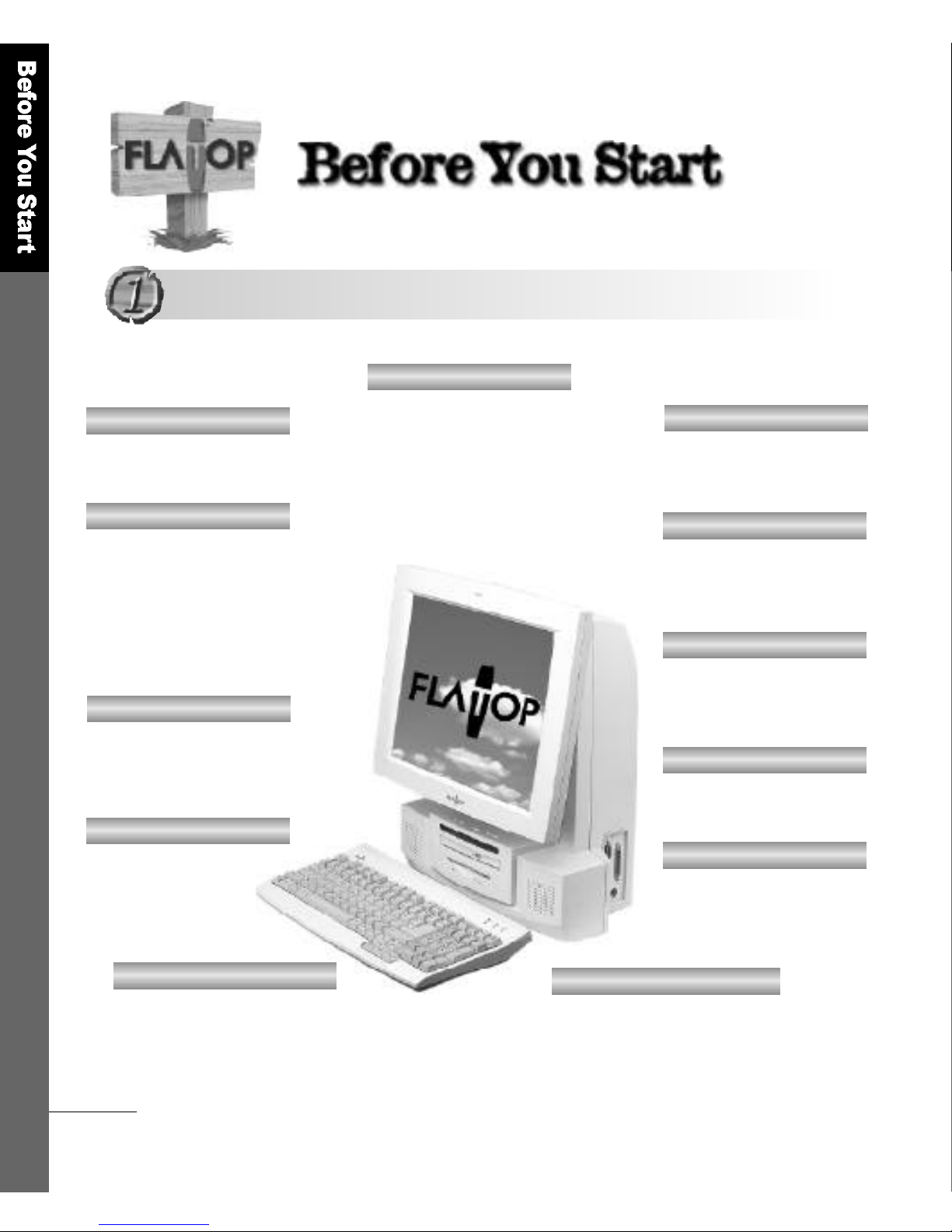
EASY SCALABILITY
Expansion slot with
2PCI/1AMR Bus;2PCI or
1 PCI/AMR Bus
N E T W O R K
Realteck RTL 8139B
V I D E O
Support for Intel 810e
Chipset 3D
CACHE MEMORY
L2 cache memory
of 256KB
CD-ROM DRIVE
24X Slim size
S O U N D
Avance ALC AC′97
sound codec
M E M O RY
64MB DRAM,
expandable to 512MB
K E Y B O A R D/ M O U S E
Choose between
w i r e d / w i r e l e s s
keyboard and mouse
HIGH MOBILITY
light weight of 10.5kg
CPU
Intel PentiumⅢ( F C P G A )
S C R E E N
Vertical viewing angle
of -5°~ 2 5°, Horizontal
viewing angle (+left/-right)
of 120°, and vertical visible
screen angle of 90 °
Product Features
Product Features
MODEL : AF8
LCD
1024 x 768 Max. resolution
and 16.7 million colors on
1 5 .1TFT LCD screen
Page 11
Before You Start
1 1
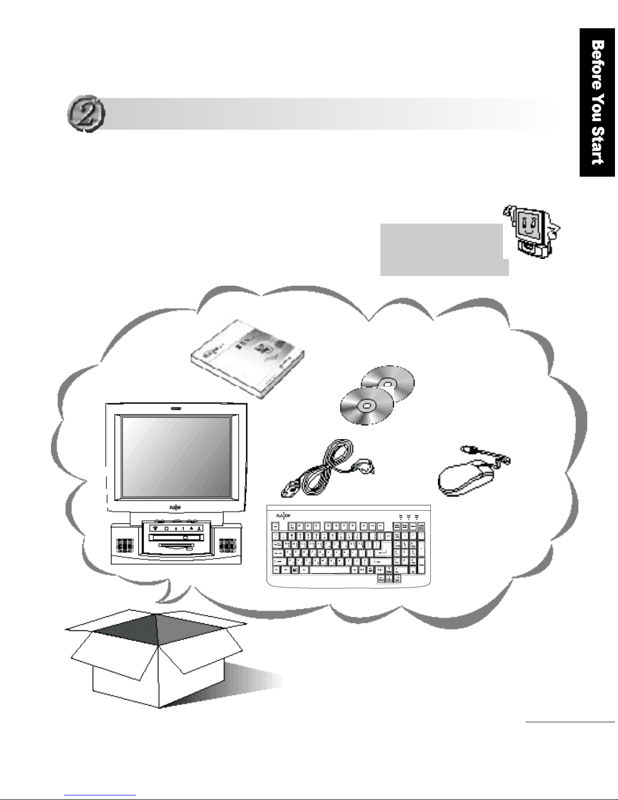
Check to make sure that you have all the following items.
If any of the items are missing or damaged, contact your
dealer immediately.
F L ATO P
Key b o a rd
Mouse
Power Cabl e
User
M a nu a l
F L ATO P
C D s
Wi n d ows 98
CD and
I n s t a l l ation
boot disk
The FLATOP CDs contain the
system programs, device
drivers and utilities.
O p t i on: Wireless Keyboard, Wireless Mouse,
DVD-ROM DRIVE, Mic
Equipment Checklist
Equipment Checklist
Page 12
1 2
Before You Start
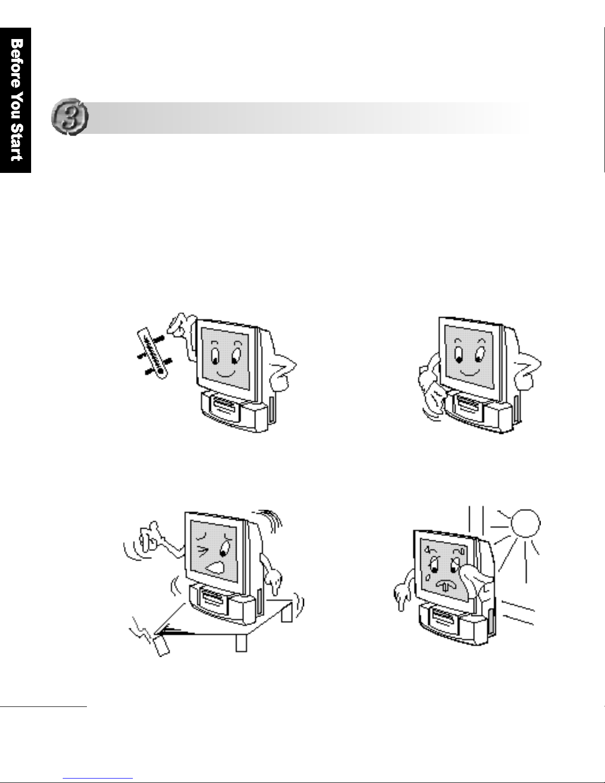
A good installation environment gives the product a longer life.
Please sit the product on a stable and secure surf a c e .
I n s t a l l ation Env i ro n m e n t
Notes on Installation and Operation
Notes on Installation and Operation
Maintain an
optimum
temperature and humidity;
5 - 2 5℃and 30%
Clean the LCD
panel with a soft
materials(such as
cotton cloth)
Sit the product on
a stable and
secure surface
Install the
product in a
w e l l - v e n t i l a t e d
room, not
exposed to
direct sunlight.
Page 13
Before You Start
1 3
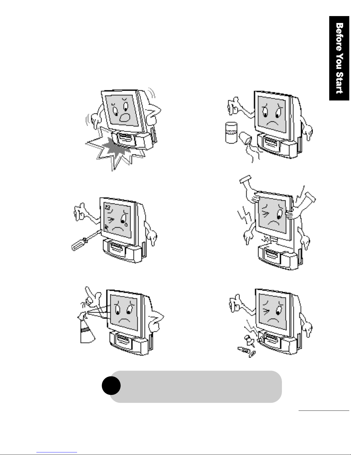
Damage caused by the user′s misuse or carelessness is
not covered by the warranty service.
!
Cautions in Use
Do not drop or
shake the product.
Do not spill
beverages,
such as coffee,
on the product
Do not scratch or
jolt the LCD
s u r f a c e .
Do not lift up the
product by holding
the LCD panel.
Do not spray any
detergent
directly onto the
LCD screen.
(lest you mark
the screen
p e r m a n e n t l y )
Do not insert any
f o r e i g n
substances into
p r o d u c t .
Page 14
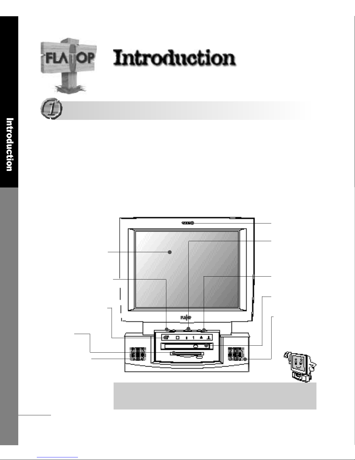
Become familiar with the names of the extern a l
C o m p o n e n t s
■ The Fro n t
This section describes the appearance and the various buttons and
functions of the product. Please refer to the brief descriptions and
names given in the illustrations in order to learn the functions of each
c o m p o n e n t .
M i c r o p h o n e
Power Button
Speaker V o l u m e
CD-ROM DRIVE
Built-in Speaker
1 5 . 1TFT LCD Panel
LCD Screen Brightness
Status Indicator Panel
3 . 5F D D
Built-in Speaker
This 392(W)mm x 430(H) sized product provides a space-saving feature and
the display gives vertical viewing angles between -5°and 25 °and a clean
screen quality even when you view it from the side.
▶ Built-in Microphone (option)
▶ Power can be turned On or Off
when the power cord is connected
to a wall outlet (standby mode)
▶ adjusts the speaker volume
▶ 24X Slim size CD-ROM drive
▶ Max. 5W output
▶ 16.7 million colors at 1024 x 768 Max.
r e s o l u t i o n
▶ Adjusts the LCD Screen Brightness
▶ Indicates the current status of
o p e r a t i o n
▶ Max. 5W output
▶ 1.44 Floppy Disk Drive
1 4
I n t r o d u c t i o n
Appearance
Appearance
Page 15
I n t r o d u c t i o n
1 5
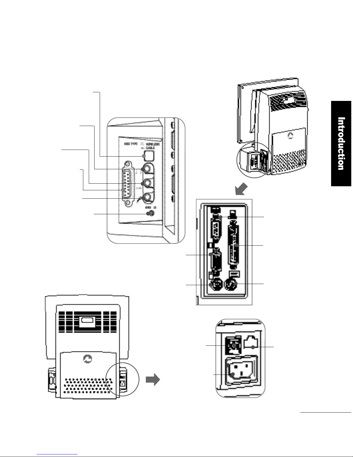
Serial Port
■ The Back
Parallel Port
Mouse Connector
Video Connector
Selector Switch
for Keyboard
Line in
M i c r o p h o n e
J o y s t i c k / M i d i
Wireless Keyboard
ID Reset Switch
Keyboard Connector
▶ Select between wired and
wireless keyboard
▶ Output terminal for
external speakers
▶ Game port and Midi
▶ Terminal for External
M i c r o p h o n e
▶ The reset switch for the
wireless keyboard ID
▶ External monitor
connection point
▶ PS/2 type mouse connector
▶ Communication port (COM1)
▶ Printer port (LPT1)
▶ PS/2 type keyboard connector
Speaker Out
USB Port
Power Connector
RJ-45 Port
▶ Input for 240V/100V
p o w e r
▶ 1 0 / 1 0 0 M b p s
Ethernet port
▶ Port for USB
c o n n e c t i o n
Page 16
1 6
I n t r o d u c t i o n
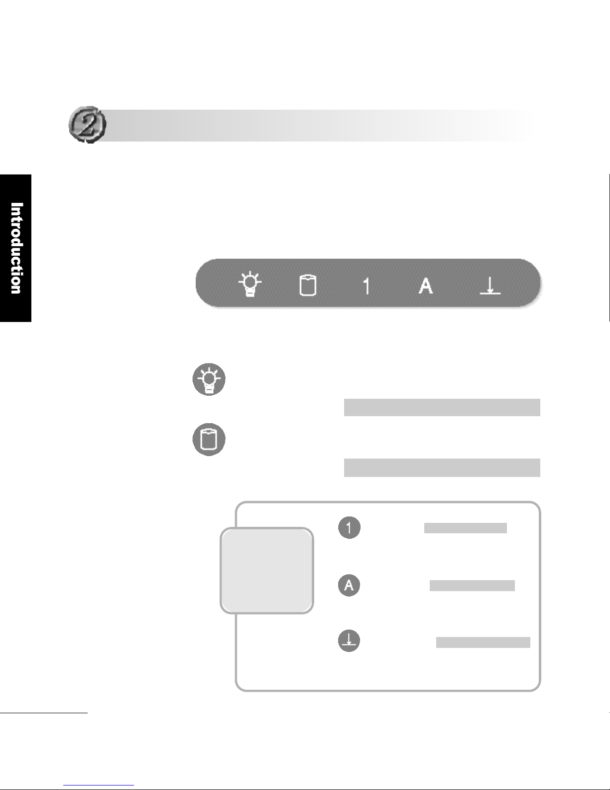
:When this light is on, it means the computer′s
power is on.
: When this light is on, it means the computer
is accessing the internal hard disk.
Power-On Indicator
L i g h t
HDD In Use Indicator
L i g h t
These indicator
lights are on
when a wireless
keyboard is being
u s e d !
The computer status indicator panel shows the current operation
of the computer. There is a symbol for each indicator light on
F L AT O P′s indicator panel for the user to easily understand
the current status of the computer.
R e d : Normal power-on
Green : HDD in use
Green: NUM LOCK in use
Green: CAPS LOCK in use
Green: SCROLL LOCK in use
Computer Status Indicator Panel
Computer Status Indicator Panel
NUM LOCK
CAPS LOCK
SCROLL LOCK
This indicates that the number keypad
of the FLATOP wireless keyboard
This indicates that the alphabet can be
used only in capitals
The arrow keys can be used as the
keys for screen adjustment
POWER-ON HDD In Use NUM LOCK CAPS LOCK SCROLL LOCK
Page 17

I n t r o d u c t i o n
1 7
Connect one end of the power cord to the power connector on
the back of the computer as shown below.
Connect the other end to the 240V/100V wall outlet.
When the computer is connected to the wall outlet, but is not
being used, it will automatically switch to standby mode.
The FLATOP voltage is automatically set between 100V and
240V without using a conversion switch.
1
2
3
When the computer is in the standby mode pressing either the
power button or any key can start the computer.
Connecting the Power Cord
Connecting the Power Cord
Power connector
Power cord
Wall outlet
Page 18
1 8
Getting Started
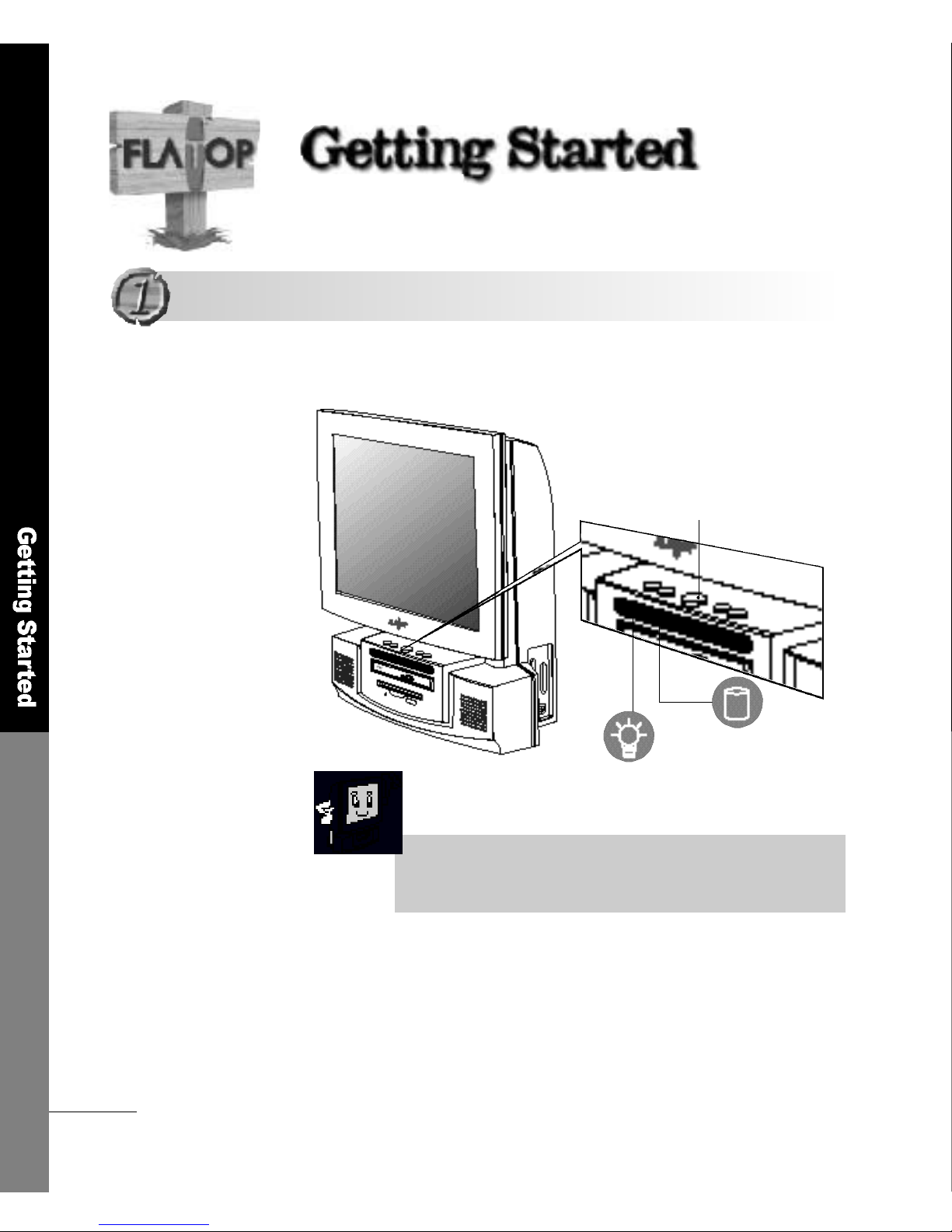
Power button
If you press the power button softly, as shown below, the power
indicator light turns on.
Please make sure that the keyboard, mouse and other peripheral
devices are correctly connected before you turn the computer on.
B o o t i n g
B o o t i n g
■For turning the power on using the key b o a rd
If using Keyboard/Mouse Power On in the [Integrated Peripherals]
section in CMOS Setup utillty, you can turn the computer on by
entering the password.
HDD indicator light
Power-On indicator light
(please refer to page 47)
Page 19
Getting Started
1 9
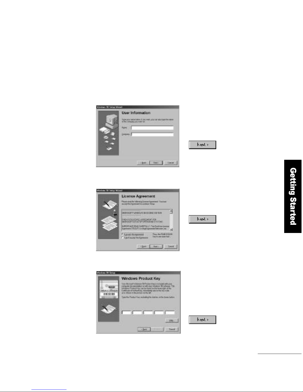
The first thing you have to do when you turn
the computer on for the first time
A window appears prompting you
to enter information about
yourself. Enter your name and
your company, and click the
b u t t o n .
A window showing the license
agreement appears. Select
A g r e e and click the
b u t t o n .
1
2
The authentication window appears.
Enter the product number provided
in the Windows 98 User M a n u a l
(enclosed with the computer).
Enter the number and click the
b u t t o n .
3
Page 20
2 0
Getting Started
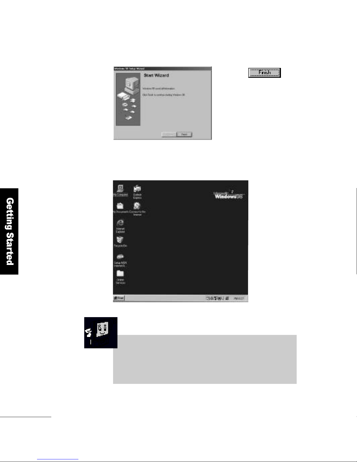
Click the button in
the start wizard window.
Windows 98 starts.
4
5
FLATOP has a variety of software, including Microsoft Windows 98,
installed in its hard disk. Please read the Windows 98 User′s
Manual carefully to gain insight into its operation.
Page 21
Getting Started
2 1
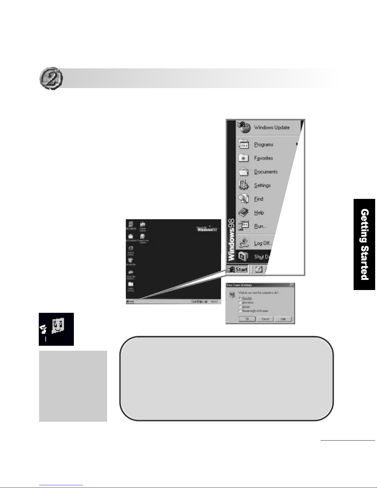
Computer Shutdown
Click S t a rtand select
Shut downto turn the
computer of f .
The computer turns off
automatically after 3~4 seconds
When you are not use
the computer for a long
period of time, moving
it or cleaning it, please
be sure to disconnect
the computer from the
wall outlet.
S h u t d o w n
S h u t d o w n
Please follow this method if the computer does not operate
n o r m a l l y,or if it needs a restart due to an error occurring.
1. Click <Ctrl> + <Alt> + <Del> keys.
2. Press and hold the power button for 4 seconds or more,
and release it.
( When the computer does not restart as in No.1 above )
Page 22
2 2
Getting Started
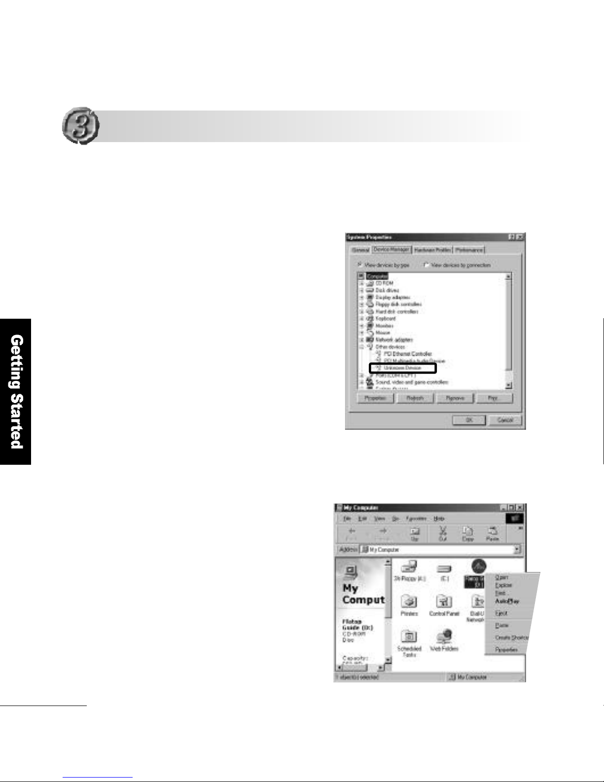
Double-click the My Computer icon on the desktop. Right-Button click
the CD-ROM disk and select O p e n.
Double-click the I N F _ U P D AT E f o l d e r. Run the Setup.
1
➊
➊
How to install INF_UPDAT E
If Unknown deviceis indicated in the Device Manager of the System
other device Properties dialog box, follow this procedure.
Installing the Drivers
Installing the Drivers
Page 23
Getting Started
2 3
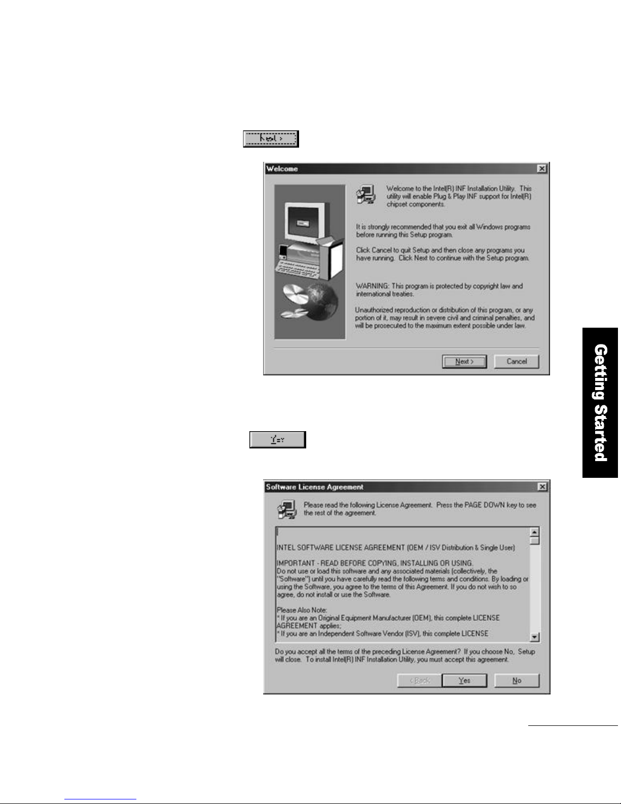
Click the button to continue the setup.
2
Select the button in the S o f t w a r e License Agreement.
When the setup is complete, restart the system.
3
Page 24
2 4
Getting Started
How to Install the Video Driver
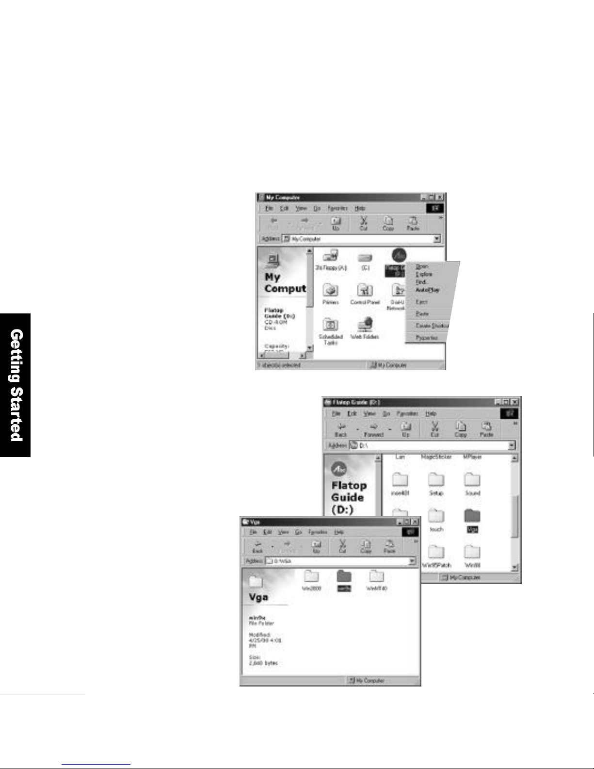
Double-click the My Computericon. Right-Button click the CD-ROM
disk and select O p e n
➋
➋
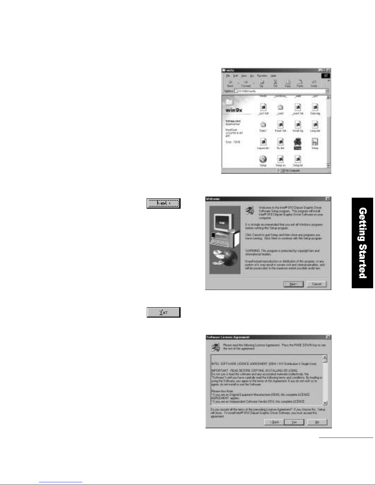
Open the V G Afolder and
then the W i n 9 xf o l d e r.
1
Page 25
Getting Started
2 5
Run the S e t u p.
2
Click the b u t t o n .
3
Click the button in the
Software License Agreementw i n d o w.
4
Page 26
2 6
Getting Started
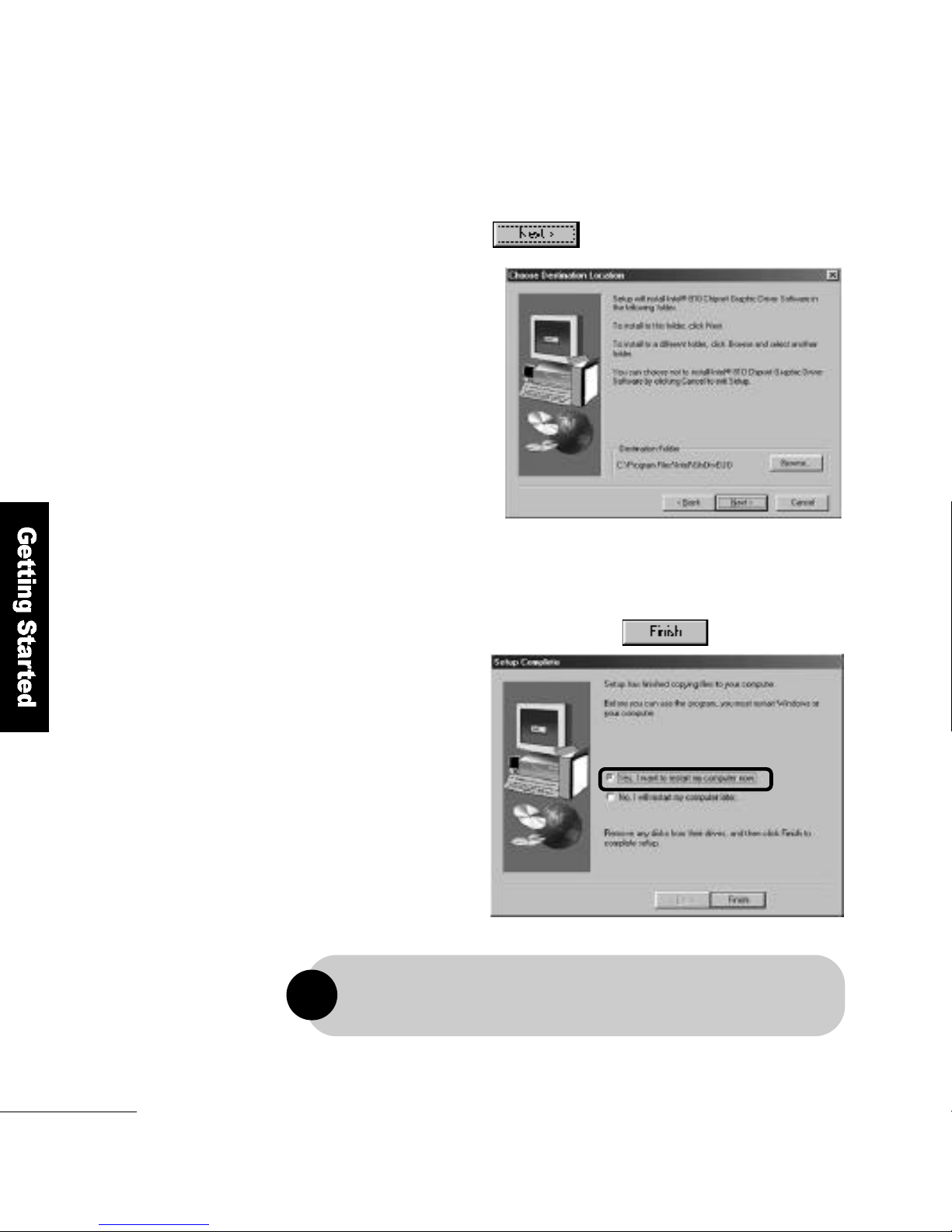
Select the folder into which the V G A driver will
be installed and click the b u t t o n .
5
When the driver installation is complete, select
Restart the ComputerN ow and click the b u t t o n .
6
For a trouble-free driver installation, please be sure to restart the computer.
!
Page 27
Getting Started
2 7
1
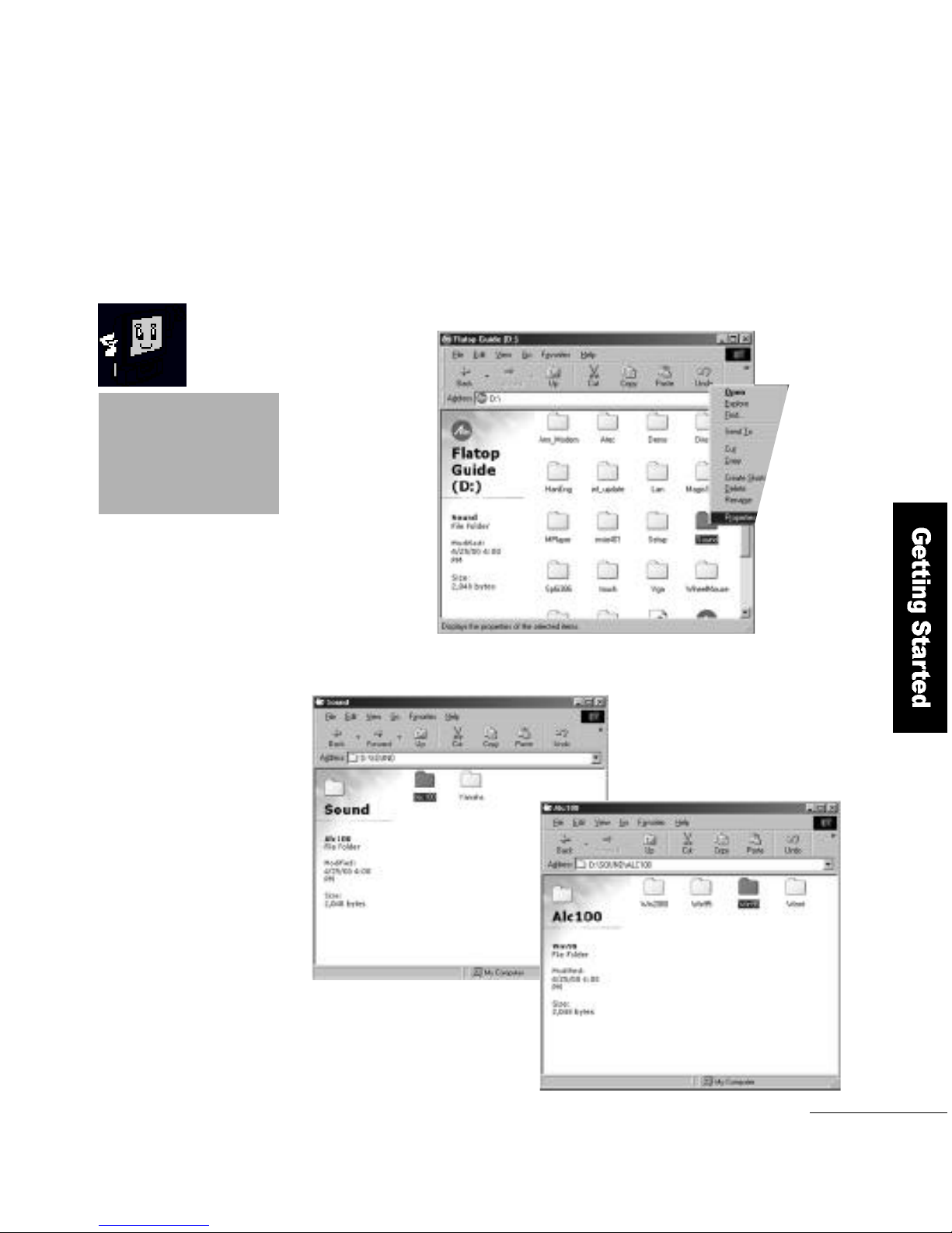
Open AL C 1 0 0 and then
Windows 98
2
How to Install the Sound Driver
( AVA N C E - A L C 1 0 0 )
➌
➌
If a PCI Multimedia Audio
Device exists, it means
the sound driver is not
i n s t a l l e d .
Right-Button click onSound folderon the CD ROM and select Op en
Page 28
2 8
Getting Started
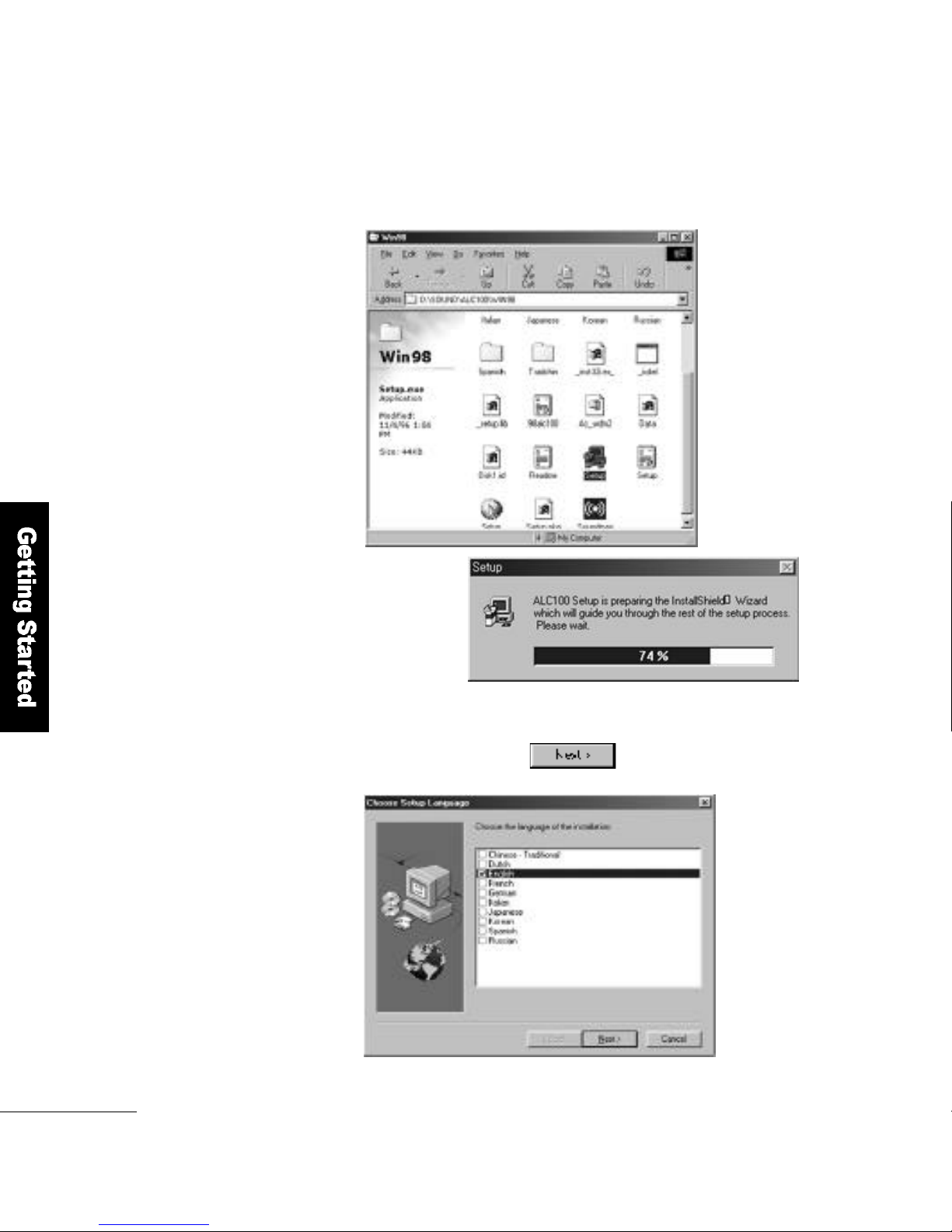
Run the S e t u p.
3
Choose E n g l i shand click the b u t t o n .
4
Setup Process
Page 29
Getting Started
2 9
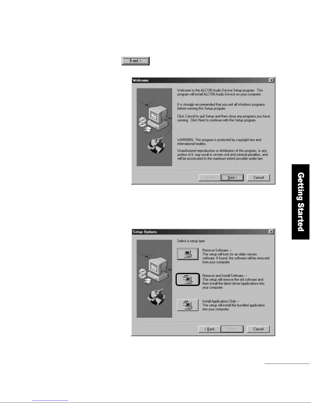
Click the b u t t o n .
5
Click the Add/Remove softwareicon for the setup options
6
Page 30
3 0
Getting Started
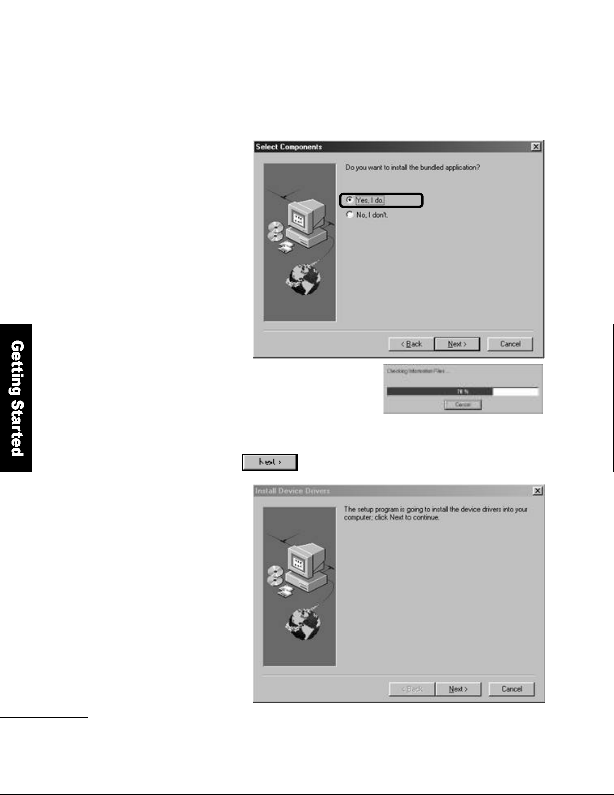
Select Yesfor application installation.
7
8
Click the b u t t o n .
Page 31
Getting Started
3 1
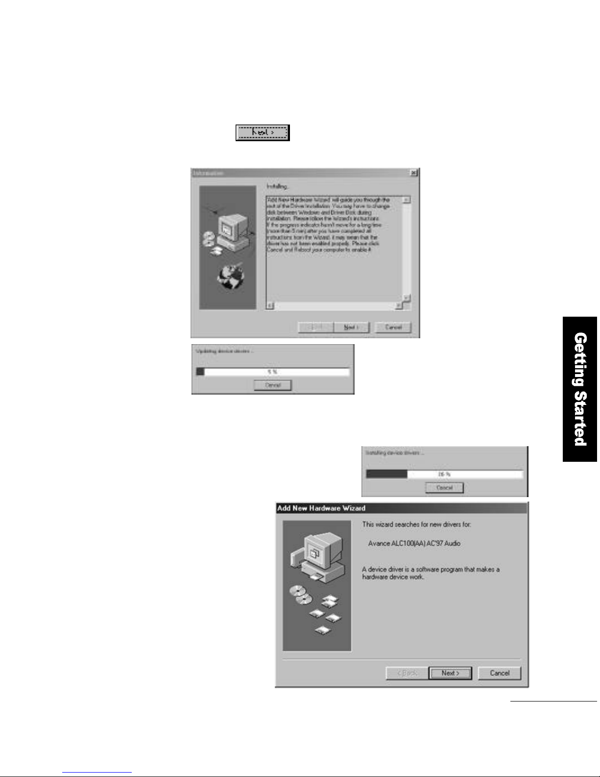
9
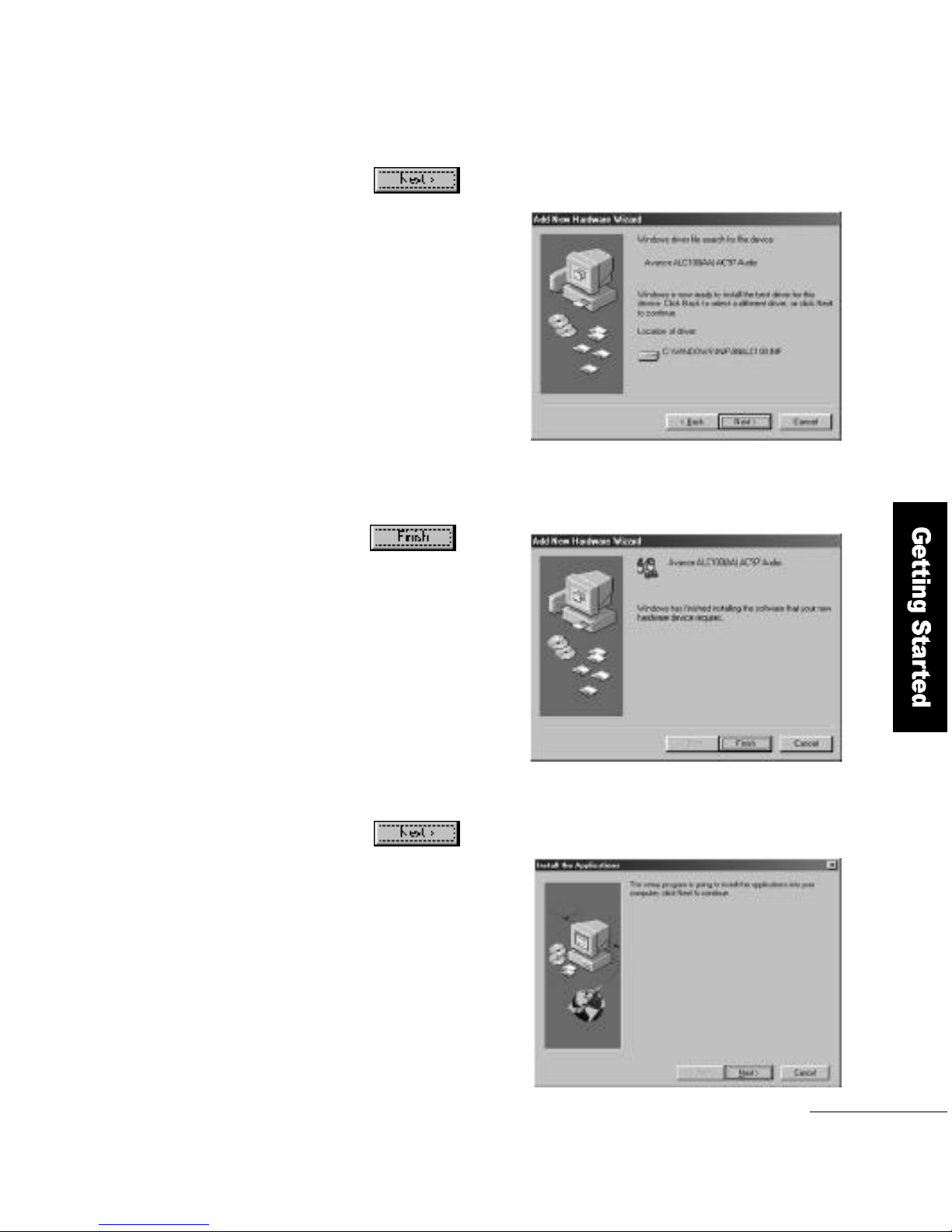
If the Add New Hardware Wi z a r d wants to search for a driver,
click the b u t t o n .
Page 32
3 2
Getting Started
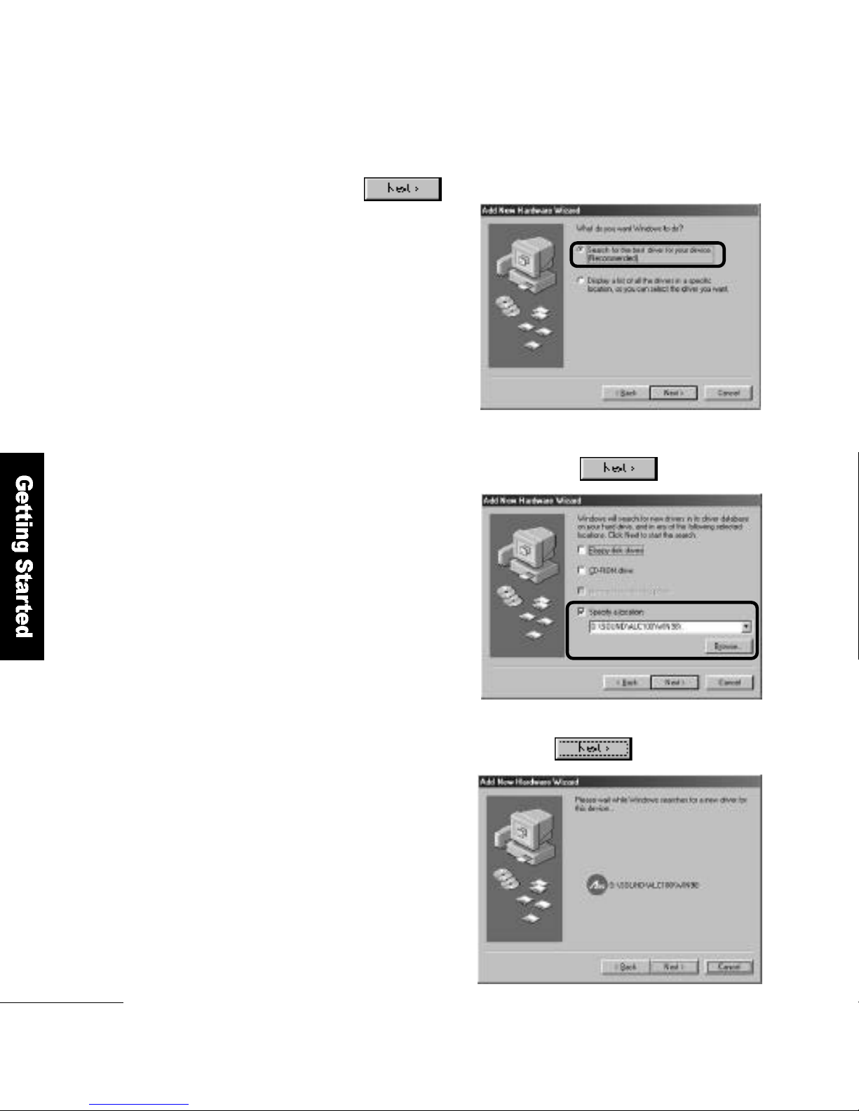
Select Search for the best driver for your device (Recommended)
and click the b u t t o n .
1 0
Specify the location to search in and click the b u t t o n .
1 1
If any new driver are discovered, click the b u t t o n .
1 2
Page 33
Getting Started
3 3
Click the button to copy the driver file.
1 3
When driver installation is complete,
click the b u t t o n .
1 4
Click the button for application installation.
1 5
Page 34
3 4
Getting Started
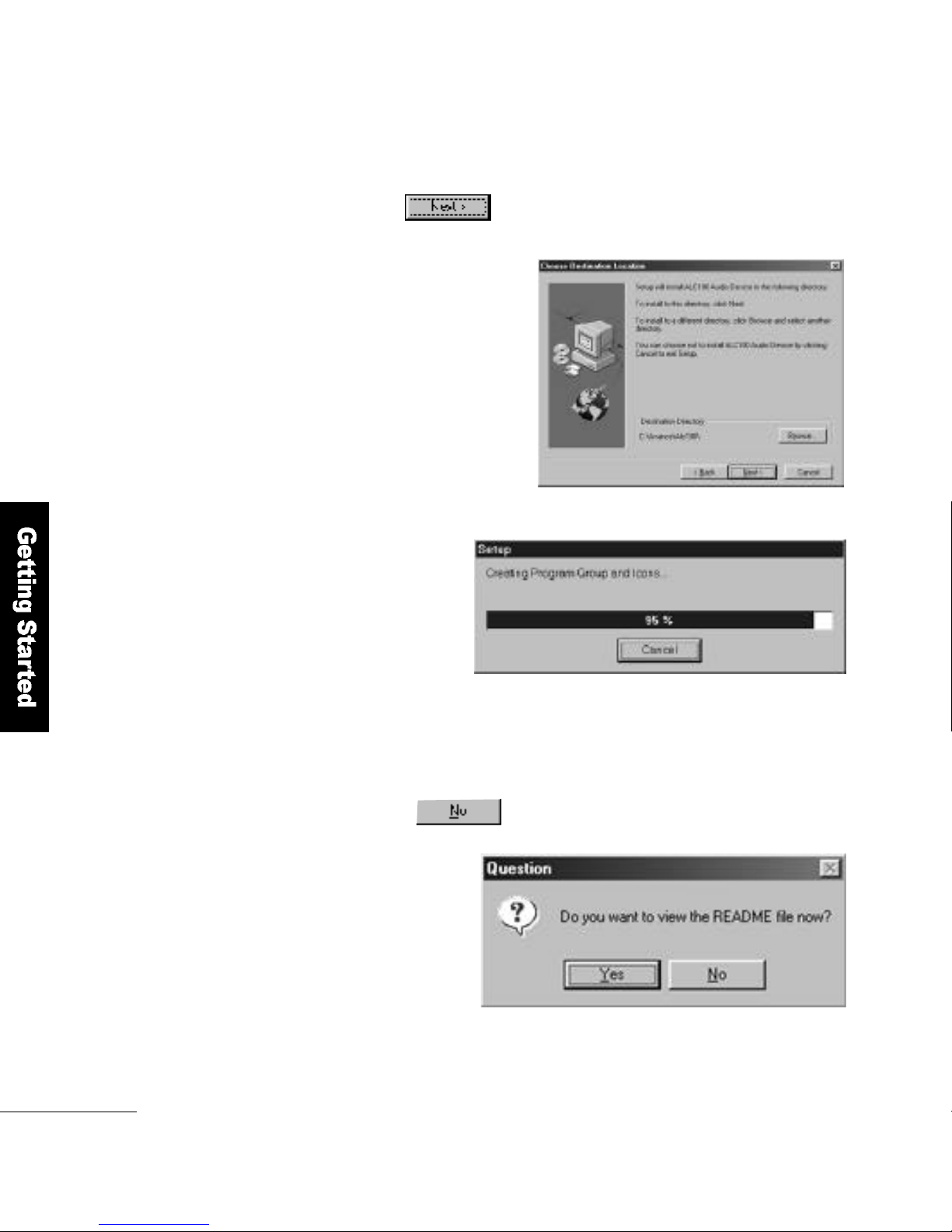
Specify the directory to which the application has been copied
and click the b u t t o n .
1 6
If you want to see the sound setup details, click Yes.
If not, click the b u t t o n .
1 7
Setup Process
Page 35
Getting Started
3 5
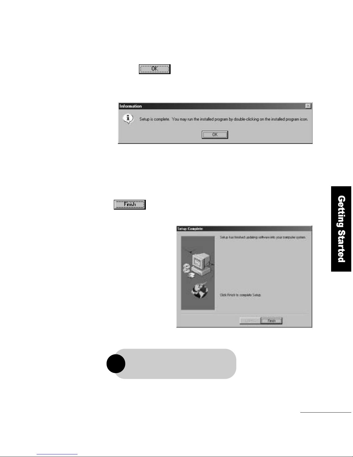
For a trouble-free driver installation,
please be sure to restart the computer.
!
Click the button to confirm driver installation.
1 8
When the entire installation is complete, click the
b u t t o n .
1 9
Page 36
3 6
Getting Started
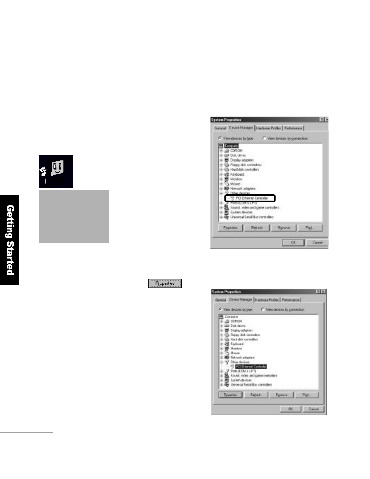
How to Install the Network Driver
Make sure that the Other Devicesof System Properties includes a P C I
Ethernet Controller.
If a PCI Ethernet
Controller exists, that
means the network
driver is not installed yet.
Choose PCI Ethernet Controller
and Click b u t t o n
1
Page 37
Getting Started
3 7
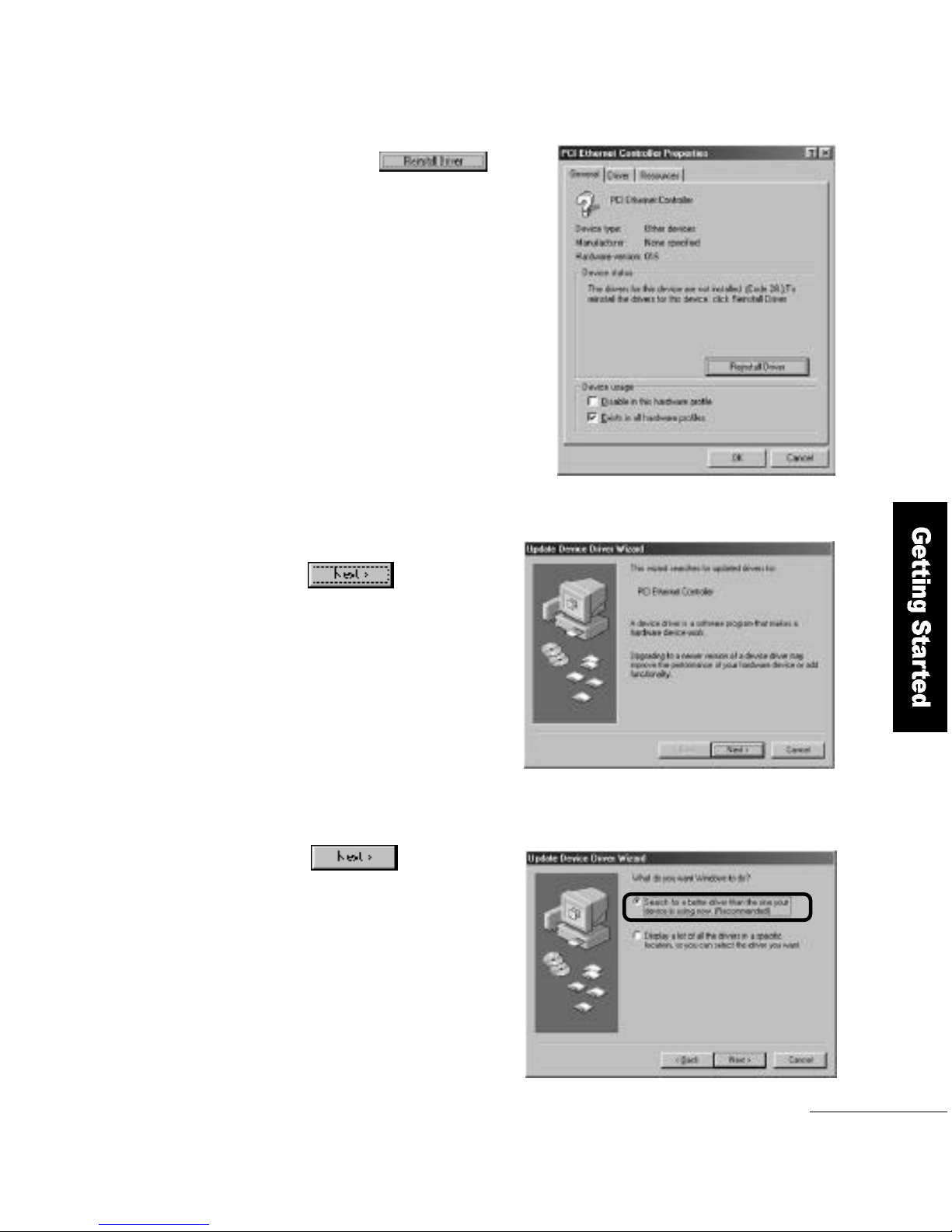
Click the b u t t o n
in the PCI Ethernet controller
p r o p e r t i e s.
2
If the Update Device Driver Wi z a r d
window appears, click the
button.
3
Select Search for a better driver than the only your device is
using now (Recommended) and click the
b u t t o n .
4
Page 38
3 8
Getting Started
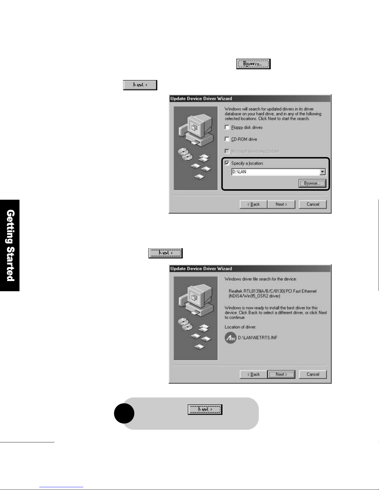
Select the location to search. Click the b u t t o n
to specify the driver′s location and then click the
b u t t o n .
5
If the device name for the driver you want to install matches,
click the b u t t o n .
6
When you click the button,
the file copy will begin.
!
Page 39
Getting Started
3 9
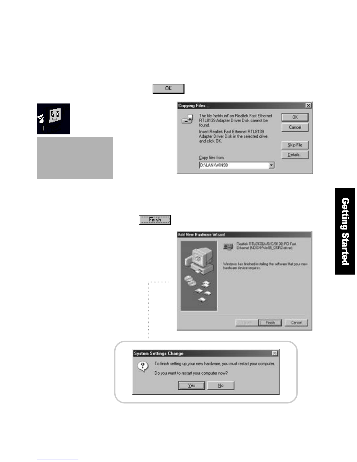
During installation,
the computer may need
the Windows 98 CD. So,
please have the CD ready.
If the computer looks for r tl8 1 3 9 . s y sduring
installation, specify the D :\L a n\w i n 9 8 folder
and click the b u t t o n .
7
When the driver installation is complete,
click the button to restart the computer.
8
Page 40
4 0
Getting Started
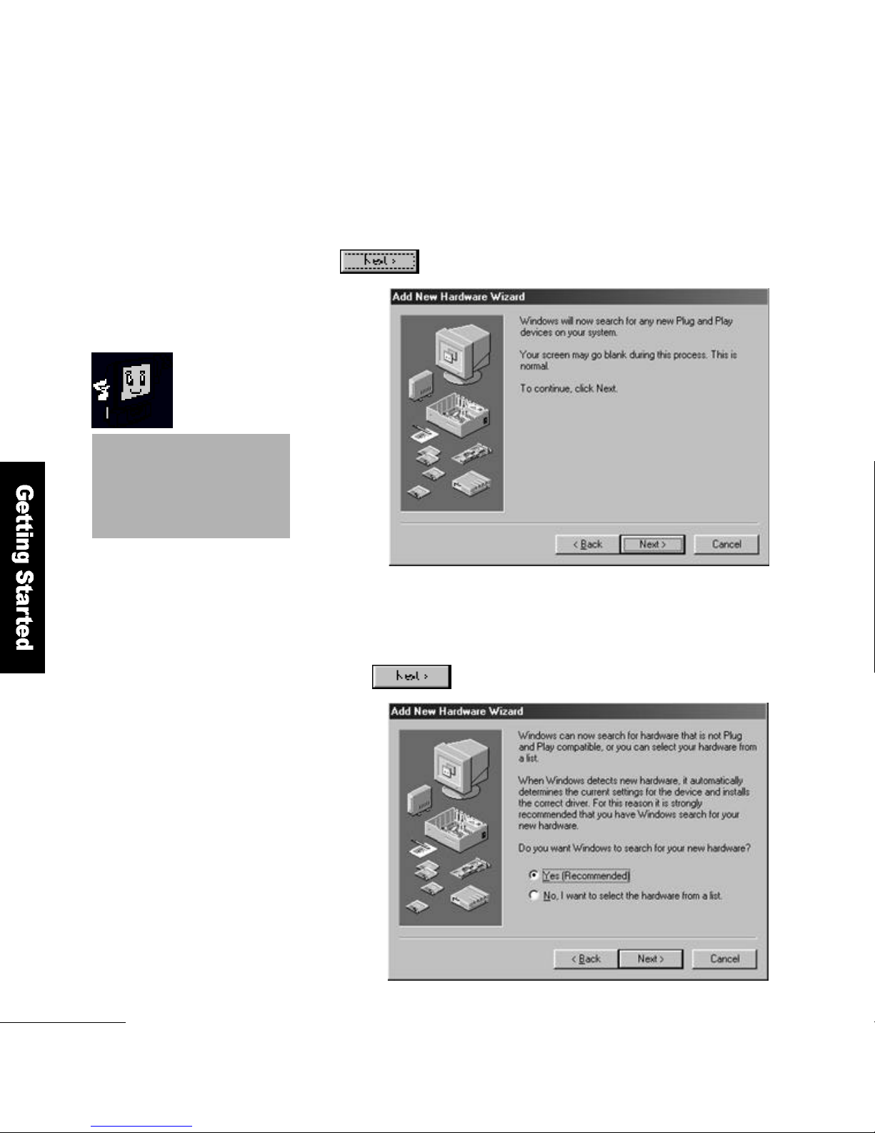
How to Install an AMR modem
To search for a driver in Add New Hardware Wi z a r d,
click the b u t t o n
Select Search for a suitable driver for my device (Recommended)
and click the b u t t o n .
1
The AMR modem is an option.
You have to have an AMR
modem card installed to
install a driver for it.
Page 41
Getting Started
4 1
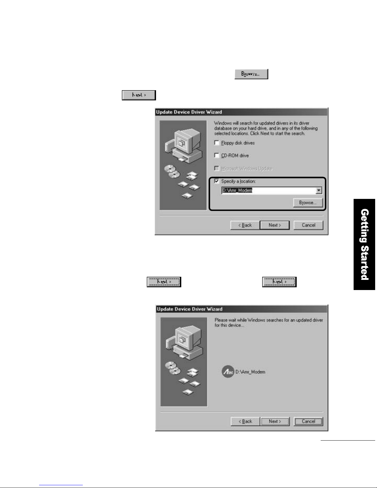
Select the location to search. Click the
button to specify the driver′s location and then click the
b u t t o n .
2
If the device name for the driver you want to install matches,
click the button. When you click the button,
the file copy will begin.
3
Page 42
4 2
Getting Started
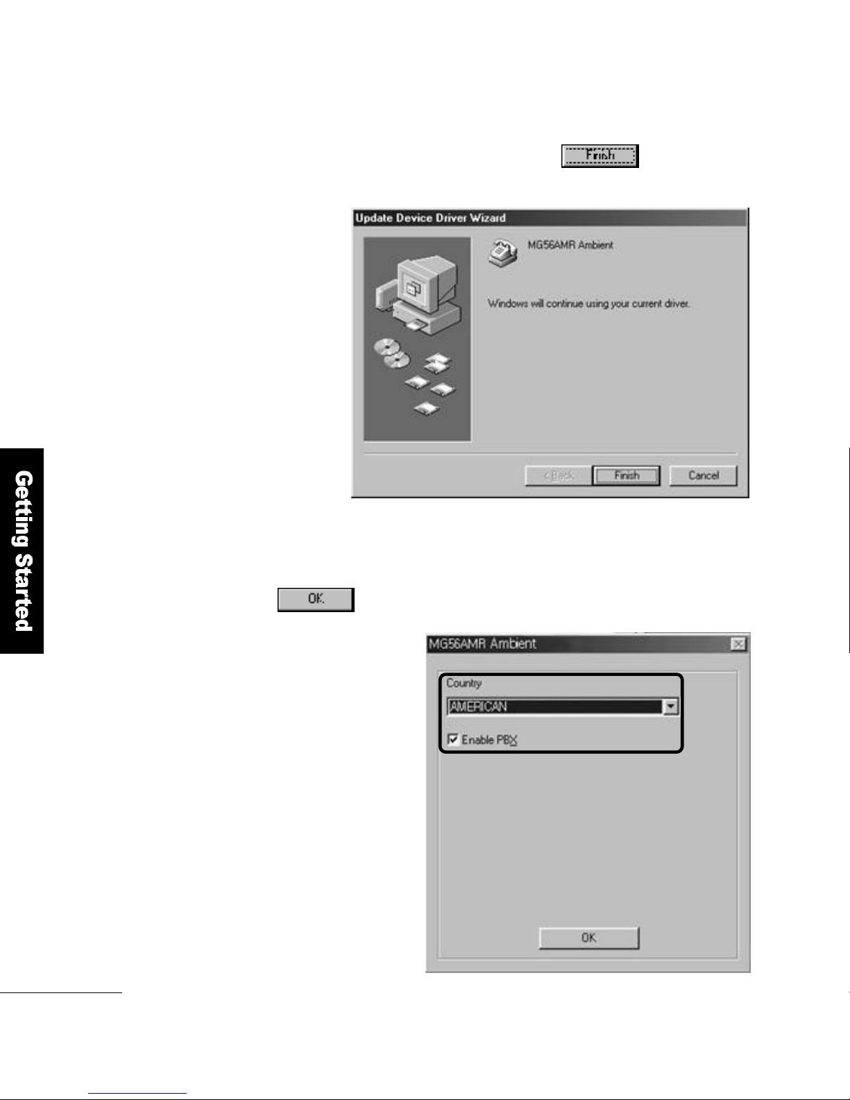
When the driver copy is complete, click the b u t t o n .
This completes the A M Rmodem driver installation.
4
Select in Add Country, Enable PBX and click the
b u t t o n .
5
Page 43
Getting Started
4 3
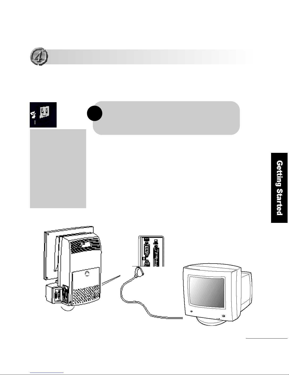
1. To use an external monitor, you must have the FLATOP VGA
driver installed.
2. Turn off FLATOP when you connect the video connector into an
external monitor
!
Using an External Monitor
Using an External Monitor
Connect the video connector on the back of FLATOP to the
external monitor.
This section describes how to connect an external monitor to your
F L ATOP computer.
As the FLATOP LCD
monitor has adopted
TFT (Thin Film Transistor)
technology to 16.7 million
colors and 1024 x 768
resolution, you can enjoy
a vivid screen quality
without using an
external monitor.
External monitor
Vi d e o
connector
Page 44
4 4
Getting Started
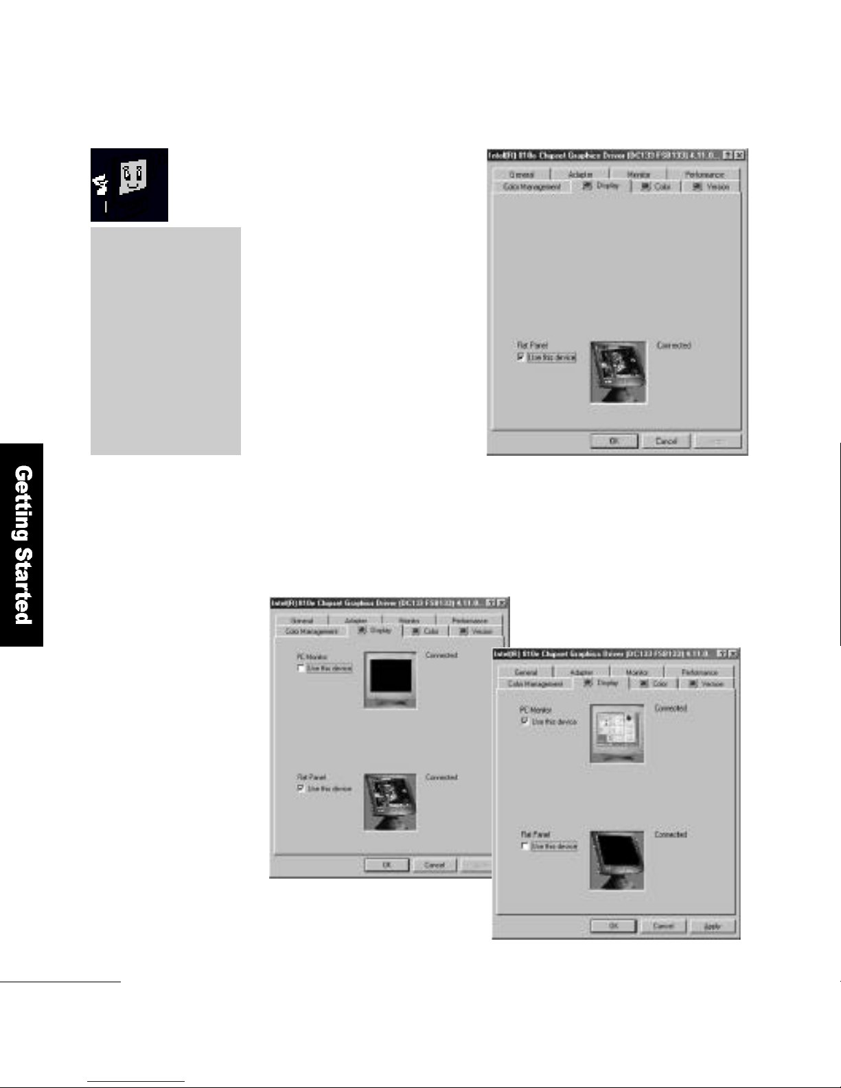
If you connect an external
monitor without turning off
your FLATO P, the computer
will not be able to find the
external monitor as shown in
the diagram.
Once the external monitor is found, you can choose between
the LCD panel (Figure 1) and external monitor (Figure 2), or both.
▲(Figure 1) LCD panel selected
▼(Figure 2) External monitor
s e l e c t e d
LCD technology
FLATOP has adopted
Black Matrix technology
to give it an excellent
screen quality. You can
clearly recognize
the difference in quality
when you compare
FLATOP with other
p r o d u c t s .
Page 45
Getting Started
4 5
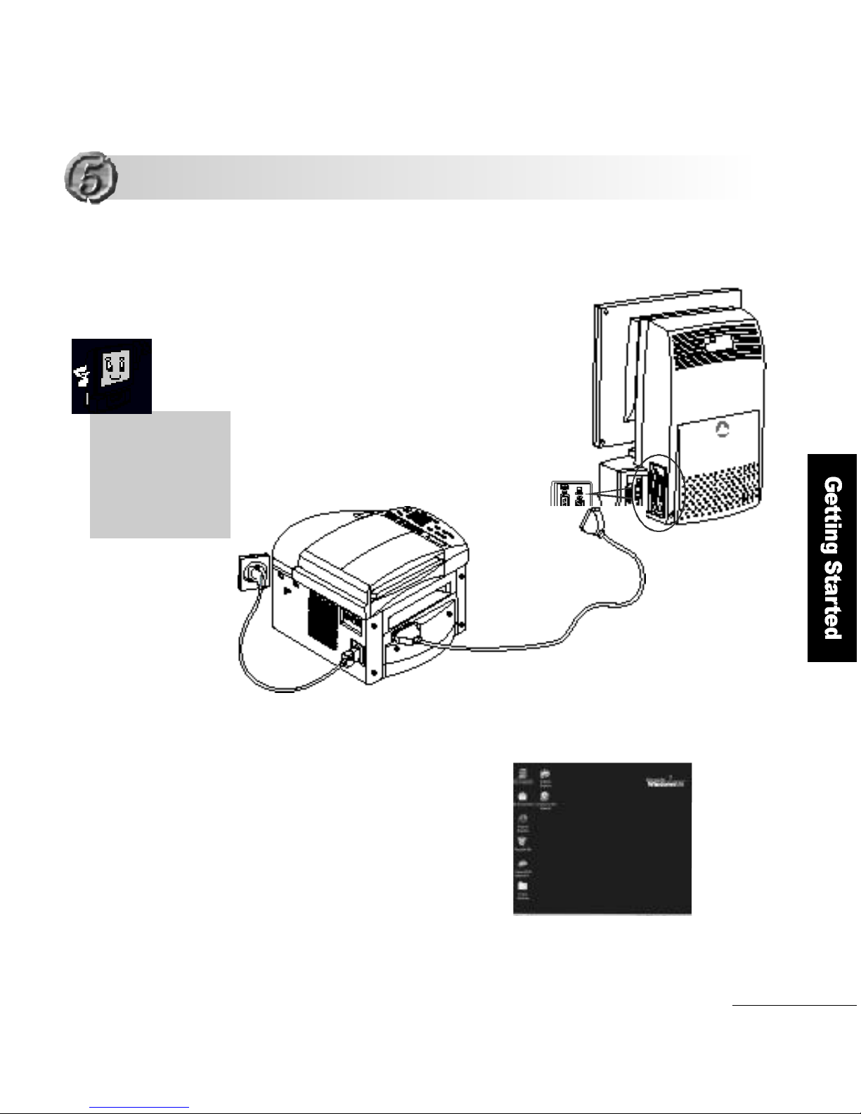
Connect the printer cable to
the print port of the computer.
When the connection is
established, first turn on
the printer and then FLATO P
to start Windows 98.
1
2
Make sure that
your computer is
turned off before
you begin the
i n s t a l l a t i o n .
Installing a Printer
Installing a Printer
Page 46
4 6
Getting Started
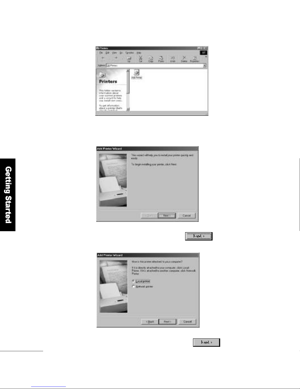
Double-click theMy Computericon. Open
the Printer folder and run Add Printer.
The Add Printer Wi z a r dbegins.
Click the b u t t o n .
3
4
Make sure that the printer is connected
and click the b u t t o n .
5
Page 47
Getting Started
4 7
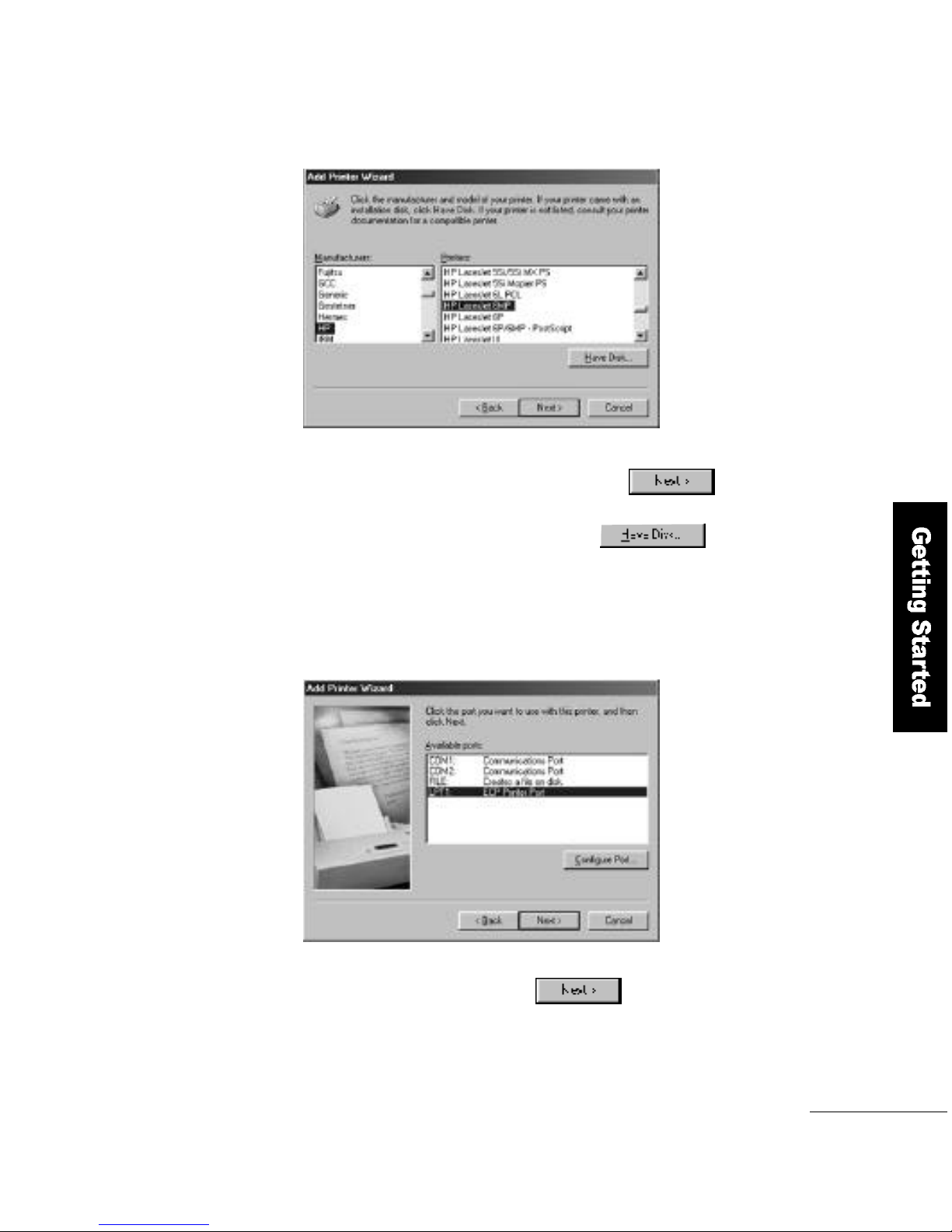
Select the LPT1 and click the
b u t t o n .
7
Select the manufacturer and model name,
and click the button.
If you have an installation disk,
click the b u t t o n .
6
Page 48
4 8
Getting Started
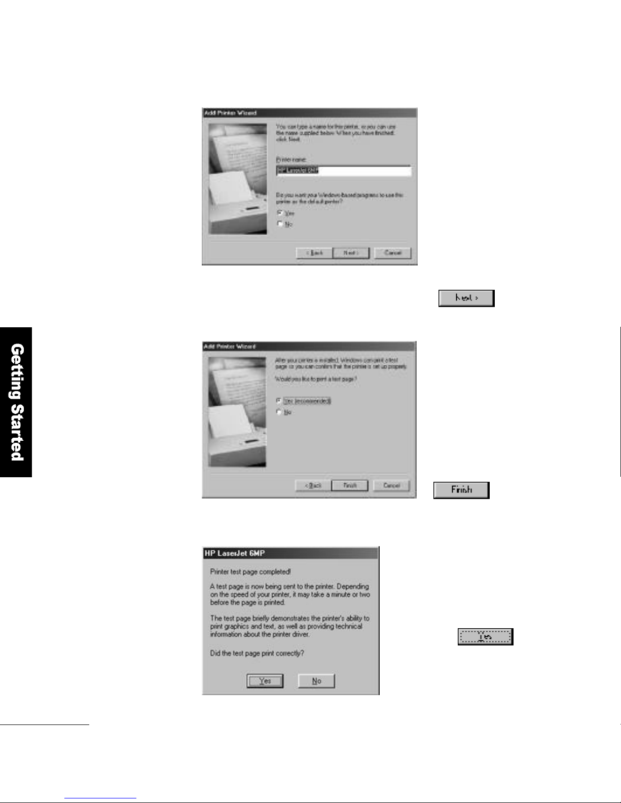
In the Test Page Print
w i n d o w, select Ye s
and click the
b u t t o n .
Type the printer name you want
and click the b u t t o n .
8
9
Check the print quality
and click the b u t t o n .
This completes the printer setup.
1 0
Page 49
Getting Started
4 9
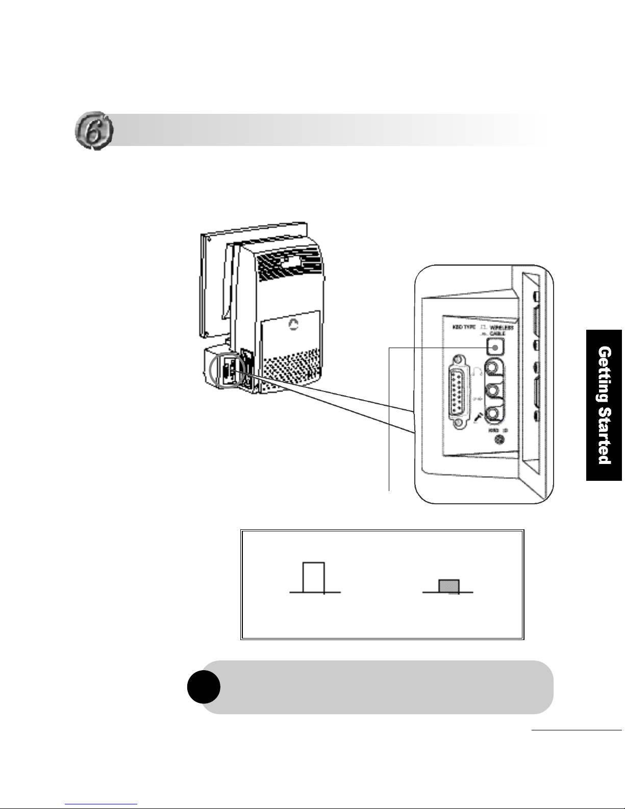
To connect a wired keyboard and a mouse, turn off the computer and set the
selection switch for wire d / w i reless keyboard and mouse to Wi red Use.
FLATOP provides for a wired PS/2 keyboard and mouse by default,
but you can choose to use a wireless keyboard and mouse if preferred.
!
Using a Wired Keyboard and a Mouse
Using a Wired Keyboard and a Mouse
Wireless Use
Wired Use
Selection switch for wired/wireless of
keyboard and mouse
Page 50
5 0
Getting Started
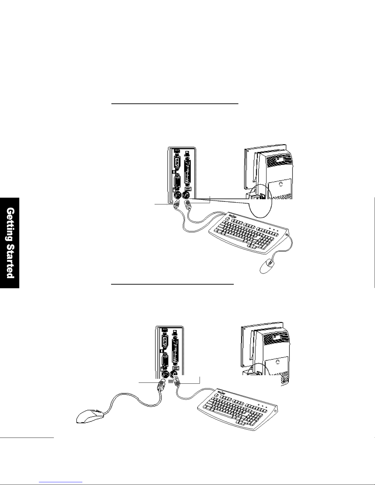
K e y b o a r d
c o n n e c t o r
Mouse connector
Connecting the mouse to the FLATO P
Connect the mouse to the FLATO P. and connect the keyboard cord of the
two cords from the keyboard to the keyboard socket of FLATO P.
2
Connecting the mouse to the keyboard
Connect the two keyboard cords to the two sockets for keyboard and mouse
in the computer. And then connect the mouse to the keyboard.
1
Two Methods to Connect Wi red Keyboard s
K e y b o a r d
c o n n e c t o r
Mouse connector
Page 51
Getting Started
5 1
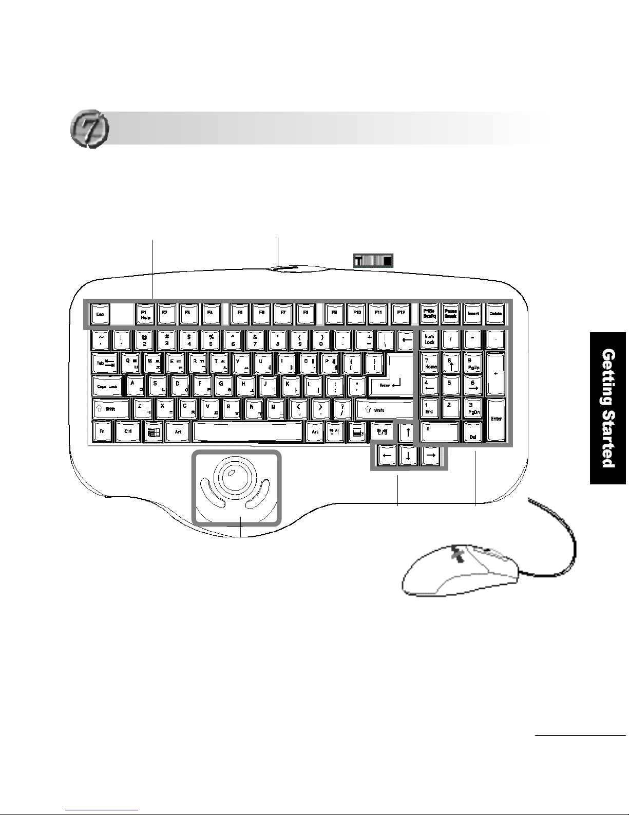
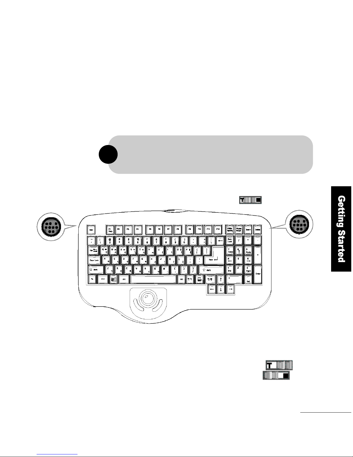
Function keypad
IR radiation
Selection switch for trackball/mouse
Number keypad
Cursor keypad
(arrow keys)
The wireless keyboard used for FLATOP provides a high space
utilization with 5m operation distance and 30°operation angle.
■H ow to use the key b o a rd ba t t e ry
F L ATO P′s wireless keyboard uses DC 3V. The life of the battery spans
about 3 months (depending on the keyboard operation time).
When the keyboard is not in use, it automatically converts to
the power saving mode to reduce wasting the battery.
Tr a c k b a l l
Using a Wireless Keyboard and a Mouse
Using a Wireless Keyboard and a Mouse
Page 52
5 2
Getting Started
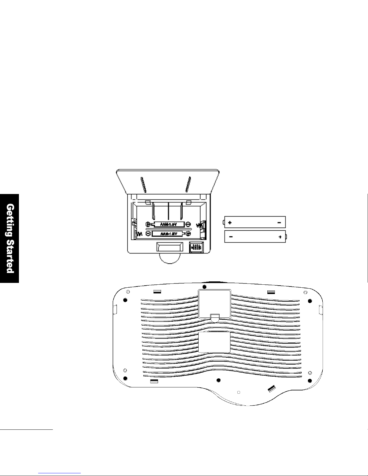
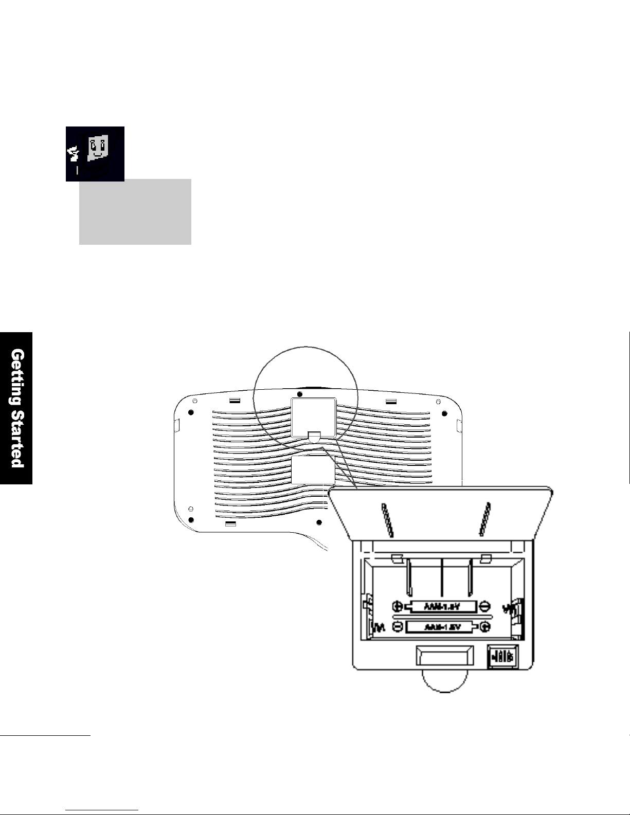
Battery Inner
B a t t e r y
C o v e r
➊
➊
Changing the Battery
1. The keyboard uses 2dry batteries of DC 1.5V and AA size.
2. Turn the computer upside down and open the battery cover.
Insert the batteries according to the + and - poles.
3. Use batteries from the same supplier for higher eff i c i e n c y.
4. Changing 2dry batteries at the same time will help the battery last
l o n g e r
Page 53
Getting Started
5 3
Selection switch for
t r a c k b a l l / m o u s e
Make sure that the computer is turned off before you connect the mouse.
You cannot connect two mouses at the same time.
■ Selection s w i t ch for tra ck b a l l / m o u s e
To use the trackball, move the switch so that ″T″is seen
To use the mouse, move the switch so that ″M″is seen
!
Using the Mouse
F L ATO P′s wireless keyboard has two bus-type mouse sockets on its right
and left sides. You can connect the mouse to either of the two sockets
w h i c h e v e r, is most convenient.
➋
➋
Page 54
5 4
Getting Started
■H ow to set an ID
Turn the keyboard upside down, open the battery cover and you will see
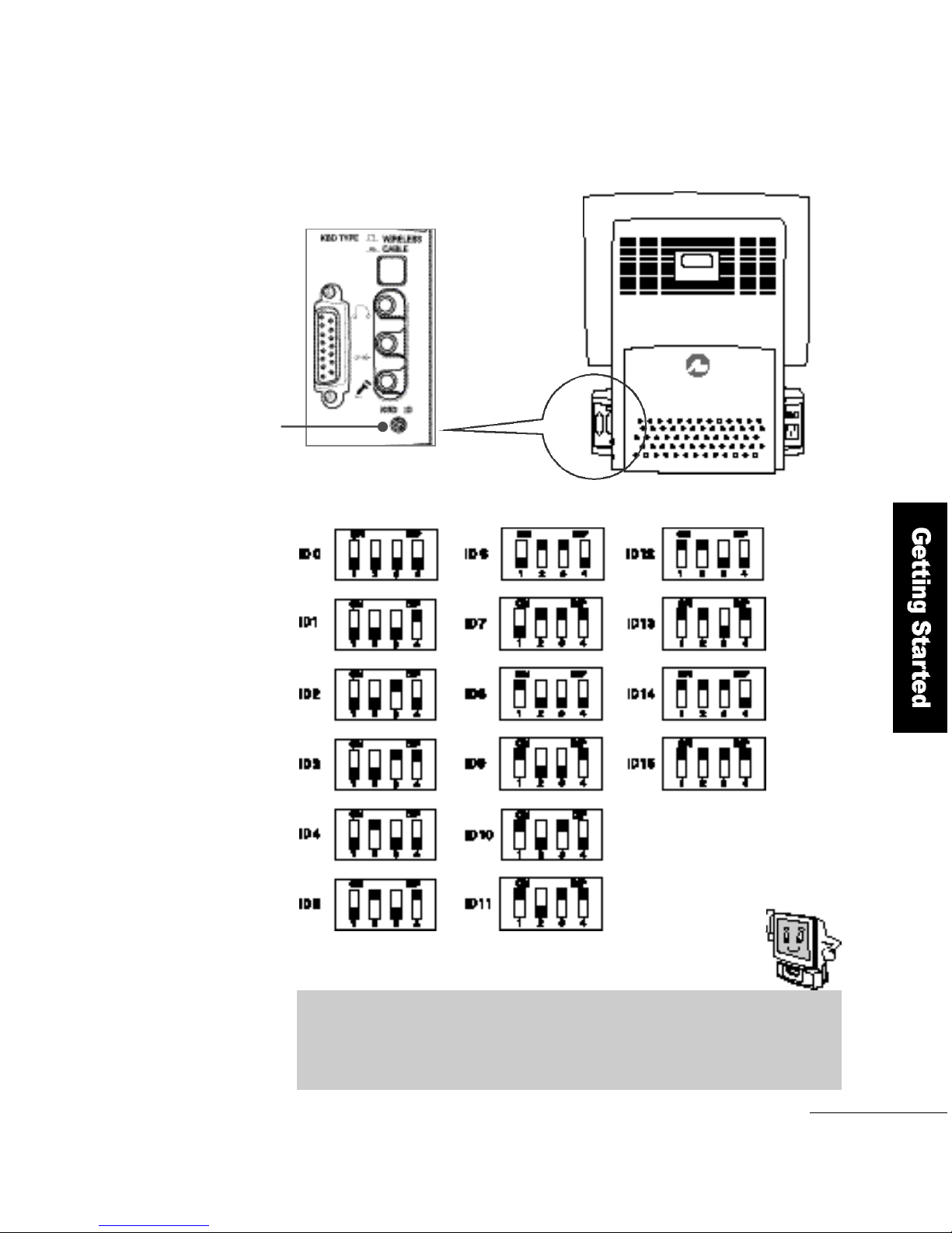
ID setting jumpers. You can use as many as 16 IDs from 0 to 15.
Set the jumpers according to the following table.
Keyboard Bottom
Battery Cover
Remove the batteries
before you set the
keyboard ID
ID setting
j u m p e r s
Setting the Keyboard ID
When two or more FLATO P′s are used with wireless keyboards,
d i fferent keystrokes could be input to your FLATO P. So, set a unique ID
for your keyboard to ensure uninterrupted operation.
➌
➌
Page 55
Getting Started
5 5
Wireless keyboard
ID reset button
If you set an ID for the wireless keyboard and press the reset button on the
back of the computer, the ID will be changed.
Page 56
5 6
Advanced Operations
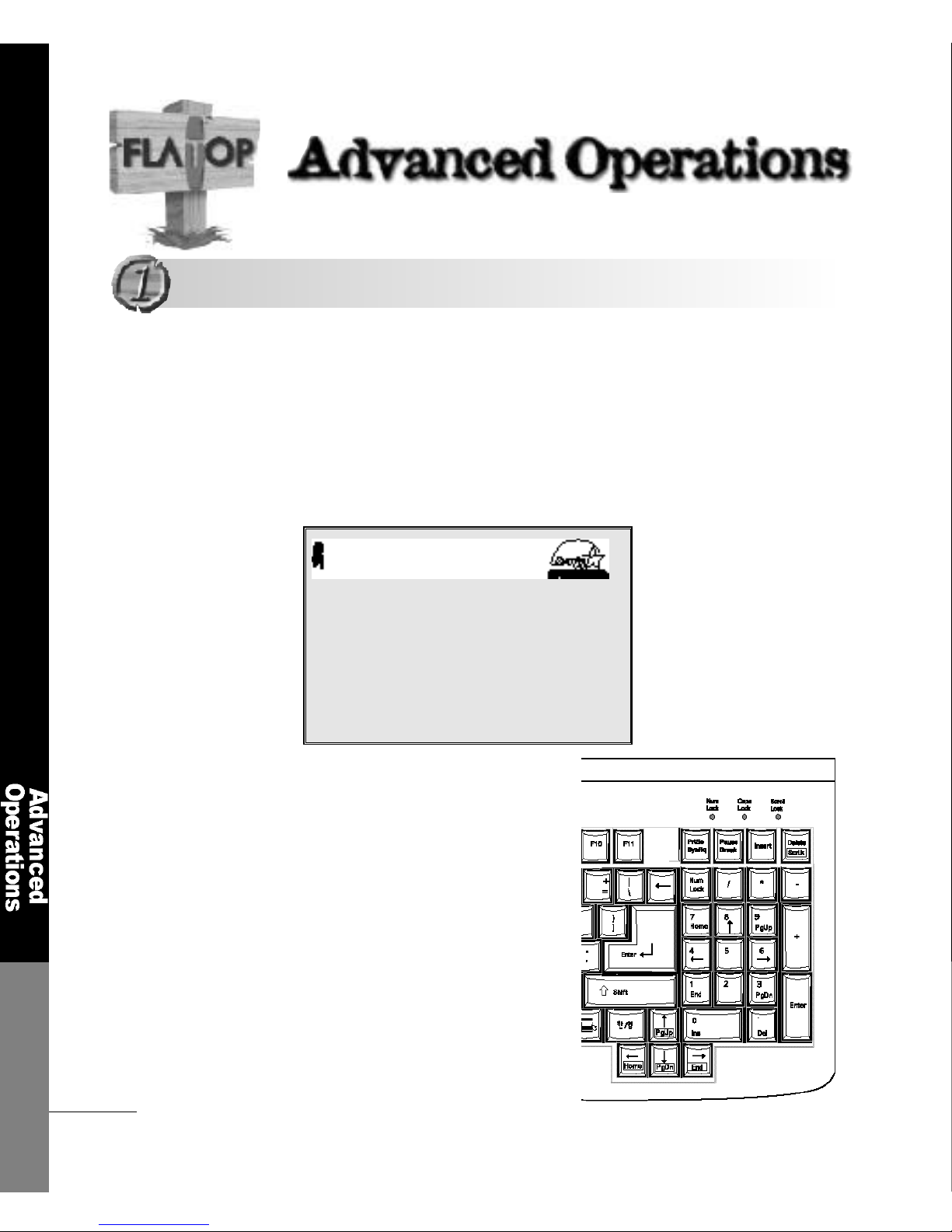
To Enter the System Setup
While the computer is initializing,
you can enter the system setup by
using the <DEL> key
The system setup re p resents how you set the computer′s hard w a re
composition in CMOS. The computer checks the savings in CMOS
every time it starts.
If there is discrepancy between the system setup and the hard w a re
components, you will see error messages. In this case, you have to
modify the CMOS setup according to the new enviro n m e n t .
Number keypad
Award Modular BIOS V6.00PG, An Energy Star Ally
Copyright(C) 1984-1999, Award Software, Inc.
6 F 8 1 0 - 0 A
Award Plug and Play BIOS Extention V1.0A
Copyright (C) 1999, Award Software, Inc.
Detecting IDE drives.......
Entering the System Setup
Entering the System Setup
Page 57
Advanced Operations
5 7
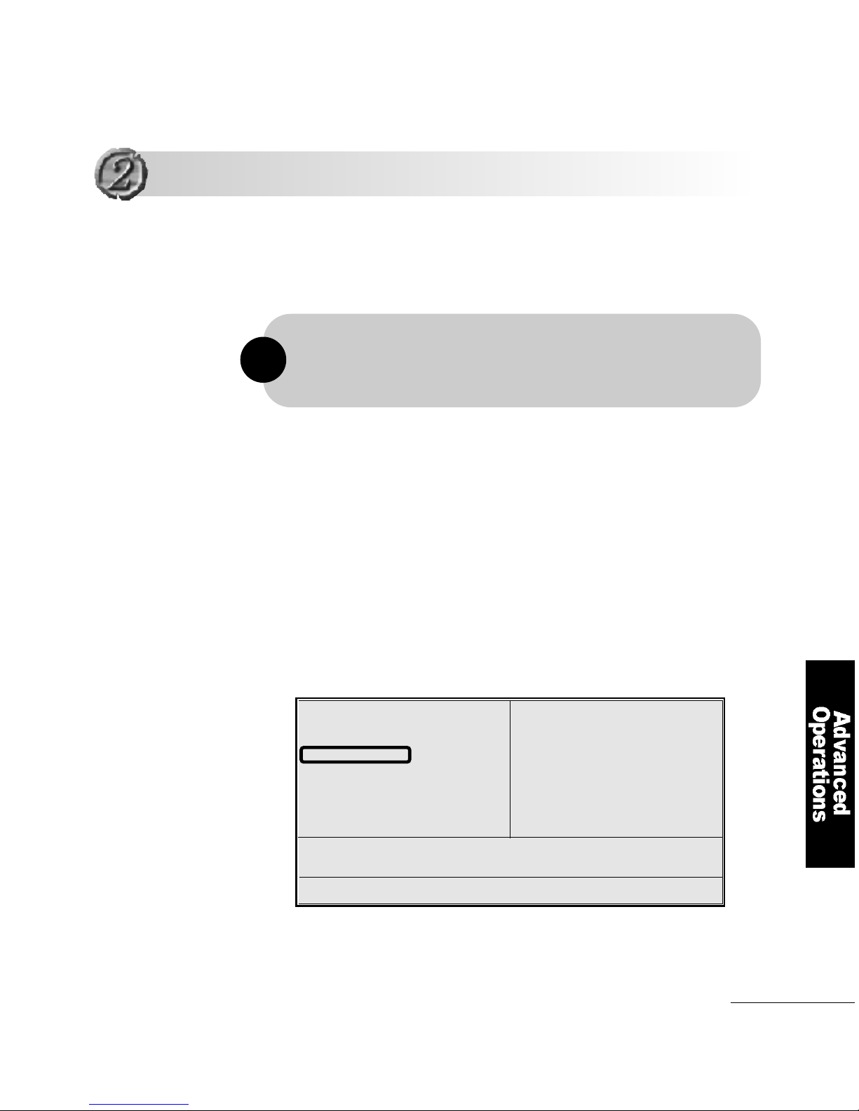
You can modify the BIOS setup to start the computer by using
the keyboard
CMOS Setup Utilty-Copyright(C) 1984-1999 Award Software
CMOS Setup Utilty-Copyright(C) 1984-1999 Award Software
1
Turning the power on using the Keyboard
Turning the power on using the Keyboard
After you power up the system, the BIOS message appears on the
screen and the memory count begins.
After the memory test, the following message will appear on the
s c r e e n .
Press DEL to enter setup.
In CMOS Setup′s primary screen, use the arrow keys to move to
Integrated Peripheralsand press E n t e r.
Standard CMOS Features
Advanced BIOS Features
Advanced Chipset Features
Integrated Peripherals
Power Management Setup
PnP/PCI Configurations
Pc Health Status
Frequency/Voltage control
Load Optimized Defaults
Set Supervisor Password
Set User Password
Save & Exit Setup
Exit Without Saving
ESC : Quit F5 : Menu in BIOS ↑↓ : Select Item
F10 : Save & Exit Setup
Time, Date, Hard Disk Type...
You can start the computer without pressing the power button, provided that
the computer is in standby mode and that the computer′s power cord is
connected to a wall outlet
!
Page 58
5 8
Advanced Operations
ESC : EXIT F1 : General Help
F7 : Optimized Defaults
• D i s a b l e d: default setting
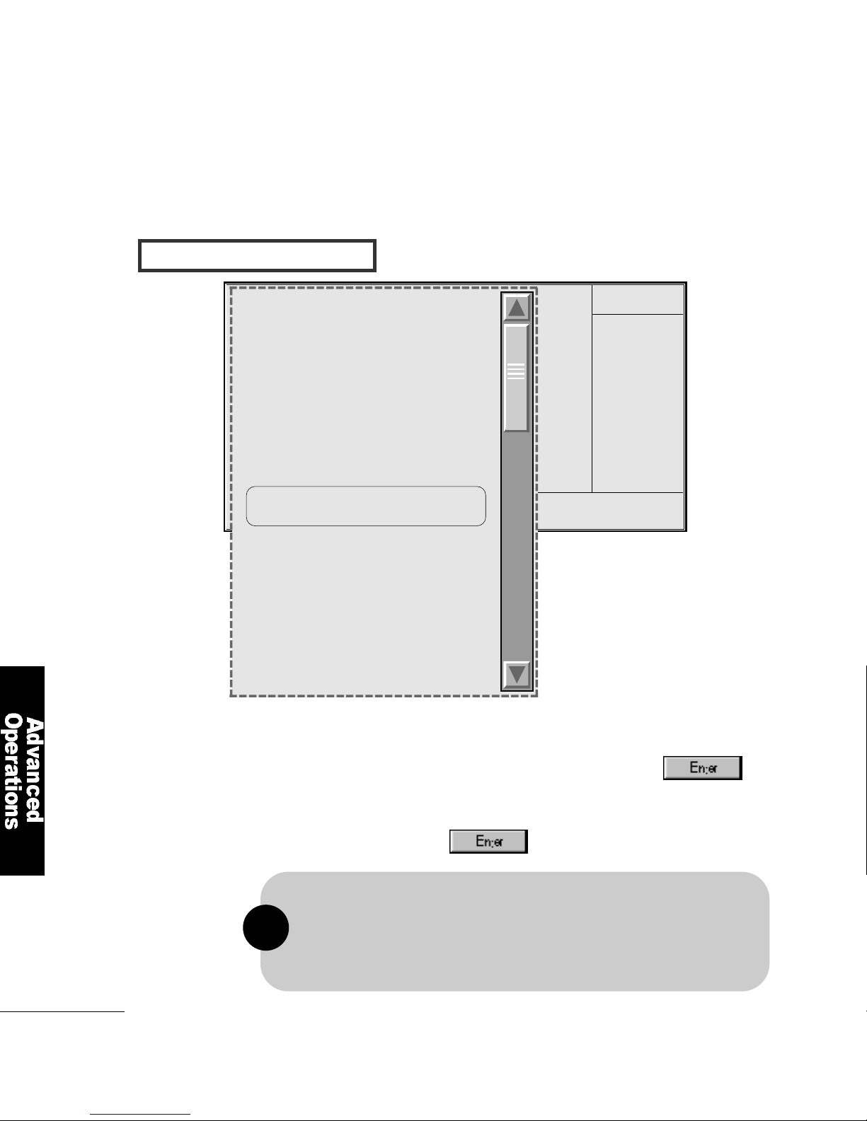
•P a s s w o r d: When this option is Selected, move the Cursor to the
KB Power On Passwordfield and press
.
Enter your password. You can enter up to characters.
Type in exactly the same password to confirm,
the press
.
I N T E R G ATED PERIPHERALS
2
Move to Keyboard/Mouse Power On
Item Help
Menu Level
CMOS Setup Utilty-Copyright(C)
1984-1999 Award Software
Integrated Peripherals
On-Chip Primary PCI IDE E n a b l e d
On-Chip Secondary PCI IDE E n a b l e d
IDE Primary Master PIO A u t o
IDE Primary Slave PIO A u t o
IDE Secondary Master PIO A u t o
IDE Secondary Slave PIO A u t o
IDE Primary Master UDMA A u t o
IDE Primary Slave UDMA A u t o
IDE Secondary Master UDMA A u t o
IDE Secondary Slave UDMA A u t o
USB Controller E n a b l e d
USB Keyboard Support E n a b l e d
Init Display First PCI Slot
AC97 Audio E n a b l e d
AC97 Modem D i s a b l e d
Keyboard/Mouse Power On D i s a b l e d
KB Power On Password E n t e r
KB Power On Hot Key C t r l - F 1
Onboard FDC Controller E n a b l e d
Onboard Serial Port 1 3 F 8 / I R Q 4
Onboard Serial Port 2 2 F 8 / I R Q 3
UART2 Mode Select N o r m a l
RxD, TxD Active H i , L o
IR Transmission Delay E n a b l e d
Onboard Parallel Port 3 7 8 / I R Q 7
Parallel Port Mode E C P + E P P
EPP Mode Select E P P 1 . 7
ECP Mode Use DMA 3
PWR Lost Resume State Keep Off
Game Port Address D i s a b l e d
Midi Port IRQ 5
X
X
X
X
X
The power button will not function once a keyboard password has been set in
the KB Power On Passwordfield. You must type the correct password to
power-on the system. If you forgot the password, power-on the system and
then remove the battery. Wait for a few seconds and install it back before
power-on the system.
!
Page 59
Advanced Operations
5 9
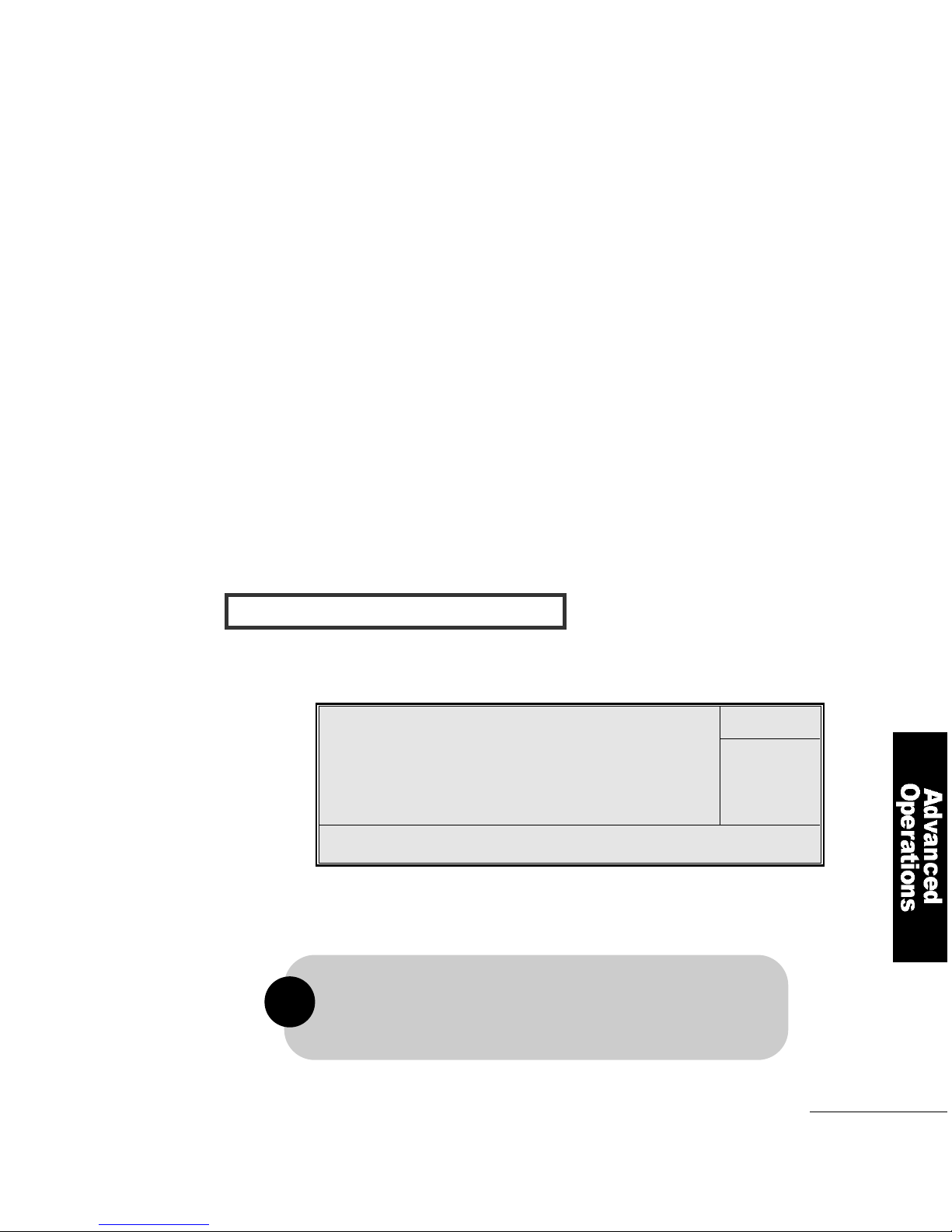
FREQUENCY / VOLTAGE CONTROL
•Hot Key : When this option is selected, move the cursor to the
KB Power On Hot Keyfield to select a function Key
you would like to use to power-on the system.
The options are from Ctrl+F1 to Ctrl+F12.
•Mouse Left : If you select this option, you can turn on the system by
double-clicking the mouse left button.
•Mouse Right : If you select this option, you can turn on the system by
double-clicking the mouse right button
•Any Key : If you select this option, you can turn on the system by
pressing any key.
•Keyboard98 : If you select this option, you can turn on the system using
the ″Wake Up ″button on the Windows 98 keyboard.
•Button Only : If you select this option, you can turn on the system only
by pressing the power button (default).
CMOS Setup Utilty-Copyright(C) 1984-1999 Award Software
CPU Frequency Control
You can choose CPU Clock Ratio processor rate. The following
options are provided; x3, x3.5, x4, x4.5, x5, x5.5, x6, x6.5.
↑↓ Move Enter : Select Item +/-/PU/PD : Value F10 : Save ESC : EXIT F1 : General Help
F5 : Previous Values F6 : Fail-safe Defaults F7 : Optimized Defaults
Item Help
Menu Level
Auto Detect DIMM/PCI Clt E n a b l e d
Spread Spectrum E n a b l e d
Host CPU/DIMM/PCI Clock D e f a u l t
CPU Clock Ratio X 3
The frequent ratio of some processors has been fixed by
the manufacturer, therefore you don′t need to over clock them.
If you are using this kind of processor, please ignore this field.
!
Page 60
6 0
Improved Computer Performance
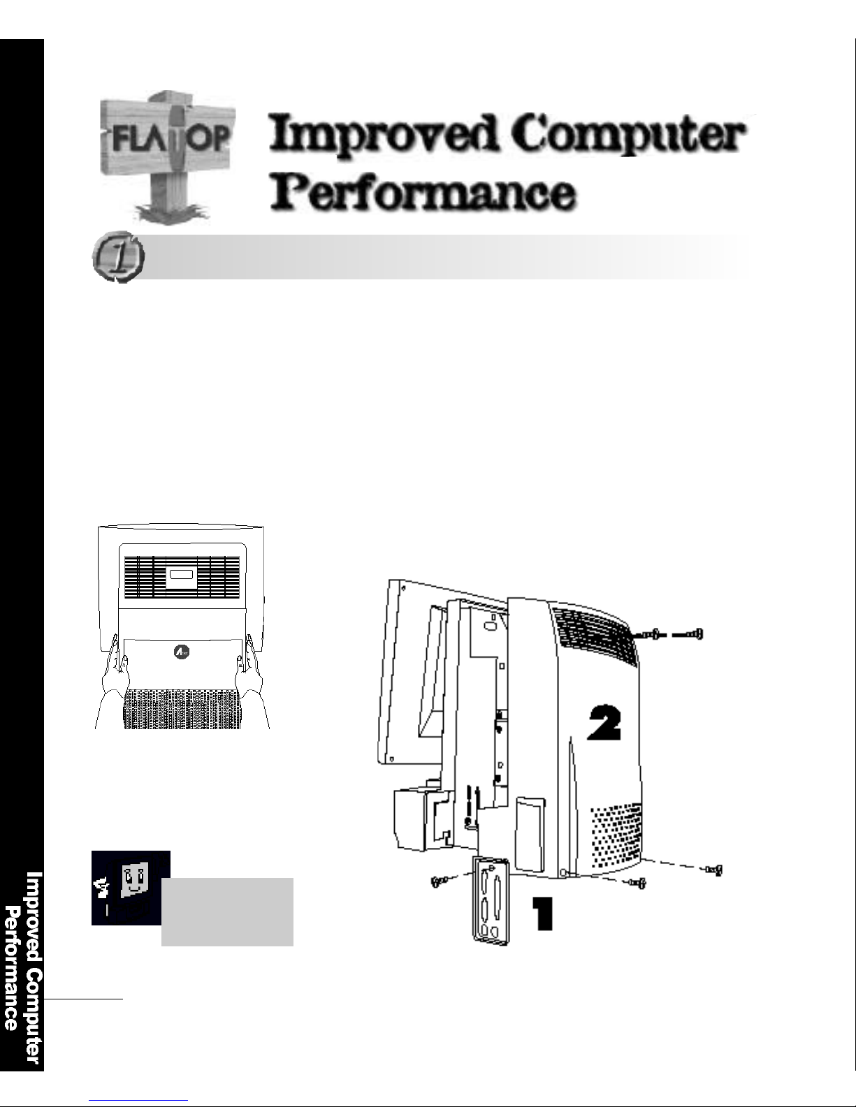
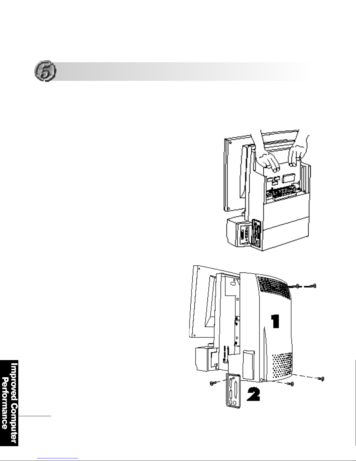
Put the computer on a clean place
Remove the screws.
Pull the cover softly
(Forced pulling could cause damage to the LCD panel).
Disconnect the computer from the power before you remove the
computer cover. Removing the cover with the computer turn e d
on could cause damage to computer components due to fire or
a short-circ u i t .
Opening the ComputerCover
Opening the Computer Cover
Open the computer
according to the
n u m b e r .
Page 61
Improved Computer Performance
6 1
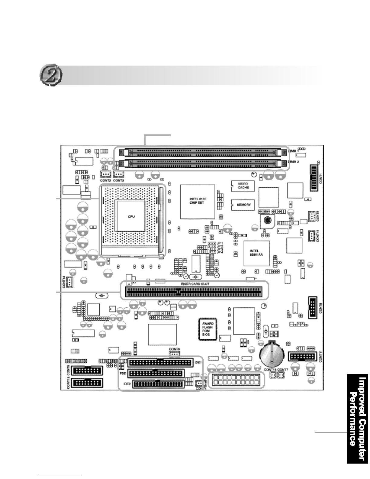
When you scale the computer up, check the related parts.
Composition of the Mainboard and Connectors
Composition of the Mainboard and Connectors
F C - P G A
CPU socket
Riser card slot
Floppy disk connector
CD-ROM connector
Hard disk connector
Power connector
Memory socket (DIMM)
•
•
•
Page 62

6 2
Improved Computer Performance
Cont 1 LCD interface cable connector (for LCD output)
Cont 2 FAN 1: CPU Cooling fan ′spower connector (permitted changing with Cont 3)
Cont 3 FAN2: External radiator fan′spower connector (permitted changing with Cont 2 )
Cont 4 Cooling fan′spower connector
Cont 5 Inverter Connector
Cont 6 IR connector
Cont 7 Internal Microphone connector
Cont 8 Serial Port 2 connector
Cont 9 External serial port, parallel port, VGA port connector
C o n t 11 USB, Ethernet port connector
C o n t 1 2 Sound, keyboard and mouse connector
C o n t 1 3 Line in connector
C o n t 1 4 Left speaker connector
C o n t 1 5 MiCom Test (Don′t used)
For correct connection, check the mainboard′sconnector information
Connector Functions
1. Make a record of the information on the connection status before you
remove the connectors.
2. Connect the hard disk drive, floppy disk drive and CD-ROM drive
connectors according to their directions.
!
Page 63
Improved Computer Performance
6 3
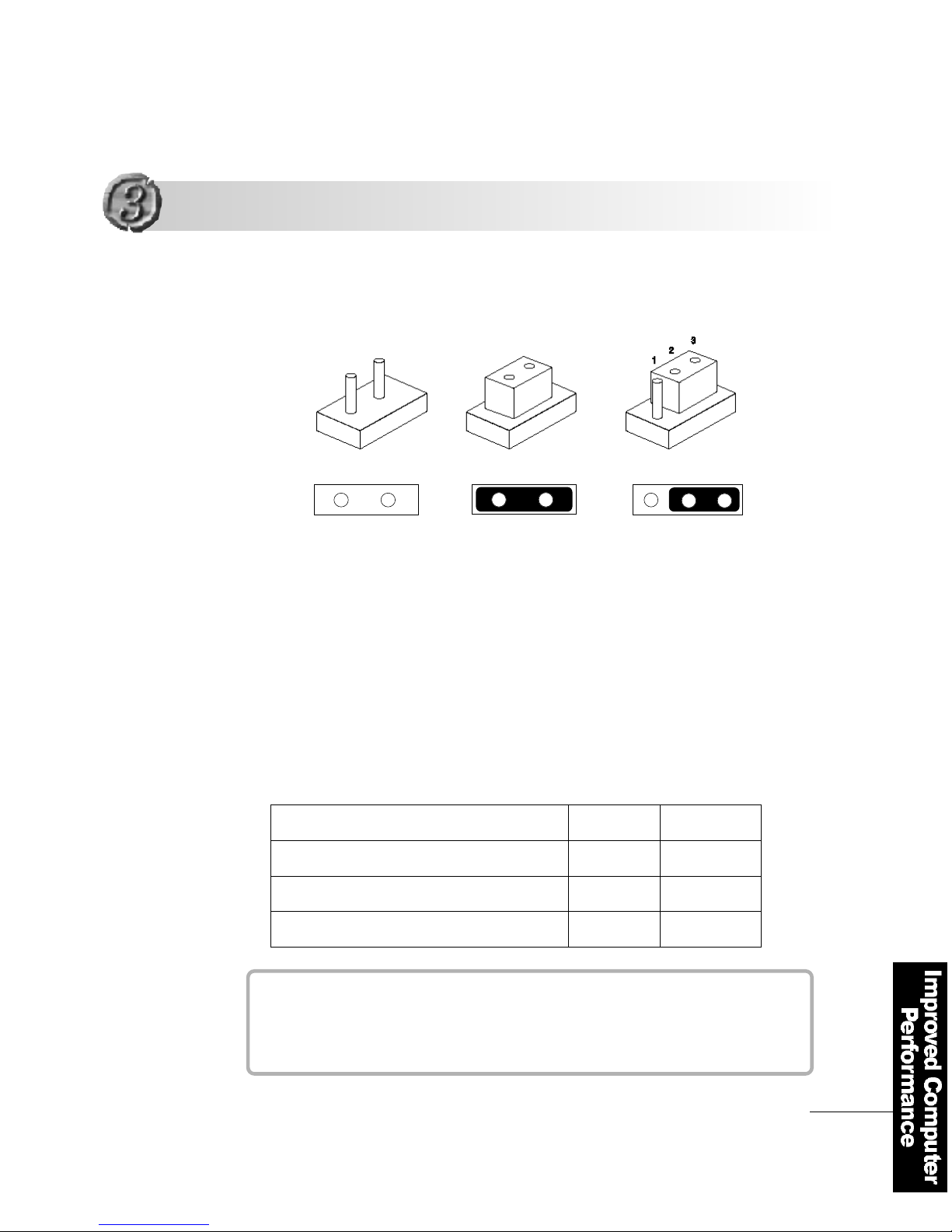
Since AF8 senses the CPU speed automatically, you don′t have to set
the jumpers. The AF8 supports PPGA CELERON CPU and FCPGA
PENTIUM ⅢC P U .
The AF8 mainboard supports the system bus clock from 66Mhz to 133Mhz
(the default is 100Mhz).
Set the jumpers according to the CPU clock(set in the closed mode).
O P E N
C l o s e d
Number 2 and 3 closed
M H z
Celeron CPU 66 MHz
P e n t i u mⅢ CPU ″E″Type 100 MHz
P e n t i u mⅢCPU ″E B″Type 133 MHz
J P 1
2 - 3
1 - 2
1 - 2
J P 2
2 - 3
2 - 3
1 - 2
Improving the CPU perf o r m a n c e
Improving the CPU perf o r m a n c e
Jumper Setting
Jumper Setting for CPU Speed
( Re m oved in the mass pro d u c t i o n )
Page 64
6 4
Improved Computer Performance
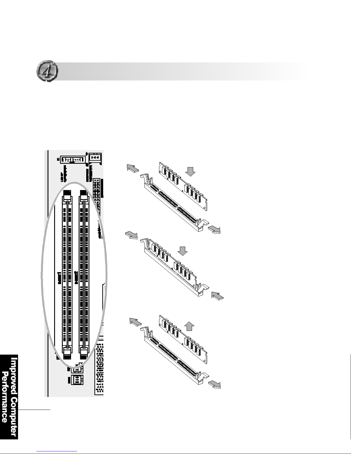
The AF8 uses 168 pin memory modules called
″DIMM (Dual In-line Memory Module)″.
It supports a maximum 512MB.
Pull the lock-in tabs outward to
remove the memory module
Pull the two lock-in tabs outwards
at the both ends of the memory
s o c k e t .
Insert the memory module into the
socket perpendicularly in a
rightwards direction.
1. Inserting the memory module
2
1
1
2
1
2
Expanding the Memory
Expanding the Memory
2. R e m oving the memory module
Page 65
Improved Computer Performance
6 5
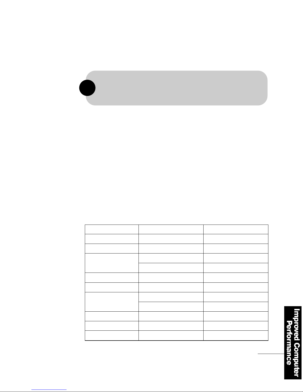
FLATOP supports PC-100 and special PC-133 standard memory.
* FLATOP cannot use PC-66 memory. A combination of Celeron CPU and PC-66
memory could cause abnormal operation in the memory.
We don ′t recommend this combination.
!
■C a u t i o n s
1. As memory is vulnerable to static electricity, be careful in inserting and
removing the memory modules.
2. Check the memory module type before you install the new memory
m o d u l e .
※ Specifications for the memory module used for this product
Memory type : 168 pin DIMM (SDRAM)
Speed : PC-100
Capacity : 64MB, 128MB
Total Memory Capacity
3 2 M
4 8 M
6 4 M
8 0 M
9 6 M
1 2 8 M
1 9 2 M
2 5 6 M
3 2 M
3 2 M
3 2 M
6 4 M
6 4 M
6 4 M
6 4 M
1 2 8 M
1 2 8 M
1 2 8 M
DIMM 1
DIMM 2
1 6 M
3 2 M
1 6 M
3 2 M
6 4 M
6 4 M
1 2 8 M
5 1 2 M 2 5 6 M
2 5 6 M
Page 66
6 6
Improved Computer Performance
Open the computer cover and insert
the card using both hands
Make sure that the card is correctly
inserted into the slot and fasten the
c a r d′s bracket with a screw.
Close the cover and fasten
it with screws
F L AT O P′s m a i n b o a rd can accommodate additional
2 PCI cards or 1 AMR card and 1 PCI card .
1
2
3
Installing cards in the Expansion Slot
Installing cards in the Expansion Slot
Page 67
Improved Computer Performance
6 7
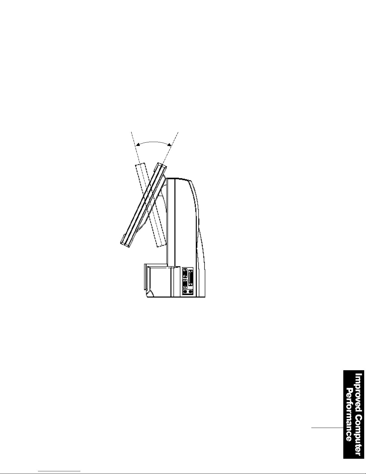
■Adjusting the FLATOP LCD Monitor
You can adjust FLATO P′s
TFT LCD monitor in the vertical
range of -5 ~ +25 °. To change
its vertical angles, hold both
sides of the panel and move it
up and down.
3 0°
Page 68
6 8
T r o u b l e s h o o t i n g
This section describes universal problems that could happen to your
F L AT O P. If you encounter difficulties and problems in using this pro d u c t ,
first refer to this section. You can gain detailed explanations by calling
our help desk at 82-2-2190-5050.
Q1
A
One of my applications does not operate normally. Why?
Check the followings
1. Is there enough memory to run the application?
2. Is the application is designed for the current operating system?
3. Is the necessary device driver installed?
4. Does the application have a problem when it runs on another
c o m p u t e r ?
If you encounter an error message while using the application, refer to the
manual that comes with the application. If you still have problems, contact
the branch where you purchased the product or our help desk.
Page 69
Troubleshooting
6 9
Q2
A
I connected an external monitor, but why are the monitor screens
overlapping and unstable?
F L ATO P′s TFT LCD uses 1024 x 768 resolution. This resolution is
applied to the external monitor. Therefore the screen could be distorted
or tremble. Adjust the external monitor′s resolution according to the
following procedure.
1. Refer to the monitor ′s User Manual and check the supported
r e s o l u t i o n s .
2. Select Di s p l a y from the Control Panel.
3. Select Settings tap in the Display Properties.
4. Set the resolution that the monitor supports and click Ye s
If the above procedure doesn′t solve the problem, check that the
F L ATOP video driver is correctly configured in the Display Properties
Q3
A
I reinstalled Windows 98. Why do the sound, VGA, and LAN cards
m a l f u n c t i o n ?
To use FLAT O P′s sound, VGA, and LAN cards after reinstallation, install
all the drivers provided by the manufacturer again. You can download
those drivers from FLATO P′s website at www. f l a t o p . c o . k r.
※ Please refer to ″Installing drivers″on Page 18
Page 70
7 0
T r o u b l e s h o o t i n g
Q5
A
Why does the computer have white or colored spots on its LCD screen?
F L ATO P′s LCD contains about 1 million pixels and bad pixels could occur.
LCDs with higher quality pixels are extremely expensive and beyond the
a ffordability of average users.
We are doing our best to minimize bad pixels. Bad pixels below a certain
level don′t affect the product.
Q4
A
The computer issues a message Keyboard error or no keyboard present
and the keyboard doesn′t function. Why?
You can use either a wired or a wireless keyboard by setting the
selection switch for wired/wireless options
Check the following
1. Check the keyboard connection.
2. Check the selection switch for wired/wireless keyboard is correctly set.
3. When the dry battery is used up, the keyboard could malfunction.
Check the battery.
4. If you are using a wireless keyboard, press the ID reset switch on the
k e y b o a r d
Page 71
Troubleshooting
7 1
Q6
A
How can I find out how to install other operating systems and drivers for
those systems?
Please refer to the FLATOP installation guide or visit our website at
w w w.flatop.co.kr for information on new operating systems and device
d r i v e r s
Q8
A
Why doesn′t my FLATOP shutdown automatically under Windows 2000.
1. Click Start and point to S e t t i n gsand then Control Panel. Run the
Power Option and select A P Mand then Advanced Power
M a n a g e m e n t. Activate the Enable APM Support .
2. Enable APM, ACPI related items in BIOS′s Power Management and
reinstall Windows 2000.
Q7
A
Why can ′t FLATOP recognize the AMR card?
After installing the AMR card, set the AC97 Audio or AC97 Modem to
E n a b l e din Integrated Peripheralsin the system BIOS.
Page 72
Page 73

Page 74

Page 75
O n e - y e a r
w a r r a n t y
C u s t o m e r′s C a r d
W a r r a n ty
:
FLATOP LCD PC
Model name :
:
: Te l . A d d r e s s
: Te l . A d d r e s s
You must present this warranty containing the date of purchase when you ask for service.
Please keep this warranty in a safe place.
1. The warranty of this product will be based on the contents in the warranty.
2. The warranty period is calculated from the date of purchase, please write down the date of purchase.
3. The warranty period lasts one year for normal use.
4. In the case of a separate agreement, the descriptions of the main agreement will be applied.
Product name
Date of Purchase
C u s t o m e r′s Name
Agency Name
:
FLATOP LCD PC
Model name :
:
: Te l . A d d r e s s
: Te l . A d d r e s s
Product name
Date of Purchase
C u s t o m e r′s Name
Agency Name
Page 76

 Loading...