

FlatfoilZ Assembly Guide
EXTRA 300, EDGE 540, LEK-TRICK & STALKER
Version 1.0
10-27-11

2
Limited Warranty
FlatfoilZ takes pride in the care and attention given to the manufacture of the components in this kit. The
company warrants replacement of any materials found to be defective for their intended use prior to their
use in the construction of the model, provided the purchaser requests such replacement within a one year
period from the date of purchase, and the part is returned, if so requested by the Company. No other
warranty, expressed or implied, is made by the company with respect to this kit. The purchaser assumes
full responsibility for the risk and all liability for personal or property damage or injury resulting from the
purchaser’s use of the components of this kit whether assembled or not.
The Company reserves the right to provide a full refund to the purchaser if the model does not perform as
advertised. Any refund is at the sole discretion of the Company.
Introduction:
Thank you for choosing one of the FlatfoilZ Profile Series airplanes. The assembly of all the
FlatFoilZ planes is very simple and requires a minimum of building skills. This Quick Start Guide is
provided for those with some building experience. The full Assembly Manual is available at 3DX
Hobbies.com.
Warning
This radio-controlled model is not a toy and, if operated inappropriately can cause serious
bodily injury and property damage. It is the buyer’s responsibility to assemble the kit correctly
and properly install the motor, radio and all other equipment. The model must always be flown in
accordance with the safety standards of the Academy of Model Aeronautics (AMA).
Recommended Power System:
The FlatFoilZ series of planes have been designed to use a 175 to 250 watt power system.
Recommended motors include the Hacker A20-20L, Scorpion 2215-18, or AXI 2217-16. The
prototypes were flown with a 1350 mAh, 3S Li-poly battery and a 25 amp ESC. Other power
systems with similar capabilities can be used. Performance will vary depending on the specific
power system selected. For information on alternate power systems please visit
http://3dxhobbies.com or your local hobby shop.
General Comments on Assembly:
While not difficult to assemble, the FlatFoilZ Series kits are intended for persons with some building
experience. As such, the instructions are presented as a simple sequence that, when followed, will
help ensure that the airframe turns out straight and light. Improperly aligned surfaces and
unnecessary weight will only hinder its performance. All the FlatFoilZ prototype wings and fuselages
were laminated using 15 minute epoxy thinned with alcohol. Apply glue and epoxy in a thin uniform
coat, using only enough to achieve a strong bond. Excess glue or epoxy will only add unnecessary
weight and will not increase the strength of your model. Trial fit all components to ensure fit and
alignment before applying any glue or epoxy. Keeping joints tight fitting will minimize the amount of
glue required and will ensure a strong bond. Use a light touch while sanding. Foam cuts very
quickly and excess pressure can limit your ability to accurately shape the foam. Take extra care not
to over sand. Avoid scratching the surface of the Depron foam.
© Copyright 2011 all rights reserved`
3
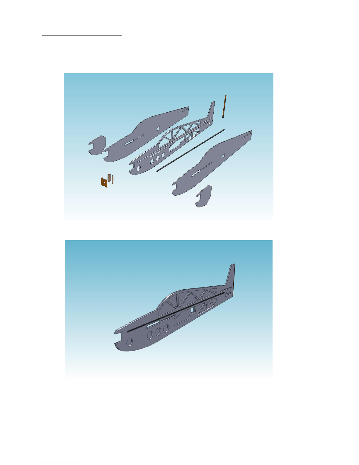
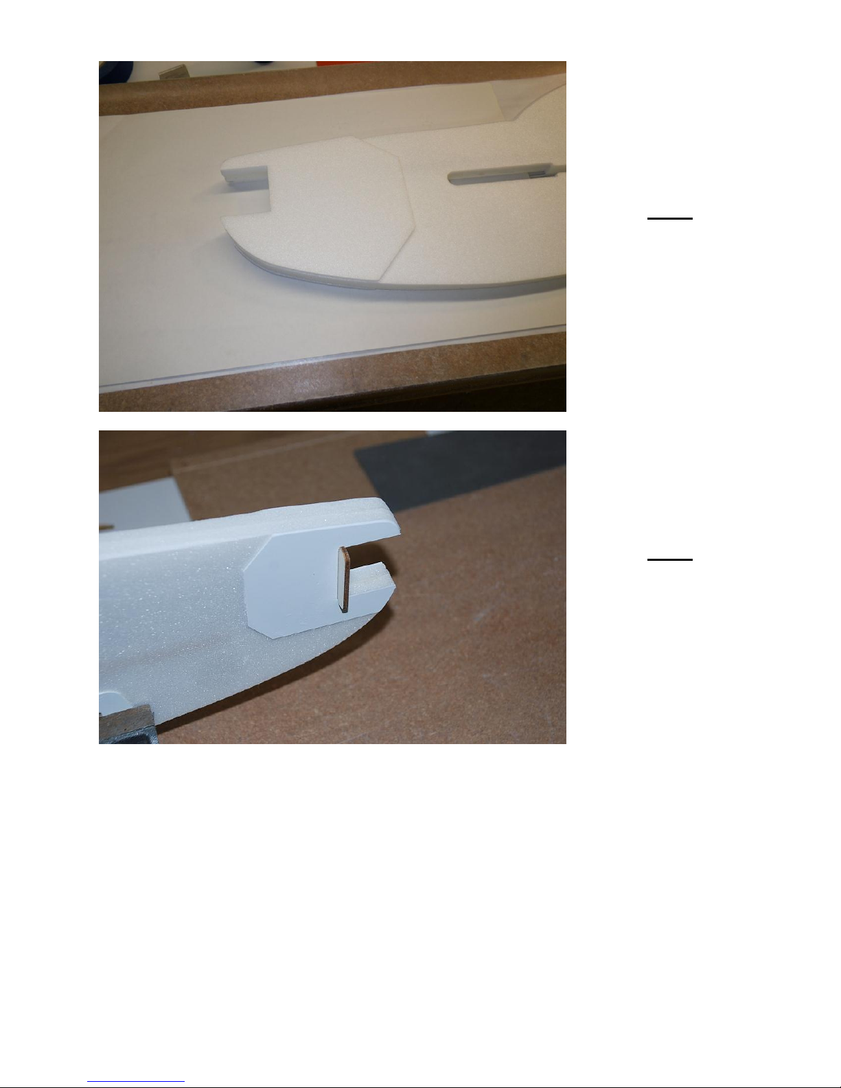
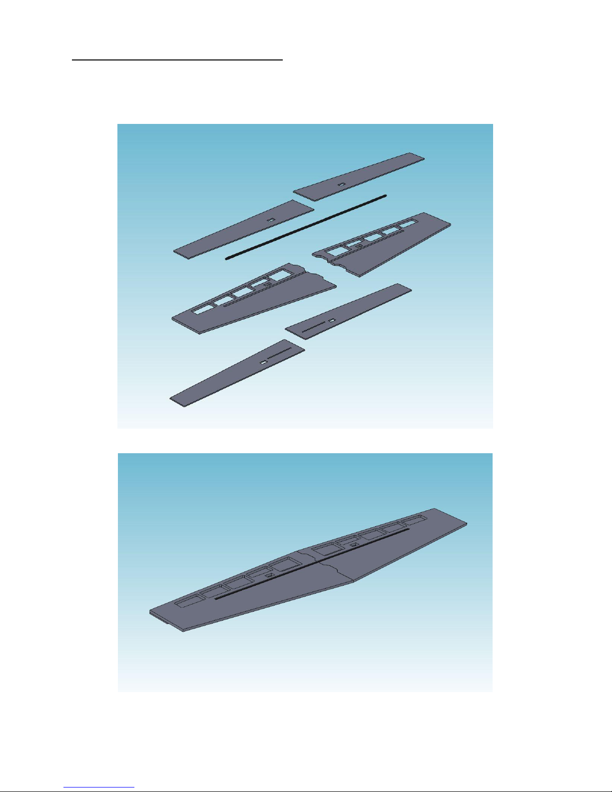
Fuselage Assembly:
Exploded View of Typical Fuselage Assembly
Fuselage with Right Skin and Carbon Fiber Spar in Place
The fuselage assembly on the FlatfoilZ NX Profile Series kits consists of a 6 mm depron laser cut
core, over which are laminated 3 mm depron skins. A 6 mm carbon tube is embedded in the 6mm
core piece.
© Copyright 2011 all rights reserved`
4
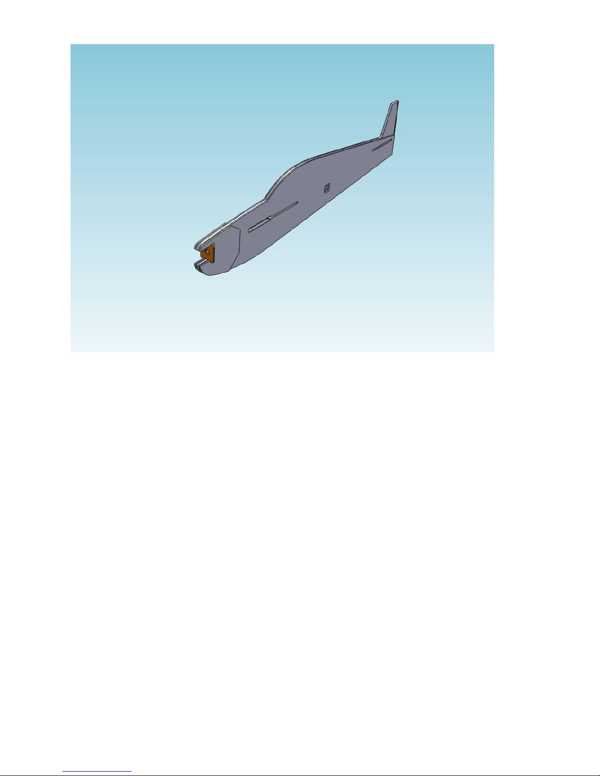
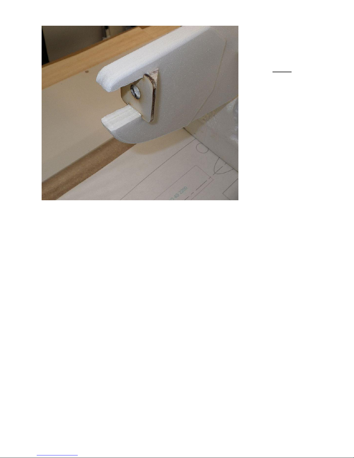
Completed Fuselage Assembly
Follow the steps in the order outlined below to ensure accurate alignment of the
components.
© Copyright 2011 all rights reserved`
5
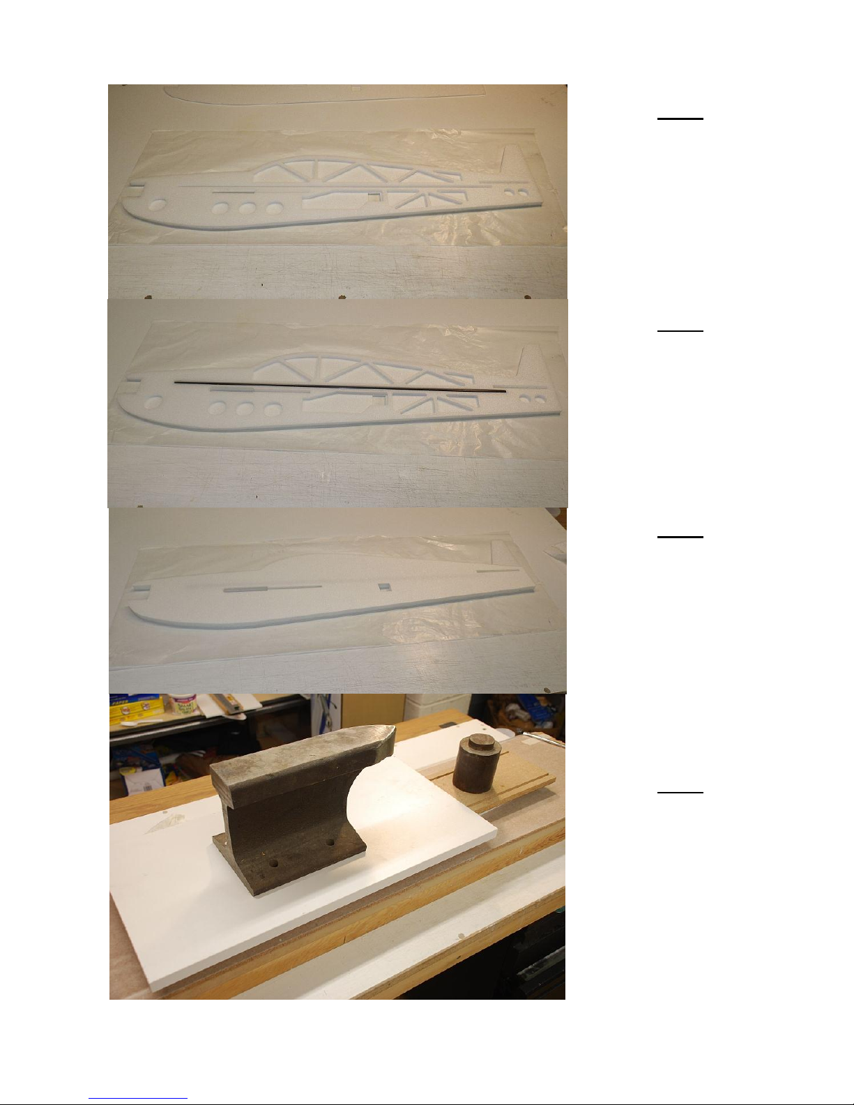
Step 1
Apply thinned 15 min
epoxy to one side of the
6mm fuselage core and
position the core on the
3mm fuselage skin .
Step 2
Apply epoxy into the
center slot in the
fuselage core and insert
the 6mm carbon tube
spar into the slot.
NOTE: Lightly sand the
surface of carbon tube
for better glue adhesion.
Step 3
Apply thinned 15 min
epoxy to the other side
of the 6mm fuselage
core and position the
other 3mm fuselage skin
over the core.
Step 4
Place the glued
assembly on a flat
building surface and
weigh down to ensure
the assembly dries flat
and true.
© Copyright 2011 all rights reserved`
6
Step 5
Glue the 3mm depron
nose doublers on both
sides of the fuselage.
Step 6
Test fit the ply motor
mount in the fuselage
opening.
© Copyright 2011 all rights reserved`
7
Step 7
Cut the balsa tri-stock
motor mount supports
to the proper length and
check their fit behind
the motor mount.
Epoxy the motor mount
and balsa tri-stock rear
supports in place
making sure that the
motor mount is square
to the fuselage.
If you would like to finish the edges of the fuselage, use your sanding block to smooth and
either bevel or round the edges approximately 1/8 inch. Sand the edges of the motor mount
and motor mount supports smooth using a sanding stick or emery board.
© Copyright 2011 all rights reserved`
8
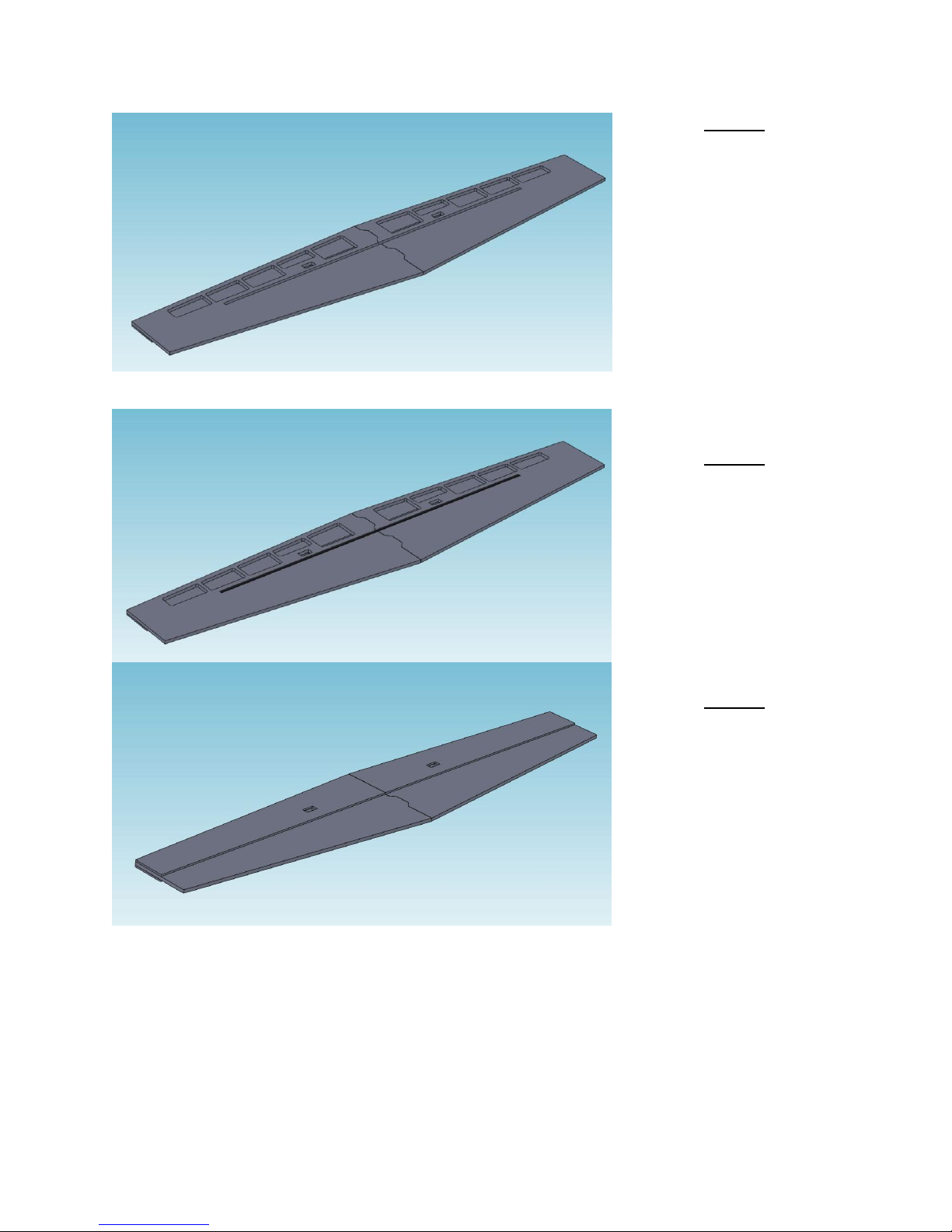
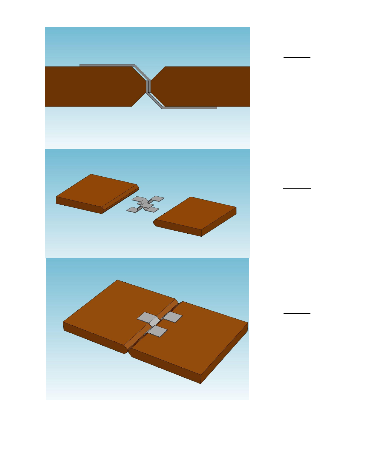
Wing Assembly and Installation
Exploded View of Typical Wing Assembly
Wing with Bottom LE Skin and Carbon Fiber Spar in Place
The fuselage assembly on the FlatfoilZ NX Profile Series kits consists of a 6 mm depron laser cut
core, over which are laminated 3 mm depron leading edge skins. A 6 mm carbon tube is embedded
in the 6mm core piece.
© Copyright 2011 all rights reserved`

9
Completed Wing Assembly
Step 8
Join the two wing cores
together using 5 minute
epoxy.
Wing Assembly:
© Copyright 2011 all rights reserved`

10
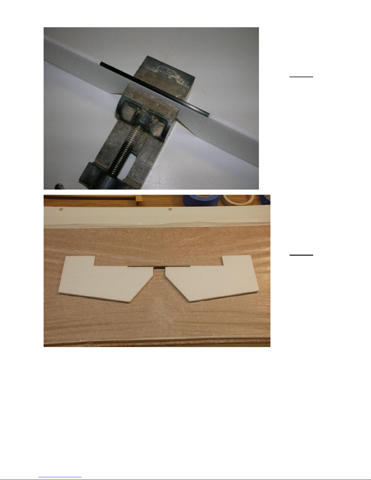
Step 9
Cut the spar slot through
the center joint.
© Copyright 2011 all rights reserved`
11
Step 10
Apply thinned 15 min
epoxy to the bottom side
of the 6mm wing core
and position the core on
the 3mm bottom LE
skins. NOTE: Test fit the
bottom LE skins on the
wing core and lightly
mark where the rear edge
is located on the wing
core. Only apply the
epoxy up to that line.
Step 11
Apply epoxy into the spar
slot in the wing core and
insert the 6mm carbon
tube spar into the slot.
NOTE: Lightly sand the
surface of carbon tube
for better glue adhesion.
Step 12
Apply thinned 15 min
epoxy to the top side of
the 6mm wing core and
position the top 3mm LE
skin over the wing core.
© Copyright 2011 all rights reserved`

12
Step 13
Place the glued assembly
on a flat building surface
and weigh down to
ensure the assembly
dries flat and true.
Step 14
After the epoxy has
cured, sand the wing LE
round.
© Copyright 2011 all rights reserved`

13
Wing/Fuselage Assembly:
Step 15
Test fit the wing in the
fuselage. DO NOT
FORCE! If the fit is
tight, gently sand the
fuselage opening to fit.
Make sure the wing is
centered on, and square
to the fuselage. With
the wing properly
aligned, tack glue it in
place with medium foam
safe CA.
Permanently glue the
wing in place by forming
a fillet from mixture of
15 or 30-minute epoxy
and micro balloons.
Step 16
Using the end of the
3/16” diameter carbon
elevator joiner, gently
create a shallow grove
in the elevator joiner
cutout.
Tail Feather Assembly:
Installing the Elevator Joiner: (Note: Not required on the Stalker)
© Copyright 2011 all rights reserved`
14
Step 17
Secure the 3/16”
diameter carbon
elevator joiner in place
with epoxy. Tip: For a
lighter joint, a mixture of
15 minute epoxy and
micro balloons can be
used.
Step 18
Cut out the foam bridge
behind the wood joiner,
between the elevator
halves.
© Copyright 2011 all rights reserved`

15
Installing the Horizontal Stabilizer Spar: (Note: Not required on the Stalker)
Step 19
Glue the 1/8” x 1/4”
balsa horizontal
stabilizer spar to the
rear of the horizontal
stabilizer
Step 20
Test fit the horizontal
stabilizer in the fuselage
and check that it fits
square to the fuselage
and wing. Glue the
stabilizer in place with
medium foam safe CA.
Step 21
Trim the rear of the
horizontal stab slot in
the fuselage. Install the
elevator and apply the
hinges. (Not required
on Stalker)
Note: See Control
Surface Hinging section
below for installing tape
hinges.
© Copyright 2011 all rights reserved`

16
Step 22
Glue the 1/8” x 1/4”
rudder post in position
using foam safe CA.
Sand the rudder post
flush with the top of the
vertical stabilizer and
with the bottom of the
fuselage. (Not required
on Stalker)
Step 23
Trim the back of the
fuselage at an angle to
match the rudder post
using your Exacto knife.
This allows clearance
for the rudder control
horn. (Not required on
Stalker)
© Copyright 2011 all rights reserved`

17
Control Surface Hinging:
Step 24
Using a sanding block,
bevel the edge of the
both mating surfaces
along the hinge line.
All the control surfaces on the prototypes were hinged with tape. Any number of schemes can be
used. However, we prefer the Over/Under method outlined below.
Making Over/Under Tape Hinges:
© Copyright 2011 all rights reserved`
18
Step 24a
Hinges are made by
overlapping 2 pieces of
tape together along the
hinge line. One side
goes on top of one
surface and the other
side goes on the bottom
of the mating surface.
Step 24b
Attach the 2 pieces of
tape together before
attaching to the
surfaces.
Step 24c
Apply the hinges in
groups of three along
the length of the hinge
line.
© Copyright 2011 all rights reserved`

19
Step 25
Sand the edges of the
plastic control horn
parts to remove the
edge caused by the
laser cutting. Test fit
the pieces together.
Note: The control horn
with the short mounting
tab is for the elevator.
Step 26
Mark the location of the
control horn on the
control surface and cut
a slit in the control
surface with an Exacto
knife to accept the
control horn mounting
tab.
Typical Control Horn Installation:
© Copyright 2011 all rights reserved`

20
Step 27
Glue the control horns
in place with medium
foam safe CA or Epoxy.
Step 28
Test fit the servos in
their mounting holes.
Install the plastic servo
mounts using medium
foam safe CA. Secure
the servos in place with
the servo mounting
screws provided with
the servos. Do not over-
tighten the screws as
you may strip the screw
holes.
Servo and Pushrod Installation:
Servo Installation:
© Copyright 2011 all rights reserved`
21
Pushrod Assembly and Installation: Note: The Stalker uses solid wire pushrods
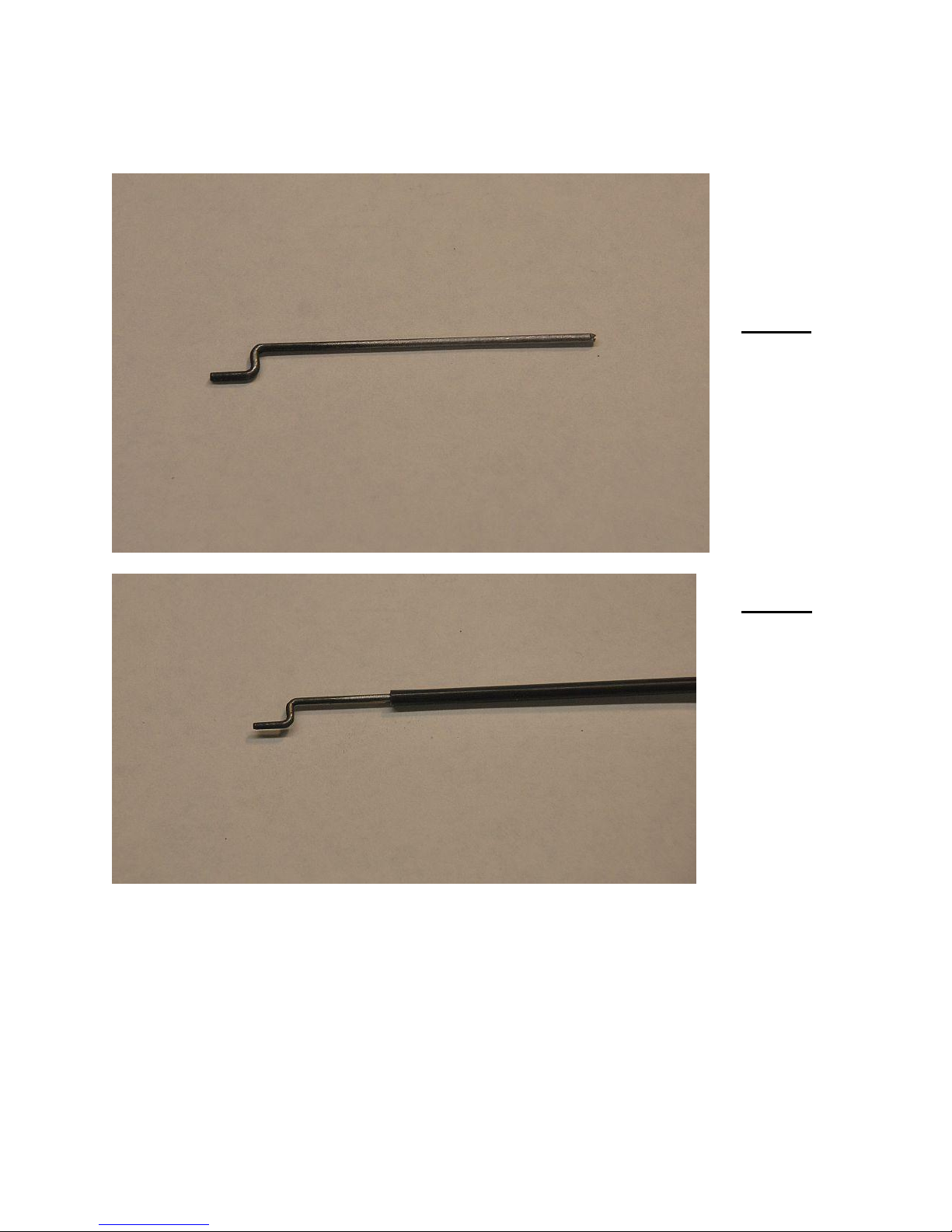
Step 29a
Cut the pushrod wire
into 3” long sections and
form a Z bend on one
end.
Step 29b
Cut a section of carbon
fiber tube to length and
insert the Z-bend wire
into one end of the tube.
(Prior to insertion, it is
best to rough sand the
end of the rods for better
adhesion.) Secure with
thin CA.
attached with Z bends. Support the Stalker elevator pushrod with the plastic support
provided.
© Copyright 2011 all rights reserved`

22
Step 29c
Heat shrink a section of
heat shrink tubing onto
the end of the carbon
fiber tube. Wick thin CA
into the joint between the
heat shrink and the tube.
Step 30
Attach the pushrod to
the control horn and
then attach a section of Z
bent wire into the servo
arm. Insert the wire into
the end of the push rod
and adjust its length so
that the control surface
is neutral when the servo
is centered. Secure in
place with thin CA. Heat
shrink a section of heat
shrink tubing onto the
end of the carbon fiber
tube.
© Copyright 2011 all rights reserved`

23
Motor, ESC, Receiver and Battery installation
Step 31
Mount the motor using #2
wood screws and
washers. Check to make
sure the motor turns
freely and there is no
interference between the
rotating motor
components and the
fuselage. Tip: Right
thrust adjustments can be
made by placing #2
washers under the left
legs of the motor mount.
Step 32
Mount the ESC and
receiver with Velcro on
the LEFT side of the
fuselage as shown.
© Copyright 2011 all rights reserved`

24
Step 33
Mount the battery with
Velcro strips on the
RIGHT side of the
fuselage as shown. A
Velcro strap can be added
for additional security.
Stalker
3” to 3¼”
Extra 300
3½” to 3¾”
Edge 540
3” to 3¼”
Lek-Trick
3¼” to 3½”
Pre-flight checklist
Balancing:
We recommend that you perform initial flights with the CG located behind the leading edge at the
wing root as shown below. Adjust the CG to get the flight characteristics that suit your taste.
© Copyright 2011 all rights reserved`

25
Electrical Components:
Check that all electrical components are securely attached and the all plugs are fully seated.
Secured any extra length on servo leads neatly within the fuselage or taped to the wing. Avoid
loose or dangling wires.
Controls:
Check that all the control surfaces move in the correct direction. For 3D flying adjust the servos and
pushrod locations to give 450 of control surface travel. If you radio has a dual rate function set the
low rates to suit your taste (We use approximately 50%). We recommend 30-40% expo to start.
Recommended throws on the Stalker are 3/8” for the elevator and 3/4” for the ailerons.
Prior to each day’s flying, always perform range check of your equipment in accordance with
the manufactures instructions.
© Copyright 2011 all rights reserved`
 Loading...