

FlatfoilZ EXTRA 300, STALKER, LEK-TRICK, EDGE 540 Assembly Manual
FlatfoilZ Assembly Guide
EXTRA 300, EDGE 540, LEK-TRICK & STALKER
Version 1.0
10-27-11

2
Limited Warranty
FlatfoilZ takes pride in the care and attention given to the manufacture of the components in this kit. The
company warrants replacement of any materials found to be defective for their intended use prior to their
use in the construction of the model, provided the purchaser requests such replacement within a one year
period from the date of purchase, and the part is returned, if so requested by the Company. No other
warranty, expressed or implied, is made by the company with respect to this kit. The purchaser assumes
full responsibility for the risk and all liability for personal or property damage or injury resulting from the
purchaser’s use of the components of this kit whether assembled or not.
The Company reserves the right to provide a full refund to the purchaser if the model does not perform as
advertised. Any refund is at the sole discretion of the Company.
Introduction:
Thank you for choosing one of the FlatfoilZ Profile Series airplanes. The assembly of all the
FlatFoilZ planes is very simple and requires a minimum of building skills. This Quick Start Guide is
provided for those with some building experience. The full Assembly Manual is available at 3DX
Hobbies.com.
Warning
This radio-controlled model is not a toy and, if operated inappropriately can cause serious
bodily injury and property damage. It is the buyer’s responsibility to assemble the kit correctly
and properly install the motor, radio and all other equipment. The model must always be flown in
accordance with the safety standards of the Academy of Model Aeronautics (AMA).
Recommended Power System:
The FlatFoilZ series of planes have been designed to use a 175 to 250 watt power system.
Recommended motors include the Hacker A20-20L, Scorpion 2215-18, or AXI 2217-16. The
prototypes were flown with a 1350 mAh, 3S Li-poly battery and a 25 amp ESC. Other power
systems with similar capabilities can be used. Performance will vary depending on the specific
power system selected. For information on alternate power systems please visit
http://3dxhobbies.com or your local hobby shop.
General Comments on Assembly:
While not difficult to assemble, the FlatFoilZ Series kits are intended for persons with some building
experience. As such, the instructions are presented as a simple sequence that, when followed, will
help ensure that the airframe turns out straight and light. Improperly aligned surfaces and
unnecessary weight will only hinder its performance. All the FlatFoilZ prototype wings and fuselages
were laminated using 15 minute epoxy thinned with alcohol. Apply glue and epoxy in a thin uniform
coat, using only enough to achieve a strong bond. Excess glue or epoxy will only add unnecessary
weight and will not increase the strength of your model. Trial fit all components to ensure fit and
alignment before applying any glue or epoxy. Keeping joints tight fitting will minimize the amount of
glue required and will ensure a strong bond. Use a light touch while sanding. Foam cuts very
quickly and excess pressure can limit your ability to accurately shape the foam. Take extra care not
to over sand. Avoid scratching the surface of the Depron foam.
© Copyright 2011 all rights reserved`
3
Fuselage Assembly:
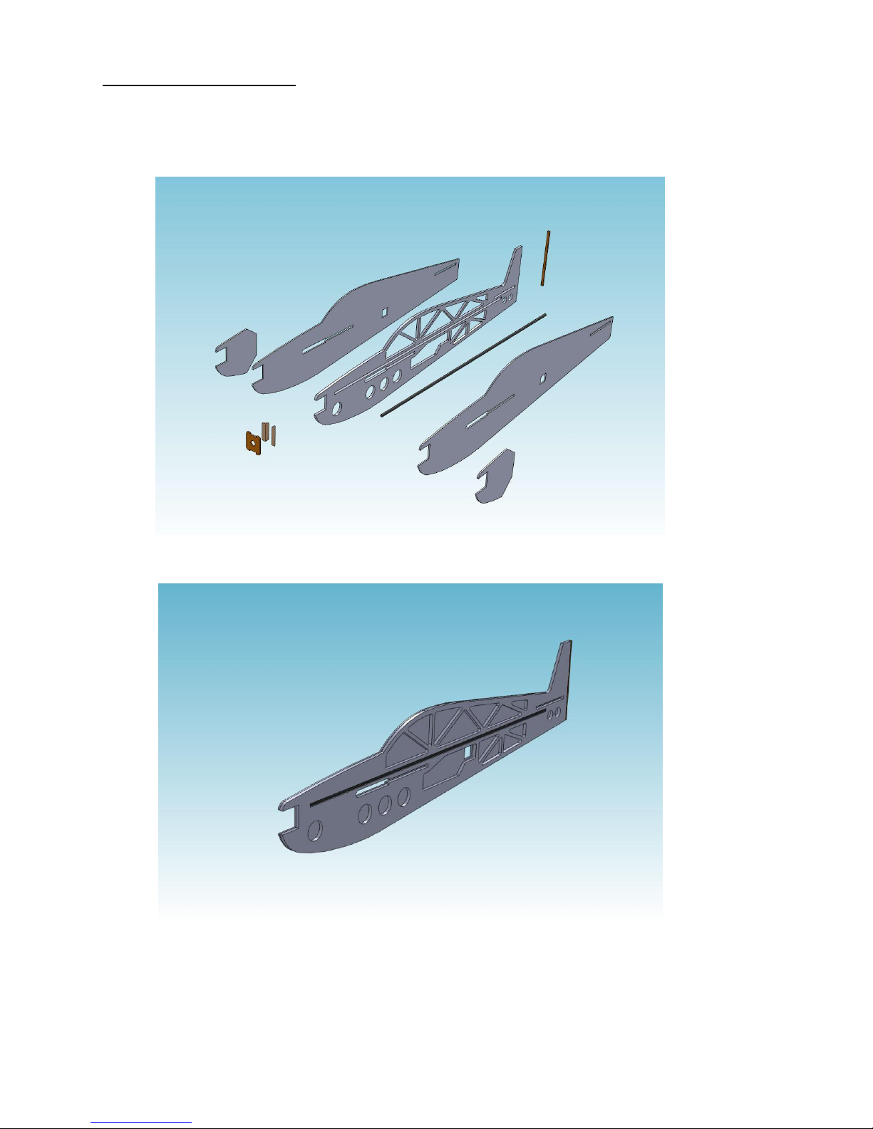
Exploded View of Typical Fuselage Assembly
Fuselage with Right Skin and Carbon Fiber Spar in Place
The fuselage assembly on the FlatfoilZ NX Profile Series kits consists of a 6 mm depron laser cut
core, over which are laminated 3 mm depron skins. A 6 mm carbon tube is embedded in the 6mm
core piece.
© Copyright 2011 all rights reserved`
4
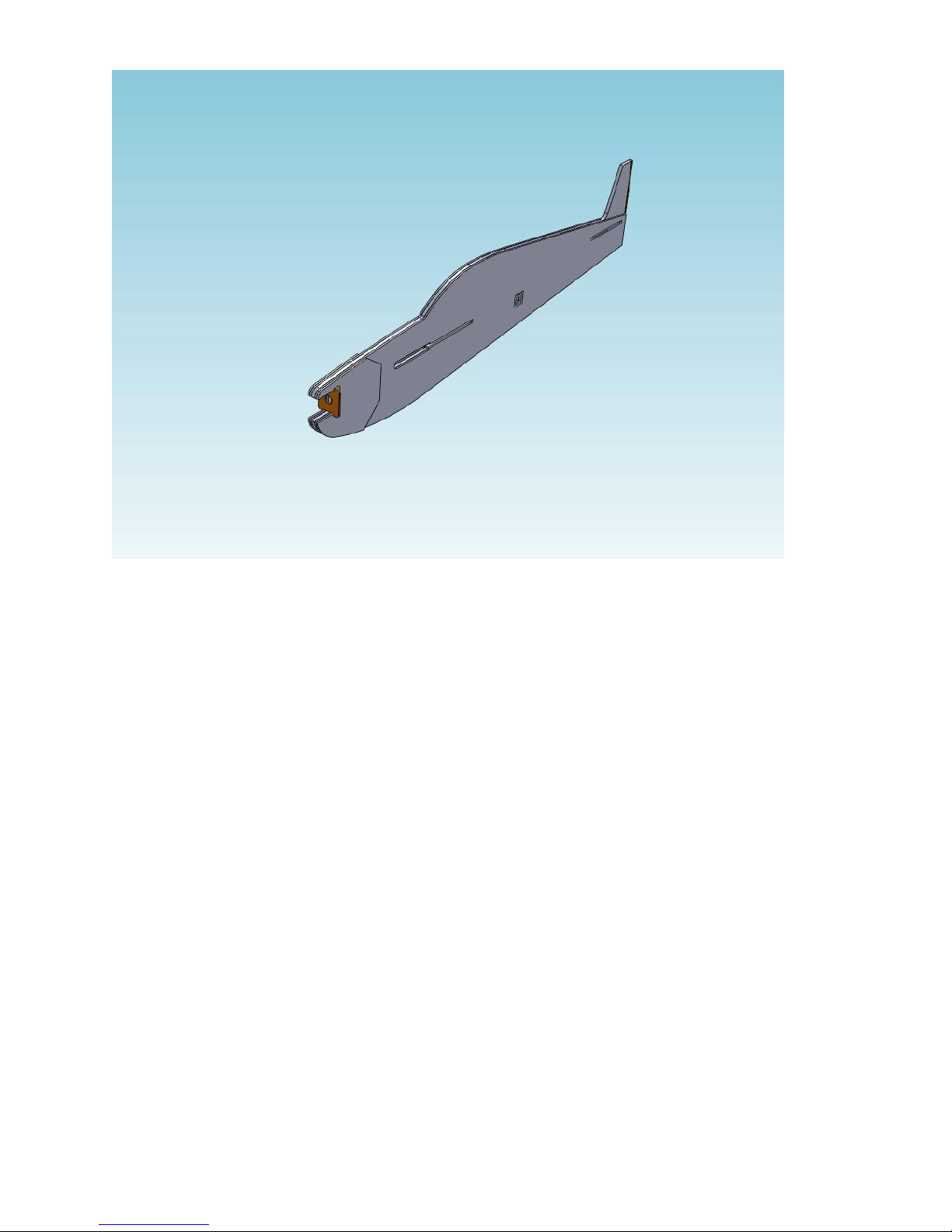
Completed Fuselage Assembly
Follow the steps in the order outlined below to ensure accurate alignment of the
components.
© Copyright 2011 all rights reserved`
5
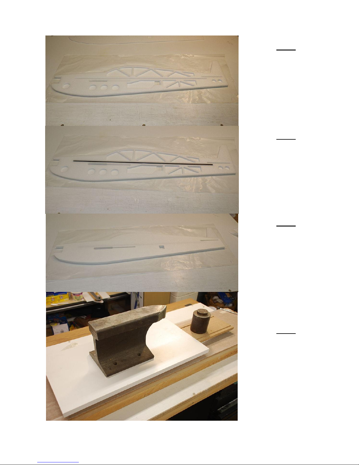
Step 1
Apply thinned 15 min
epoxy to one side of the
6mm fuselage core and
position the core on the
3mm fuselage skin .
Step 2
Apply epoxy into the
center slot in the
fuselage core and insert
the 6mm carbon tube
spar into the slot.
NOTE: Lightly sand the
surface of carbon tube
for better glue adhesion.
Step 3
Apply thinned 15 min
epoxy to the other side
of the 6mm fuselage
core and position the
other 3mm fuselage skin
over the core.
Step 4
Place the glued
assembly on a flat
building surface and
weigh down to ensure
the assembly dries flat
and true.
© Copyright 2011 all rights reserved`
6
Step 5
Glue the 3mm depron
nose doublers on both
sides of the fuselage.
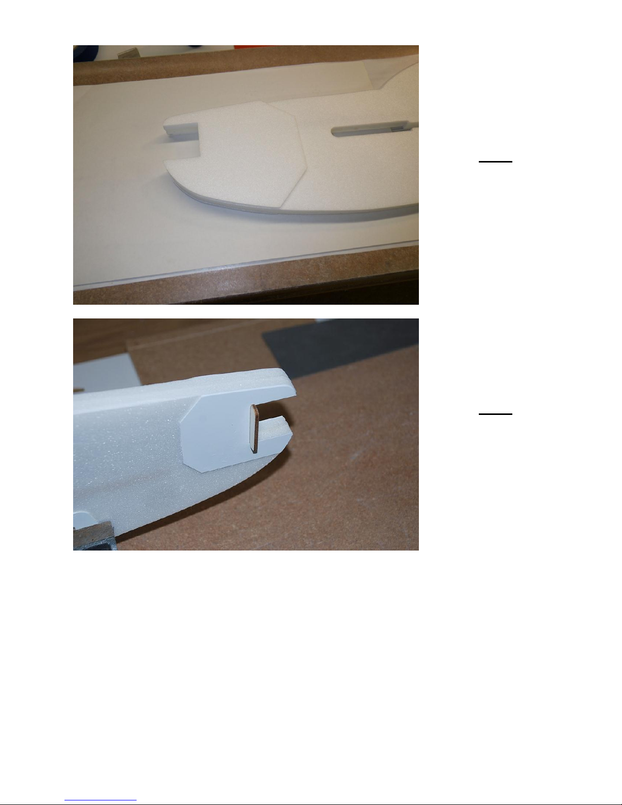
Step 6
Test fit the ply motor
mount in the fuselage
opening.
© Copyright 2011 all rights reserved`
7
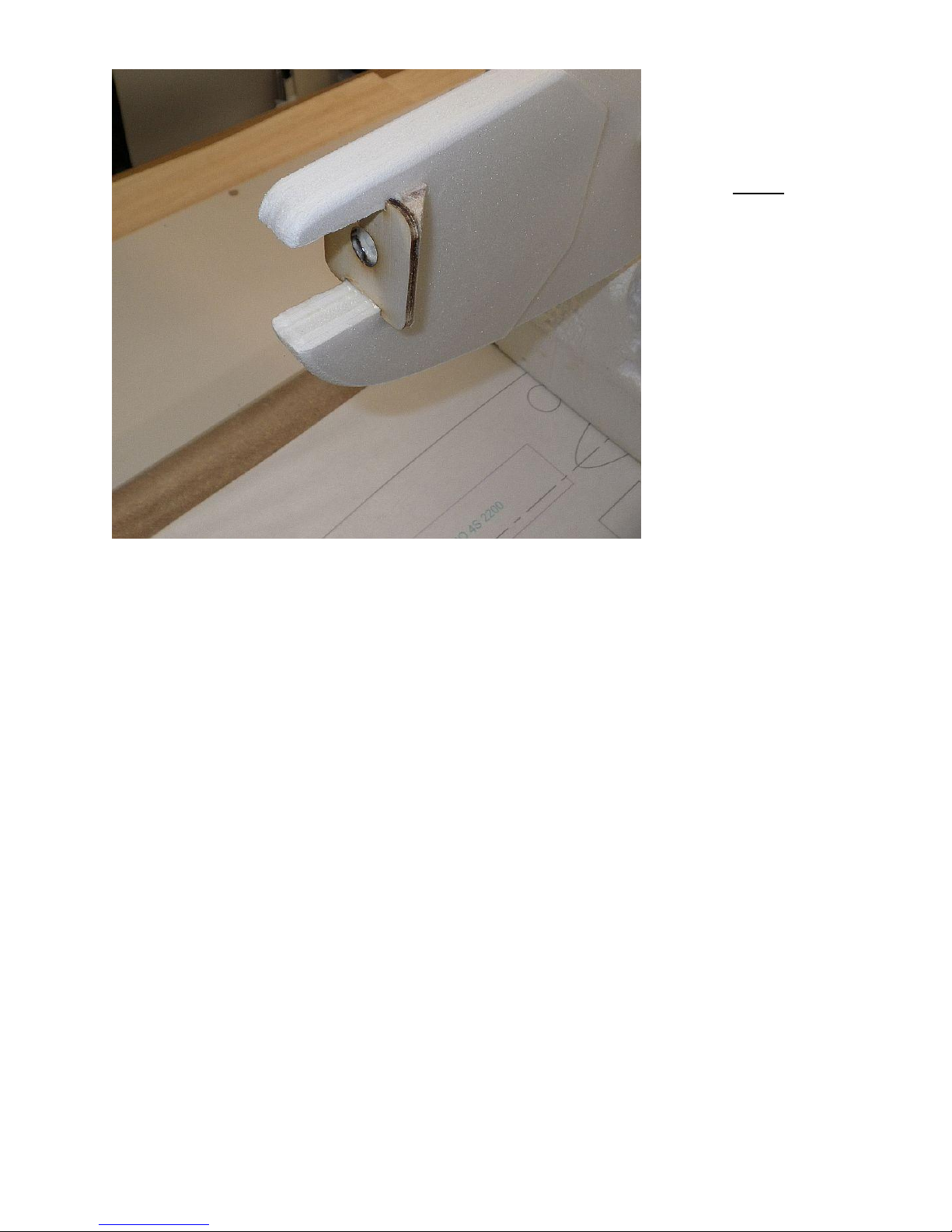
Step 7
Cut the balsa tri-stock
motor mount supports
to the proper length and
check their fit behind
the motor mount.
Epoxy the motor mount
and balsa tri-stock rear
supports in place
making sure that the
motor mount is square
to the fuselage.
If you would like to finish the edges of the fuselage, use your sanding block to smooth and
either bevel or round the edges approximately 1/8 inch. Sand the edges of the motor mount
and motor mount supports smooth using a sanding stick or emery board.
© Copyright 2011 all rights reserved`
8
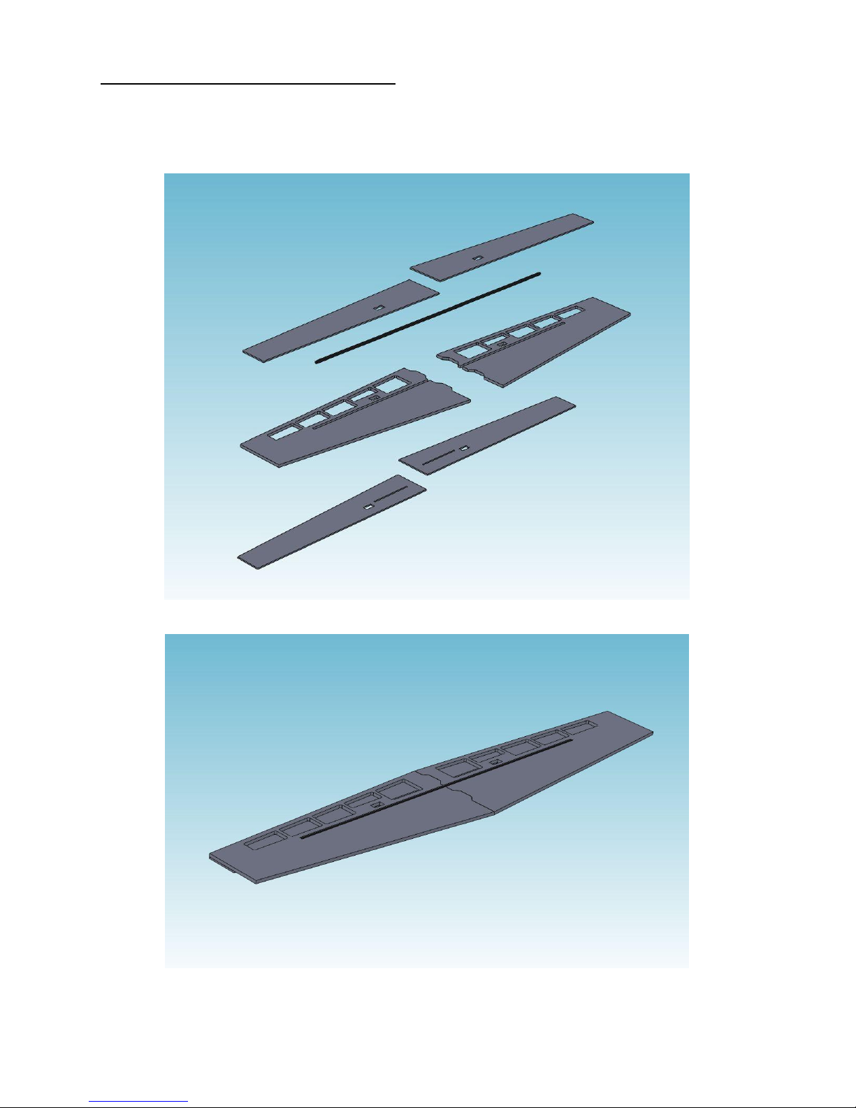
Wing Assembly and Installation
Exploded View of Typical Wing Assembly
Wing with Bottom LE Skin and Carbon Fiber Spar in Place
The fuselage assembly on the FlatfoilZ NX Profile Series kits consists of a 6 mm depron laser cut
core, over which are laminated 3 mm depron leading edge skins. A 6 mm carbon tube is embedded
in the 6mm core piece.
© Copyright 2011 all rights reserved`
 Loading...