

Flatfire Solas, SL-26N, SL-26P Installation & Operation Manual
Installation & Operation Manual
This appliance may be installed in an aftermarket, permanently located manufactured
home (USA only) or in a mobile home, where
not prohibited by local codes.
This appliance is for use only with the type of
gas indicated on the rating plate. This appliance is not convertible for use with other gases,
unless a certified conversion kit is used.
Ce manual est disponsible en Français sur demande.
Report # 361-F-01-5
INSTALLER: Leave this manual with the appliance
CONSUMER: Retain this manual for future reference
This manual specifies the installation and
operation requirements for the Flatfire Model
Nos. SL-26N, SL-26P.
WARNING: If the information in these
instructions is not followed exactly, a fire
or explosion may result causing property
damage, personal injury or loss of life.
- Do not store or use gasoline or other
flammable vapors and liquids in the
vicinity of this or any other appliance.
- WHAT TO DO IF YOU SMELL GAS
• Do not try to light any appliance.
• Do not touch any electrical switch;
do not use any phone in your
building.
• Immediately call your gas supplier
from a neighbor’s phone. Follow the
gas supplier’s instructions.
• If you cannot reach your gas
supplier, call the fire department.
- Installation and service must be
performed by a qualified installer, service
agency or the gas supplier.
AVERTISSEMENT: Assurez-vous de bien suivre
les instructions données dans cette notice pour
réduire au minimum le risque d’incindie ou
d’explosion ou pour éviter tout dommage
matériel, toute blessure ou la mort.
- Ne pas entreposer ni utilizer d’essence ni
d’autres vapeurs ou liquides inflammables dans
le voisinage de cet appareil ou de tout autre
appareil.
- QUE FAIRE SI VOUS SENTEZ UNE ODEUR DE
GAZ:
Ne pas tenter d’allumer d’appareil.
Ne touchez à aucan interrupteur. Ne pas
vous servir des téléphones se trouvant
dans le bâtiment où vous trouvez.
Appelez immédiatement votre
fournisseur de gaz depuis un voisin.
Suivezles instructions du fournisseur.
Si vous ne pouvez rejoindre le fournisseur
de gaz, appelez le service des incindie.
- L’installation et l’entretien doivent être assurés
par un installateur ou un service d’entretien
qualifié ou par le fournisseur de gaz.
Cet appareil peut être installé dans une maison
préfabriquée (mobile) déjà installée à demeure
si kes règlements locaux le permettent.
Cet appareil doit être uniquement avec las type
de gaz indiqué sur la plaque signalétique. Cet
appareil ne peut être converti à d’autres gaz,
sauf si une trousse de conversion est utilisée.
Ne pas utiliser cet appareils’il a été plongé,
meme partiellement, dans l’eau. Appeler un
technician qualifié pour inspecter l’appareail et
remplacer toute partie du système de commande
et toute commande qui a été plongée dans /’eau.
Attention. Au moment de l’entretien des commandes, étiquetez tous les fils avant de les débrancher. Des erreurs de la câblage peuvent entraîner un fonctionnement inadequate et dangereux.
S’assurer que l’appareil fonctionne adéquatement une fois l’entretien terminé.
AVERTISSEMENT. Ne pas utiliser l’appareil
si le panneau frontal en verre n’est pas en place,
est craqué ou brisé. Confiez le remplacement du
panneau à un technician agree.
INSTALLATEUR: Laissez cette notice avec l’appareil.
COMSOMMATEUR: Conservez cette notice pour consultation ultérieur.
2

TABLE OF CONTENTS
IMPORTANT SAFETY INFORMATION 4
SPECIFICATIONS 5
INSTALLATION 6
MASSACHUSETTS REQUIREMENTS 7
VENTING 8
ASSEMBLY & INSTALLATION 16
GAS CONNECTION 21 & 26
LIGHTING AND OPERATION 31
MAINTENANCE 33
REPLACEMENT PARTS LIST 34
MAINTENANCE LOG FORMS 35
CONTROL SCHEMATIC 36
INSTALLATION RECORD FORM 37
WE STRONGLY SUGGEST THAT YOU READ THIS MANUAL THOROUGHLY BEFORE BEGININNG THE INSTALLATION OF THE SOLAS DIRECT VENT GAS FIREPLACE. ALTHOUGH THE BASIC REQUIREMENTS FOR THE INSTALLATION OF ALL DIRECT VENT
GAS FIREPLACES ARE SIMILAR, EACH SPECIFIC PRODUCT HAS ITS OWN UNIQUE SETUP AND INSTALLATION REQUIREMENTS THAT MUST BE FOLLOWED EXACTLY. PLAN
YOUR INSTALLATION IN ADVANCE BY CAREFULLY REVIEWING ALL THE INFORMATION CONTAINED IN THIS MANUAL.
3

IMPORTANT SAFETY INFORMATION
The installation must conform with local codes or, in the absence of local codes, with the National Fuel
Gas Code, ANSI Z223.1 or the Canadian Installation Code, CAN/CGA B149.
A manufactured home (USA only) or mobile home OEM installation must conform with the Manufactured
Home Construction and Safety Standard, Title 24 CFR, Part 3280 or when such a standard is not applica-
ble, the Standard for Manufactured Home Installations, ANSI/BCSBCS A225.1, or Standard for Gas
Equipped Recreational Vehicles and Mobile Housing, CSA Z240.4.
The appliance and its appliance main gas valve must be disconnected from the gas supply piping system
during any pressure testing of that system at test pressures in excess of 1/2 psi (3.5 kPa).
The appliance must be isolated from the gas supply piping system by closing its equipment shutoff valve
during any pressure testing of the gas supply piping system at test pressures equal to or less than 1/2 psi (3.5
kPa).
The installation must provide for adequate ventilation air to the appliance.
This gas appliance must not be connected to a chimney flue serving a separate solid-fuel burning appliance.
The appliance, when installed, must be electrically grounded in accordance with local codes, or, in the
absence of local codes, with the National Electrical Code ANSI/NFPA 70, or the Canadian Electrical Code,
CSA C22. 1.
The appliance area must be kept clear and free from combustible materials, gasoline and other flammable
vapors and liquids.
The flow of combustion and ventilation air must not be obstructed.
Do not use this appliance if any part has been under water. Immediately call a qualifed service technician
to inspect the appliance and to replace any part of the control system and any gas control which has been
under water.
Due to high temperatures, the appliance should be located out of traffic and away from furniture and
draperies.
Children and adults should be alerted to the hazards of high surface temperatures and should stay away to
avoid burns or clothing ignition.
Young children should be carefully supervised when they are in the same room as the appliance.
Clothing or other flammable material should not be placed on or near the appliance.
Any screen or guard removed for servicing an appliance must be replaced prior to operating the appliance.
Installation and repair should be done by a qualified service person. The appliance should be inspected
before use and at least annually by a professional service person. More frequent cleaning may be required
due to excessive lint from carpeting, bedding material, etc. It is imperative that the control compartments,
burners and circulating air passageways of the appliance be kept clean.
WARNING: Do not operate the appliance with the glass door assembly removed, or if the glass is
cracked or broken. Replacement of the glass should be done by a qualified service
person.
WARNING: Use only glass assembly, P/N 26-510 which includes the glass panel, frame and gasket.
Do not use substitute materials. Do not strike or slam the glass front. Do not use
abrasive cleaners. Do not clean when hot.
4
INPUT Natural Gas Propane (LP)
Input Rating-Btu/hr 19,000 19,000
Min. Input-Btu/hr 11,000 11,000
Orifice-DMS 5/64” #55
GAS SUPPLY
Manifold Pressure 4.8”w.c. / 1.2kPa 10.0”w.c. / 2.5kPa
Min. Supply Pressure 5.5”w.c. / 1.4kPa 11.0”w.c. / 2.8kPa
Max. Supply Pressure 10.0”w.c. / 2.5kPa 13.0”w.c. / 3.3kPa
EFFICIENCY
Steady State Efficiency - % 65.0 61.4
Annual Fuel Utilization Efficiency (AFUE) - % 64.2 60.5
Canadian p.4 Efficiency - % 55.1 50.0
SPECIFICATIONS
It is recommended that the pilot flame be turned off if the appliance will not be in use for an extended
period of time.
This appliance is equipped for use with the fuel type indicated on the rating plate.
This appliance has been certified by OMNI-Test Laboratories, Inc. to ANSI Z21.88-2005 • CSA 2.33-2005
Vented Gas Fireplace Heaters and CAN/CGA-2.17-M91, Gas-Fired Appliances for Use At High Altitudes.
The is approved for installation at elevations up to 2000 feet in the U.S. and 1370 meters (4500 feet)
in Canada without change. If your installation is at an elevation greater than these, consult with the local
authority having jurisdiction for gas product installations to determine their specific requirements for high
altitude installations.
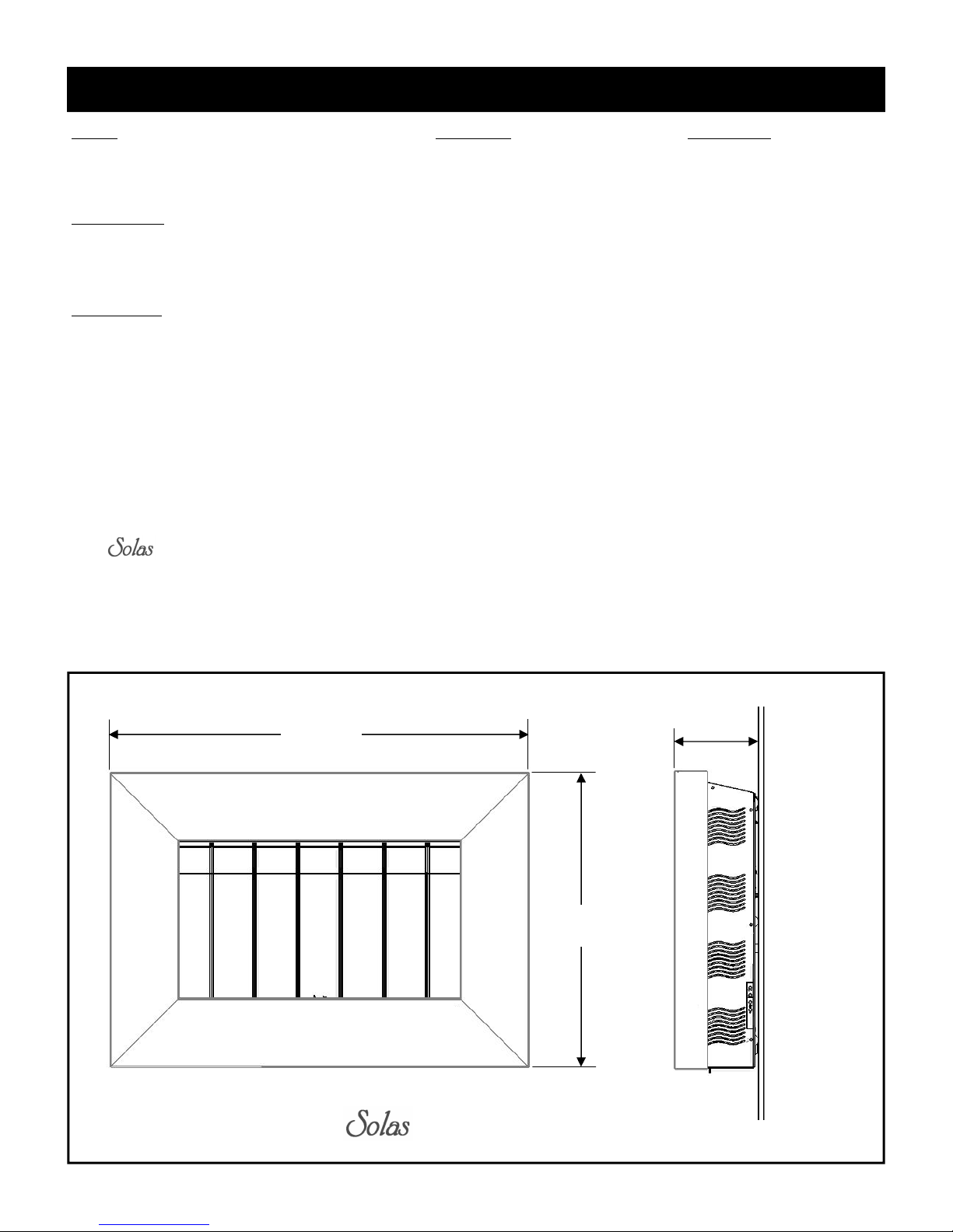
38 3/4””
(984mm)
27 1/4”
(692mm)
7 5/8””
(193mm)
OVERALL DIMENSIONS
5
INSTALLATION
Several issues must be addressed when selecting a suitable location for your fireplace. The minimum
clearances to combustible construction are listed below. In addition, access to the gas supply must be considered. The location of the fireplace will also affect the venting requirements and you must be certain the
location will allow compliance with the venting requirements shown on page 8. You must also insure that
your installation provides adequate accessibility clearance for servicing and proper operation.
Installation and repair should be done by a qualified service person. The appliance should be inspected
before use and at least annually by a professional service person. More frequent cleaning may be required
due to excessive lint from carpeting, bedding material, etc. It is imperative that the control compartment,
burners and circulating air passageways of the appliance be kept clean.
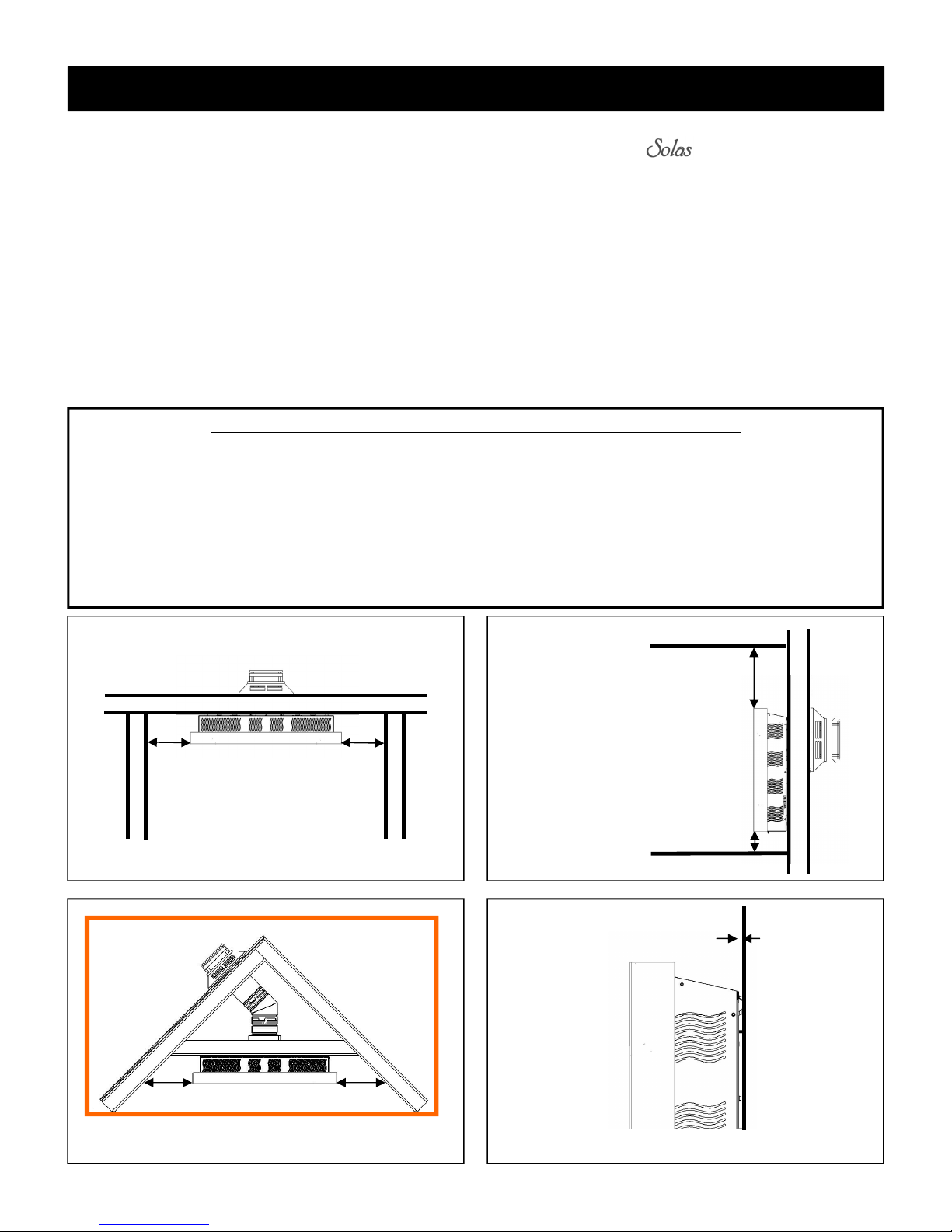
MINIMUM CLEARANCES TO COMBUSTIBLE CONSTRUCTION
Fireplace to L. Side Wall 6” (152mm) Fireplace to Ceiling 8” (203mm)
Fireplace to R. Side Wall 6” (152mm) Fireplace to Rear Wall 0” (0mm)*
Fireplace to Corner Wall 6” (152mm) Fireplace to Floor 3” (76mm)**
Vent Pipe to Adjacent Materials 1.5” (38mm)
*Mounting plate bosses contact the wall
**The minimum required clearance to be maintained from the fireplace to combustible flooring is measured from the top surface of carpeting, tile, etc.
A = 6” (152mm)
A
WALLS
B = 6” (152mm)
A
CEILING
C = 8” (203mm)
D = 3” (76mm)
FLOOR
E = 5/16” (8mm)
C
D
WALL
E
B B
CORNER
AIR SPACE BEHIND MOUNTING PLATE
6

INSTALLATION
The gas fireplace is shipped with a plugged 3/8” NPT connection. The gas supply piping should have a
separate gas shutoff valve and a 1/8” NPT plugged tapping upstream of the valve. The stove and its main
control valve must be disconnected from the gas supply piping system during any pressure testing of that
system at test pressures in excess of 1/2 psi (3.5 kPa). The stove must be isolated from the gas supply piping system by closing the main control valve during any pressure testing of the gas supply system at test
pressures equal to or less than 1/2 psi (3.5 kPa). After the gas supply has been connected, use a commercial
gas leak detector or apply a soapy water solution to all the fittings to check for gas leaks. Never use a
flame to test for leaks.
REQUIREMENTS FOR THE COMMONWEALTH OF MASSACHUSETTS
This product must be installed by a licensed plumber or gas fitter when installed within the Commonwealth of Massachusetts. If this appliance is installed in a dwelling, building or structure used in
whole or in part for residential purposes and the installation includes a horizontal vent termination
that is less than seven (7) feet above the finished grade in the area of the venting, including but not
limited to decks and porches, a hard-wired carbon monoxide detector with an alarm and battery
back-up must be installed on the floor level of the dwelling, building or structure where the appliance is to be installed.
Additionally, a hard-wired or battery operated carbon monoxide detector with an alarm must be installed on each additional level of the dwelling, building or structure served by the appliance. It shall
be the responsibility of the property owner to secure the services of qualified licensed professionals
for the installation of hard-wired carbon monoxide detectors.
In the event that the horizontally vented appliance is installed in a crawl space or attic, the hardwired carbon monoxide detector with alarm and battery back-up may be installed on the next adjacent floor level.
In the event that this requirement cannot be met at the time of completion of the installation of the
appliance, the owner shall have a period of thirty (30) days to comply with the requirement. However, during said thirty (30) day period, a battery operated carbon monoxide detector with alarm
must be installed.
Each carbon monoxide detector as required in accordance with the above provisions must comply
with NFPA 720 and be ANSI/UL 2034 and IAS certified.
In addition when the vent termination is less than seven (7) feet above finished grade a metal or plastic identification plate must be permanently mounted to the exterior of the building at a minimum
height of eight (8) feet above grade directly in line with the exhaust vent terminal. The sign shall
read, in print size no less than one-half (1/2) inch in size, “GAS VENT DIRECTLY BELOW. KEEP
CLEAR OF ALL OBSTRUCTIONS”.
A COPY OF THESE INSTRUCTIONS PLUS ALL VENTING INSTRUCTIONS WHICH INCLUDE PARTS LISTS, AND/OR ALL VENTING DESIGN INSTRUCTIONS MUST REMAIN
WITH THE STOVE AT THE COMPLETION OF THE INSTALLATION.
ATTENTION INSTALLERS: Mark below which venting system was used in the installation. These
instructions must remain with the Installation & Operation Manual.
Simpson DuraVent GS/PRO® Selkirk Direct-Temp®
AmeriVent Direct™ Metal Fab Direct Vent
Security Secure Vent™
ICC Direct Vent
7
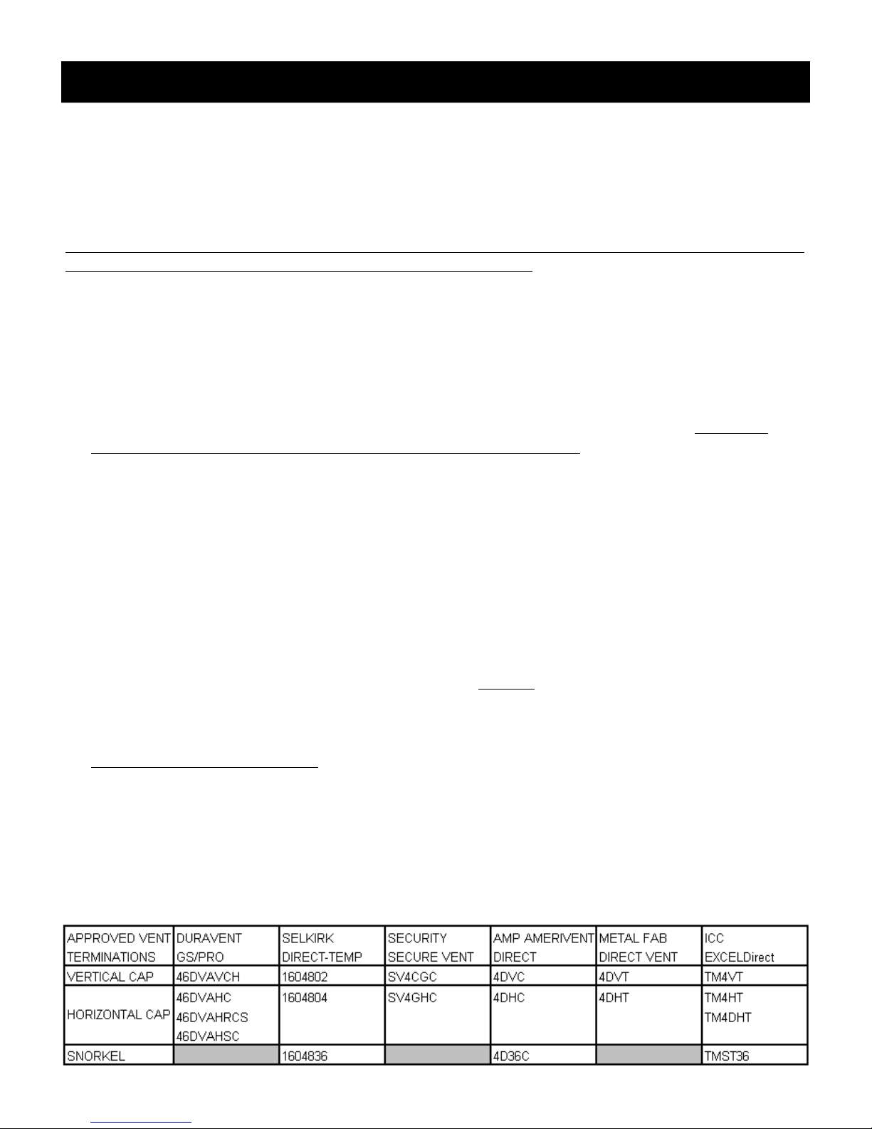
VENTING
The Solas Direct Vent Gas Fireplace has been tested and listed for installation with 4” X 6 5/8” Simpson
DuraVent GS/Pro®, Selkirk Direct-Temp
and ICC EXCELDirect venting components. Although you may the pipe components (straight pipe, elbows,
®
, Security Secure Vent™, AmeriVent Direct™, Metal Fab Direct Vent
etc.) from any of the listed manufacturers, you may only use the vent terminations (caps) listed in the chart
on page 9. For installations where a snorkel is needed, please note that only three snorkels are approved for
use. Please plan your installation accordingly.
For all specific venting installation requirements, follow the installation instructions included by the venting
manufacturer with the venting system components you have chosen.
Please note:
For venting configurations that include no vertical rise, a total horizontal vent run of up to 30 inches
(and including one 45° elbow) is allowed. However, if your installation has room to add a vertical pipe
section, we suggest adding at least one foot of vertical rise to the system.
For venting configurations that include vertical rise, it is assumed that the installation will include at
least one 90° elbow. Up to three additional 90° elbows (or equivalent 45° elbows) may also be used.
The total venting may not exceed 20 feet of vertical rise and/or 10 feet horizontal run. Refer to the
venting charts starting on page XX for specific details while you plan your installation. Note: The
number of elbows impacts the maximum allowable horizontal vent run.
Many installations will involve venting directly through standard 2 X 4 or 2 X 6 construction exterior
wall (parallel wall installation) to a horizontal vent termination (cap). The vent starter pipe has been
designed to accommodate those two common installations without the use of any additional venting
components other than a standard horizontal cap. See the chart at the bottom of this page for a list of
approved vent caps.
A special corner installation kit (Part Number CK-26-1) is also available that will allow the Solas fire-
place to be mounted in a corner without constructing a 45° partition wall. This kit is available from
your Solas dealer and has its own installation instructions. Please refer to those instructions for specific
details regarding the installation using the kit.
If the fireplace will be installed on an interior wall or other location that precludes venting directly
through an outside wall to a horizontal vent cap, or if the distance to the outside wall exceeds 30”, one
or more elbows will be required to allow addition of the required vertical venting to the installation.
When vertical venting is required, the fireplace venting may be terminated with either a vertical or horizontal vent cap depending on the specifics of the installation. Refer to the venting charts starting on
page XX for specific venting requirements and see the chart on page YY for a list of approved vent caps
before you plan your installation.
A minimum clear space of 1 1/2” must be maintained around the vent pipe where it penetrates the wall
adjacent to the fireplace (either the outside wall for the direct-through-the-wall installation or the partition wall for the 45° or other interior wall installations). A minimum clear space of 1 1/2” must also be
maintained where the vent pipe penetrates any other interior wall, exterior wall, ceiling or roof.
The location of the vent termination must meet the requirements of the current edition of ANSI Z223.1/
NFPA 54, National Fuel Gas Code or CAN B419.1, Natural Gas and Propane Installation Code and the
requirements shown on page ZZ of this manual.
8

USING THE VENTING CHARTS
The venting charts on pages 10 and 11 provide an easy means for determining whether your specific installation requires inlet air or exhaust restrictors or both. To make the determination about whether air or exhaust restrictors are needed, a venting chart worksheet is provided on page 12. Follow the instructions and
fill in the worksheet for your particular installation. This will allow you to determine the recommended
restrictor setting for you exact installation. This might appear to be a complicated process but it is really
quite straight-forward. Several examples are shown on page 13 to help guide you.
Please be sure to note that:
1. There are separate venting charts for Natural Gas and LP Gas. Refer to the appropriate chart for your
fuel type to determine your specific restrictor requirements. The settings in the charts have been determined based on extensive testing.
2. Determine the total vertical vent rise and total horizontal vent run for your installation. All measurements are made from the center of the vent opening in the back of the fireplace.
3. If your fireplace will not be venting directly though an outside wall to a horizontal termination or if
more than 30” of horizontal vent run is required, some vertical vent rise will be required for the fireplace to function and vent properly. Elbows will also be required for those installations. However, installations are limited to a maximum of four 90° elbows (or 45° elbow equivalents).
4. Note: Two 45° elbows equal one 90° elbow.
5. The recommended restrictor settings in the venting charts allow up to two 90° elbows (or 45° elbow
equivalents) to be used without affecting the restrictor settings. Additional elbows will require that you
calculate a new equivalent horizontal run for your installation to account for the additional flow resistance caused by the extra elbows. For the purposes of calculating the equivalent horizontal vent run,
each additional 90° elbow is equivalent to three feet of horizontal vent run. The total horizontal vent
run including elbow equivalents can not exceed 10 feet.
6. The maximum vertical vent rise can not exceed 20 feet.
7. There are two exhaust restrictors that are provided with your Solas fireplace. They are labeled “A” and
“B”. The A restrictor provides less exhaust restriction than B.
8. An air restrictor plate is also provided with your fireplace. It is a ring with bendable tabs that can be
set to adjust the amount of restriction in the air supply system.
PLEASE NOTE: If your specific venting configuration falls in a box in the venting charts (on pages 10 &
11) that is above the dotted line ( ), you must use one of the approved direct vent venting systems
that utilizes a stainless steel inner liner. The dotted line corresponds to a total vent length of 20 feet including vertical rise and horizontal run. This requirement is part of the ANSI standards and is based on testing
conducted to determine where the exhaust gas temperature drops to the point where condensation might occur in the vent pipe. The standards require the use of corrosion resistant liner materials if that specific total
vent length is exceeded.
9
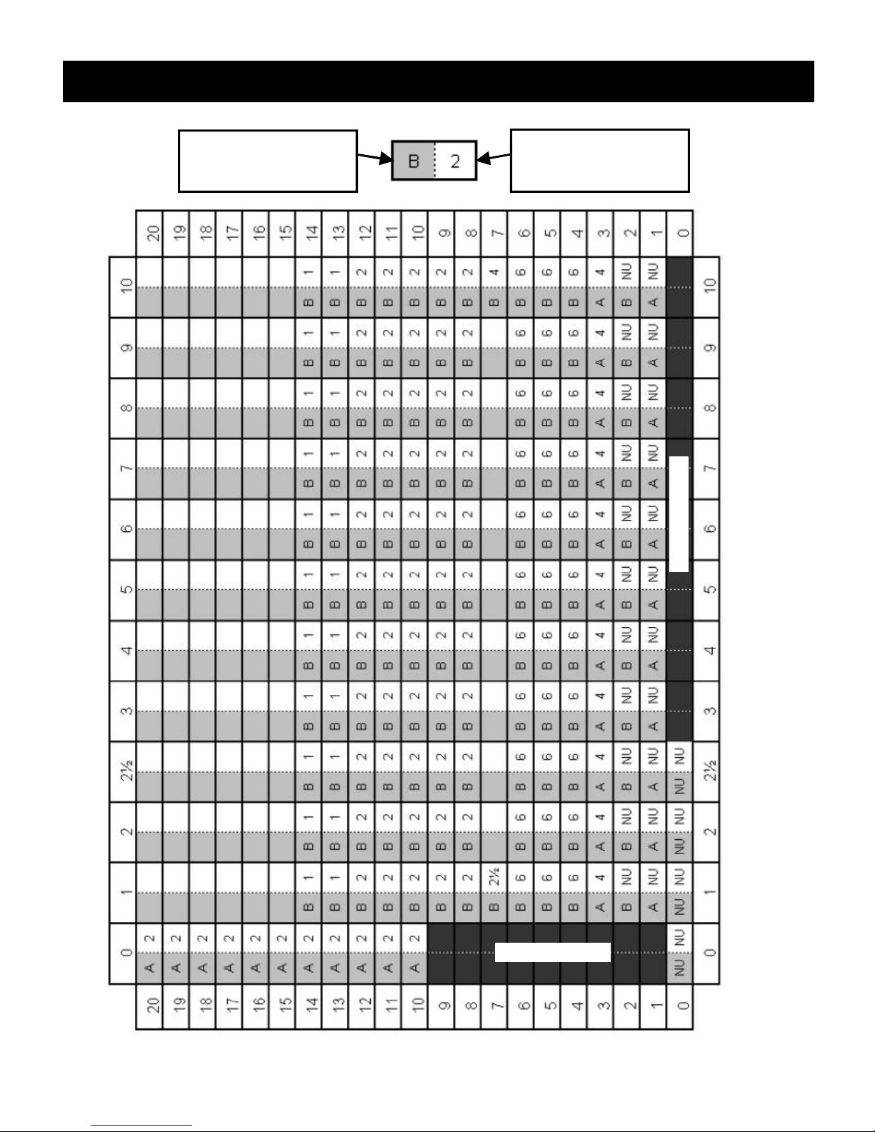
NATURAL GAS VENTING CHART
KEY
EXHAUST RESTRICTOR
A or B
NU = NOT USED
AIR RESTRICTOR
1— 6 TABS OPEN
NU = NOT USED
NOT ALLOWED
NOT ALLOWED
HORIZONTAL RUN IN FEET
VERTICAL RISE IN FEET
10

LP GAS VENTING CHART
KEY
EXHAUST RESTRICTOR
A or B
NU = NOT USED
AIR RESTRICTOR
1— 6 TABS OPEN
NU = NOT USED
NOT ALLOWED
NOT ALLOWED
HORIZONTAL RUN (FEET)
VERTICAL RISE (FEET)
11
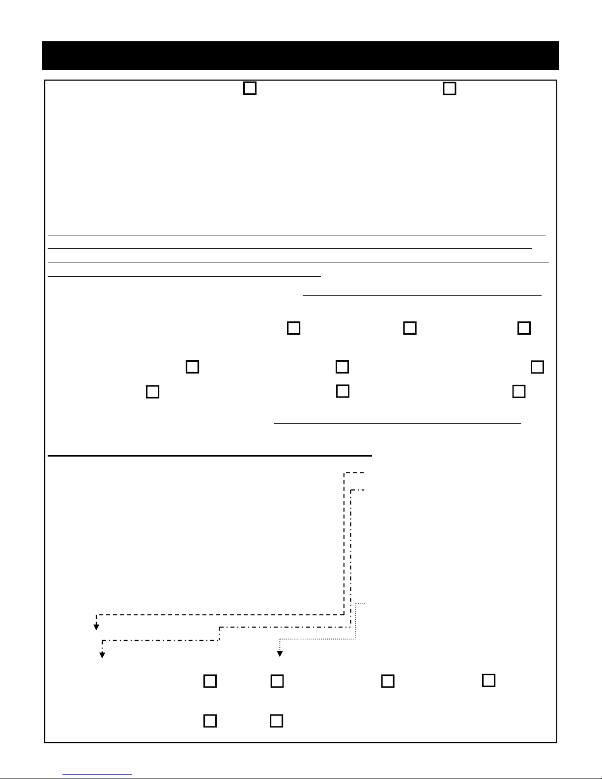
VENTING CHART WORKSHEET
A. FUEL TYPE: NATURAL GAS
LP GAS (PROPANE)
B. TOTAL VERTICAL VENT RISE (MEASURED FROM HORIZONTAL CENTERLINE OF VENT
OPENING ON THE BACK OF THE FIREPLACE TO THE HORIZONTAL CENTERLINE OF THE
VENT CAP (FOR HORIZONTAL VENT CAPS) OR TO THE FLANGE ON THE CAP (FOR VERTICAL CAPS)): _____________ FEET
C. TOTAL HORIZONTAL VENT RUN (MEASURED FROM THE VERTICAL CENTERLINE OF
THE VENT OPENING ON THE BACK OF THE FIREPLACE TO THE FLANGE ON THE CAP (FOR
HORIZONTAL CAPS) OR TO THE VERTICAL CENTERLINE OF THE CAP (FOR VERTICAL
CAPS)): _____________ FEET
NOTE: THE VERTICAL VENT RISE AND HORIZONTAL VENT RUN ARE THE OFFSETS IN THE LOCATIONS OF VENT CAP RELATIVE TO THE VENT OPENING ON THE FIREPLACE. VENT PIPE
THAT RUNS AT 45° HAS BOTH A VERTICAL RISE AND HORIZONTAL RUN. SNORKEL CAPS HAVE
BUILT-IN VERTICAL RISE THAT MUST BE COUNTED.
D. TOTAL NUMBER OF 90° ELBOWS: _______ NOTE: SNORKELS COUNT AS 2- 90° ELBOWS
E. TOTAL NUMBER OF 45° ELBOWS: _______
TERMINATION (CAP) TYPE: HORIZONTAL VERTICAL
SNORKEL
VENT BRAND:
Simpson DuraVent GS/Pro® Selkirk Direct-Temp
®
Security Secure Vent™
AmeriVent Direct™ Metal Fab Direct Vent
ICC EXCELDirect
VENT CAP MODEL NO: _______________ NOTE: SEE APPROVED VENT CAPS ON PAGE 8
EXHAUST AND AIR INLET RESTRICTORS CALCULATOR
A. Fuel Type ________
B. Total Vertical Vent Rise: ________ feet
C. Total Horizontal Vent Run (Actual): ________ feet
D. 90° Elbows Needed: ________
E. 45° Elbows Needed: ________
F. Total 90° Elbows Equivalent: D +(E x ½) = ________
G. 90° Elbows in Excess of 2: F - 2 = ________
H. Additional Horiz. Feet Equivalent: G x 3 = ________ feet
I. Horizontal Vent Run (Equivalent): C + H = ________ feet
Find _____ Chart Settings for:
B._________ feet Vertical Rise and I.__________ feet Horizontal Run (Equivalent).
Exhaust Restrictor Required: N Y IF YES: A or B
Air Restrictor Required: N Y IF YES: Number of Tabs Open: _______
12
 Loading...