

Flashtech FT-RGB-RF-Controller Installation Manual
NAME: Flashtech Wireless (RF) RGB Controller Installation Guide
MODEL: FT-RGB-RF-Controller
Summarization
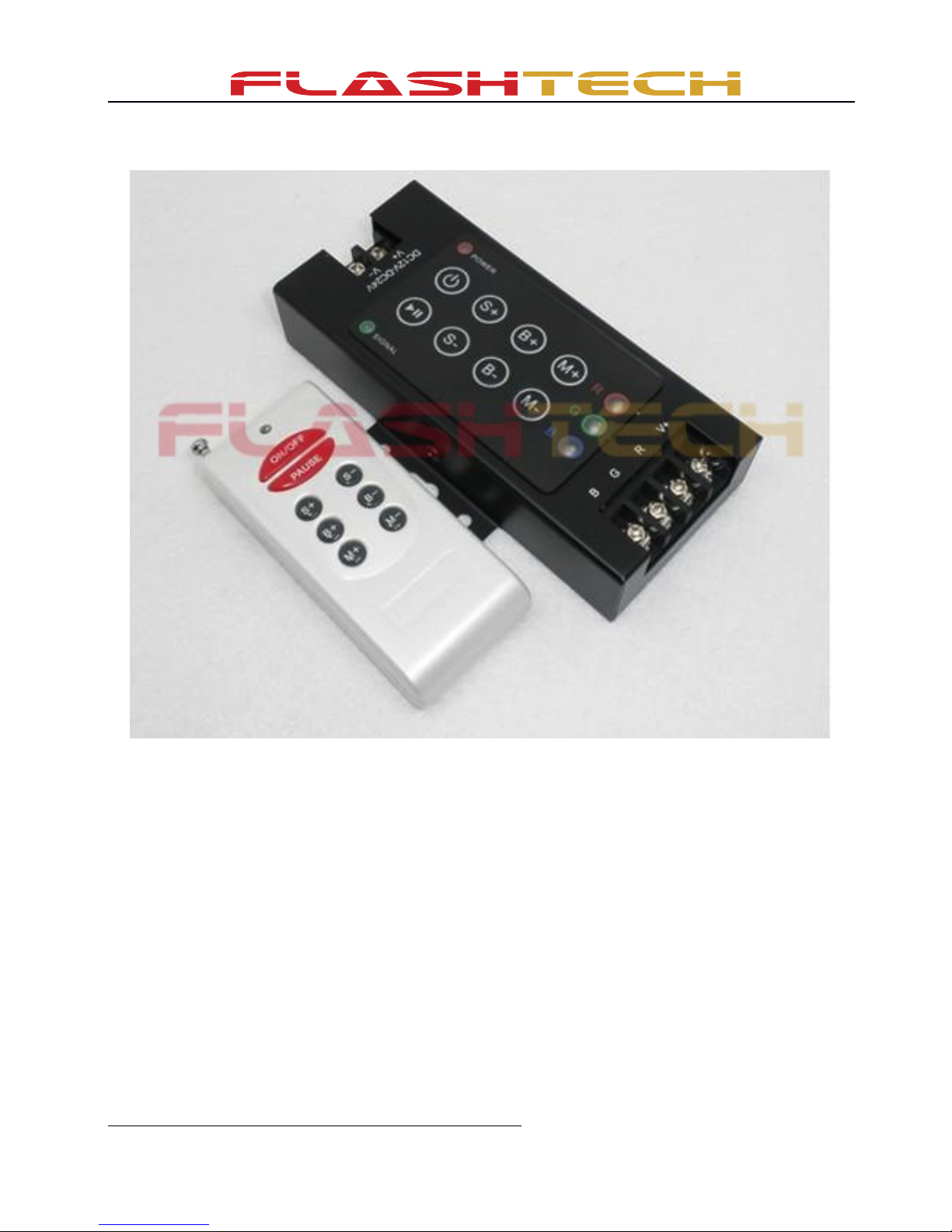
Flashtech Wireless (RF) RGB Controller is a versatile unit that is used for controlling a variety of LED Light
sources. It can be used with Flashtech: RGB Halos, RGB Flexible light strips, and RGB under Glow Light
kits. All options can be controlled via the wireless (RF) remote or from the actual control module itself. In
addition the control module has three led’s that light up and or flash depending on exactly what mode has
been selected. This allows the user to be able to mount the controller inside the vehicle and see what options
are being selected without having to view the actual light source!
Technical Parameters
● Working temperature: -4 - 140 F
● Supply voltage: DC12V
● Output: 3 channels
● Connecting mode: common anode
● External dimension: L121ΧW53ΧH25 mm
● Packing size: L150ΧW76ΧH51 mm
● Net weight: 9oz
● Gross weight: 10oz
● Static power consumption: <1W
● Output current: <4A(each channel)
● Output power: 12V:<144W,
Page 1 of 3
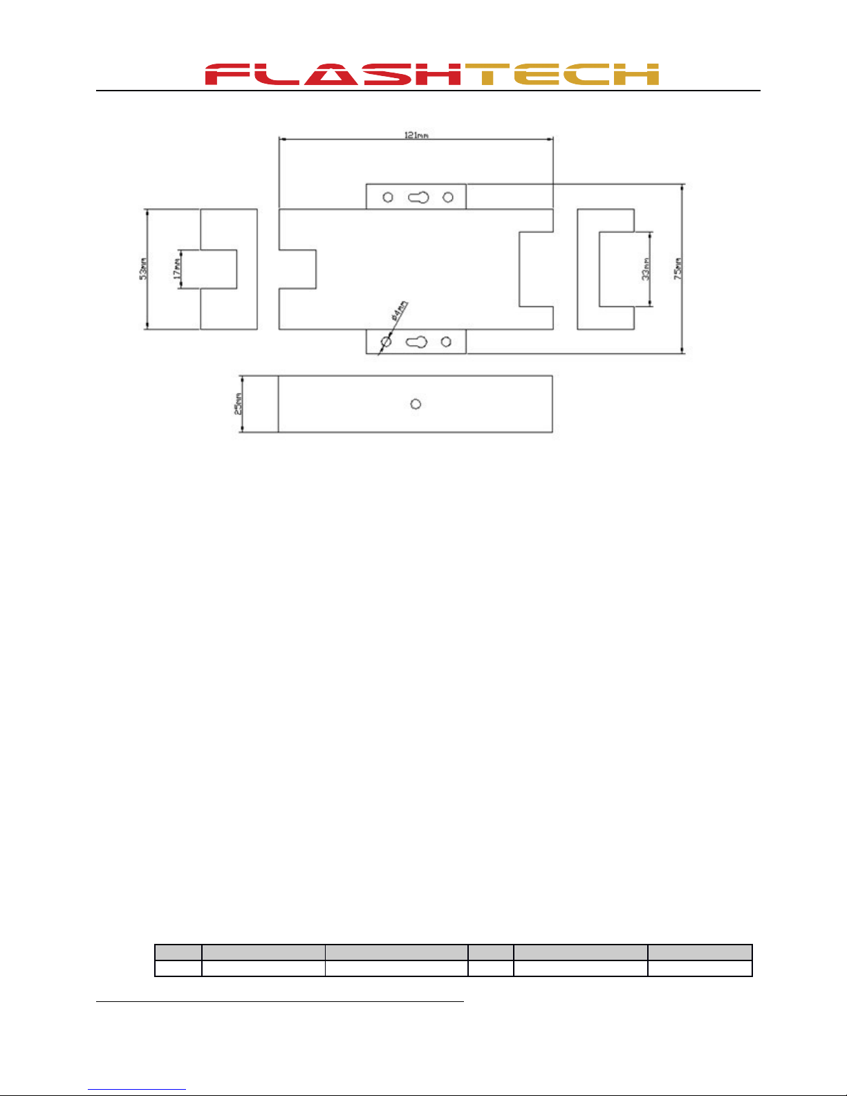
External Dimension
Interface Specifications
Power input interface:
Positive and negative wires are connected directly to a 12v DC power source. In most cases this would be
your vehicle battery. If this item is being used for home or commercial use it first must be connected to a 12v
dc power inverter.
Load output interface:
Connect each color wire directly to the appropriate screw,
BLACK wire→V + RED wire→R GREEN wire→G BLUE wire→B
• WARNING : If using this controller with Flashtech Halos, the green and blue wires may have to
be switched for proper utilization. If the controller does not function properly with the Green
wire attached to “G” and the Blue wire attached to “B”, switch them (Green wire → B ; Blue
Wire → B).
Direction for use
1. Connect the load wire first, following by the power wire; Please ensure short circuit cannot
occur between connecting wire before you turn on the power;
2. Below is the function of each button. The function of each key is as follows:
(1): you can turn on/off controller at any time
(2): Play/pause button, it is used to see the static effect of a led mode.
S(3)+: Changes the speed higher of a particular mode. One degree for every time you press
S-(4): Changes the speed lower of a particular mode. One degree for every time you press
B+(5): Changes the Brightness higher. One degree for every time you press
B-(6): Changes the Brightness lower. One degree for every time you press
M+(7): Changes the pattern forward (form below shows each option)
M-(8): Changes the pattern backwards (form below shows each option)
3. All 25 option on the controller are listed below
No. Patterns Remarks No. Patterns Remarks
1 Static red 14 Blue flash
Page 2 of 3
 Loading...