

Flash professional LED PAR 64 SLIM 7x10W RGBW Mk2 P7100408, LED PAR 64 SLIM 7x10W RGBW Mk2 P7100418 User Manual
USER MANUAL / INSTRUKCJA OBSŁUGI
LED PAR 64 SLIM
7x10W RGBW Mk2
P7100408 / P7100418

LED PAR 64 SLIM 7x10W RGBW Mk2 P7100408 / P7100418
www.flash-butrym.pl
1
Table of contents
1 Introduction ...................................................................................................................................................... 2
2 Safety information ........................................................................................................................................... 2
3 Product information ........................................................................................................................................ 2
3.1 Features ....................................................................................................................................................... 2
3.2 Specification ................................................................................................................................................ 2
4 Installation ........................................................................................................................................................ 3
5 Connections ...................................................................................................................................................... 3
5.1 Connecting DMX signal............................................................................................................................. 3
5.2 Voltage specification .................................................................................................................................. 4
5.3 Connecting power supply ........................................................................................................................ 4
6 Operation manual ............................................................................................................................................ 4
6.1 Control panel .............................................................................................................................................. 4
6.2 Master / slave .............................................................................................................................................. 4
6.3 DMX channel list ........................................................................................................................................ 5
Spis treści
1 Wprowadzenie ................................................................................................................................................. 9
2 Zasady bezpieczeństwa .................................................................................................................................. 9
3 Informacje o produkcie ................................................................................................................................... 9
3.1 Funkcje ......................................................................................................................................................... 9
3.2 Specyfikacja ................................................................................................................................................. 9
4 Instalacja ......................................................................................................................................................... 10
5 Połączenia ....................................................................................................................................................... 10
5.1 Podłączenie sygnału DMX ...................................................................................................................... 11
5.2 Specyfikacja zasilania ............................................................................................................................... 11
5.3 Podłączanie zasilania ............................................................................................................................... 11
6 Instrukcja użytkowania ................................................................................................................................. 11
6.1 Panel sterowania ...................................................................................................................................... 11
6.2 Master / slave ............................................................................................................................................ 11
6.3 Lista kanałów DMX.................................................................................................................................. 12

www.flash-butrym.pl
2
1 INTRODUCTION
Thank you for purchasing LED PAR 64 SLIM 7x10W RGBW Mk2. For safety reasons and to ensure the
trouble-free operation, carefully read the instructions.
2 SAFETY INFORMATION
1. Installation should be done by qualified personnel in order to minimize the risk of accidental
electric shock
2. Disconnect the power supply before installation.
3. Before connecting the unit to the mains, make sure it is not damaged mechanically. If you
notice any signs of damage you should contact your dealer immediately. Do not connect the
device to the mains.
4. Do not use the device in high humidity conditions and at temperatures above 40° C
5. The device must be installed on stable structures
6. Always use steel security cable to attach the device to a stable structure
7. Do not connect power supply to more than 12 devices in series.
3 PRODUCT INFORMATION
The device is equipped with high-quality, bright LEDs, while maintaining a small electric power
consumption, low operating temperature and long life. Unique design, high quality and high durability
make this device a great tool for both power users and those, who value simplicity and reliability.
The ergonomic handles (included) facilitates the use of the device in any condition. In order to expand the
range of mounting options, the holder has an additional mounting holes.
The electronics is made of high quality components and offers several features such as:
3.1 Features
16-bit dimming resolution
Various dimming curves for smooth dimming in 8-bit mode
Dim delay (light bulb simulation)
Full DMX signal regeneration
Electronic protection against overheating
THEATRE or DISCO cooling volume modes.
Permanent color correction
Native support for optional wireless DMX module
3.2 Specification
Power supply voltage: 100 - 245V
Voltage frequency: 50/60Hz
Diode type: 4in1
Number of diodes: 7
Diode power: 10W
Beam angle: 25° [P7100408] / 15° [P7100418]
Display: Color LCD 1,8”
Color: RGBW
Dimming: Linear: 0 - 100%
Number of DMX channels: 3 / 4 / 6 / 6 / 6 / 7 / 8 / 8 / 8
LED PAR 64 SLIM 7x10W RGBW Mk2 P7100408 / P7100418
www.flash-butrym.pl
3
DMX standard: DMX 512
Control interface: 4 buttons
Operating modes: DMX512, Auto, Sound-controlled, Manual color, Master
Features: 16-bit dimming, DMX Signal regeneration, Electronic protection against overheating
AC IN: powerCON
AC OUT: powerCON
DMX IN: XLR - 3 pin
DMX OUT: XLR - 3 pin
IP Rating: IP20
Housing made: ABS
Cooling: Active, temperature-controlled
Height [cm]: 27
Width [cm]: 26
Depth [cm]: 11
Weight [kg]: 1,3
4 INSTALLATION
After removing the packaging, check if the device was not damaged during transport. Before connecting to
the mains, make sure that the device is securely mounted. The manufacturer is not responsible for damage
caused by unstable mounting.
CAUTION! Always use steel security cable to attach the device to a stable structure.
Ensure proper connection to the mains and proper grounding. Make sure that the electrical parameters are
consistent with device requirements. All activities, including connecting the device to the mains must be
performed by qualified personnel.
5 CONNECTIONS
The device is equipped with the following interfaces:
1. DMX (in/out): XLR 3-pin socket
2. Power (in/out): powerCON socket
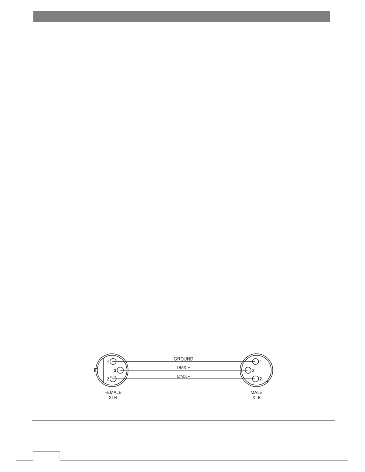
5.1 Connecting DMX signal
The connection is performed using cable with XLR-female -> XLR-Male plugs.
www.flash-butrym.pl
4
5.2 Voltage specification
Input Voltage
Total Power
Frequency
100~245V
70W
50/60Hz
5.3 Connecting power supply
The connection is performed using power cable with PowerCon connector (included).
The device must be operated by qualified personnel. Make sure that the power grid supply parameters are
consistent with device parameters and limitations are not exceeded.
CAUTION! In the case of cable damage do not attempt to repair. Replacement or repair can be made only
on the manufacturer or by a person with appropriate permissions.
Maximum number of devices connected in series: 12
6 OPERATION MANUAL
6.1 Control panel
The control panel is equipped with LCD display and 4 control buttons with the following functions:
1. ESC – go back from the selected options, go to upper menu, cancel changes
2. DOWN – choose option, edit parameter
3. UP – choose option, edit parameter
4. ENTER edit selected option, confirm changes
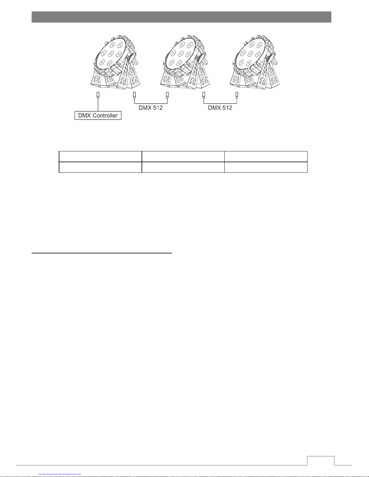
6.2 Master / slave
To achieve desired effects with Master/slave mode set the first device in DMX chain as Master (MASTER
function is [ON] ). Set the following devices to DMX mode -> Classic 8 -> CH 001
 Loading...