

Flash professional F7100079 User Manual
USER MANUAL / INSTRUKCJA OBSŁUGI
LED Moving Head
120W SPOT MK2
F7100079

LED Moving Head 120W SPOT MK2 F7100079
www.flash-butrym.pl
1
Table of Contents
1 Introduction ...................................................................................................................................................... 2
2 Safety information ........................................................................................................................................... 2
2.1 General information ................................................................................................................................... 2
2.2 AC Power .................................................................................................................................................... 2
3 Specification ..................................................................................................................................................... 3
4 Installation ........................................................................................................................................................ 3
5 Connections ...................................................................................................................................................... 4
5.1 Connecting DMX signal............................................................................................................................. 4
5.2 Fixture linking ............................................................................................................................................ 4
5.3 Master/Slave fixture linking ...................................................................................................................... 5
5.4 Voltage specification .................................................................................................................................. 5
5.5 Connecting power supply ......................................................................................................................... 5
6 Menu ................................................................................................................................................................. 6
7 DMX channel list.............................................................................................................................................. 7
Spis Treści
1 Wprowadzenie ................................................................................................................................................. 8
2 Bezpieczeństwo ................................................................................................................................................ 8
2.1 Informacje o bezpieczeństwie ................................................................................................................... 8
2.2 Zasilanie ...................................................................................................................................................... 9
3 Specyfikacja ...................................................................................................................................................... 9
4 Instalacja ......................................................................................................................................................... 10
5 Połączenia ....................................................................................................................................................... 10
5.1 Podłączanie sygnału DMX ...................................................................................................................... 10
5.2 Łączenie urządzeń szeregowo ................................................................................................................ 10
5.3 Łączenie urządzeń w układzie Master/Slave ........................................................................................ 11
5.4 Specyfikacja zasilania ............................................................................................................................... 11
5.5 Podłączanie zasilania ............................................................................................................................... 11
6 Menu ............................................................................................................................................................... 12
7 Lista kanałów DMX ....................................................................................................................................... 13

www.flash-butrym.pl
2
1 INTRODUCTION
Thank you for purchasing LED Moving Head 120W SPOT MK2. For safety reasons and to ensure the troublefree operation, carefully read the instructions.
2 SAFETY INFORMATION
2.1 General information
1. Installation should be done by qualified personnel in order to minimize the risk of accidental
electric shock.
2. Disconnect the power supply before installation.
3. Before connecting the unit to the mains, make sure it is not damaged mechanically. If you
notice any signs of damage you should contact your dealer immediately. Do not connect the
device to the mains.
4. Do not use the device in high humidity conditions and at temperatures above 40° C
5. The device must be installed on stable structures.
6. Please keep this user guide for future consultation. If you sell the unit to another user, be
sure that they also receive this instruction booklet.
7. Always make sure that you are connecting to the proper voltage, and that the line voltage
you are connecting to is not higher than that stated on the decal or rear panel of the fixture.
8. This product is intended for indoor use only!
9. To prevent risk of fire or shock, do not expose fixture to rain or moisture. Make sure that
there are no flammable materials close to the unit while operating.
10. The unit must be installed in a location with adequate ventilation, at least 20in (50cm) from
adjacent surfaces. Be sure that no ventilation slots are blocked.
11. Always disconnect from power source before servicing or replacing fuse and be sure to
replace with same fuse size and type.
12. Secure fixture to fastening device using a safety chain.
13. Never carry the fixture solely by its head. Use its carrying handles.
14. In case of a serious operating problem, stop using the unit immediately. Never try to repair
the unit by yourself.
15. Repairs carried out by unskilled people can lead to damage or malfunction. Please contact
the nearest authorized technical assistance center. Always use the same type spare parts.
16. Don't connect the device to a dimmer pack.
17. Make sure the power cord never crimped or damaged.
18. Never disconnect the power cord by pulling or gagging on the cord.
19. Avoid direct eye exposure to the light source while it is on.
2.2 AC Power
To determine the power requirements for a particular fixture, see the label affixed to the back plate of the
fixture or referred to the fixtures specification chart. A fixture listed current rating is its average current draw
under normal conditions. All fixtures must be directly powered off switched circuit and cannot be run off a
rheostat (variable resist) or dimmer circuit, even if the rheostat or dimmer source voltage matches the
fixtures requirement. Check the fixture or device carefully to make sure that if a voltage selection switch
exits that it is set to the correct line voltage you will use.

LED Moving Head 120W SPOT MK2 F7100079
www.flash-butrym.pl
3
WARNING! Verify that the voltage select switch on your unit matches the line voltage applied. Damage to
your fixture may result if the line voltage applied does not match the voltage indicated on the voltage
selector switch. All fixtures must be connected to circuits with a suitable Earth ground.
3 SPECIFICATION
Power consumption: 240W
Power supply voltage: 90 - 260V
Voltage frequency: 50/60Hz
Fuse: F7AL
Diode type: Standard LED (Single color)
Number of diodes: 1
Diode power: 120W
Display: LCD Matrix
Color: Color wheel - 7 colors + white
Beam angle (min): 15°
Beam angle (max): 15°
Dimming: Linear: 0 - 100%
Prism: 3-facet prism
FOCUS: Electronic
GOBO wheel: 7 patterns+ open
PAN range: 630°
Number of DMX channels: 13
DMX standard: DMX 512
Control interface: 4 buttons
Operating modes: DMX, Auto, Master/Slave, Sound controlled
AC IN: powerCON
AC OUT: powerCON
DMX IN: XLR - 3 pin
DMX OUT: XLR - 3 pin
Housing made: ABS
Cooling: Active
Height [cm]: 47
Width [cm]: 26,5
Depth [cm]: 28
Weight [kg]: 11
Set includes: power cable
4 INSTALLATION
After removing the packaging, check if the device was not damaged during transport. Before connecting to
the mains, make sure that the device is securely mounted. The manufacturer is not responsible for damage
caused by unstable mounting.
www.flash-butrym.pl
4
Ensure proper connection to the mains and proper grounding. Make sure that the electrical parameters are
consistent with device requirements. All activities, including connecting the device to the mains must be
performed by qualified personnel.
This fixture may be mounted in any position provided there is adequate room for ventilation.
5 CONNECTIONS
The device is equipped with the following interfaces:
1. DMX (in/out): XLR 3-pin socket
2. Power (in/out): powerCON
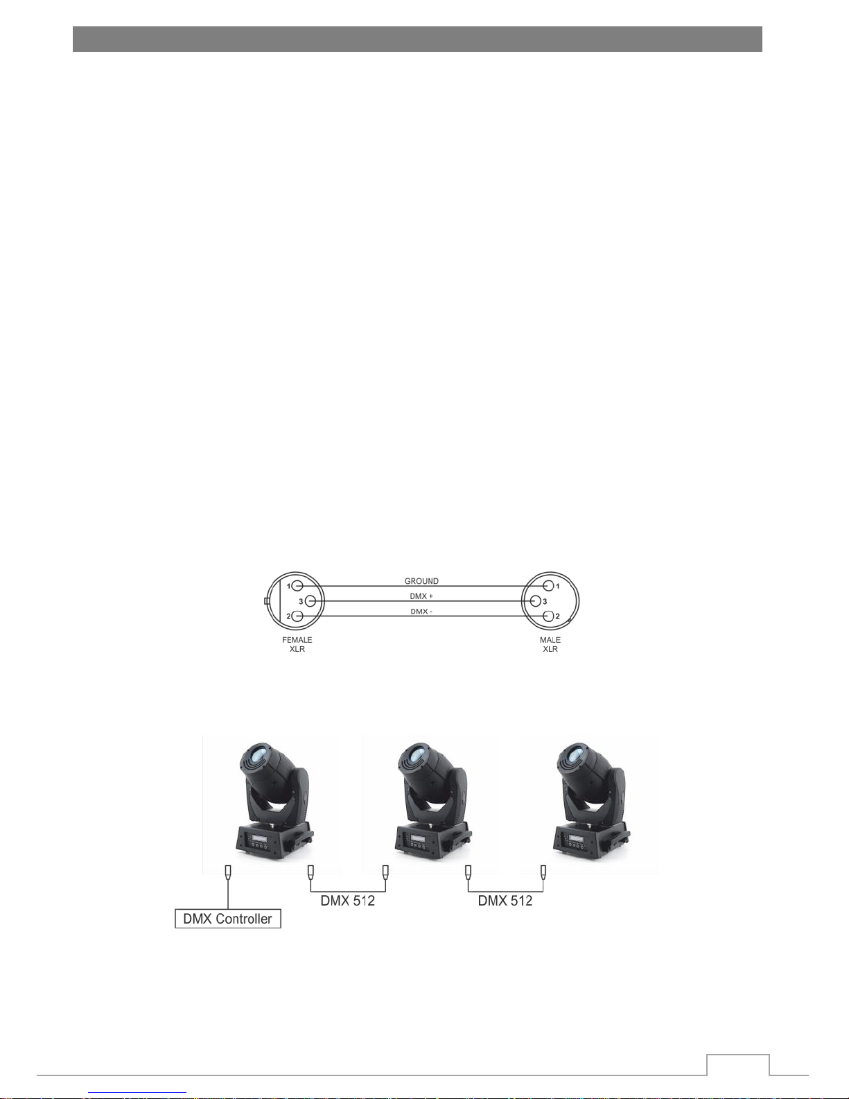
5.1 Connecting DMX signal
The connection is performed using cable with XLR-female -> XLR-Male plugs.
To link fixtures together you must obtain data cables. If you choose to create your own cable please use data-
grade cables that can carry a high quality signal and are less prone to electromagnetic interference.
Standard microphone cables cannot transmit DMX data reliably over long distances. The cable will have the
following characteristics:
2-conductor twisted pair plus a shield.
maximum capacitance between conductors-30 pF/ft.
maximum capacitance between conductor and shield -55pF/ft.
maximum resistance of 20 ohms/1000ft.
nominal impedance 100-140 ohms.
5.2 Fixture linking
Setting up a DMX serial data link: at first link the first light and DMX control through XLR-connection signal
cable, then connect the light in series.
You will need a serial data link to run light show of one or more fixtures using a DMX-512 controller or to
run synchronized on two or more fixtures set to a master/slave operating mode. The combined number of
channels required by all the fixtures on a serial data link determines the number of fixtures the data link can
support.
 Loading...