

Page 1
REVISION DATE
20170427
DOCUMENT NUMBER
NOTICE The manufacturer will accept no responsability for any electrical
damage resulting from improper installation of this product, be that either
damage to the vehicle itself or to the installed device. This device must be installed by a certified technician. Please review the Installation Guide carefully
before beginning any work.
BEFORE INSTALLATION
1- Connect module to computer
2- Login to Weblink account
3- Flash firmware to module (module is not preloaded with firmware)
4- Use accessories accordingly (accessories are sold separately)
U.S. Patent No. 8,856,780
INSTALL GUIDE
FLCGMRSGM10FLRSGM10EN
HARDWARE
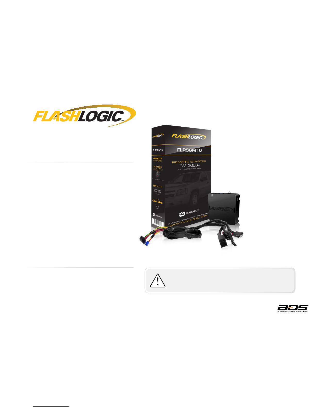
FLRSGM10
ACCESSORIES
FLPROG REQUIRED
FLRF1/2/4 OPTIONAL
CARLINK ASCL2 OPTIONAL
FIRMWARE
FLCGMRSGM10FLRSGM10
www.flashlogic.comAutomotive Data Solutions Inc. © 2017
38693
Page 2
U.S. Patent No. 8,856,780
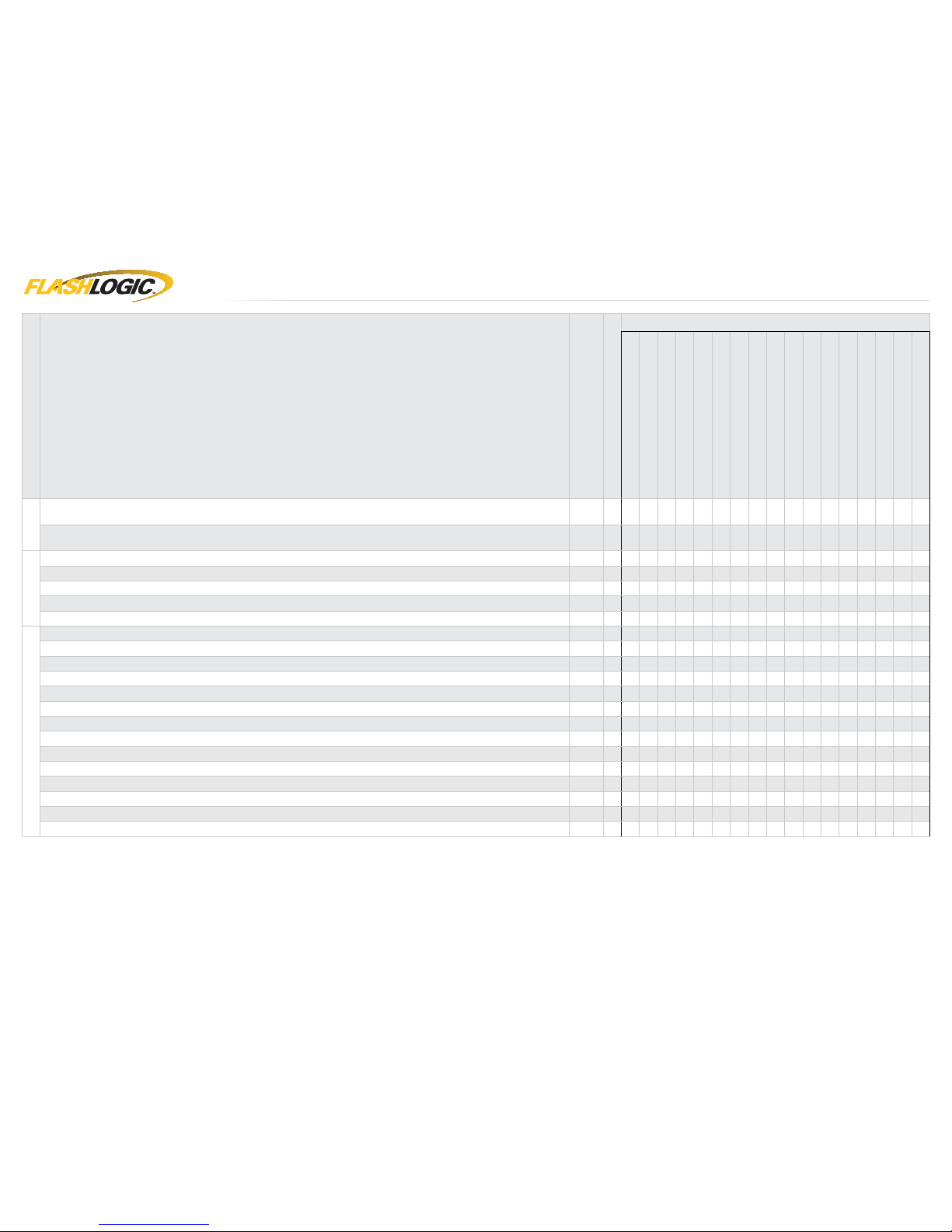
VEHICLE LIST - 1 OF 2
* If equiped
** If activated in vehicle settings
MAKE
MODEL
YEAR
INSTALL TYPE
FEATURES
DATA IMMOBILIZER BYPASS
3X LOCK START/STANDALONE MOD.
ARM OEM ALARM
DISARM OEM ALARM
DOOR LOCK
DOOR UNLOCK
PRIORITY UNLOCK
TRUNK/HATCH RELEASE*
TAILGATE WINDOW RELEASE
HEATED SEATS CTRL
PUDDLE LIGHT CTRL**
TACHOMETER OUTPUT
DOOR STATUS OUTPUT
HOOD STATUS OUTPUT*
TRUNK STATUS OUTPUT
BRAKE PEDAL STATUS OUTPUT
RAP SHUTDOWN CTRL
BUICK
Enclave STD key AT 08-17 1 • • • • • • • • • • • • • • •
Lucerne STD key AT 06-11 1 • • • • • • • • • • • • • • • •
CADILLAC
CTS STD key AT 08-14 1 • • • • • • • • • • • • • • • •
DTS STD key AT 06-11 1 • • • • • • • • • • • • • • • •
Escalade / ESV / Hybrid STD key AT 07-14 1 • • • • • • • • • • • • • • • • •
Escalade EXT STD key AT 07-13 1 • • • • • • • • • • • • • • •
SRX STD key AT 07-09 2 • • • • • • • • • • • • • • • • •
CHEVROLET
Avalanche STD key AT 07-13 1 • • • • • • • • • • • • • • •
Caprice STD key AT 11-13 1 • • • • • • • • • • • • • • • •
Captiva Sport STD key AT 08-15 2 • • • • • • • • • • • • • •
Equinox STD key AT 07-09 1 • • • • • • • • • • • • •
Express STD key AT 08-17 1 • • • • • • • • • • • •
Impala STD key AT 06-13 1 • • • • • • • • • • • • • •
Impala limited STD key AT 13-16 1 • • • • • • • • • • • • • •
Monte Carlo STD key AT 06-09 1 • • • • • • • • • • • • • •
Silverado / Hybrid STD key AT 07-13 1 • • • • • • • • • • • • •
Silverado / Hybrid Premium Package STD key AT 07-13 1 • • • • • • • • • • • • • •
Suburban STD key AT 07-14 1 • • • • • • • • • • • • • • • • •
Tahoe / Hybrid STD key AT 07-14 1 • • • • • • • • • • • • • • • • •
Traverse STD key AT 09-17 1 • • • • • • • • • • • • • • •
Traverse with Auto Up/Down Windows STD key AT 09-17 1 • • • • • • • • • •
• • • • • •
www.flashlogic.comAutomotive Data Solutions Inc. © 2017 FLCGMRSGM10FLRSGM10EN
PAGE 2 OF 20
• 20170427
DOC.: #38693
Page 3
U.S. Patent No. 8,856,780
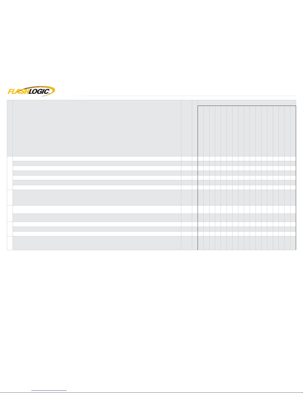
VEHICLE LIST - 2 OF 2
MAKE
MODEL
YEAR
INSTALL TYPE
FEATURES
DATA IMMOBILIZER BYPASS
3X LOCK REMOTE START
ARM OEM ALARM
DISARM OEM ALARM
DOOR LOCK
DOOR UNLOCK
PRIORITY UNLOCK
TRUNK/HATCH RELEASE*
TAILGATE WINDOW RELEASE
HEATED SEATS CTRL
PUDDLE LIGHT CTRL**
TACHOMETER OUTPUT
DOOR STATUS OUTPUT
HOOD STATUS OUTPUT*
TRUNK STATUS OUTPUT
BRAKE PEDAL STATUS OUTPUT
RAP SHUTDOWN CTRL
GMC
Acadia STD key AT 07-16 1 • • • • • • • • • • • • •
Acadia with Auto Up/Down Windows STD key AT 07-16 1 • • • • • • • • • • • • • •
Acadia limited STD key AT 17 1 • • • • • • • • • • • • • •
Savana STD key AT 08-17 1 • • • • • • • • • • •
Sierra STD key AT 07-13 1 • • • • • • • • • • • • •
Sierra Premium Package STD key AT 07-13 1 • • • • • • • • • • • • • •
Yukon / XL / Denali / Hybrid STD key AT 07-14 1 • • • • • • • • • • • • • • • • •
HUMMER
H2 STD key AT 08-09 1 • • • • • • • • • • • • • • • • •
PONTIAC
G8 STD key AT 08-09 1 • • • • • • • • • • • • •
Torrent STD key AT 07-09 1 • • • • • • • • • • • • •
SATURN
Outlook STD key AT 07-10 1 • • • • • • • • • • • • •
Outlook with Auto Up/Down Windows STD key AT 07-10 1 • • • • • • • • • • • • • •
Vue / Hybrid STD key AT 08-10 2 • • • • • • • • • • • • •
SUZUKI
XL7 STD key AT 07-09 1 • • • • • • • • • • • • •
* If equiped
** If activated in vehicle settings
www.flashlogic.comAutomotive Data Solutions Inc. © 2017 FLCGMRSGM10FLRSGM10EN
PAGE 3 OF 20
• 20170427
DOC.: #38693
Page 4
U.S. Patent No. 8,856,780
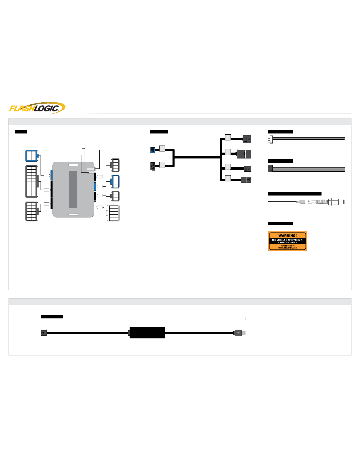
BOX CONTENTS - 1 OF 1
VS3VS3
VS4VS4
VS1VS1
VS2VS2
MS1MS1
MS2MS2
3
6
4
1
2
5
C
B
A
F
G
E
D
7
9
3
10
8
11
13
14
12
15
17
18
19
20
16
6
4
1
2
5
7
9
3
10
8
11
12
6
4
1
2
5
2
1
3
7
9
3
10
8
6
4
1
2
5
2
1
3
4
2
1
3
4
BOX CONTENTS
T-HARNESS 1
AFTERMARKET HOOD SWITCH AND CABLE
WARNING STICKER
10 PIN CONNECTOR
12 PIN CONNECTOR
BLUE
PROGRAMMING
BUTTON
LED 2
LED 1
MODULE
BLACK
BLACK
BLACK
RF PORT/
WEBLINK PORT
BLACK
BLUE
TELEMATIC
PORT
WHITE
WEBLINK CABLE (required accessory sold separately)
WEBLINK CABLE
COMPUTER
USB PORT
4 PIN BLACK CABLE
MODULE
WEBLINK PORT
www.flashlogic.comAutomotive Data Solutions Inc. © 2017 FLCGMRSGM10FLRSGM10EN
PAGE 4 OF 20
• 20170427
DOC.: #38693
Page 5
U.S. Patent No. 8,856,780
www.flashlogic.comAutomotive Data Solutions Inc. © 2017 FLCGMRSGM10FLRSGM10EN
PAGE 5 OF 20
• 20170427
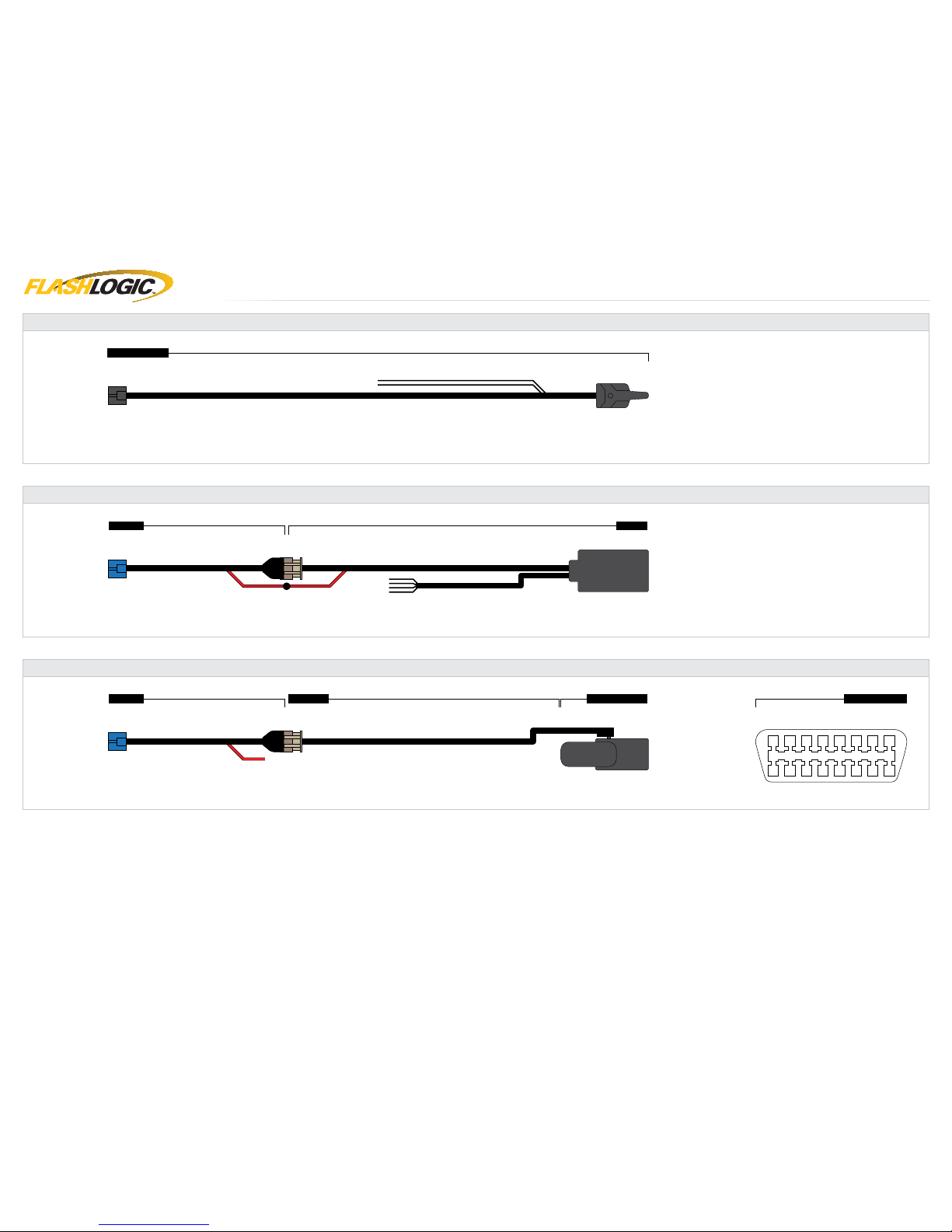
COMPATIBLE ACCESSORIES - 1 OF 1
FLRF1/2/4 RF KIT
RF KIT (accessories sold separately)
(NC)
ANTENNA
MODULE
RF PORT
FLHRNTM
TELEMATIC KIT (accessories sold separately)
(NC)
CARLINK
MODULE
TELEMATIC PORT
10 11 12 13 14 15 16
1 2 3 4 5 6 7 8
9
FLHRNTM
TELEMATIC KIT (accessories sold separately)
MODULE
TELEMATIC PORT
CAR CONNECTIONPN 4120260
OBDII CONNECTOR
VEHICLE
OBDII PORT
(NC)
DOC.: #38693
Page 6
U.S. Patent No. 8,856,780
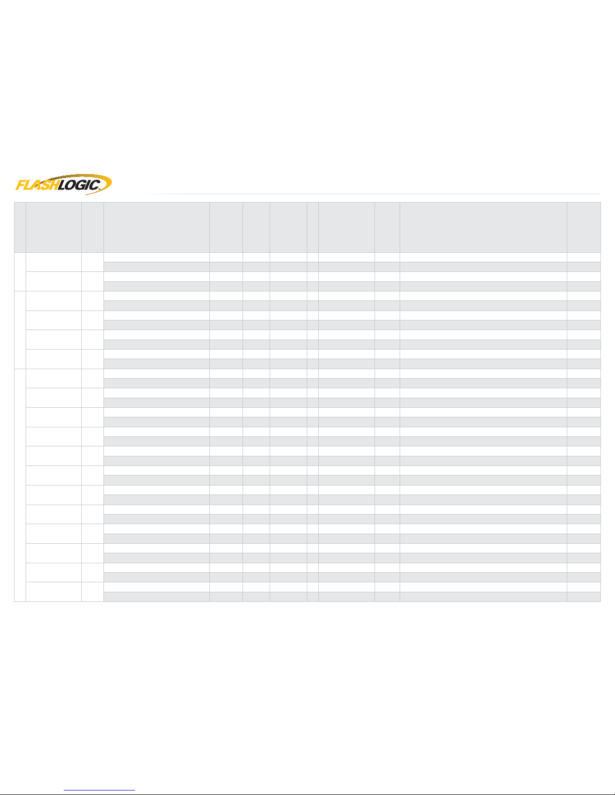
TYPE 1 - WIRE CHART - 1 OF 2
MAKE
MODEL
YEAR
WIRE
DESCRIPTION
CONNECTOR
NAME
CONNECTOR
COLOR
CONNECTOR
TYPE
POSITION
WIRE
COLOR
POLARITY
MODULE
LOCATION
COMPONENT
LOCATOR
BUICK
Enclave 08-17
Driver Door Pin ~ ~ ~ ~ ~ ~ Do not connect. Supported by data ~
Parking Light ~ ~ ~ ~ Brown/White (-) At headlight switch ~
Lucerne 06-11
Driver Door Pin ~ ~ ~ ~ ~ ~ Do not connect. Supported by data ~
Parking Light ~ ~ ~ ~ LtBlue/Tan (-) At headlight switch ~
CADILLAC
CTS 08-14
Driver Door Pin ~ ~ ~ ~ ~ ~ Do not connect. Supported by data ~
Parking Light ~ ~ ~ ~ Brown/White (-) At headlight switch ~
DTS 06-11
Driver Door Pin ~ ~ ~ ~ ~ ~ Do not connect. Supported by data ~
Parking Light ~ ~ ~ ~ LtBlue (-) At headlight switch ~
Escalade / ESV /
Hybrid
07-14
Driver Door Pin ~ ~ ~ ~ ~ ~ Do not connect. Supported by data ~
Parking Light ~ ~ ~ ~ LtBlue (-) At headlight switch ~
Escalade EXT 07-13
Driver Door Pin ~ ~ ~ ~ ~ ~ Do not connect. Supported by data ~
Parking Light ~ ~ ~ ~ LtBlue (-) At headlight switch ~
CHEVROLET
Avalanche 07-13
Driver Door Pin ~ ~ ~ ~ ~ ~ Do not connect. Supported by data ~
Parking Light ~ ~ ~ ~ LtBlue (-) At headlight switch ~
Caprice 11-13
Driver Door Pin ~ ~ ~ ~ Gray/Black (-) Driver kick panel ~
Parking Light ~ ~ ~ ~ Brown/White (-) At headlight switch ~
Equinox 07-09
Driver Door Pin ~ ~ ~ ~ Gray/Black (-) Driver kick panel ~
Parking Light ~ ~ ~ ~ Brown/White (-) At headlight switch ~
Express 08-17
Driver Door Pin ~ ~ ~ ~ Gray/Black (-) Driver kick panel ~
Parking Light ~ ~ ~ ~ LtBlue (-) At headlight switch ~
Impala 06-13
Driver Door Pin ~ ~ ~ ~ Gray/Black (-) Driver kick panel ~
Parking Light ~ ~ ~ ~ Brown/White (-) At headlight switch ~
Impala limited 13-16
Driver Door Pin ~ ~ ~ ~ Gray/Black (-) Driver kick panel ~
Parking Light ~ ~ ~ ~ Brown/White (-) At headlight switch ~
Monte Carlo 06-09
Driver Door Pin ~ ~ ~ ~ Gray/Black (-) Driver kick panel ~
Parking Light ~ ~ ~ ~ Brown/White (-) At headlight switch ~
Silverado / Hybrid 07-13
Driver Door Pin ~ ~ ~ ~ Gray/Black (-) Driver kick panel ~
Parking Light ~ ~ ~ ~ LtBlue (-) At headlight switch ~
Silverado / Hybrid
Premium Package
07-13
Driver Door Pin ~ ~ ~ ~ ~ ~ Do not connect. Supported by data ~
Parking Light ~ ~ ~ ~ LtBlue (-) At headlight switch ~
Suburban 07-14
Driver Door Pin ~ ~ ~ ~ ~ ~ Do not connect. Supported by data ~
Parking Light ~ ~ ~ ~ LtBlue (-) At headlight switch ~
Tahoe / Hybrid 07-14
Driver Door Pin ~ ~ ~ ~ ~ ~ Do not connect. Supported by data ~
Parking Light ~ ~ ~ ~ LtBlue (-) At headlight switch ~
Traverse 09-17
Driver Door Pin ~ ~ ~ ~ Gray/Black (-) Driver kick panel ~
Parking Light ~ ~ ~ ~ Brown/White (-) At headlight switch ~
www.flashlogic.comAutomotive Data Solutions Inc. © 2017 FLCGMRSGM10FLRSGM10EN
PAGE 6 OF 20
• 20170427
DOC.: #38693
Page 7
U.S. Patent No. 8,856,780
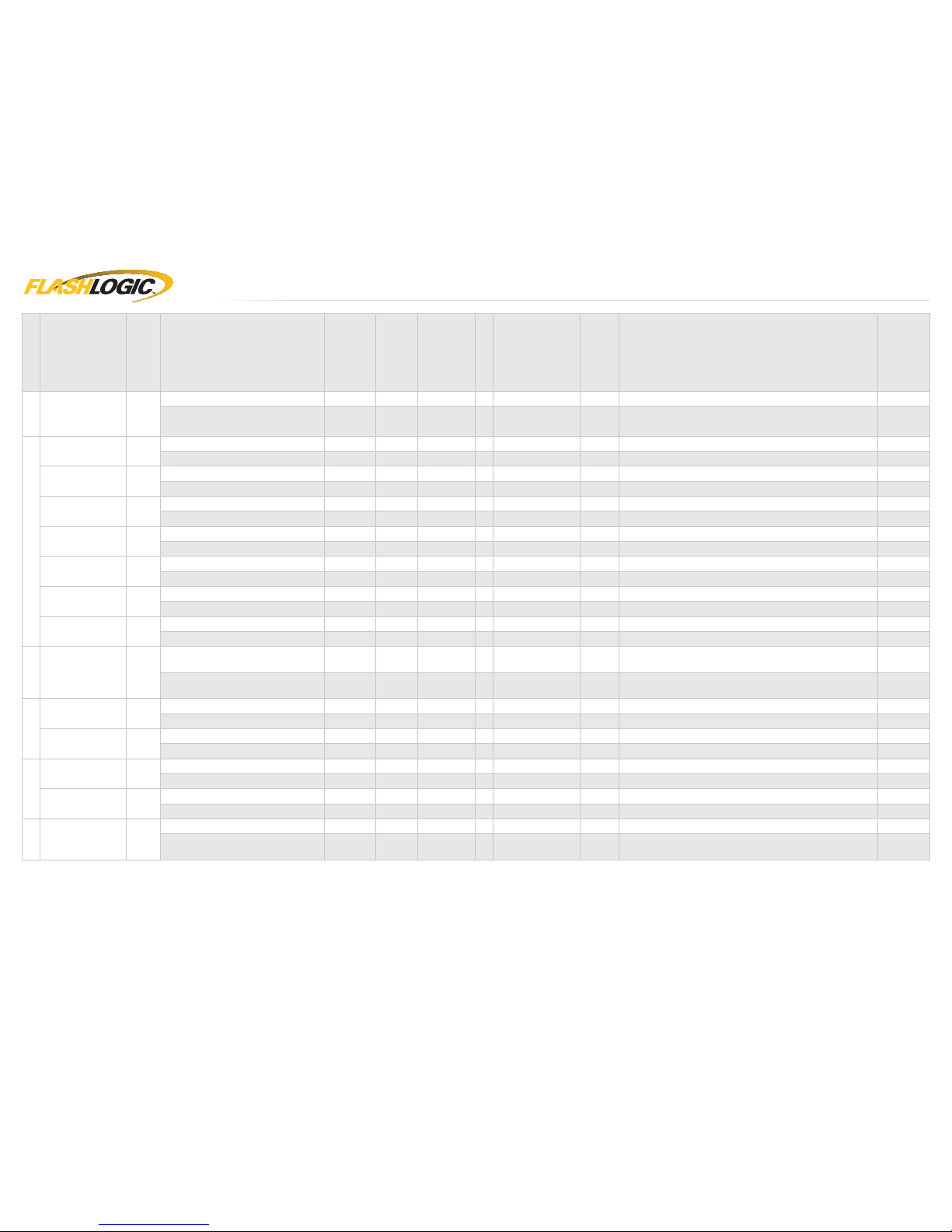
TYPE 1 - WIRE CHART - 2 OF 2
MAKE
MODEL
YEAR
WIRE
DESCRIPTION
CONNECTOR
NAME
CONNECTOR
COLOR
CONNECTOR
TYPE
POSITION
WIRE
COLOR
POLARITY
MODULE
LOCATION
COMPONENT
LOCATOR
CHEVY
Traverse with Auto
Up/Down Windows
09-17
Driver Door Pin ~ ~ ~ ~ ~ ~ Do not connect. Supported by data ~
Parking Light ~ ~ ~ ~ Brown/White (-) At headlight switch ~
GMC
Acadia 07-16
Driver Door Pin ~ ~ ~ ~ Gray/Black (-) Driver kick panel ~
Parking Light ~ ~ ~ ~ Brown/White (-) At headlight switch ~
Acadia with Auto
Up/Down Windows
07-16
Driver Door Pin ~ ~ ~ ~ ~ ~ Do not connect. Supported by data ~
Parking Light ~ ~ ~ ~ Brown/White (-) At headlight switch ~
Acadia limited 17
Driver Door Pin ~ ~ ~ ~ ~ ~ Do not connect. Supported by data ~
Parking Light ~ ~ ~ ~ Brown/White (-) At headlight switch ~
Savana 08-17
Driver Door Pin ~ ~ ~ ~ Gray/Black (-) Driver kick panel ~
Parking Light ~ ~ ~ ~ LtBlue (-) At headlight switch ~
Sierra 07-13
Driver Door Pin ~ ~ ~ ~ Gray/Black (-) Driver kick panel ~
Parking Light ~ ~ ~ ~ LtBlue (-) At headlight switch ~
Sierra Premium
Package
07-13
Driver Door Pin ~ ~ ~ ~ ~ ~ Do not connect. Supported by data ~
Parking Light ~ ~ ~ ~ LtBlue (-) At headlight switch ~
Yukon / XL /
Denali / Hybrid
07-14
Driver Door Pin ~ ~ ~ ~ ~ ~ Do not connect. Supported by data ~
Parking Light ~ ~ ~ ~ LtBlue (-) At headlight switch ~
HUMMER
H2 08-09
Driver Door Pin ~ ~ ~ ~ ~ ~ Do not connect. Supported by data ~
Parking Light ~ ~ ~ ~ LtBlue (-) At headlight switch ~
PONTIAC
G8 08-09
Driver Door Pin ~ ~ ~ ~ Gray/Black (-) Driver kick panel ~
Parking Light ~ ~ ~ ~ Brown/White (-) At headlight switch ~
Torrent 07-09
Driver Door Pin ~ ~ ~ ~ Gray/Black (-) Driver kick panel ~
Parking Light ~ ~ ~ ~ Brown/White (-) At headlight switch ~
SATURN
Outlook 07-10
Driver Door Pin ~ ~ ~ ~ Gray/Black (-) Driver kick panel ~
Parking Light ~ ~ ~ ~ Brown/White (-) At headlight switch ~
Outlook with Auto
Up/Down Windows
07-10
Driver Door Pin ~ ~ ~ ~ ~ ~ Do not connect. Supported by data ~
Parking Light ~ ~ ~ ~ Brown/White (-) At headlight switch ~
SUZUKI
XL7 07-09
Driver Door Pin ~ ~ ~ ~ Gray/Black (-) Driver kick panel ~
Parking Light ~ ~ ~ ~ Brown/White (-) At headlight switch ~
www.flashlogic.comAutomotive Data Solutions Inc. © 2017 FLCGMRSGM10FLRSGM10EN
PAGE 7 OF 20
• 20170427
DOC.: #38693
Page 8

U.S. Patent No. 8,856,780
A1
B1
A1
A2
B1
B2
VS3VS3
VS4VS4
VS1VS1
VS2VS2
MS1MS1
MS2MS2
A
B
7
9
3
10
8
11
13
14
12
15
17
18
19
20
16
6
4
1
2
5
3
6
4
1
2
5
C
7
9
3
10
8
11
12
6
4
1
2
5
D
7
9
3
10
8
6
4
1
2
5
C
B
A
F
G
E
D
DRIVER DOOR PIN (-)
PARKING LIGHT (-)
01 BROWN/BLACK - PARKING LIGHT (-) OUTPUT
02 GRAY - RAP SHUTDOWN (-) OUTPUT
PK3 CONNECTOR
IGNITION CONNECTOR
IGNITION HARNESS
PK3 HARNESS
CONNECT IF NOT SUPPORTED BY DATA
TYPE 1 - WIRING DIAGRAM - 1 OF 1
VEHICLE IGNITION SWITCH
VEHICLE
MODULE
HORN (-)
11 GRAY/GREEN - HORN (-) OUTPUT
OPTIONAL
AFTERMARKET HOOD SWITCH (-)
04 GRAY/WHITE - HOOD STATUS (-) INPUT
WITHOUT OEM HOOD SWITCH:
INSTALL AND CONNECT TO
AFTERMARKET HOOD SWITCH
TELEMATIC PORT
RF PORT/WEBLINK PORT
www.flashlogic.comAutomotive Data Solutions Inc. © 2017 FLCGMRSGM10FLRSGM10EN
PAGE 8 OF 20
• 20170427
DOC.: #38693
Page 9

U.S. Patent No. 8,856,780
TYPE 2 - WIRE CHART - 1 OF 1
MAKE
MODEL
YEAR
WIRE
DESCRIPTION
CONNECTOR
NAME
CONNECTOR
COLOR
CONNECTOR
TYPE
POSITION
WIRE
COLOR
POLARITY
MODULE
LOCATION
COMPONENT
LOCATOR
CADILLAC
SRX
STD key
07-09
Driver Door Pin ~ ~ ~ ~ ~ ~ Do not connect. Supported by data ~
Parking Light ~ ~ ~ ~ LtBlue (-) At headlight switch ~
Ignition ~ Green 06 pin 02 Pink (+) Ignition connector ~
Passlock ~ Green 06 pin 05 White (+) Ignition connector ~
CHEVROLET
Captiva Sport 4cyl
/ Hybrid
STD key
08-15
Driver Door Pin ~ ~ ~ ~ ~ ~ Do not connect. Supported by data ~
Parking Light ~ ~ ~ ~ LtBlue (-) At headlight switch ~
Ignition ~ Black 06 pin 01 Pink (+) Ignition connector ~
Passlock ~ Black 06 pin 05 White/Black (+) Ignition connector ~
Captiva Sport 6cyl
STD key
08-15
Driver Door Pin ~ ~ ~ ~ ~ ~ Do not connect. Supported by data ~
Parking Light ~ ~ ~ ~ LtBlue (-) At headlight switch ~
Ignition ~ Green 06 pin 03 Pink (+) Ignition connector ~
Passlock ~ Green 06 pin 04 White/Black (+) Ignition connector ~
SATURN
Vue 4cyl / Hybrid
STD key
08-10
Driver Door Pin ~ ~ ~ ~ ~ ~ Do not connect. Supported by data ~
Parking Light ~ ~ ~ ~ LtBlue (-) At headlight switch ~
Ignition ~ Black 06 pin 01 Pink (+) Ignition connector ~
Passlock ~ Black 06 pin 05 White/Black (+) Ignition connector ~
Vue 6cyl
STD key
08-10
Driver Door Pin ~ ~ ~ ~ ~ ~ Do not connect. Supported by data ~
Parking Light ~ ~ ~ ~ LtBlue (-) At headlight switch ~
Ignition ~ Green 06 pin 03 Pink (+) Ignition connector ~
Passlock ~ Green 06 pin 04 White/Black (+) Ignition connector ~
www.flashlogic.comAutomotive Data Solutions Inc. © 2017 FLCGMRSGM10FLRSGM10EN
PAGE 9 OF 20
• 20170427
DOC.: #38693
Page 10

U.S. Patent No. 8,856,780
A1
B1
A1
B1
B2
VS3VS3
VS4VS4
VS1VS1
VS2VS2
MS1MS1
MS2MS2
A
B
7
9
3
10
8
11
13
14
12
15
17
18
19
20
16
6
4
1
2
5
3
6
4
1
2
5
C
7
9
3
10
8
11
12
6
4
1
2
5
D
7
9
3
10
8
6
4
1
2
5
1
2 3 4
6
5
C
B
A
F
G
E
D
DRIVER DOOR PIN (-)
PARKING LIGHT (-)
01 BROWN/BLACK - PARKING LIGHT (-) OUTPUT
02 GRAY - RAP SHUTDOWN (-) OUTPUT
PK3 CONNECTOR
(NC)
PK3 HARNESS
CONNECT IF NOT SUPPORTED BY DATA
TYPE 2 - WIRING DIAGRAM - 1 OF 1
VEHICLE IGNITION SWITCH
VEHICLE
MODULE
HORN (-)
11 GRAY/GREEN - HORN (-) OUTPUT
OPTIONAL
AFTERMARKET HOOD SWITCH (-)
04 GRAY/WHITE - HOOD STATUS (-) INPUT
WITHOUT OEM HOOD SWITCH:
INSTALL AND CONNECT TO
AFTERMARKET HOOD SWITCH
REFER TO WIRE CHART
FOR WIRE COLOR AND LOCATION
IGNITION (+)
PASSLOCK (+)
PINK
YELLOW
CUT CONNECTOR
FROM HARNESS
IGNITION CONNECTOR
TELEMATIC PORT
RF PORT/WEBLINK PORT
www.flashlogic.comAutomotive Data Solutions Inc. © 2017 FLCGMRSGM10FLRSGM10EN
PAGE 10 OF 20
• 20170427
DOC.: #38693
Page 11

U.S. Patent No. 8,856,780
01
02
03
OFF
ACC ON
START
04
OFF
ACC ON
START
05
06
OFF
ACC ON
START
07
08
OFF
ACC ON
START
09
MODULE PROGRAMMING PROCEDURE - 1 OF 1
Close driver door.
Re-open driver door to wake up data bus.
Insert key into ignition.
Turn key to ACC position.
Wait, LED 1 will turn solid RED.
Turn key to ON position.
Wait, LED 1 will turn solid GREEN for 2
seconds. (This may take up to 1 minute.)
Turn key to OFF position.
Module Programming Procedure completed.
www.flashlogic.comAutomotive Data Solutions Inc. © 2017 FLCGMRSGM10FLRSGM10EN
PAGE 11 OF 20
• 20170427
DOC.: #38693
Page 12

U.S. Patent No. 8,856,780
>>
01
02
ENGINE
START
STOP
OFF ACC ON START
ON
03
04
ENGINE
START
STOP
OFF ACC ON STARTOFF
05
>>
VALET MODE PROGRAMMING PROCEDURE - 1 OF 1
NOTE: In Valet Mode, the Remote starter is not
functional. Keyless entry, Lock and Unlock will
remain functional. See RF kit user manual for
alternate valet mode programming.
Time restriction. Complete next step within 7
seconds.
Cycle ignition ON fi ve times [5x OFF/ON]
rapidly.
Wait, LED 1 will turn solid RED for 2 seconds.
Set ignition to OFF position.
Valet Mode Programming Procedure
completed.
To exit valet mode: repeat steps 1 to 5.
www.flashlogic.comAutomotive Data Solutions Inc. © 2017 FLCGMRSGM10FLRSGM10EN
PAGE 12 OF 20
• 20170427
DOC.: #38693
Page 13

U.S. Patent No. 8,856,780
AFTERMARKET REMOTE PROGRAMMING - 1 OF 1
AFTERMARKET REMOTE PROGRAMMING:
NOTES
I All aftermarket remotes must be programmed to the
RF-Kit.
Refer to the RF-Kit user guide for aftermarket remote
features and programming procedures.
www.flashlogic.comAutomotive Data Solutions Inc. © 2017 FLCGMRSGM10FLRSGM10EN
PAGE 13 OF 20
• 20170427
DOC.: #38693
Page 14

U.S. Patent No. 8,856,780
>>
>>
>>
01
ENGINE
START
STOP
OFF ACC ON STARTOFF
02
03
[X]
04
05
[Y]
06
07
[Z]
08
[Z]
09
10
11
[Y]
12
13
14
>>
MODULE NAVIGATION PROCEDURE - 1 OF 1
It is mandatory to exit the Module Navigation
at the end of this procedure. Failure to exit the
Module Navigation will drain vehicle battery.
To exit the Module Navigation at any time:
Follow STEP 13.
Module must be programmed to the vehicle.
Use the Module Navigation Chart on the next
page.
Set ignition to OFF position.
TO ACCESS THE MENUS: Press and hold
programming button until LED 1 turns solid
GREEN.
IN THE MENUS: Press the programming
button as many times as the menu number
indicates. LED 1 will fl ash GREEN an equal
amount of times continuously.
TO ACCESS THE OPTIONS: Press and hold
programming button until LED 1 turns solid
RED.
IN THE OPTIONS: Press the programming
button as many times as the option number
indicates. LED 1 will fl ash RED an equal
amount of times continuously.
TO ACCESS THE SETTINGS: Press and hold
programming button until LED 1 turns solid
GREEN.
LED 1 will flash GREEN as many times as
the current (or default) setting number,
continuously.
IN THE SETTINGS: Press the programming
button as many times as necessary to access
your setting. LED 1 will fl ash GREEN an equal
amount of times continuously.
To return to the MENUS: exit the Module
Navigation and redo the Module Navigation
Procedure.
To save and return to the OPTIONS: Press and
hold programming button until LED 1 turns
solid RED.
LED 1 will fl ash RED as many times as the
current option number continuously.
Configure every other setting and proceed to
step 13.
MANDATORY: EXIT MODULE NAVIGATION.
Press and hold programming button for 7
seconds. LED 1 will fl ash RED rapidly. Release
programming button. LED 1 will turn OFF.
Module navigation completed.
Failure to exit the Module Navigation will drain
vehicle battery.
www.flashlogic.comAutomotive Data Solutions Inc. © 2017 FLCGMRSGM10FLRSGM10EN
PAGE 14 OF 20
• 20170427
DOC.: #38693
Page 15

U.S. Patent No. 8,856,780
MODULE NAVIGATION CHART - 1 OF 2
MODULE NAVIGATION CHART:
NOTES
[X] MENUS
[Y] OPTIONS
[Z] SETTINGS
I Default settings are listed in bold.
01 CONFIGURATION
01 DISARM/UNLOCK BEFORE START
01 OFF
II Make sure the option is covered on the vehicle before
attempting to change the setting.
02 ON
02 RELOCK AFTER START
01 OFF
02 ON
03 RELOCK AFTER SHUTDOWN
01 OFF
02 ON
04 FORCE UNLOCK ALL ON FIRST PRESS
01 OFF
02 ON
05 TAKEOVER
01 ENABLE
02 DISABLE*
06 N/A 01 N/A
07 FACTORY KEYLESS RS SEQUENCE
01 DISABLE
02 N/A
03 LOCK + UNLOCK + LOCK
04 LOCK + LOCK + LOCK
08 MODULE RUN TIME
01 03 MIN
02 05 MIN
03 10 MIN
04 15 MIN
05 25 MIN
06 30 MIN
07 35 MIN
08 15 MIN
09 WAIT TO START DELAY
01 02 SEC
02 05 SEC
03 08 SEC
04 10 SEC
05 15 SEC
06 20 SEC
07 25 SEC
08 30 SEC
10 N/A 01 N/A
11 N/A 01 N/A
12 N/A 01 N/A
13 N/A 01 N/A
*Vehicle will shutdown when a door is opened.
www.flashlogic.comAutomotive Data Solutions Inc. © 2017 FLCGMRSGM10FLRSGM10EN
PAGE 15 OF 20
• 20170427
DOC.: #38693
Page 16

U.S. Patent No. 8,856,780
MODULE NAVIGATION CHART - 2 OF 2
MODULE NAVIGATION CHART:
NOTES
[X] MENUS
[Y] OPTIONS
[Z] SETTINGS
01 CONFIGURATION
14 HORN EVENT TRIGGER
01 DOUBLE LOCK
02 LOCK + UNLOCK
03 LOCK + UNLOCK + START
04 DOUBLE LOCK + START
15 HORN CHIRPS WIDTH
01 30 mSEC
02 15 mSec
03 60 mSec
02-07 Technical Support only 01 N/A 01 N/A
*Vehicle will shutdown when a door is opened.
www.flashlogic.comAutomotive Data Solutions Inc. © 2017 FLCGMRSGM10FLRSGM10EN
PAGE 16 OF 20
• 20170427
DOC.: #38693
Page 17

U.S. Patent No. 8,856,780
REMOTE STARTER ERROR CODES - 1 OF 1
REMOTE STARTER ERROR CODES:
NOTES
[X] NUMBER OF
PARKING LIGHT
FLASHES
DIAGNOSTIC
I WARNING: The following applies only when the parking
lights are connected and supported by the system.
03 Foot brake is ON.
04 Hood is open.
II After a remote starter failure, the parking lights will fl ash
[X] number times to indicate an error code. See table.
05 Engine tach signal is lost.
06 System is in Valet Mode.
07 Vehicle is moving (VSS).
08 Glow plug timeout error.
09 RS not synchronized. Start vehicle with OEM key for 15 sec before trying a new RS sequence.
10 N/A
11 N/A
12 N/A
13 N/A
14 N/A
15 N/A
16 CAN communication failure during RS sequence.
www.flashlogic.comAutomotive Data Solutions Inc. © 2017 FLCGMRSGM10FLRSGM10EN
PAGE 17 OF 20
• 20170427
DOC.: #38693
Page 18

U.S. Patent No. 8,856,780
MODULE DIAGNOSTICS - 1 OF 1
TEST MODULE
LED 1 STATUS
DIAGNOSTIC
I DURING PROGRAMMING
Flashing RED Missing/wrong information from fi rmware or vehicle.
Solid RED Module waiting for more vehicle information.
Flashing GREEN Additional steps required to complete module programming.
Solid GREEN then OFF Module correctly programmed.
OFF No activity or module already programmed.
II DURING REMOTE START
Flashing RED Module incorrectly programmed.
Solid RED Module incorrectly programmed.
Flashing GREEN Module correctly programmed and operational.
Solid GREEN then OFF Reset in progress.
OFF Invalid ground when running status from remote starter.
III WITH IGNITION OFF
Flashing RED Module incorrectly programmed or connected.
Solid RED Module not programmed. Waiting for more vehicle information.
Flashing GREEN False ground when running status from remote starter.
Solid GREEN then OFF Reset in progress.
OFF Module at rest and ready for a remote start sequence.
www.flashlogic.comAutomotive Data Solutions Inc. © 2017 FLCGMRSGM10FLRSGM10EN
PAGE 18 OF 20
• 20170427
DOC.: #38693
Page 19

U.S. Patent No. 8,856,780
01
02
03
04
05
06
07
08
>>
MODULE RESET PROCEDURE - 1 OF 1
Disconnect all connectors from module except
the BLACK 20-PIN connector.
Disconnect the BLACK 20-PIN connector.
PRESS AND HOLD the module’s programming
button while connecting the BLACK 20-PIN
connector.
Wait, LED 1 will flash RED. RELEASE
programming button.
LED 1 will turn RED for 2 seconds.
Module RESET completed.
Reconnect all connectors.
Repeat programming procedure.
Failure to follow procedure may result with a
DTC or a CHECK ENGINE error message.
www.flashlogic.comAutomotive Data Solutions Inc. © 2017 FLCGMRSGM10FLRSGM10EN
PAGE 19 OF 20
• 20170427
DOC.: #38693
Page 20

U.S. Patent No. 8,856,780
INSTALLATION CHECKLIST - 1 OF 1
1 WARNING: Vehicle engine will start many times. Test in a well ventilated area.
2 Close all vehicle doors, hood and trunk.
3 Press the LOCK button once [1x] on the aftermarket keyfob.
¨
Question 1: Do the doors lock?
YES: Go to next step.
¨
NO: Verify the remote programming, the RF connections and the wired door lock/unlock
connections as illustrated in the wiring diagram, if applicable. Repeat the test and call
technical support, if the problem persists.
4 Press the UNLOCK button once [1x] on the aftermarket keyfob.
¨
Question 2: Do the doors unlock?
YES: Go to next step.
¨
NO: Verify the remote programming, the RF connections and the wired door lock/unlock
connections as illustrated in the wiring diagram, if applicable. Repeat the test and call
technical support, if the problem persists.
5 Press the TRUNK release button once [1x] on the aftermarket keyfob if supported.
¨
Question 3: Does the trunk or hatch open/unlock?
YES: Close trunk or hatch and go to next step.
¨
NO: Verify the remote programming, the RF connections and the wired trunk/hatch
connections as illustrated in the wiring diagram, if applicable. Repeat the test and call
technical support, if the problem persists.
6 Press the AUX 1 button once [1x] on the aftermarket keyfob if supported.
¨
Question 4: Does the driver side sliding door open?
YES: Press the AUX 1 button once [1x] to close the driver sliding door and go to next step.
¨
NO: Verify the remote programming and the RF connections. Repeat the test and call
technical support, if the problem persists.
7 Press the AUX 2 button once [1x] on the aftermarket keyfob if supported.
¨
Question 5: Does the passenger side sliding door open?
YES: Press the AUX 2 button once [1x] to close the passenger sliding door and go to next step.
¨
NO: Verify the remote programming and the RF connections. Repeat the test and call
technical support, if the problem persists.
8 Press the START/STOP button once [1x] on the aftermarket keyfob to remote start vehicle.
¨
Question 6: Does the vehicle remote start?
YES: Go to next step.
¨
NO: Verify the remote programming, the RF connections and check the remote start error
codes. Repeat the test and call technical support, if the problem persists.
9 Press the START/STOP button once [1x] on the aftermarket keyfob to shut down vehicle.
¨
Question 7: Does the vehicle shut down?
YES: Go to next step.
¨
NO: Repeat step. If problem persists, press the brake pedal once [1x] to shut down the vehicle
and call technical support.
10 RAP and auto light shutdown test
¨
Question 8: Did the radio, interior controls and headlights turn off within 60 seconds after
remote start shutdown?
YES: Go to next step.
¨
NO: Verify the RAP SHUTDOWN connections as illustrated in the wiring diagram. Repeat the
test and call technical support if the problem persists.
11 Open hood.
12
If not already installed, affi x the mandatory orange warning sticker under the hood and
proceed to next step.
13 Press the START/STOP button once [1x] on the aftermarket keyfob to remote start vehicle.
¨
Question 9: Does the vehicle remote start?
YES: The vehicle is not equipped with a factory hood pin. Install a mandatory aftermarket hood
switch, then repeat the test.
¨
NO: Go to next step.
14 Close hood.
15 Enter vehicle and close the doors.
16 Press the START/STOP button once [1x] on the aftermarket keyfob to remote start vehicle.
17 Wait for the vehicle to start.
18 Press brake pedal.
¨
Question 10: Does the vehicle shut down?
YES: Go to next step.
¨
NO: The module does NOT detect the brake pedal signal. Press the START/STOP button once
[1x] on the aftermarket keyfob to shut down vehicle, check connection as illustrated in the
wiring diagram, if applicable, and call technical support.
19 Exit vehicle.
20 Installation checklist completed.
CHECKLIST
www.flashlogic.comAutomotive Data Solutions Inc. © 2017 FLCGMRSGM10FLRSGM10EN
PAGE 20 OF 20
• 20170427
DOC.: #38693
 Loading...