

FlashLogic FLRSBA PRESTIGE, FLRSBA PURSUIT, FLRSBA CODE ALARM, FLRSBA DIRECTED Product Manual
REVISION DATE
20171103
DOCUMENT NUMBER
NOTICE
The manufacturer will accept no responsability for any electrical damage resulting from
improper installation of this product, be that either damage to the vehicle itself or to the
installed device. This device must be installed by a certified technician. Please review the
Installation Guide carefully before beginning any work.
U.S. Patent No. 8,856,780
PRODUCT GUIDE
FLRSBA
www.idatalink.comAutomotive Data Solutions Inc. © 2017
U.S. Patent No. 8,856,780
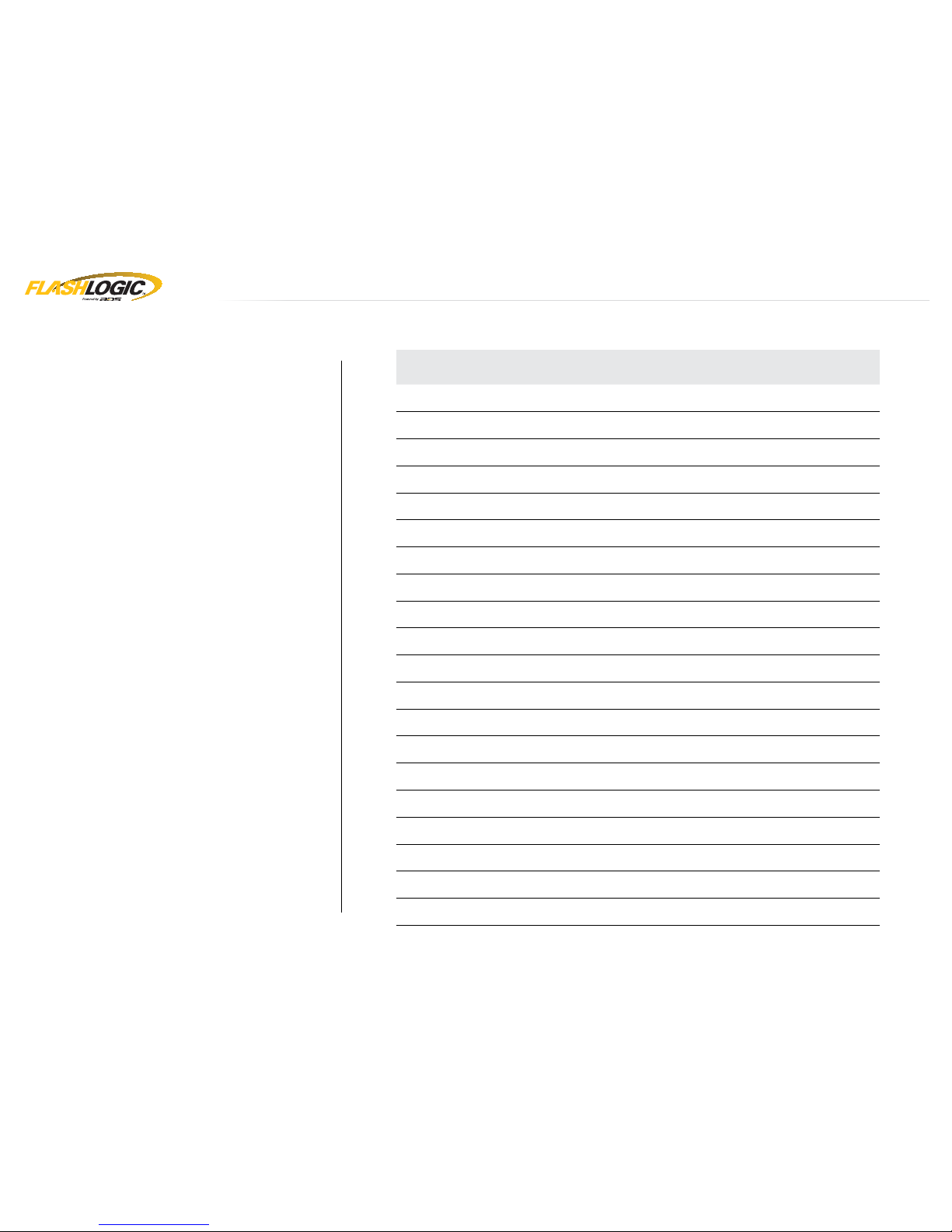
GETTING STARTED - 1 OF 2
TABLE OF CONTENTS
PRESTIGE
Box Contents
4
Compatible Accessories
5-6
Tach Programming Procedure
7
Remote Programming Procedure
8
Valet Mode Programming Procedure
9-13
Online Module Settings
14
Module Diagnostics
15
Remote Starter Error Codes
16
Module Reset Procedure
17
PURSUIT
Box Contents
18
Compatible Accessories
19-20
Tach Programming Procedure
21
Remote Programming Procedure
22
Valet Mode Programming Procedure
23-27
Online Module Settings
28
Module Diagnostics
29
Remote Starter Error Codes
30
Module Reset Procedure
31
WELCOME
Congratulations on the purchase of your FLRSBA
solution. You are now a few simple steps away
from enjoying your new remote starter unit with
enhanced features.
Before starting your installation, please ensure
that your FLRSBA module is programmed with
the correct fi rmware for your vehicle and that you
carefully review the install guide.
www.idatalink.comAutomotive Data Solutions Inc. © 2017 FLRSBA
PAGE 2 OF 52
• 20171103
U.S. Patent No. 8,856,780
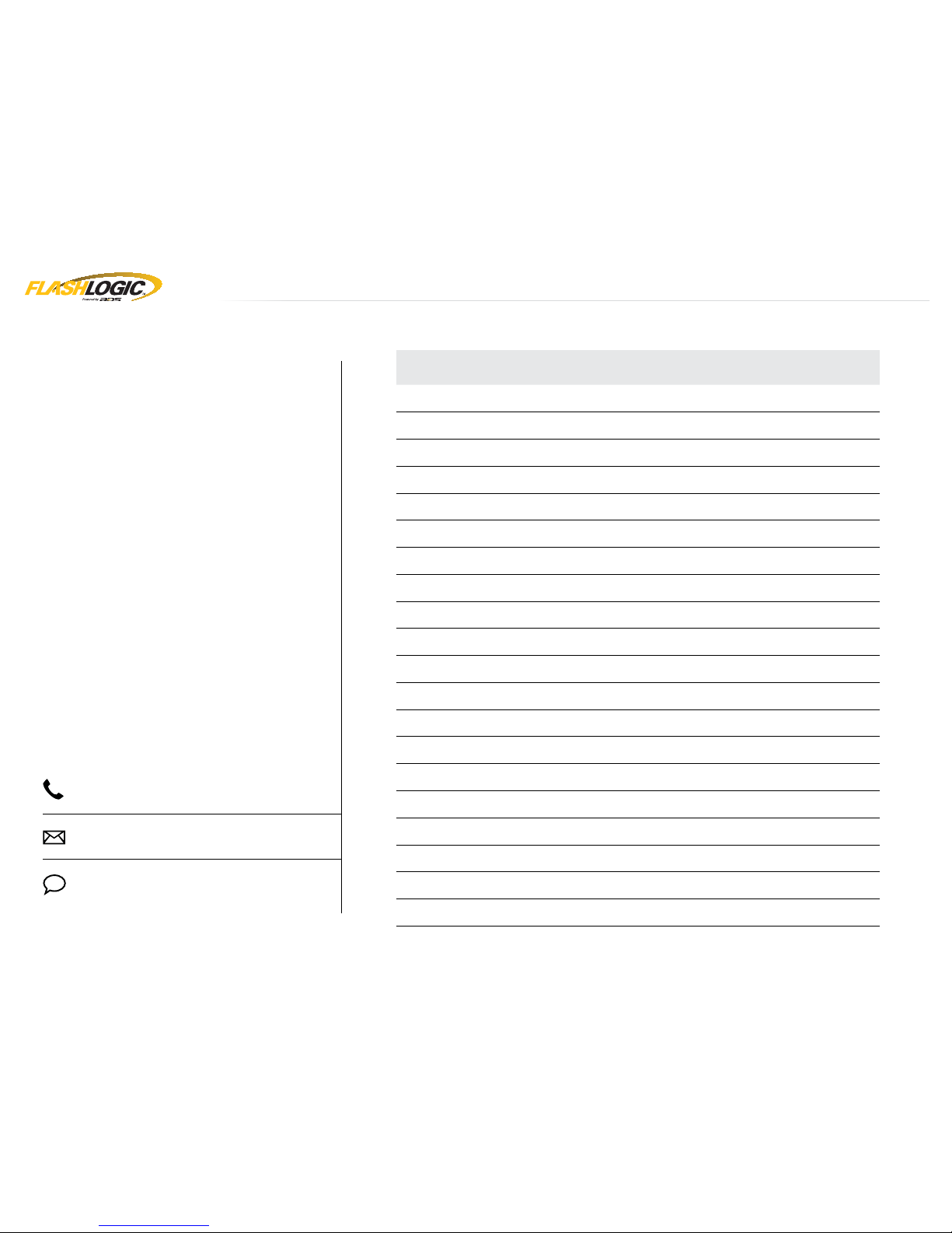
GETTING STARTED - 2 OF 2
TABLE OF CONTENTS
CODE ALARM
Box Contents
32
Compatible Accessories
33-34
Tach Programming Procedure
35
Remote Programming Procedure
36
Valet Mode Programming Procedure
37-38
Online Module Settings
39
Module Diagnostics
40
Remote Starter Error Codes
41
Module Reset Procedure
42
DIRECTED
Box Contents
43
Compatible Accessories
44-45
Tach Programming Procedure
46
Remote Programming Procedure
47
Valet Mode Programming Procedure
48
Online Module Settings
49
Module Diagnostics
50
Remote Starter Error Codes
51
Module Reset Procedure
52
NEED HELP?
1 800 225-6074
www.voxxelectronics.com/care/?p=contactus
www.fl ashlogic.com/support
www.facebook.com/audiovox
www.idatalink.comAutomotive Data Solutions Inc. © 2017 FLRSBA
PAGE 3 OF 52
• 20171103
U.S. Patent No. 8,856,780 PRESTIGE
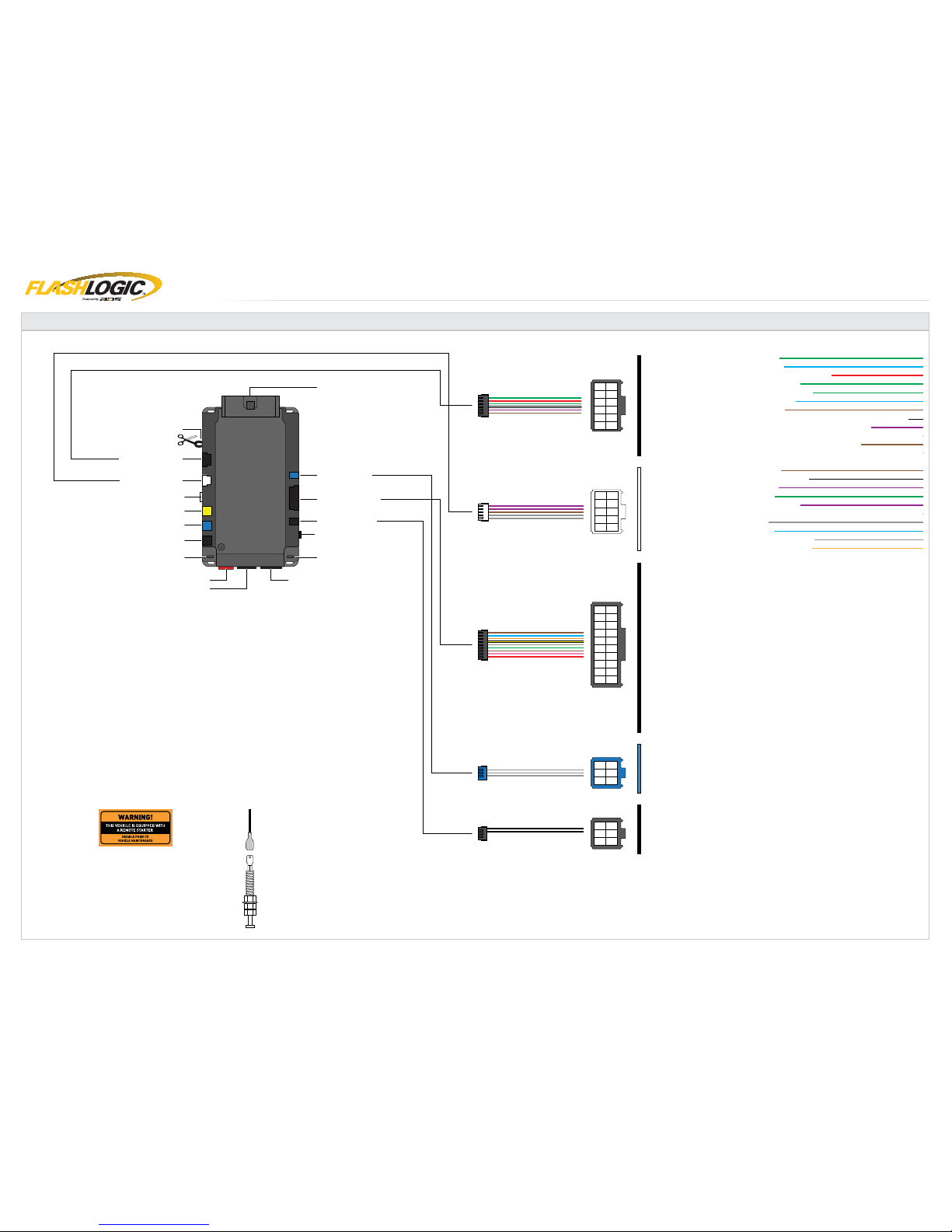
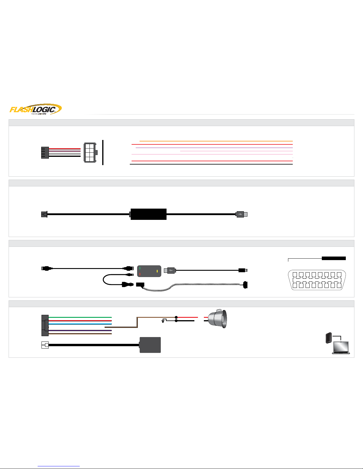
BOX CONTENTS
M9 - 4 PIN RED
M11 - 4 PIN BLUE
PROGRAMMING BUTTON
M7 - 6 PIN BLACK
LED 1
LED 2
M10 - 4 PIN BLACK
M12 - 4 PIN YELLOW
M13 - 4 PIN WHITE
M8 - 5 PIN BLACK
HOOD SWITCH
STICKERS
MODULE
7
9
3
10
8
6
4
1
2
5
7
9
3
10
8
11
12
6
4
1
2
5
7
9
3
10
8
11
13
14
12
15
17
18
19
20
16
6
4
1
2
5
4
5
3
2
1
6
M5
M4
01 GREEN•BLACK DOT - LOCK (-) OUTPUT
01 GREEN•BLACK DOT - LOCK (-) OUTPUT
02 BLUE•BLACK DOT - UNLOCK (-) OUTPUT
02 BLUE•BLACK DOT - UNLOCK (-) OUTPUT
03 RED/WHITE•BLACK DOT - TRUNK RELEASE (-) OUTPUT
03 RED/WHITE•BLACK DOT - TRUNK RELEASE (-) OUTPUT
04 GREEN/WHITE•BLACK DOT - ARM (-) OUTPUT
04 GREEN/WHITE•BLACK DOT - ARM (-) OUTPUT
05 GREEN/BLACK•BLACK DOT - DISARM (-) OUTPUT
05 GREEN/BLACK•BLACK DOT - DISARM (-) OUTPUT
06 BLUE/WHITE•BLACK DOT - GWR (-) OUTPUT
06 BLUE/WHITE•BLACK DOT - GWR (-) OUTPUT
07 BROWN•BLACK DOT - SIREN (+) OUTPUT
07 BROWN•BLACK DOT - SIREN (+) OUTPUT
08 WHITE/PURPLE•BLACK DOT - POC 1 - 2ND UNLOCK OTHER DOORS (-) OUTPUT
08 WHITE/PURPLE•BLACK DOT - POC 1 - 2ND UNLOCK OTHER DOORS (-) OUTPUT
09 PURPLE/BLACK•BLACK DOT - POC 2 - RAP SHUTDOWN (-) OUTPUT
09 PURPLE/BLACK•BLACK DOT - POC 2 - RAP SHUTDOWN (-) OUTPUT
10 WHITE/BLACK•BLACK DOT - POC 3 - HORN (-) OUTPUT
10 WHITE/BLACK•BLACK DOT - POC 3 - HORN (-) OUTPUT
11 BROWN/BLACK•BLACK DOT - POC 4 - STARTER KILL (-) OUTPUT
11 BROWN/BLACK•BLACK DOT - POC 4 - STARTER KILL (-) OUTPUT
12 WHITE•BLACK DOT - PARKING LIGHTS (-) OUTPUT
01 BROWN•SILVER DOT - BRAKE (+) INPUT
02 BLACK/WHITE•SILVER DOT - E-BRAKE (-) INPUT
03 PURPLE•SILVER DOT - DOOR (+) INPUT
04 GREEN•SILVER DOT - DOOR (-) INPUT
05 PURPLE/WHITE•SILVER DOT - TACH (-) INPUT
06 WHITE/BLUE•SILVER DOT - X-TRIGGER (-) INPUT
07 GRAY•SILVER DOT - HOOD (-) INPUT
08 BLUE•SILVER DOT - TRUNK (-) INPUT
09 GRAY/BLACK•SILVER DOT - GLOW PLUG (+) INPUT
10 TAN•SILVER DOT - EXT ALARM SENSOR (-) INPUT
FUNCTIONS DEFINED BY FIRMWARE
FUNCTIONS DEFINED BY FIRMWARE
M3
M2
4
5
3
2
1
6
M6
FUNCTIONS DEFINED BY FIRMWARE
M3 - 10 PIN WHITE
M2 - 12 PIN BLACK
M5 - 6 PIN BLUE
M4 - 20 PIN BLACK
M1 - 8 PIN BLACK
2X
BOX CONTENTS - 1 OF 1
M6 - 6 PIN BLACK
AUTOMATIC
TRANSMISSION
CUT LOOP
www.idatalink.comAutomotive Data Solutions Inc. © 2017 FLRSBA
PAGE 4 OF 52
• 20171103
U.S. Patent No. 8,856,780 PRESTIGE
COMPATIBLE ACCESSORIES - 1 OF 2
4
2
8
1
3
576
M1
MODULE
M1
01 ORANGE - ACCESSORY (+)
01 ORANGE - ACCESSORY (+)
02 RED - POWER (30A)
02 RED - POWER (30A)
03 PURPLE - STARTER (+)
03 PURPLE - STARTER (+)
04 PINK/WHITE - PROG. RELAY #4 - IGNITION 2 (+) (DEFAULT)
04 PINK/WHITE - PROG. RELAY #4 - IGNITION 2 (+) (DEFAULT)
05 PINK - IGNITION (+)
05 PINK - IGNITION (+)
07 RED - POWER (30A)
07 RED - POWER (30A)
08 BLACK - GROUND
08 BLACK - GROUND
06 WHITE - PROG. RELAY #5 (10A) - PARKING LIGHTS (+) (DEFAULT)
06 WHITE - PROG. RELAY #5 (10A) - PARKING LIGHTS (+) (DEFAULT)
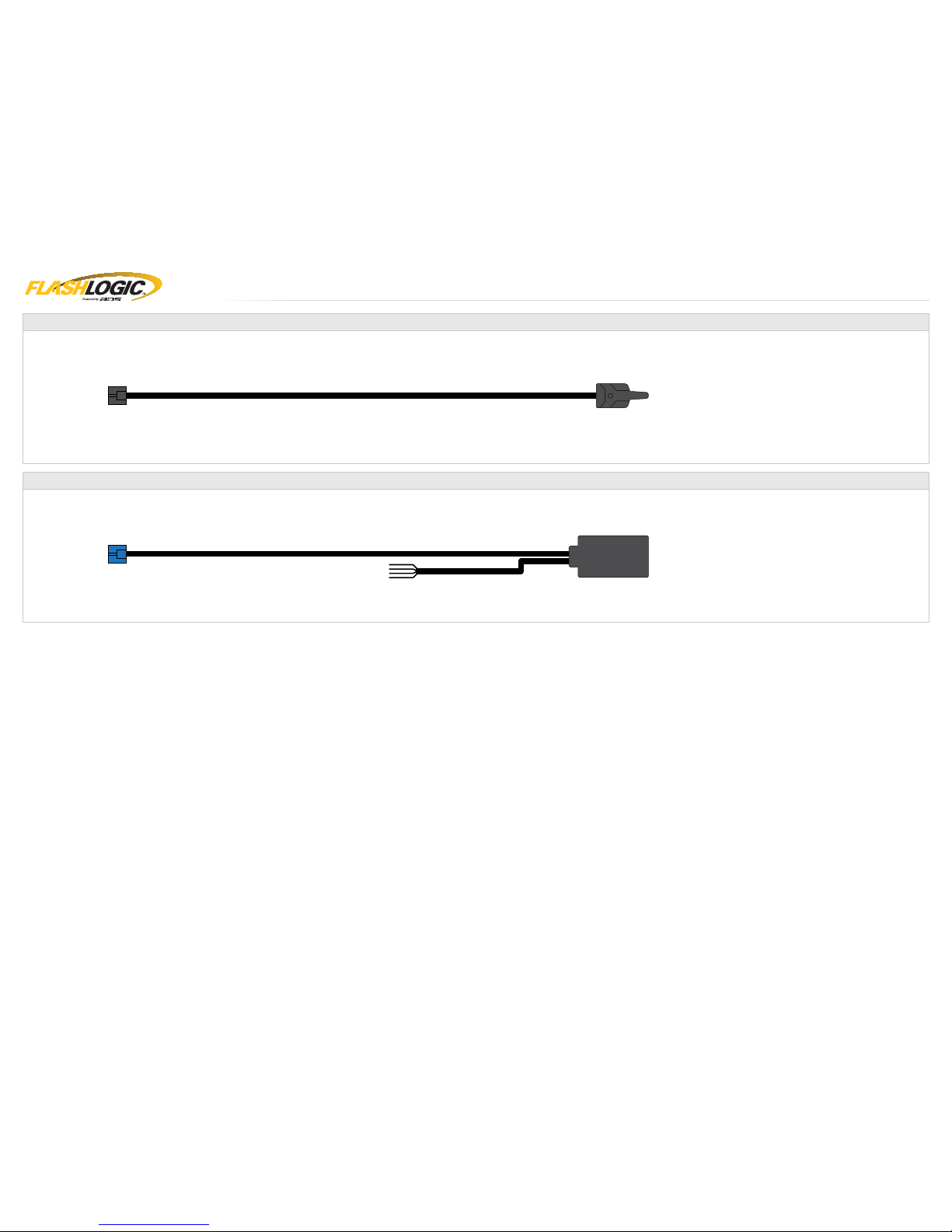
FLASHLOGIC: ADSAHRPWR HIGH CURRENT HARNESS SOLD SEPARATELY
FLASHLOGIC: FLPROG WEBLINK CABLE SOLD SEPARATELY
COMPUTER
USB PORT
4 PIN BLACK CABLE
MODULE
M10
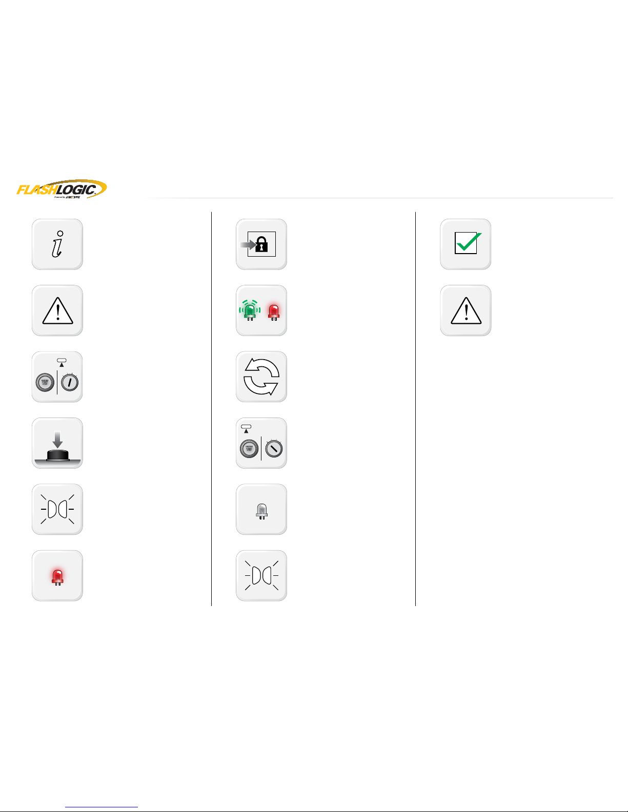
10 11 12 13 14 15 16
1 2 3 4 5 6 7 8
9
MOBILE DEVICE
PORT
OBDII CONNECTOR
4 PIN BLACK CABLE
MODULE
M10
OBDII CONNECTOR
FLASHLOGIC: FLWLMAN1, FLWLMAP1 WEBLINK MOBILE SOLD SEPARATELY
TO ACTIVATE THE BUILT-IN TILT & SHOCK SENSOR,
THE SHOCK SENSOR PORT FOR COMPATIBLE ACCESSORIES AND THE SIREN OUTPUT:
1-LOG INTO YOUR WEBLINK ACCOUNT.
2-CONNECT YOUR CONTROL MODULE AND FOLLOW THE PROGRAMMING STEPS.
3-SELECT BASEC AND ENTER THE 16 DIGIT ACTIVATION CODE.
4-PROCEED WITH THE PROGRAMMING STEPS AND INSTALLATION.
: DIGITAL TILT SENSOR
: GLASS BREAK SENSOR
: FIELD DISTURBANCE/MOVEMENT SENSOR
: DUAL STAGE PIEZO SHOCK SENSOR
: DUAL STAGE INFRASONIC SHOCK SENSOR
DUB1: DIGITAL TILT SENSOR
CAGBS: GLASS BREAK SENSOR
MV3: FIELD DISTURBANCE/MOVEMENT SENSOR
AS9492A: DUAL STAGE PIEZO SHOCK SENSOR
AS94954P: DUAL STAGE INFRASONIC SHOCK SENSOR
FLASHLOGIC: BASEC / VOXX: DUB1, CAGBS, MV3, AS9492A, AS94954P SECURITY PACKAGE SOLD SEPARATELY
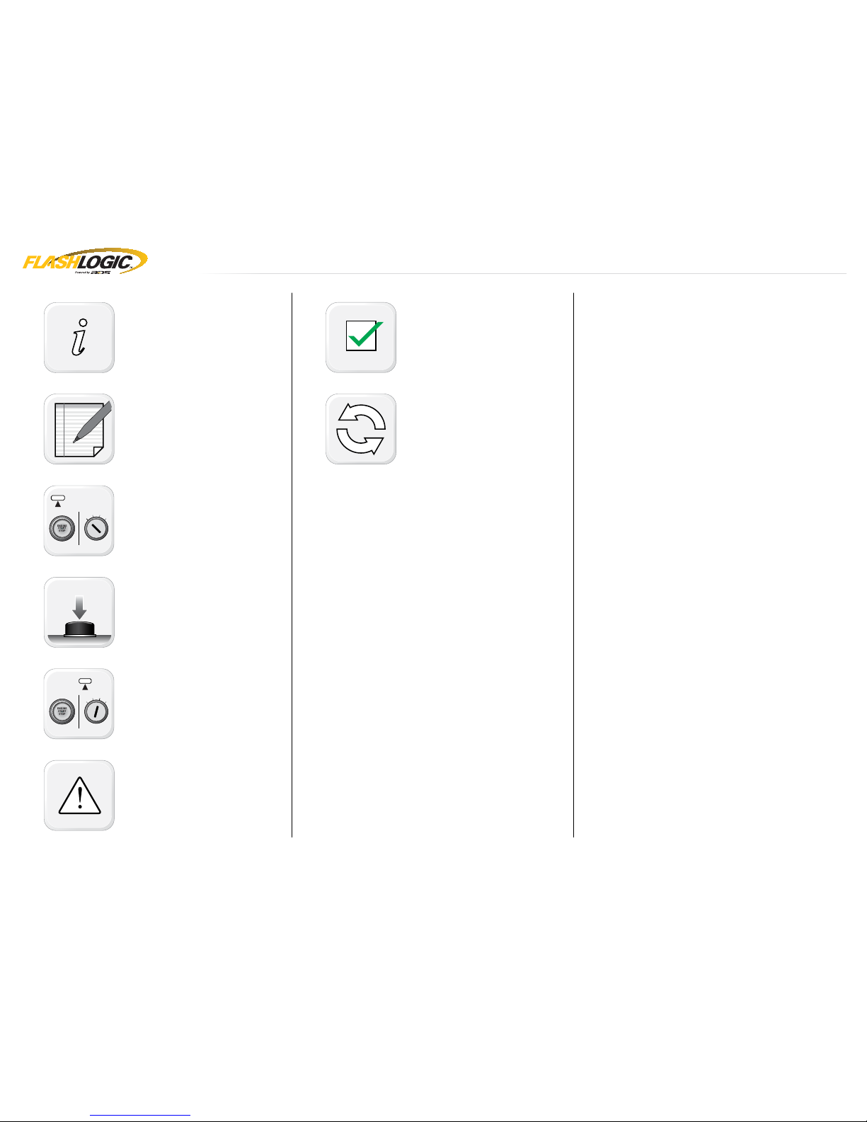
07 BROWN•BLACK DOT - SIREN (+) OUTPUT
RED
BLACK
BASEC SIREN
MODULE
M2
MODULE
M13
OPTIONAL SENSORS
www.idatalink.comAutomotive Data Solutions Inc. © 2017 FLRSBA
PAGE 5 OF 52
• 20171103
U.S. Patent No. 8,856,780 PRESTIGE
COMPATIBLE ACCESSORIES - 2 OF 2
ANTENNA
MODULE
M7
PRESTIGE: PE1B, PE1BTW, PE2LED, PE2LCD, PE5B RF KIT SOLD SEPARATELY
(NC)
MODULE
M11
CARLINK: ASCL6, ASCLBTLR TELEMATIC KIT SOLD SEPARATELY
www.idatalink.comAutomotive Data Solutions Inc. © 2017 FLRSBA
PAGE 6 OF 52
• 20171103

U.S. Patent No. 8,856,780 PRESTIGE
01
ENGINE
START
STOP
OFF ACC ON STARTSTART
START
02
03
04
05
06
TACH PROGRAMMING PROCEDURE - 1 OF 1
START vehicle for 15 seconds.
Press and hold the brake pedal.
Press and release the module’s programming
button. (OR if the remotes are already
programmed to the vehicle, press and hold the
start button of the remote for 2.5 seconds.)
Wait, LED 2 will fl ash GREEN. (See the Module
Diagnostics page)
Release the brake pedal.
Module Programming Procedure completed.
www.idatalink.comAutomotive Data Solutions Inc. © 2017 FLRSBA
PAGE 7 OF 52
• 20171103
U.S. Patent No. 8,856,780 PRESTIGE
>>
>>
01
ENGINE
START
STOP
OFF ACC ON START
ON
02
03
04
05
06
07
08
ENGINE
START
STOP
OFF ACC ON STARTOFF
09
10
11
>>
TYPE 1 - REMOTE PROGRAMMING - 1 OF 1
The following procedure is valid for PRESTIGE
and PURSUIT RF kits. It programs aftermarket
remotes to the remote starter.
WARNING: Program aftermarket remotes
before usage. A maximum of four [4x]
aftermarket remotes per system.
Set ignition to ON position.
Press and release the antenna button three
times [3x].
The parking lights will fl ash once [1x], the
horn will chirp once [1x].
The remote starter LED will turn RED and the
antenna LED will fl ash.
Press once [1x] on LOCK button of aftermarket
remote.
The remote starter LED will fl ash GREEN once
[1x] then will turn RED.
To program additional remotes: repeat steps 5
to 6 using each additional remote.
Set ignition to OFF position.
The remote starter LED will turn OFF and the
antenna LED will turn OFF.
The parking lights will fl ash twice [2x], the
horn will chirp twice [2x].
Remote Programming completed.
TO DELETE ALL REMOTES: repeat steps 1 to
4 then press and hold the antenna button for
6 seconds. The parking lights will fl ash twice
[2x], the horn will chirp twice [2x].
www.idatalink.comAutomotive Data Solutions Inc. © 2017 FLRSBA
PAGE 8 OF 52
• 20171103
U.S. Patent No. 8,856,780 PRESTIGE
>>
01
02
ENGINE
START
STOP
OFF ACC ON STARTOFF
03
04
ENGINE
START
STOP
OFF ACC ON START
ON
05
06
07
TYPE 1 - VALET MODE - 1 OF 1
The following procedure is valid for PRESTIGE
and PURSUIT RF kits. It triggers the Valet
Mode for remote start only.
NOTE: In Valet Mode, the Remote starter is not
functional. Keyless entry, Lock and Unlock will
remain functional.
Set ignition to OFF position.
Press and hold the antenna button.
Cycle ignition ON three times [3x ON/OFF]
rapidly.
The parking lights will fl ash once [1x], the
horn will chirp once [1x], the antenna LED will
fl ash twice [2x] rapidly then once [1x].
Valet Mode completed.
To exit valet mode, repeat steps 2 to 4. The
parking lights will fl ash twice [2x], the horn
will chirp twice [2x], the antenna LED will turn
OFF.
www.idatalink.comAutomotive Data Solutions Inc. © 2017 FLRSBA
PAGE 9 OF 52
• 20171103
U.S. Patent No. 8,856,780 PRESTIGE
>>
01
02
ENGINE
START
STOP
OFF ACC ON START
ON
03
04
05
ENGINE
START
STOP
OFF ACC ON STARTOFF
06
07
TYPE 2 - VALET MODE - 1 OF 1
The following procedure is valid for PRESTIGE
and PURSUIT RF kits. It triggers the Valet
Mode for alarm only.
NOTE: In Valet Mode, the alarm is disabled
and the Remote starter is functional. Keyless
entry, Lock and Unlock will remain functional.
Set ignition to ON position.
Press and hold the antenna button for 5
seconds.
The parking lights will fl ash once [1x], the
horn will chirp once [1x], the antenna LED will
turn ON.
Set ignition to OFF position.
Valet Mode completed.
To exit valet mode, repeat steps 2 to 3. The
parking lights will fl ash twice [2x], the horn
will chirp twice [2x], the antenna LED will turn
OFF.
www.idatalink.comAutomotive Data Solutions Inc. © 2017 FLRSBA
PAGE 10 OF 52
• 20171103
U.S. Patent No. 8,856,780 PRESTIGE
>>
01
02
ENGINE
START
STOP
OFF ACC ON START
ON
03
04
05
ENGINE
START
STOP
OFF ACC ON STARTOFF
06
07
TYPE 3 - VALET MODE - 1 OF 1
The following procedure is valid for PRESTIGE
and PURSUIT RF kits. It triggers the Valet
Mode for remote start and alarm if the alarm
override option is set to valet switch (Menu 3,
Option 22).
NOTE: In Valet Mode, the Remote starter is not
functional. Keyless entry, Lock and Unlock will
remain functional.
Cycle ignition ON twice [2x OFF/ON] rapidly.
Press and release the BRAKE pedal three
times [3x].
The parking lights will fl ash once [1x], the
horn will chirp once [1x], the antenna LED will
turn ON.
Set ignition to OFF position.
Valet Mode completed.
To exit valet mode, repeat steps 2 to 3. The
parking lights will fl ash twice [2x], the horn
will chirp twice [2x], the antenna LED will turn
OFF.
www.idatalink.comAutomotive Data Solutions Inc. © 2017 FLRSBA
PAGE 11 OF 52
• 20171103

U.S. Patent No. 8,856,780 PRESTIGE
>>
01
02
ENGINE
START
STOP
OFF ACC ON START
ON
03
04
ENGINE
START
STOP
OFF ACC ON START
ON
05
06
ENGINE
START
STOP
OFF ACC ON START
ON
07
ENGINE
START
STOP
OFF ACC ON STARTSTART
START
08
ENGINE
START
STOP
OFF ACC ON STARTOFF
09
TYPE 4 - VALET MODE - 1 OF 1
The following procedure is valid for PRESTIGE
and PURSUIT RF kits. It triggers the Valet
Mode with a custom code override. The default
override code is 11.
NOTE: In Valet Mode, the Remote starter is not
functional. Keyless entry, Lock and Unlock will
remain functional.
Set ignition to ON position.
Press the antenna programming button once
[1x].
Cycle ignition ON once [1x OFF/ON] rapidly.
Press the antenna programming button once
[1x].
Cycle ignition ON once [1x ON/OFF] rapidly.
Set ignition to START position. (Engine
running.)
Set ignition to OFF position.
Valet Mode completed.
www.idatalink.comAutomotive Data Solutions Inc. © 2017 FLRSBA
PAGE 12 OF 52
• 20171103
U.S. Patent No. 8,856,780 PRESTIGE
>>
01
02
ENGINE
START
STOP
OFF ACC ON START
ON
03
04
05
ENGINE
START
STOP
OFF ACC ON START
ON
06
07
ENGINE
START
STOP
OFF ACC ON START
ON
08
09
ENGINE
START
STOP
OFF ACC ON STARTOFF
10
11
TYPE 5 - VALET MODE - 1 OF 1
The following procedure is valid for PRESTIGE
and PURSUIT RF kits. It sets a new custom
code override to trigger the Valet Mode.
Press once [1x] on the unlock button of the
aftermarket remote.
Set ignition to ON position.
TIME RESTRICTION. Complete steps 4 to 9
within 45 seconds.
Press the antenna programming button three
times [3x].
Cycle ignition ON three times [3x OFF/ON]
rapidly.
Press the antenna programming button up
to 9 times, to set the tenths digit from 1 to 9.
Each button press increments the digit by one.
Cycle ignition ON once [1x OFF/ON] rapidly.
Press the antenna programming button up
to 9 times, to set the tenths digit from 1 to 9.
Each button press increments the digit by one.
Set ignition to OFF position.
LED will fl ash as many times as the tenths
digit, then will fl ash as many times as the
units digit.
Valet Mode completed.
www.idatalink.comAutomotive Data Solutions Inc. © 2017 FLRSBA
PAGE 13 OF 52
• 20171103

U.S. Patent No. 8,856,780 PRESTIGE
ONLINE MODULE SETTINGS - 1 OF 1
WEB PROGRAMMABLE MENUS DESCRIPTION
MENU 1 – Remote Starter RS related confi guration options
MENU 2 – Doorlock Options Convenience feature confi guration options
MENU 3 – Security Options Alarm activation and settings
MENU 4 – AUX function assignments Set transmitter AUX buttons controls
MENU 5 – Programmable outputs (POC) Set actions for programmable outputs
MENU 6 – Pulse Timer Output Confi guration (PTO) Set duration for pulse timer outputs (if used)
MENU 7 – Input Confi gurations Set inputs for Auto by fi rmware/Data/Analog
MENU 8 – Output Confi gurations Set outputs for Auto by fi rmware/Data/Analog
Programming options are avaible through Weblink and Weblink Mobile only.
www.idatalink.comAutomotive Data Solutions Inc. © 2017 FLRSBA
PAGE 14 OF 52
• 20171103

U.S. Patent No. 8,856,780 PRESTIGE
MODULE DIAGNOSTICS - 1 OF 1
TEST MODULE
LED 1 STATUS
DIAGNOSTIC
I DURING MODULE PROGRAMMING
Flashing RED Missing/wrong information from fi rmware or vehicle.
Solid RED Module waiting for more vehicle information.
Flashing GREEN Additional steps required to complete module programming.
Solid GREEN then OFF Module correctly programmed.
OFF No activity or module already programmed.
II DURING TACH PROGRAMMING
1 GREEN fl ash Tach signal programmed in Analog
2 GREEN fl ashes Tach signal programmed in Data
3 RED fl ashes No tach signal detected
4 RED fl ashes System is in valet mode
5 RED fl ashes Tach set for ‘VTS’. No tach programming required
6 RED fl ashes Tach set for ‘assumed start’. No tach programming required
III DURING REMOTE START
Flashing RED Module incorrectly programmed.
Solid RED Module incorrectly programmed.
Flashing GREEN Module correctly programmed and operational.
Solid GREEN then OFF Reset in progress.
OFF Invalid ground when running status from remote starter.
IV WITH IGNITION OFF
Flashing RED Module incorrectly programmed or connected.
Solid RED Module not programmed. Waiting for more vehicle information.
Flashing GREEN False ground when running status from remote starter.
Solid GREEN then OFF Reset in progress.
OFF Module at rest and ready for a remote start sequence.
www.idatalink.comAutomotive Data Solutions Inc. © 2017 FLRSBA
PAGE 15 OF 52
• 20171103

U.S. Patent No. 8,856,780 PRESTIGE
REMOTE STARTER ERROR CODES - 1 OF 1
REMOTE STARTER ERROR CODES:
NOTES
[X] NUMBER OF
PARKING LIGHT
FLASHES
DIAGNOSTIC
I WARNING: The following applies only when the parking
lights are connected and supported by the system.
01 Engine running.
02 Key in ignition at ON position.
II After a remote starter failure, the parking lights will fl ash
three [3x] times, then will fl ash [X] number times to
indicate an error code. See table.
03 Door is open.
04 Trunk is open.
05 Foot brake is ON.
06 Hood is open.
07 The reservation is OFF. (Manual transmission only)
08 Tach failure.
09 The vehicle is moving (VSS).
10 System is in Valet Mode.
11 CAN communication failure
12 RS not synchronized. Start vehicle with OEM key for 15 sec before trying a new RS sequence.
13 Bypass problem.
REMOTE STARTER SHUTDOWN ERROR CODES:
NOTES
[Y] NUMBER OF
PARKING LIGHT
FLASHES
DIAGNOSTIC
I WARNING: The following applies only when the parking
lights are connected and supported by the system.
01 Engine tach signal is lost.
02 Emergency brake is lost.
II
If the engine shuts down after a remote starter sequence:
Press and hold the Trunk button and the Start button at the
same time for 2.5 seconds when using a 1-WAY remote.
OR
Press once [1x] on button “4” when using a 2-WAY remote.
The parking lights will fl ash four [4x] times, then will fl ash
[Y] number times to indicate an error code. See table.
03 Foot brake is ON.
04 Hood is open.
05 Engine RPM limiter is ON.
06 Glow plug timeout error.
07 Vehicle is moving (VSS).
08 N/A
09 N/A
10 Door is open.
11 CAN communication failure during RS sequence.
12 RS not synchronized. Start vehicle with OEM key for 15 sec before trying a new RS sequence.
13 Takeover is not allowed.
14 Shutdown error, board overheat protection.
www.idatalink.comAutomotive Data Solutions Inc. © 2017 FLRSBA
PAGE 16 OF 52
• 20171103
 Loading...