

Page 1
!
Automotive Data Solutions Inc.
INSTALL GUIDE
GM2
FLC-AL(DL)-GM2-EN
AVAILABLE FOR : FLCAN
Rev. Date: May 31, 2017
Doc. No.: ##39835##
U.S. PATENT NO. 8,856,780
PLEASE VISIT WWW.FLASHLOGIC.COM FOR COMPLETE PRODUCT DETAILS
The brand names and logos found in this guide are property of their respective owners. Automotive Data Solutions Inc. © 2017
NOTICE: The manufacturer will accept no responsibility for any electrical damage resulting from
improper installation of this product, be that either damage to the vehicle itself or to the installed
device. This device must be installed by a certified technician. This guide has been written for
properly trained technicians; a certain level of skill & knowledge is therefore assumed. Please
review the Installation Guide carefully before beginning any work.
Page 2
XX-XX PAGE X-X
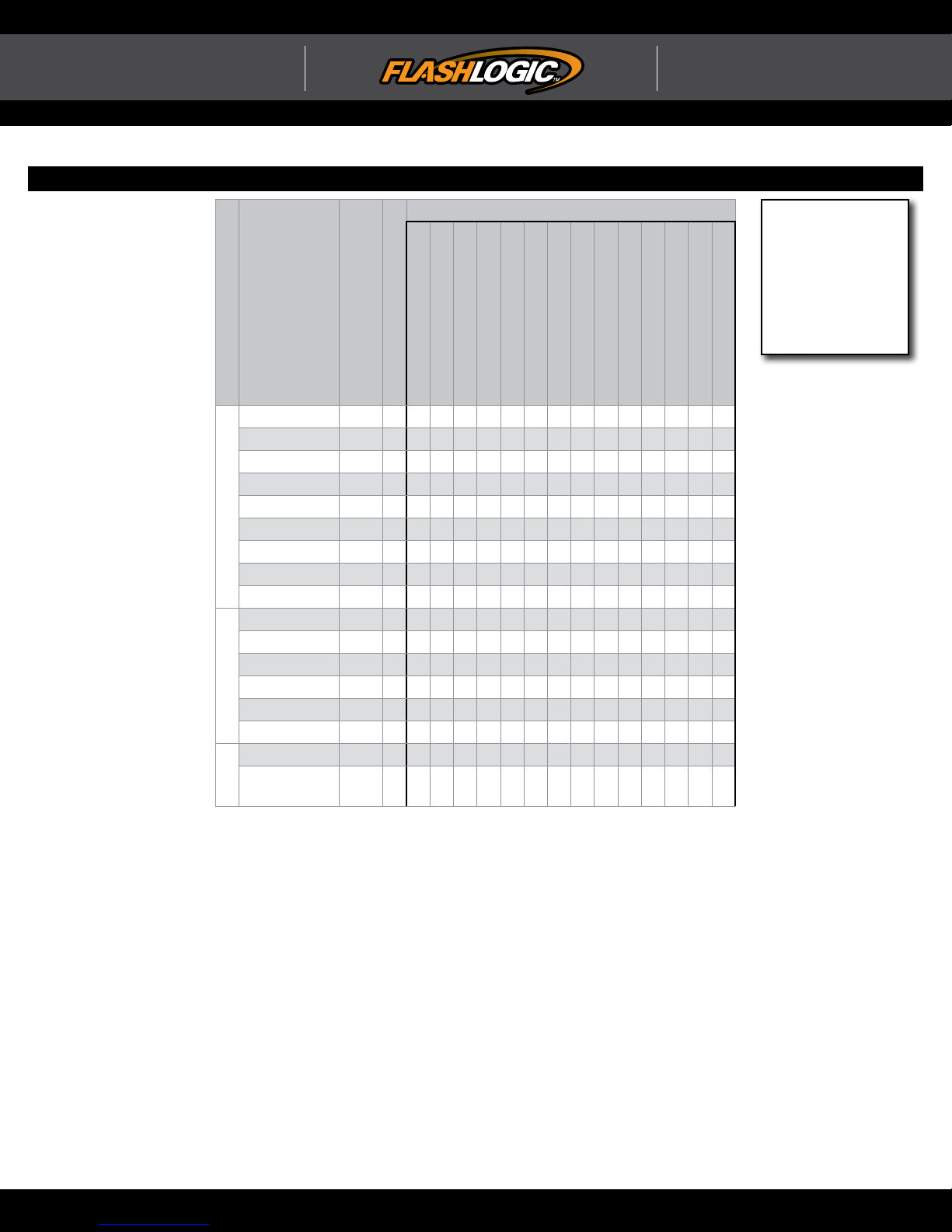
INSTALL TYPE SELECTION
ADS-AL(DL)-GM2 PAGE 2-3
INSTALL GUIDE
U.S. Patent No. 8,856,780
ALL IN ONE
General Motors
Page 2 of 11 FLC-AL(DL)-GM2-EN 20170531
Doc. No.: ##39835##
FEATURES
3
1
MAKE
Cobalt 05-06 1 • • • • • • • • • • • •
Cobalt 07-10 2 • • • • • • • • • • • • • •
HHR 06 1 • • • • • • • • • • •
HHR 07-11 2 • • • • • • • • • • • • •
Malibu Classic 04-07 1 • • • • • • • • • • • •
Malibu 07-12 2 • • • • • • • • • • • • • •
CHEVROLET
Malibu Hybrid 08-12 2 • • • • • • • • • • • • • •
Malibu MAXX 04-06 1 • • • • • • • • • • • •
Malibu MAXX 07-09 2 • • • • • • • • • • • • • •
G6 05-06 1 • • • • • • • • • • • •
G6 07-09 2 • • • • • • • • • • • • • •
Pursuit / G5 05-06 1 • • • • • • • • • • • •
Pursuit / G5 07-10 2 • • • • • • • • • • • • • •
PONTIAC
Solstice 06 1 • • • • • • • • • • • •
Solstice 07-09 2 • • • • • • • • • • • • • •
Aura / Hybrid 07-10 2 • • • • • • • • • • • • • •
MODEL
YEAR
INSTALL TYPE
DATA IMMOBILIZER BYPASS
ARM OEM ALARM
DISARM OEM ALARM
DOOR LOCK1DOOR UNLOCK1PRIORITY UNLOCK1TRUNK/HATCH RELEASE
PUDDLE LIGHT CTRL2DOOR STAT OUTPUT
TRUNK STAT OUTPUT
TACHOMETER OUTPUT
BRAKE PEDAL STAT OUTPUT
3
E-BRAKE OUTPUT
NOTE
I The 10th character
in the Vehicle Identifi cation Number
(VIN) indicates
the manufacturing year: 1=2001;
2=2002; 3=2003...
RAP SHUTDOWN CTRL
Sky 07-09 2 • • • • • • • • • • • • • •
SATURN
1
Doorlocks and trunk release features on the module will not operate on vehicles that are not
equipped with OEM keyless entry.
2 If puddle light function is active in vehicle settings.
3
Available on AL-CA modules in DATA and STANDARD mode.
Available on DL modules in DATA mode only.
WWW.FLASHLOGIC.COM Automotive Data Solutions Inc. © 2017
Page 3
XX-XX PAGE X-XADS-AL(DL)-GM2 PAGE X-X
INSTALL GUIDE
U.S. Patent No. 8,856,780
ALL IN ONE
General Motors
Page 3 of 11 FLC-AL(DL)-GM2-EN 20170531
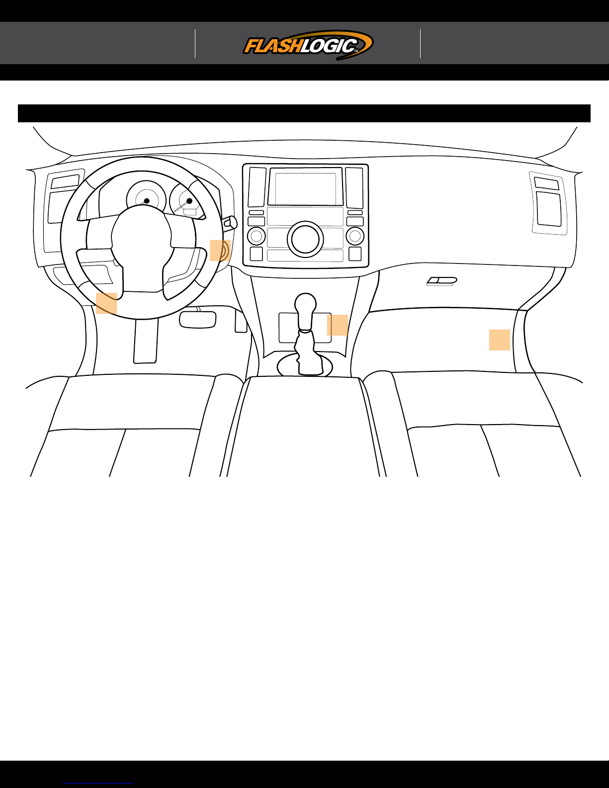
COMPONENT LOCATOR
Doc. No.: ##39835##
A
D
B
C
WWW.FLASHLOGIC.COM Automotive Data Solutions Inc. © 2017
Page 4

XX-XX PAGE X-X
ADS-AL(DL)-GM2 PAGE 1-2
ALL IN ONE
INSTALL GUIDE
U.S. Patent No. 8,856,780
General Motors
Page 4 of 11 FLC-AL(DL)-GM2-EN 20170531
Doc. No.: ##39835##
KNOWLEDGE BASE
HOW TO TEST THE “NEW GENERATION PASSLOCK” WIRE
The Passlock wire’s voltage can vary according to the ignition’s position. Although a small variation can occur when using a voltmeter, the Passlock wire should
refl ect the following results:
• On “Key sense”, the wire tests ±12 VDC
• On “Accessory”, the wire tests ±0 VDC
• With the ignition “ON”, the wire tests ±4.0 VDC
• Upon start, the wire tests ±3 VDC
When learning the module to the vehicle, consider the module have to read 20 identical voltage values on every key position before validating all the Passlock
values. Give the module enough time into every key position to acquire its accurate sampling (follow the module LED reactions as found in the programming
procedure).
WARNING!
The vehicles equipped with a new generation Passlock system usually don’t have any (+) Start wire. The vehicle monitors the Passlock wire and the Accessory
Power Drop while the ignition is ON to determine proper crank timing. Do not connect the remote starter (+) start wire to the vehicle.
ADVANCED DIAGNOSTIC (Available only on 32K, 64K and 128K microcontrollers)
Did you know the module will display its confi guration information in the vehicle info center found in the instrument panel cluster or on the radio display.
The module will automatically broadcast the information at the end of its learn sequence. You can also recall the information at any time by turning the key to the
ON position and once the key is turned ON, press and hold down the programming button for 2 seconds and then release it.
The information displayed will be:
• Install Type
• PK3 Detected
• Passlock value at ignition
• Passlock value at start
• Keyless confi guration
• Year matching VIN
• Auto Relock confi guration
“NEW GENERATION” PASSLOCK/PK3+ TAMPER MODE
The new generation Passlock system is equipped with an anti theft countdown. When a failure to provide the vehicle the expected Passlock value, the vehicle
will lock itself in Tamper Mode. Depending on various criteria, the vehicle BCM will evaluate the security breach and will decide if it locks itself in regular or
“bad” Passlock tamper mode or in PK3 tamper mode.
PASSLOCK TAMPER MODE SYMPTOMS
The vehicle starts, ECM shuts off the fuel injectors and the security indicator starts blinking in the instrument panel cluster.
• To exit Passlock Tamper Mode, repair the failure in question.
• During the following steps, make sure the battery is fully charged (it is recommend to apply e-brake to turn off DTRL on Canadian vehicles).
• Turn the vehicle ignition ON, move the key to the START position and bring it back to the ON position before the car started.
• Leave the key to the ON position. The security indicator will start blinking.
• After 10 minutes, the security indicator will stop blinking, turn ON solid, then turn OFF.
• Turn the vehicle ignition to the OFF position, wait 15 seconds and then attempt to start the vehicle.
• If the vehicle starts, wait for the security indicator to turn OFF before you turn off the engine. If the vehicle fails to start, keep the ignition ON, you are in
“BAD” Tamper mode and may have to repeat the entire sequence up to 3 times which may take over 30 minutes. There’s no solution to get the vehicle out of
Tamper Mode faster then waiting the required delays in each cycles.
PK3 TAMPER MODE SYMPTOMS
The vehicle doesn’t start and the info center indicates a PK3+ failure.
• To exit PK3+ Tamper Mode, repair the failure in question.
• Close all vehicle doors
• Wait at least 3 minutes.
• Then start the vehicle using a valid key.
• The vehicle should start.
• If the vehicle refuses to start, unplug the vehicle battery for 30 seconds, then reconnect the battery and start the vehicle again. If the circuitry is properly
connected and a valid key is used, the vehicle will start.
WWW.FLASHLOGIC.COM Automotive Data Solutions Inc. © 2017
Page 5
ADS-AL(DL)-GM2 T1 1-1 PAGE X-X
INSTALL GUIDE
U.S. Patent No. 8,856,780
ALL IN ONE
General Motors
Page 5 of 11 FLC-AL(DL)-GM2-EN 20170531
Doc. No.: ##39835##
TYPE 1 - WIRE CROSS REFERENCE CHART
CONNECTOR
MAKE
MODEL
Cobalt 05-06
HHR 06
CHEVROLET
Malibu Classic
Malibu MAXX
G6 05-06
Pursuit / G5 05-06
PONTIAC
Solstice 06
YEAR
WIRE
DESCRIPTION
Ignition ~ Green 6 pin 3 Pink or Yellow (+) Ignition switch A
Accessory ~ Green 6 pin 4 Brown (+) Ignition switch A
Passlock ~ Green 6 pin 5 White ~ Ignition switch A
12V ~ Green 6 pin 2 Red/White (+) Ignition switch A
12V ~ Black 5 pin 1 Red/White (+) PK3+ A
Data (SWC) OBDII ~ 16 pin 1 Green (DATA) OBDII D
Data (Keyless) C2 White 72 pin 12 Tan/White or LtGreen (D ATA) BCM B
Ignition ~ Green 6 pin 3 Pink or Yellow (+) Ignition switch A
Accessory ~ Green 6 pin 4 Brown (+) Ignition switch A
Passlock ~ Green 6 pin 5 White ~ Ignition switch A
12V ~ Green 6 pin 2 Red/White (+) Ignition switch A
12V ~ Black 5 pin 1 Red/White (+) PK3+ A
Data (SWC) OBDII ~ 16 pin 1 Green (DATA) OBDII D
Data (Keyless) C2 White 72 pin 12 Tan/White or LtGreen (D ATA) BCM B
Ignition ~ Green 6 pin 3 Pink or Yellow (+) Ignition switch A
Accessory ~ Green 6 pin 4 Brown (+) Ignition switch A
Passlock ~ Green 6 pin 5 White ~ Ignition switch A
04-07
12V ~ Green 6 pin 2 Red/White (+) Ignition switch A
04-06
12V ~ Black 5 pin 1 Red/White (+) PK3+ A
Data (SWC) OBDII ~ 16 pin 1 Green (DATA) OBDII D
Data (Keyless) C2 White 72 pin 12 Tan/White or LtGreen (D ATA) BCM B
Ignition ~ Green 6 pin 3 Pink or Yellow (+) Ignition switch A
Accessory ~ Green 6 pin 4 Brown (+) Ignition switch A
Passlock ~ Green 6 pin 5 White ~ Ignition switch A
12V ~ Green 6 pin 2 Red/White (+) Ignition switch A
12V ~ Black 5 pin 1 Red/White (+) PK3+ A
Data (SWC) OBDII ~ 16 pin 1 Green (DATA) OBDII D
Data (Keyless) C2 White 72 pin 12 Tan/White or LtGreen (D ATA) BCM B
Ignition ~ Green 6 pin 3 Pink or Yellow (+) Ignition switch A
Accessory ~ Green 6 pin 4 Brown (+) Ignition switch A
Passlock ~ Green 6 pin 5 White ~ Ignition switch A
12V ~ Green 6 pin 2 Red/White (+) Ignition switch A
12V ~ Black 5 pin 1 Red/White (+) PK3+ A
Data (SWC) OBDII ~ 16 pin 1 Green (DATA) OBDII D
Data (Keyless) C2 White 72 pin 12 Tan/White or LtGreen (D ATA) BCM B
Ignition ~ Green 6 pin 3 Pink or Yellow (+) Ignition switch A
Accessory ~ Green 6 pin 4 Brown (+) Ignition switch A
Passlock ~ Green 6 pin 5 White ~ Ignition switch A
12V ~ Green 6 pin 2 Red/White (+) Ignition switch A
12V ~ Black 5 pin 1 Red/White (+) PK3+ A
Data (SWC) OBDII ~ 16 pin 1 Green (DATA)
Data (Keyless) C2 White 72 pin 12 Tan/White or LtGreen (D ATA) BCM C
NAME
COLOR
TYPE
POSITION
WIRE
COLOR
POLARITY
MODULE
LOCATION
OBDII D
COMPONENT
LOCATOR
WWW.FLASHLOGIC.COM Automotive Data Solutions Inc. © 2017
Page 6
INSTALL GUIDE
ALL IN ONE
General Motors
U.S. Patent No. 8,856,780
Page 6 of 11 FLC-AL(DL)-GM2-EN 20170531
Doc. No.: ##39835##
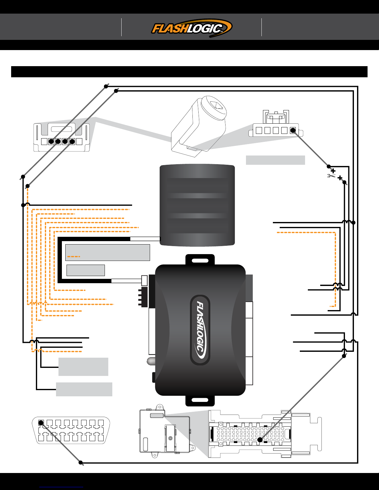
TYPE 1 - WIRING DIAGRAM
ACC (+)
5
12V (+)
4
PASSLOCK
3
2
IGN (+)
123456
IGNITION SWITCH
CONNECTOR - WHITE
IGNITION SWITCH
PK3+
PK3+ CONNECTOR - BLACK
1
12345
12V (+)
IF THERE IS NO PK3+ CONNECTOR
IGNORE RED/WHITE WIRE CUT
REMOTE STARTER
ACCESSORY (+)
ACCESSORY (+)
TACH (AC) INPUT
TRUNK/TAILGATE WINDOW RELEASE (-) OUTPUTTRUNK/TAILGATE WINDOW RELEASE (-) OUTPUT
LEGEND
N/A
NOT REQUIRED IN DATA MODE (1-WAY)
NOT REQUIRED IN DATA MODE (2-WAY)
TACH (AC) INPUT
UNLOCK (-) OUTPUT
UNLOCK (-) OUTPUT
LOCK (-) OUTPUT
LOCK (-) OUTPUT
GROUND (-)
GROUND (-)
GWR (-) OUTPUT
GWR (-) OUTPUT
DATA MODE
<- REQUIRED
<- REQUIRED
<- REQUIRED
<- REQUIRED
<- REQUIRED
<- REQUIRED
<- REQUIRED
REQUIRED ->
OPTIONAL ->
OPTIONAL ->
IGNITION (+) OUTPUT
IGNITION (+) OUTPUT
TRUNK STATUS (-) INPUT
TRUNK STATUS (-) INPUT
DOOR STATUS (-) INPUT
DOOR STATUS (-) INPUT
USE DATA MODE
OR HARDWIRE MODE
DATA MODE
GWR (-) INPUT - BLUE/WHITE
GWR (-) INPUT - BLUE/WHITE
LOCK/ARM (-) INPUT - GREEN/BLACK
LOCK/ARM (-) INPUT - GREEN/BLACK
UNLOCK/DISARM (-) INPUT - BLUE/BLACK
TRUNK/TAILGATE WINDOW RELEASE (-) INPUT - RED/WHITETRUNK/TAILGATE WINDOW RELEASE (-) INPUT - RED/WHITE
OBDII CONNECTOR LOCATED
UNDER DRIVER SIDE DASH
1
UNLOCK/DISARM (-) INPUT - BLUE/BLACK
AUTO-RELOCK (+) INPUT - WHITE
AUTO-RELOCK (+) INPUT - WHITE
ACCESSORY (+) INPUT - BLACK/WHITEACCESSORY (+) INPUT - BLACK/WHITE
RAP SHUTDOWN (-) OUTPUT -
*TACH (AC) OUTPUT - PURPLE/WHITE
*TACH (AC) OUTPUT - PURPLE/WHITE
CONNECT TO DRIVER DOOR
SWITCH TO TURN OFF RADIO
AT THE END OF THE
REMOTE START SEQUENCE
CONNECT TO CONSTANT 12V (+)
TO ENABLE AUTOMATIC RELOCK
AFTER START
DATA (SWC)
(NC) WHITE
(NC) WHITE
GROUND - BLACK
GROUND - BLACK
12V (+) - RED12V (+) - RED
(NC) PURPLE/YELLOW
(NC) PURPLE/YELLOW
(NC) PURPLE/BLACK
(NC) PURPLE/BLACK
87654321
161514131211109
(NC) BROWN(NC) BROWN
GREENRAP SHUTDOWN (-) OUTPUT - GREEN
BCM
WHITE/BLACK - PK3 (+) VEHICLE SIDE
WHITE/BLACK - PK3 (+) VEHICLE SIDE
WHITE/RED - PK3 (+) KEY SIDE
WHITE/RED - PK3 (+) KEY SIDE
WHITE (NC)
WHITE (NC)
YELLOW/BLACK - DOOR STATUS (-) OUTPUT
YELLOW/BLACK - DOOR STATUS (-) OUTPUT
YELLOW/RED - TRUNK STATUS (-) OUTPUT
YELLOW/RED - TRUNK STATUS (-) OUTPUT
YELLOW - PASSLOCK
YELLOW - PASSLOCK
BROWN/RED (NC)
BROWN/RED (NC)
BROWN/YELLOW (NC)
BROWN/YELLOW (NC)
ORANGE/BLACK - DATA (KEYLESS)
ORANGE/BLACK - DATA (KEYLESS)
ORANGE/WHITE (NC)
ORANGE/WHITE (NC)
ORANGE - DATA (SWC)
ORANGE - DATA (SWC)
PINK/BLACK (NC)
PINK/BLACK (NC)
PINK - IGNITION (+) INPUT
PINK - IGNITION (+) INPUT
BLUE/RED (NC)
BLUE/RED (NC)
BLUE/YELLOW (NC)
BLUE/YELLOW (NC)
GREEN/RED (NC)
GREEN/RED (NC)
GREEN/YELLOW (NC)
GREEN/YELLOW (NC)
GRAY/RED (NC)
GRAY/RED (NC)
GRAY/YELLOW (NC)
GRAY/YELLOW (NC)
C2 - WHITE
55
1
12
DATA (KEYLESS)
72
18
WWW.FLASHLOGIC.COM Automotive Data Solutions Inc. © 2017
Page 7
ADS-AL(DL)-GM2 T2 1-2 PAGE X-X
INSTALL GUIDE
U.S. Patent No. 8,856,780
ALL IN ONE
General Motors
Page 7 of 11 FLC-AL(DL)-GM2-EN 20170531
Doc. No.: ##39835##
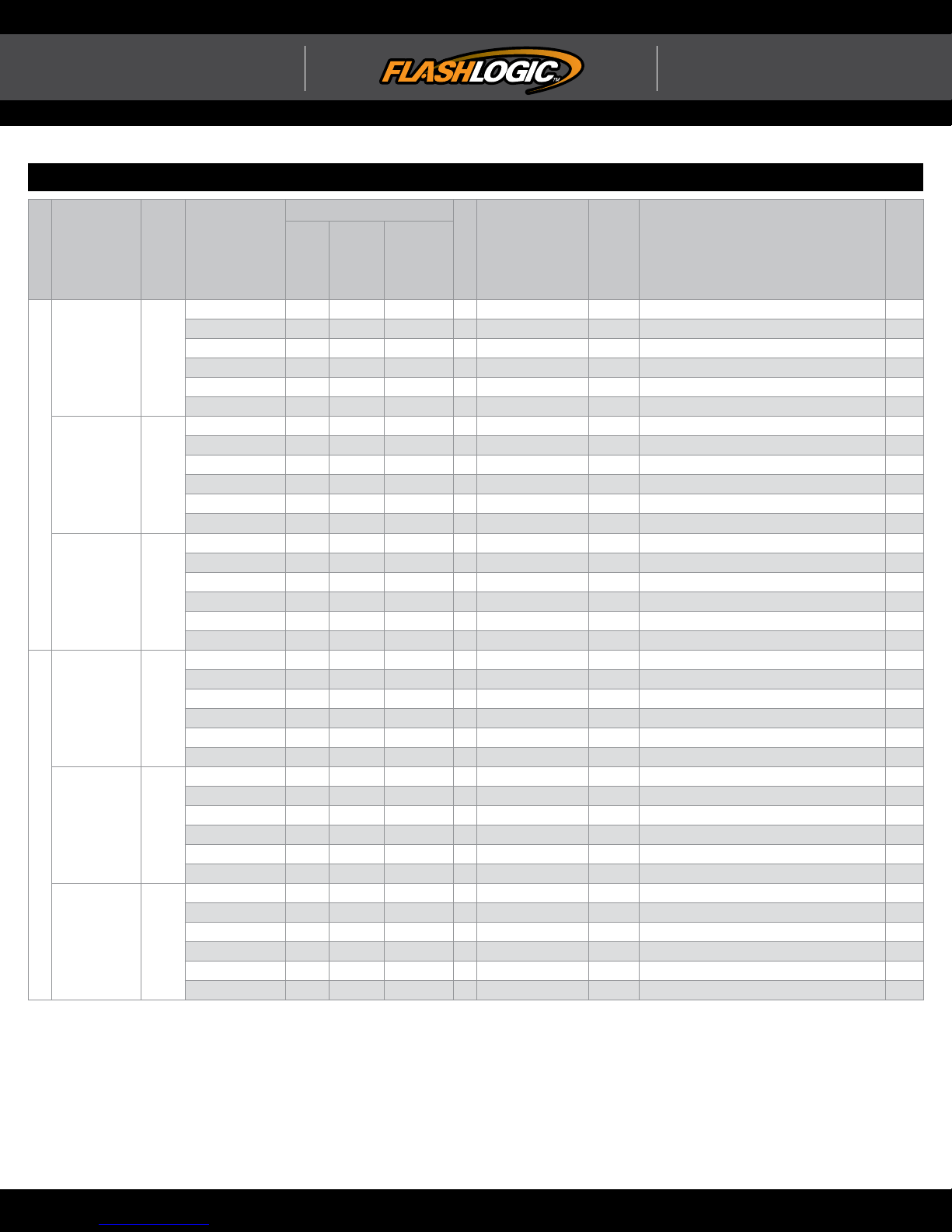
TYPE 2 - WIRE CROSS REFERENCE CHART
CONNECTOR
MAKE
MODEL
Cobalt 07-10
HHR 07-11
CHEVROLET
Malibu
Malibu Hybrid
Malibu MAXX
G6 07-09
Pursuit / G5 07-10
PONTIAC
Solstice 07-09
YEAR
WIRE
DESCRIPTION
Ignition ~ Green 6 pin 3 Pink or Yellow (+) Ignition switch A
Accessory ~ Green 6 pin 4 Brown (+) Ignition switch A
Passlock ~ Green 6 pin 5 White ~ Ignition switch A
12V ~ Green 6 pin 2 Red/White (+) Ignition switch A
Data (SWC) OBDII ~ 16 pin 1 Green (DATA) OBDII D
Security Light C2 White 72 pin 11 DkGreen (DATA) BCM B
Ignition ~ Green 6 pin 3 Pink or Yellow (+) Ignition switch A
Accessory ~ Green 6 pin 4 Brown (+) Ignition switch A
Passlock ~ Green 6 pin 5 White ~ Ignition switch A
12V ~ Green 6 pin 2 Red/White (+) Ignition switch A
Data (SWC) OBDII ~ 16 pin 1 Green (DATA) OBDII D
Security Light C2 White 72 pin 11 DkGreen (DATA) BCM B
Ignition ~ Green 6 pin 3 Pink or Yellow (+) Ignition switch A
Accessory ~ Green 6 pin 4 Brown (+) Ignition switch A
07-12
Passlock ~ Green 6 pin 5 White ~ Ignition switch A
08-12
12V ~ Green 6 pin 2 Red/White (+) Ignition switch A
07-09
Data (SWC) OBDII ~ 16 pin 1 Green (DATA) OBDII D
Security Light C2 White 72 pin 11 DkGreen (DATA) BCM B
Ignition ~ Green 6 pin 3 Pink or Yellow (+) Ignition switch A
Accessory ~ Green 6 pin 4 Brown (+) Ignition switch A
Passlock ~ Green 6 pin 5 White ~ Ignition switch A
12V ~ Green 6 pin 2 Red/White (+) Ignition switch A
Data (SWC) OBDII ~ 16 pin 1 Green (DATA) OBDII D
Security Light C2 White 72 pin 11 DkGreen (DATA) BCM B
Ignition ~ Green 6 pin 3 Pink or Yellow (+) Ignition switch A
Accessory ~ Green 6 pin 4 Brown (+) Ignition switch A
Passlock ~ Green 6 pin 5 White ~ Ignition switch A
12V ~ Green 6 pin 2 Red/White (+) Ignition switch A
Data (SWC) OBDII ~ 16 pin 1 Green (DATA) OBDII D
Security Light C2 White 72 pin 11 DkGreen (DATA) BCM B
Ignition ~ Green 6 pin 3 Pink or Yellow (+) Ignition switch A
Accessory ~ Green 6 pin 4 Brown (+) Ignition switch A
Passlock ~ Green 6 pin 5 White ~ Ignition switch A
12V ~ Green 6 pin 2 Red/White (+) Ignition switch A
Data (SWC) OBDII ~ 16 pin 1 Green (DATA) OBDII D
Security Light C2 White 72 pin 11 DkGreen (DATA) BCM C
NAME
COLOR
TYPE
POSITION
WIRE
COLOR
POLARITY
MODULE
LOCATION
COMPONENT
LOCATOR
WWW.FLASHLOGIC.COM Automotive Data Solutions Inc. © 2017
Page 8
ADS-AL(DL)-GM2 T2 2-2 PAGE X-X
INSTALL GUIDE
U.S. Patent No. 8,856,780
ALL IN ONE
General Motors
Page 8 of 11 FLC-AL(DL)-GM2-EN 20170531
Doc. No.: ##39835##
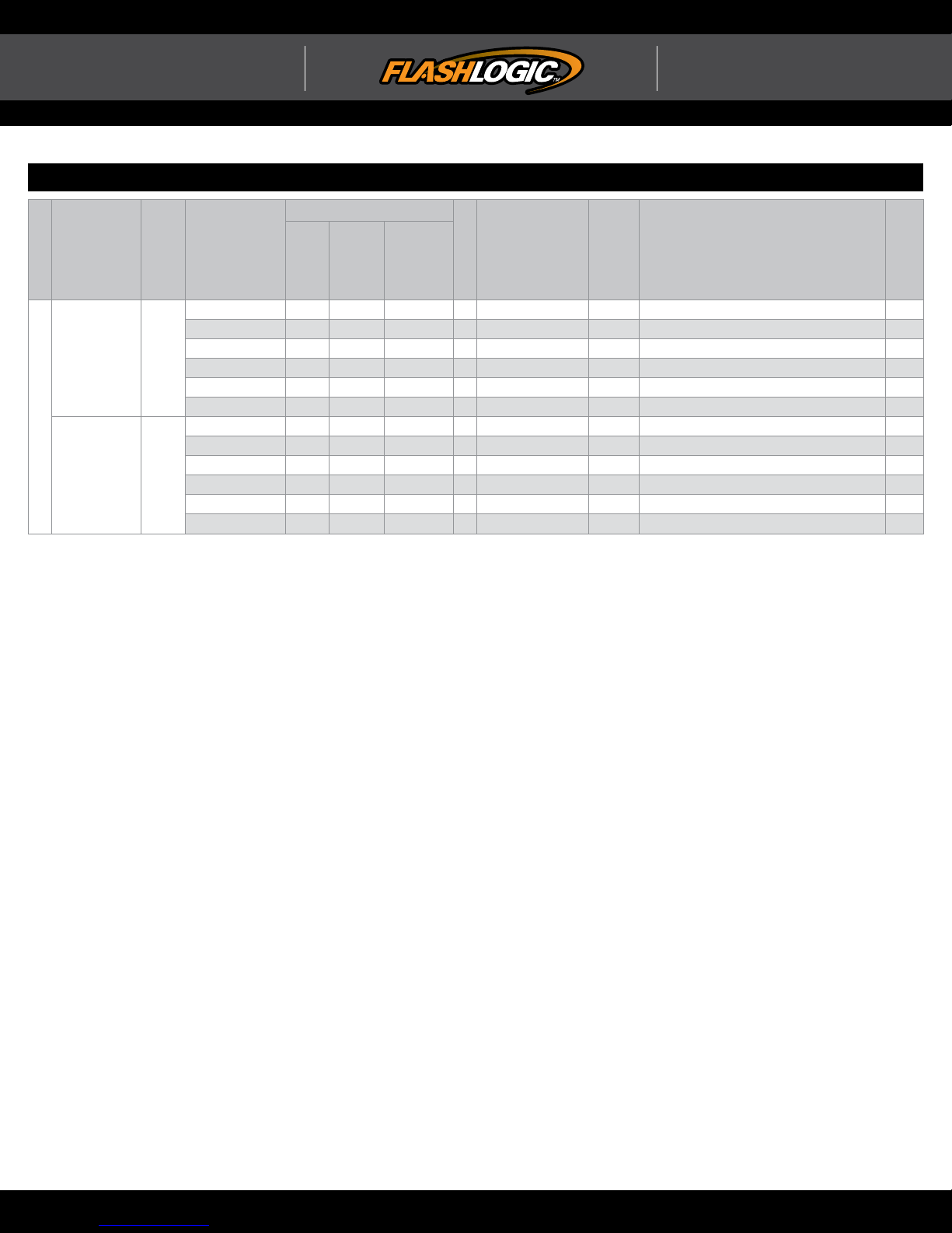
TYPE 2 - WIRE CROSS REFERENCE CHART
CONNECTOR
MAKE
MODEL
Aura / Hybrid 07-10
SATURN
Sky 07-09
YEAR
WIRE
DESCRIPTION
Ignition ~ Green 6 pin 3 Pink or Yellow (+) Ignition switch A
Accessory ~ Green 6 pin 4 Brown (+) Ignition switch A
Passlock ~ Green 6 pin 5 White ~ Ignition switch A
12V ~ Green 6 pin 2 Red/White (+) Ignition switch A
Data (SWC) OBDII ~ 16 pin 1 Green (DATA) OBDII D
Security Light C2 White 72 pin 11 DkGreen (DATA) BCM B
Ignition ~ Green 6 pin 3 Pink or Yellow (+) Ignition switch A
Accessory ~ Green 6 pin 4 Brown (+) Ignition switch A
Passlock ~ Green 6 pin 5 White ~ Ignition switch A
12V ~ Green 6 pin 2 Red/White (+) Ignition switch A
Data (SWC) OBDII ~ 16 pin 1 Green (DATA) OBDII D
Security Light C2 White 72 pin 11 DkGreen (DATA) BCM C
NAME
COLOR
TYPE
POSITION
WIRE
COLOR
POLARITY
MODULE
LOCATION
COMPONENT
LOCATOR
WWW.FLASHLOGIC.COM Automotive Data Solutions Inc. © 2017
Page 9
INSTALL GUIDE
ALL IN ONE
General Motors
U.S. Patent No. 8,856,780
Page 9 of 11 FLC-AL(DL)-GM2-EN 20170531
Doc. No.: ##39835##
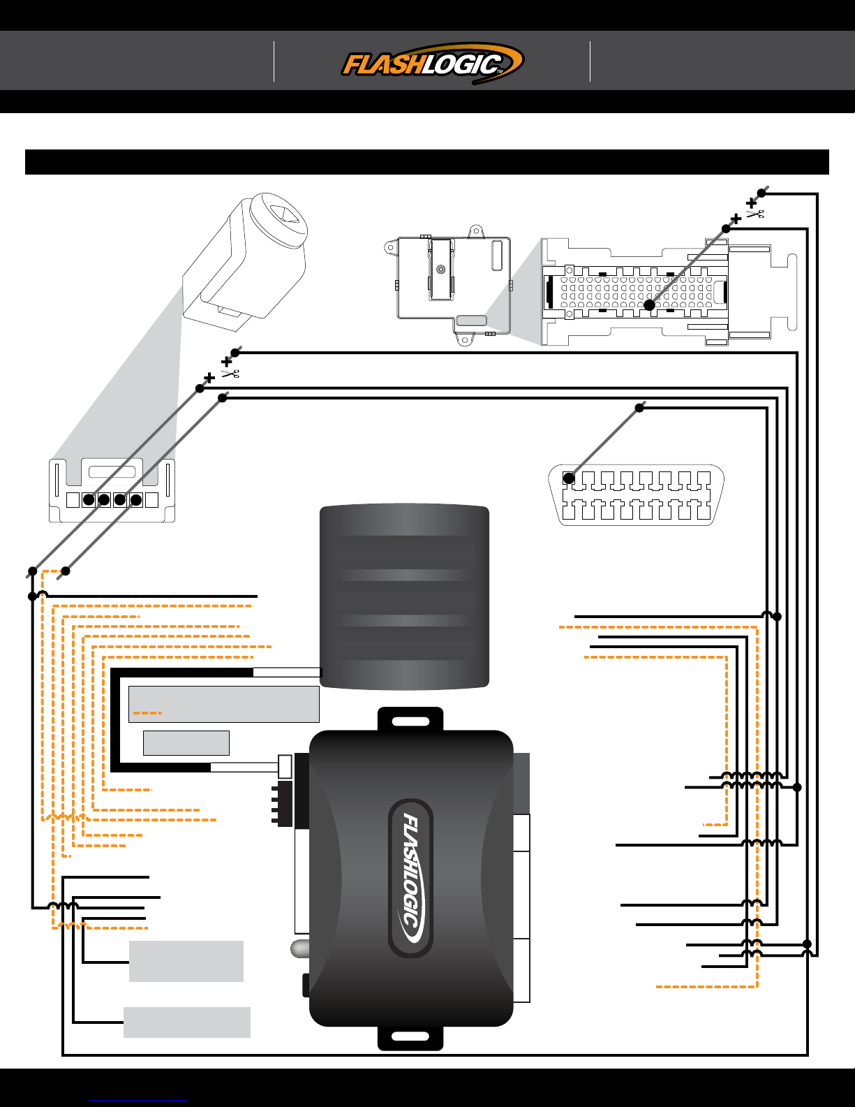
TYPE 2 - WIRING DIAGRAM
SECURITY LIGHT
72
18
87654321
161514131211109
ACC (+)
5
12V (+)
4
IGNITION SWITCH
PASSLOCK
IGN (+)
3
123456
2
IGNITION SWITCH
CONNECTOR - WHITE
BCM
REMOTE STARTER
C2 - WHITE
55
1
DATA (SWC)
1
OBDII CONNECTOR LOCATED
UNDER DRIVER SIDE DASH
11
ACCESSORY (+)
ACCESSORY (+)
TACH (AC) INPUT
TRUNK/TAILGATE WINDOW RELEASE OUTPUTTRUNK/TAILGATE WINDOW RELEASE OUTPUT
LEGEND
N/A
NOT REQUIRED IN DATA MODE (1-WAY)
NOT REQUIRED IN DATA MODE (2-WAY)
USE DATA MODE
OR HARDWIRE MODE
GWR (-) INPUT - BLUE/WHITE
GWR (-) INPUT - BLUE/WHITE
GROUND - BLACK
GROUND - BLACK
LOCK/ARM (-) INPUT - GREEN/BLACK
LOCK/ARM (-) INPUT - GREEN/BLACK
UNLOCK/DISARM (-) INPUT - BLUE/BLACK
TRUNK/TAILGATE WINDOW REL. (-) INPUT - RED/WHITETRUNK/TAILGATE WINDOW REL. (-) INPUT - RED/WHITE
UNLOCK/DISARM (-) INPUT - BLUE/BLACK
SECURITY LIGHT - PURPLE/YELLOW
SECURITY LIGHT - PURPLE/YELLOW
AUTO-RELOCK (+) INPUT - WHITE
AUTO-RELOCK (+) INPUT - WHITE
ACCESSORY (+) INPUT - BLACK/WHITEACCESSORY (+) INPUT - BLACK/WHITE
RAP SHUTDOWN (-) OUTPUT -
TACH (AC) OUTPUT - PURPLE/WHITE
TACH (AC) OUTPUT - PURPLE/WHITE
CONNECT TO DRIVER DOOR
SWITCH TO TURN OFF RADIO
AT THE END OF THE
REMOTE START SEQUENCE
CONNECT TO CONSTANT 12V (+)
TO ENABLE AUTOMATIC RELOCK
AFTER START
(NC) PURPLE/BLACK
(NC) PURPLE/BLACK
TACH (AC) INPUT
UNLOCK (-) OUTPUT
UNLOCK (-) OUTPUT
LOCK (-) OUTPUT
LOCK (-) OUTPUT
GWR (-) OUTPUT
GWR (-) OUTPUT
DATA MODE
(NC) WHITE
(NC) WHITE
12V (+) - RED
12V (+) - RED
(NC) BROWN
(NC) BROWN
GROUND (-)
GROUND (-)
DATA MODE
GREENRAP SHUTDOWN (-) OUTPUT - GREEN
<- REQUIRED
<- REQUIRED
<- REQUIRED
<- REQUIRED
<- REQUIRED
<- REQUIRED
<- REQUIRED
REQUIRED ->
REQUIRED ->
REQUIRED ->
OPTIONAL ->
OPTIONAL ->
IGNITION (+) OUTPUT
IGNITION (+) OUTPUT
BRAKE (+) INPUT
BRAKE (+) INPUT
E-BRAKE STATUS (-) INPUT
E-BRAKE STATUS (-) INPUT
TRUNK STATUS (-) INPUT
TRUNK STATUS (-) INPUT
DOOR STATUS (-) INPUT
DOOR STATUS (-) INPUT
WHITE/BLACK - PASSLOCK CONNECTOR SIDE
WHITE/BLACK - PASSLOCK CONNECTOR SIDE
WHITE/RED - PASSLOCK VEHICLE SIDE
WHITE/RED - PASSLOCK VEHICLE SIDE
WHITE (NC)
WHITE (NC)
YELLOW/BLACK - DOOR STATUS (-) OUTPUT
YELLOW/BLACK - DOOR STATUS (-) OUTPUT
YELLOW/RED - TRUNK STATUS (-) OUTPUT
YELLOW/RED - TRUNK STATUS (-) OUTPUT
YELLOW - PASSLOCK
YELLOW - PASSLOCK
BROWN/RED (NC)
BROWN/RED (NC)
BROWN/YELLOW (NC)
BROWN/YELLOW (NC)
ORANGE/BLACK (NC)
ORANGE/BLACK (NC)
ORANGE/WHITE (NC)
ORANGE/WHITE (NC)
ORANGE - DATA (SWC)
ORANGE - DATA (SWC)
PINK/BLACK (NC)
PINK/BLACK (NC)
PINK - IGNITION (+) INPUT
PINK - IGNITION (+) INPUT
BLUE/RED - SECURITY LIGHT BCM SIDE
BLUE/RED - SECURITY LIGHT BCM SIDE
BLUE/YELLOW - SECURITY LIGHT VEHICLE SIDE
BLUE/YELLOW - SECURITY LIGHT VEHICLE SIDE
GREEN/RED - E-BRAKE STATUS (-) OUTPUT
GREEN/RED - E-BRAKE STATUS (-) OUTPUT
GREEN/YELLOW (NC)
GREEN/YELLOW (NC)
GRAY/RED - BRAKE (+) OUTPUT
GRAY/RED - BRAKE (+) OUTPUT
GRAY/YELLOW (NC)
GRAY/YELLOW (NC)
WWW.FLASHLOGIC.COM Automotive Data Solutions Inc. © 2017
Page 10
XX-XX PAGE X-XADS-AL(DL)-GM2 PAGE X-X
ADS-AL(DL)-GM2 73
ADS-DL-GM2 73
INSTALL GUIDE
U.S. Patent No. 8,856,780
ALL IN ONE
General Motors
Page 10 of 11 FLC-AL(DL)-GM2-EN 20170531
Doc. No.: ##39835##
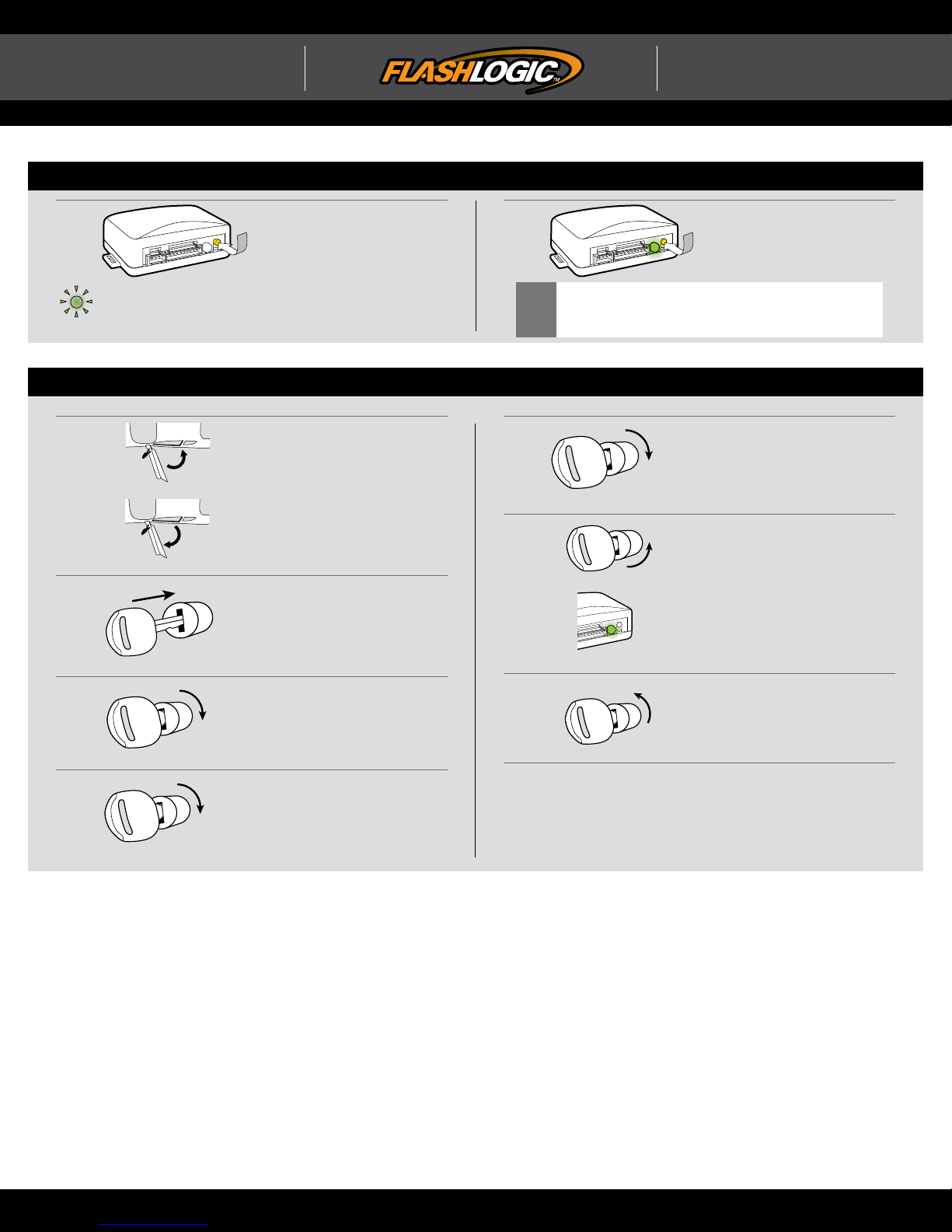
INSTALLATION MODE SELECTION
Press and release
1
LED fl ashes (1X) once = DATA MODE
LED fl ashes (2X) twice = STANDARD HARDWIRE MODE
programming button
to select installation mode.
2
After registration, follow Factory Reset Procedure to
change installation mode and restart this procedure.
!
Press and hold
programming button
until LED turns solid GREEN
to register selection.
MODULE PROGRAMMING PROCEDURE
1
Close driver door.
Re-open driver door to wake up
data bus.
Insert key into ignition.
5
6
START
ON
Turn key to Start position and
Hold for 3 seconds.
Release key from Start position
and return to ON position.
2
3
4
ACC
ON
Wait 3 seconds.
Turn key to Accessory position.
Wait 3 seconds.
Turn key to ON position.
Wait 3 seconds.
7
8
OFF
Wait, LED will turn solid GREEN
for 2 seconds.
Turn key to OFF position.
Module Programming
Procedure completed.
WWW.FLASHLOGIC.COM Automotive Data Solutions Inc. © 2017
Page 11
XX-XX PAGE X-XCLASSIC PAGE 1-1
XX-XX PAGE X-X
NOTICE
PATENT PAGE X-X
INSTALL GUIDE
U.S. Patent No. 8,856,780
ALL IN ONE
General Motors
Page 11 of 11 FLC-AL(DL)-GM2-EN 20170531
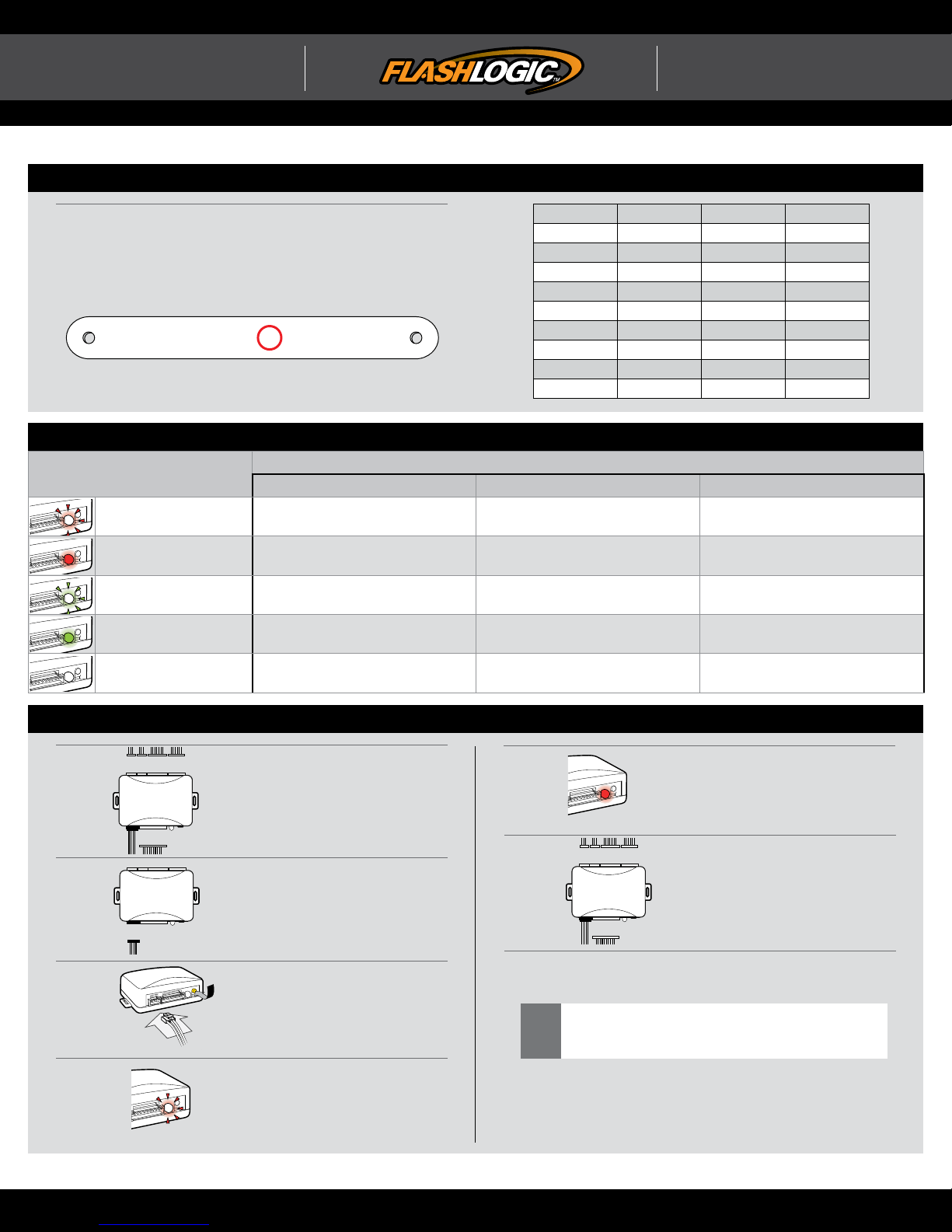
IDENTIFY VEHICLE YEAR
1 Locate the Vehicle Identifi cation Number (VIN), identify the 10th
character then match it to its corresponding year.
Æ
4 Y 1 N53 A 5 T A L 8 D 5 R 0 X
Æ
A
1980
B
1981
C
1982
D
1983
E
1984
F
1985
G
1986
H
1987
J
1988
K
1989
L
M
N
P
R
S
T
V
W
X
Doc. No.: ##39835##
1990
1991
1992
1993
1994
1995
1996
1997
1998
1999
Y
1
2
3
4
5
6
7
8
9
2000
2001
2002
2003
2004
2005
2006
2007
2008
2009
A
2010
B
2011
C
2012
D
2013
E
2014
F
2015
G
2016
H
2017
J
2018
K
2019
MODULE DIAGNOSTICS
LED STATUS
Flashing RED
Solid RED Waiting for more vehicle information Incorrectly programmed
Flashing GREEN
DURING PROGRAMMING DURING REMOTE START WITH IGNITION OFF
Missing/wrong information from
fi rmware or vehicle
Additional steps required to complete
programming
Incorrectly programmed Incorrectly programmed or connected
Correctly programmed and
operational
DIAGNOSTICS
Not programmed waiting for more
vehicle information
False ground when running status
from remote starter
Solid GREEN then OFF Correctly programmed Reset in progress Reset in progress
OFF No activity or already programmed
Invalid ground when running status
from remote starter
At rest and ready for a remote start
sequence
FACTORY RESET PROCEDURE
1
2
3
4
DISCONNECT all connectors
from module EXCEPT the black
4-PIN standard or optional data
connector.
DISCONNECT black 4-PIN
standard or optional data
connector.
PRESS AND HOLD programming
button while connecting either
4-PIN standard or optional data
connector.
When LED fl ashes red,
RELEASE programming button.
5
6
7
Failure to follow procedure may result with a DTC or a
CHECK ENGINE error message.
!
LED will turn solid red for 2
seconds.
RESET COMPLETED.
RECONNECT all connectors.
Repeat programming procedure.
This product is protected by one or more of the following patents: U.S. LETTERS PATENT NO. 5,719,551; 6,011,460; 6,243,004; 6,249,216; 6,275,147; 6,297,731; 6,346,876; 6,392,534; 6,529,124; 6,696,927; 6,756,885; 6,756,886; 6,771,167; 6,812,829; 6,924,750;
7,010,402; 7,031,826; 7,046,126; 7,061,137; 7,068,153; 7,015,830; 7,205,679; 7,224,083; 7,369,936; 7,378,945; 7,489,233; 7,501,937; CANADIAN PATENT NO. 2,320,248; 2,415,023; 2,426,670; 2,414,991; 2,415,011; 2,415,027; 2,415,038; 2,415,041; 2,502,893; 2,451,490;
2,452,296; 2,451,487; EUROPEAN PATENT NO. 1,053,128; DE 69807-941T2; U.S. 20020145535; 20060129282; 20060129284; 20040017284; 20080030316; 20090079552; EP1500565; 1538038; 1538037;
WWW.FLASHLOGIC.COM Automotive Data Solutions Inc. © 2017
 Loading...