

Flashforge USA Creator Startup Manual
Creator
Quick Start Guide
Version 2.0 (January 2014)

4
Section 1: What’s Included in the Box?
5
Section 2: Unboxing
8
Section 3: Initial Hardware Installation
11
Section 4: Software Installation
17
Section 5: USB Connection & Temperature Setting
22
Section 6: Filament
22
Installing the Filament
23
Feeding the Filament Using LCM Screen
24
Withdrawing the Filament Using LCM Screen
25
Setting the Parameter
26
Initial Print
28
Dual Extruder Print
Contents
2
WARNING:
Prior to powering on the Creator, make sure the power supply switch is set
to 115v if you are located in the United States. For other countries, please
refer to your country standards. Failure to do so will damage the
motherboard. For instructions on how to do this, please refer to page 8.
Precautions:
Please make sure to read this page carefully prior to setting up and operating the Creator.
The Creator is very sensitive to static electricity, so please make sure you contact a grounded
object before operating the machine.
- Before repairing or making any alterations to the Creator, it is essential that the machine is
turned off, and the power cord is unplugged.
- The Creator operates at a very high temperature; allow the nozzle, extruded plastic and heating
plate to cool before touching.
- Some plastic filaments may give off a slight odor when heated. Because of this, the machine
should always operate in a well-ventilated area.
- Do not wear gloves when operating or repairing, as entanglement may occur and cause injury.
- Do not leave the machine unattended when in operation.
3

1 What’s Included in the Box?
Along with your Creator 3D printer, the box also contains the following.
An accessory box on top of the Creator:
Single or dual extruder heads,
1 or 2 filament holders,
SD Card,
Bolt tool plate, hex wrench toolbox.
Under the Creator’s build platform, there are 2 filaments:
2.2 pounds (1 kg) ABS filament,
2.2 pounds (1 kg) PLA filament.
Under the Creator unit, you’ll find:
Power supply,
USB A to B cable,
2 filament guide tubes
4
CAUTION
Handle the package and its contents with extra care; do not use any unnecessary force.
Do not remove the thin yellow film from the heating plate. It is heat resistant tape that
improves the adhesion of the extruded plastic to the plate.
Do not remove the wrapping around the nozzle. It consists of a ceramic fiber fabric and heat
resistant tape that helps to keep the nozzle at a constant temperature.
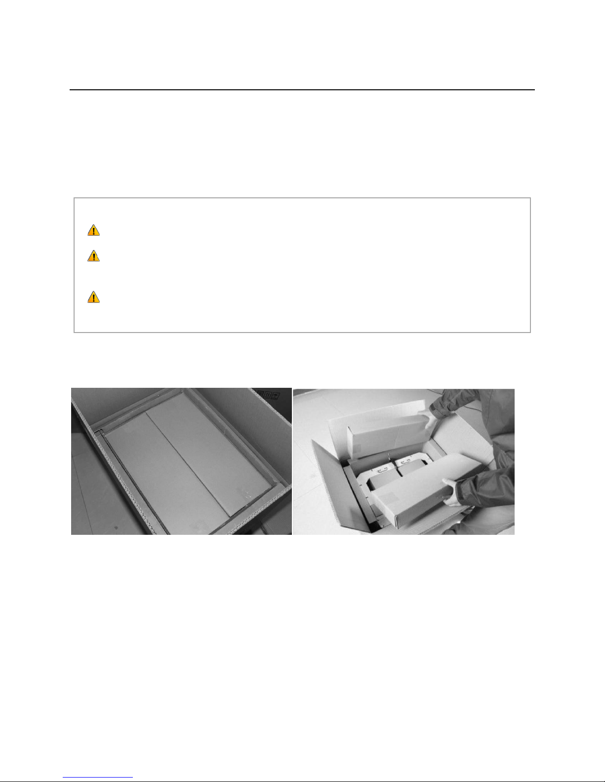
2 Unboxing
The Creator is carefully packaged at the FlashForge manufacturing facility. Please follow the unboxing
steps laid out below.
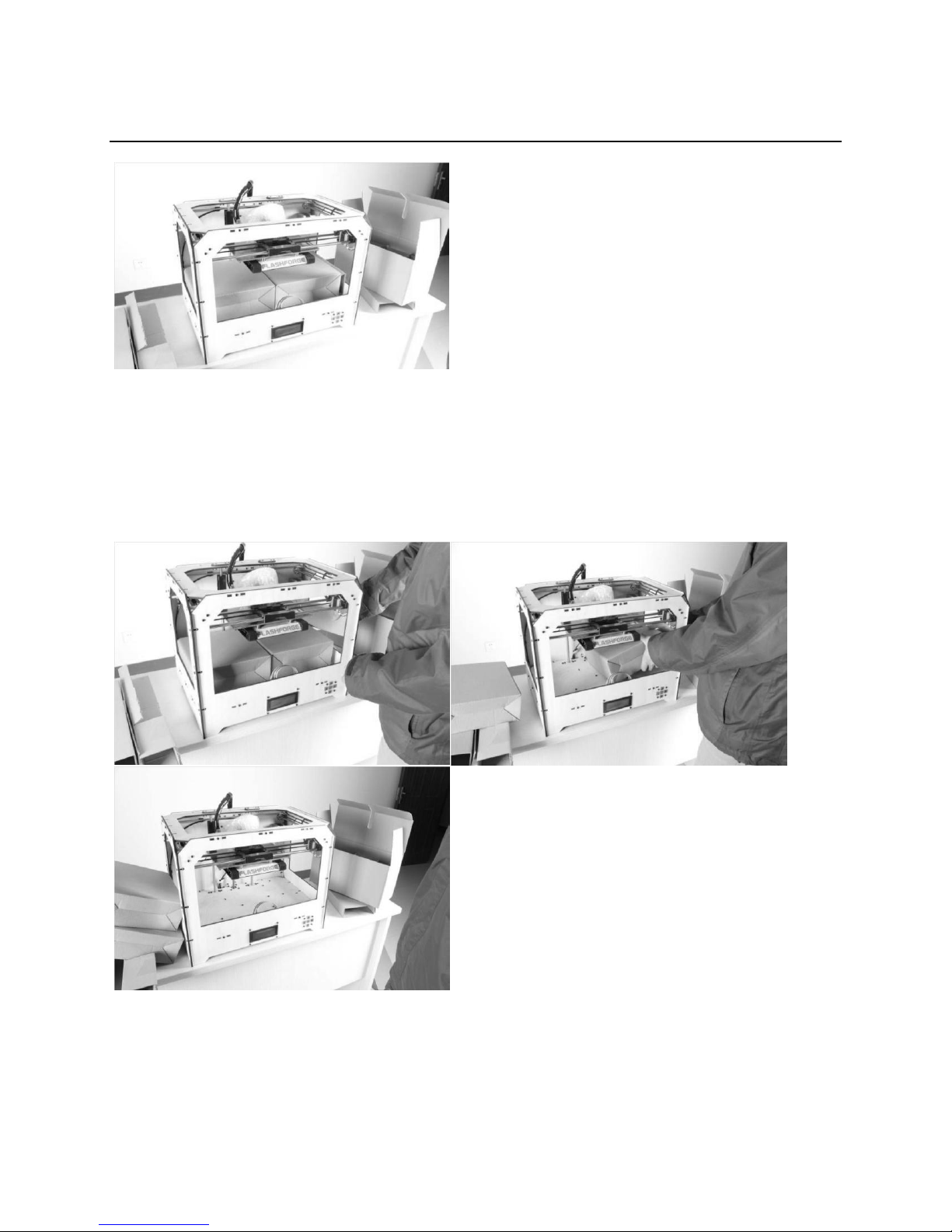
First, place the box on the floor in a clean and flat surface. Remove the top carton and pull out the
cardboard packing that encloses the Creator.
You can see the top of the printer along with more boxes inside. The large box with the black wire is the
accessory box. This contains the extruder(s), SD card, and other important components. Do not
remove the accessory box and its contents yet. Note: Do not lift the box by the black cable. Doing so
could cause damage.
Next, take the Creator out of the box by grasping the outer frame. Be sure to grasp only the frame.
Gently lift and transfer the printer to your work surface, as shown on the next page.
5
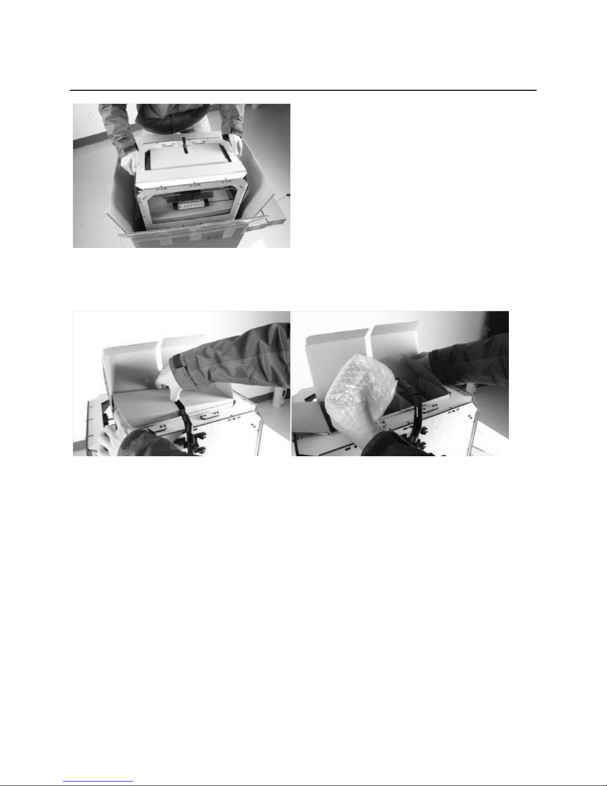
With the Creator removed, you will find the power supply and cable, USB A to B cable, and a filament
guide tube. Remove them from the box and set them aside. Now, open the accessory box and remove
the accessory sleeve.
You will find the extruder in the protective packaging along the black cable. Carefully remove it and
place it on your work surface. Remove the cardboard packing material and take the accessory box from
the printer; set it aside for later.
The build platform should now be visible. It is an aluminum plate covered in a thin polyamide film. This
is the surface that your objects will be printed on. Note: Remember not to remove this film.
The next step is to raise the build platform. There are two ways to do this:
1. Turn the screw that is behind the rotating platform.
2. Grasp the printing platform with one hand on each side, raising it slowly and keeping it level.
Stop once the platform is just shy of the bronze nozzle.
6
Next, you should be able to see underneath the build platform. Here, you'll find the filament (either one
or two rolls depending on whether your Creator has single or dual extruders). It’s easiest to remove the
filament by setting aside the remaining packaging material.
To do this, remove the long box in the front, then the small box on the right, and finally the two wire
trays. You have now finished unboxing! The next task is to setup the hardware.
7
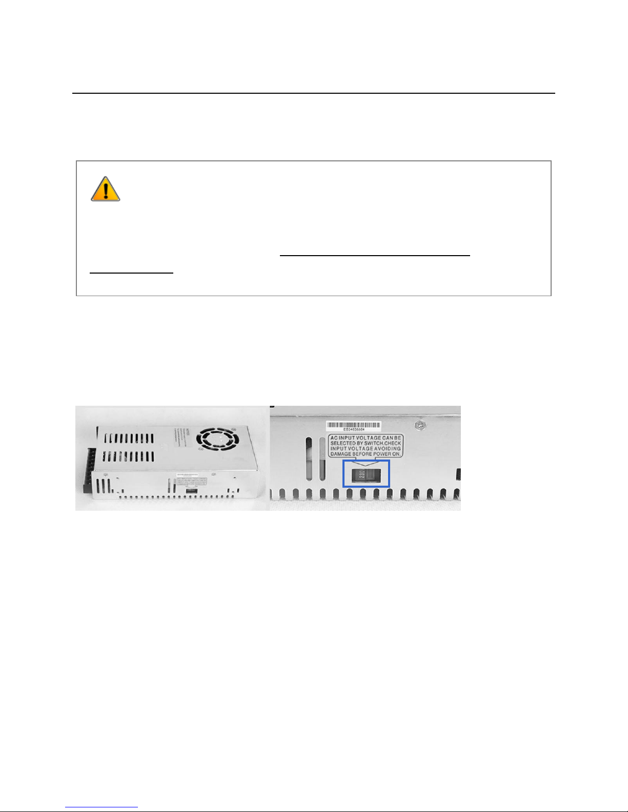
WARNING:
Prior to powering on the Creator, make sure the power supply switch is set
to 115v if you are located in the United States. For other countries, please
refer to your country standards. Failure to do so will damage the
motherboard.
3 Initial Hardware Installation
Prior to installation, please make sure that the red power supply switch at the bottom of the Creator is
set to 115V (for United States).
To do this, begin by carefully placing the Creator on one of its sides so that the bottom is exposed. You
will see the Creator’s power supply. Using a flathead screwdriver, switch the red power supply switch so
that it displays 115V, as shown below. Now you are ready to install the extruder.
You'll need two silver screws from the bolt tool plate found in the accessory box and the appropriate
hex wrench.
First, lower the build platform using one of the methods described in the previous section. Holding the
extruder by both sides, take it out of the accessory sleeve and position it on the extruder seat with the
fan facing forward. Align the screw holes and fasten with the shortest silver screws.
8
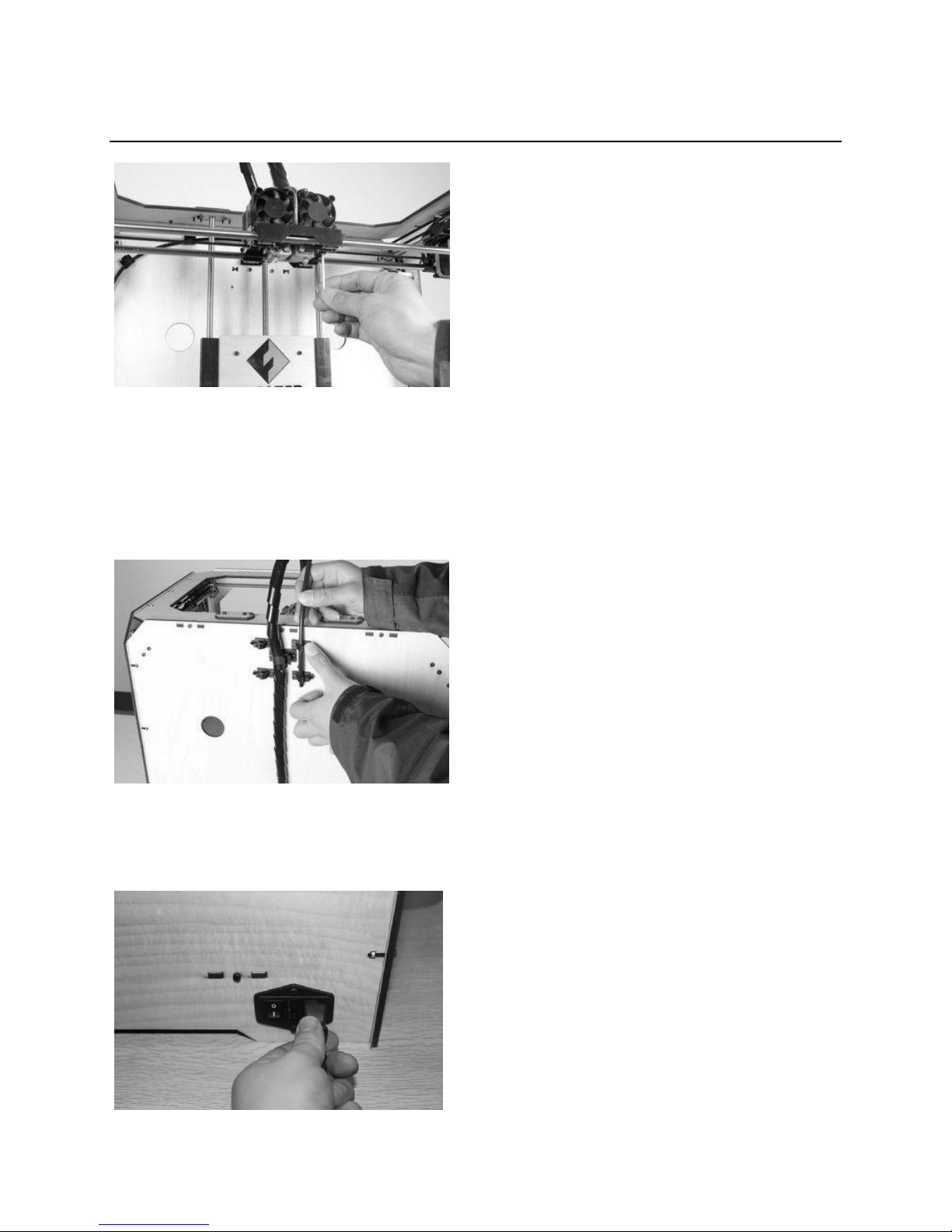
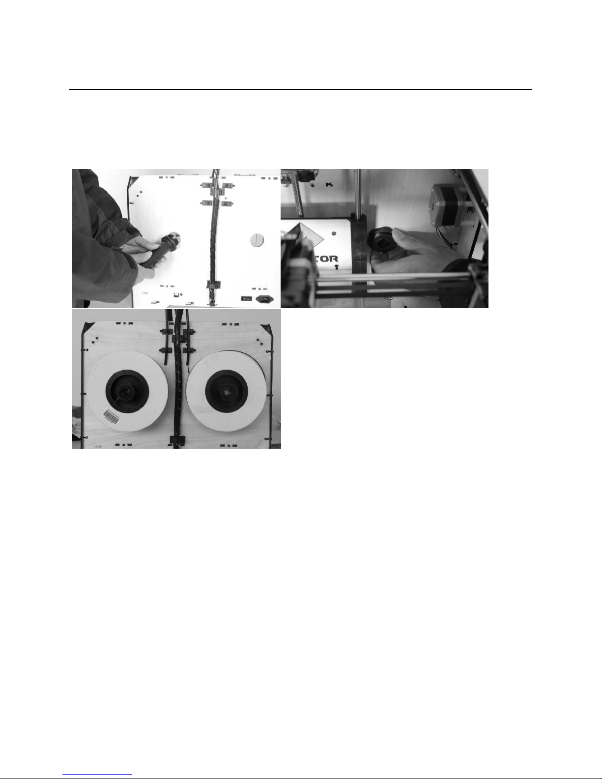
Next is the installation of the filament bracket. If you have two brackets, install one on each side; If you
only have one, install it on the right hand side (when viewing the creator from the front).
The installation of the filament bracket is very simple – just insert it into the circular opening and tighten
the nut behind. Then, install the filament guide tube to the empty spot on the extruder. Place one end
of the guide tube into the hole.
The hardware installation is almost complete.
Next, with the power switch in the 'OFF' position, confirm that the power cord is plugged into the power
outlet next to the power switch.
9
Now plug the USB A to B cable into the USB B-type port, do not plug the other end in yet.
Finally, take the filament out of the box, install it onto the bracket and screw in the nut. Do not over
tighten.
Congratulations! You have completed the initial hardware installation! If you're ready to start printing,
proceed to the next step: Software Installation.
10
 Loading...