

Page 1
This guide is only applicable to FLASHFORGE Inventor 3D printer
The User Guide is in the SD card.
USERGUIDE
2. Hot! Avoid touching the heating nozzle in operation.
3. Moving parts in printer may cause injury. Do not wear gloves
or other sources of entanglement in operation.
WARNING
1. Do not remove the wrapping around the nozzle.
INVENTOR
Quick Start Guide
SZ14-EN-A02
Page 2
01
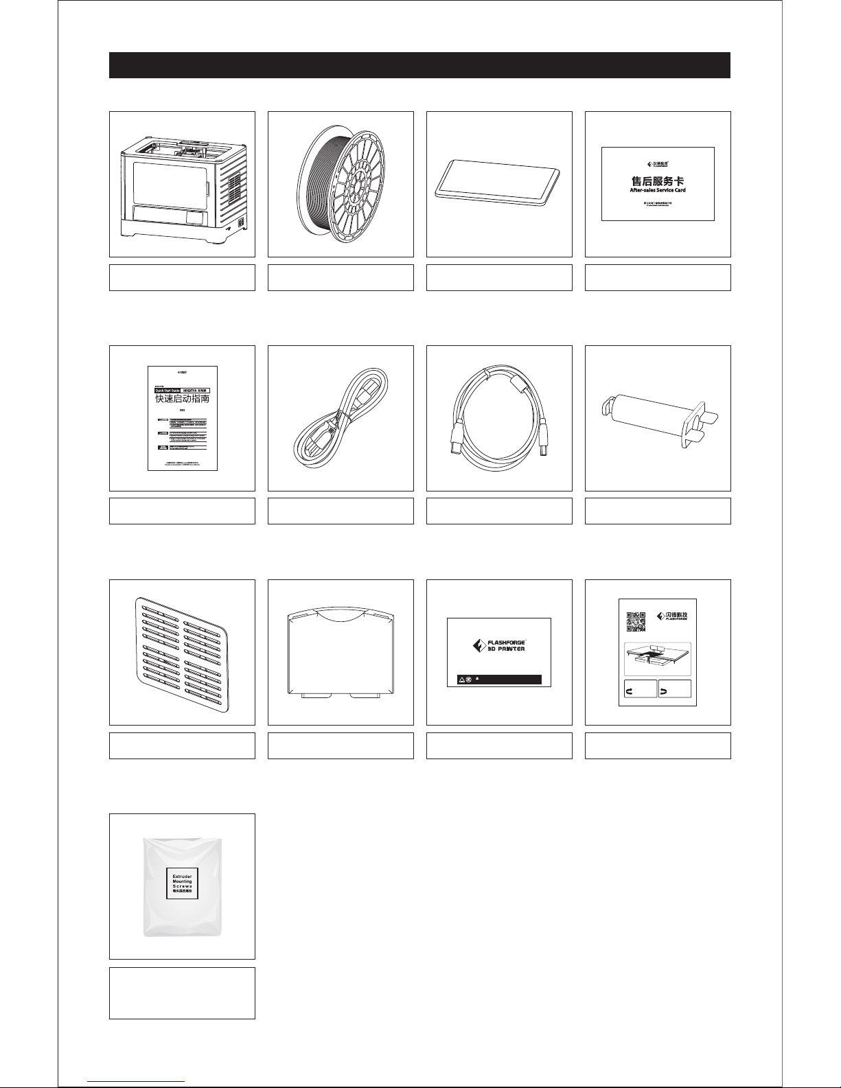
Kit Contents
3D Printer
Filament Spool x 2
Lid
After-sales Service Card
Power Cable USB Cable
Quick Start Guide
Build Tape x 2
Leveling Card
Extruder’s
Accessory Kit
Do Not Touch
请勿触摸
CAUTION
注意
1.Extruder hot during operation.
使用过程中喷头会发热。
2.Heating plate hot during operation.Allow surface to cool before servicing.
使用过程中加热平台会发热,待平台表面冷却后再操作。
顺时针旋转螺母
升高打印平台。
即减少平台与喷嘴之 间
的距离。
逆时针旋转螺母
降低打印平台。
即增加平台与喷嘴之 间
的距离。
调整平台支架下方 的螺母,直 至纸片在喷 嘴与平台间 的
运动感受到轻微的 阻力。
打印平台调 节专用
扫描二维码,观 看调平指导视 频!
Spool holder x 2
Side Panel x 2 Tool Box
Tool Box Contents:
SD Card / Tweezer / Graver / Scraper / Screw Box* / Wrench / Grease
Allen Wrench / Phillips Screwdriver / Wrench / Unclogging Pin Tool
Extruder’s Accessory Kit Contents:
M3 x 8 Bolt x 2 / M3 x 6 Bolt / Turbofan Baffle
*Screw Box Contents: PTFE tube, Screws, Leveling Knob
Page 3
Getting to Know Your Inventor
02
22
18 19 20 21
1
3
4
5
6
7
9
10
17
8
2
11
12
13
14
15
23
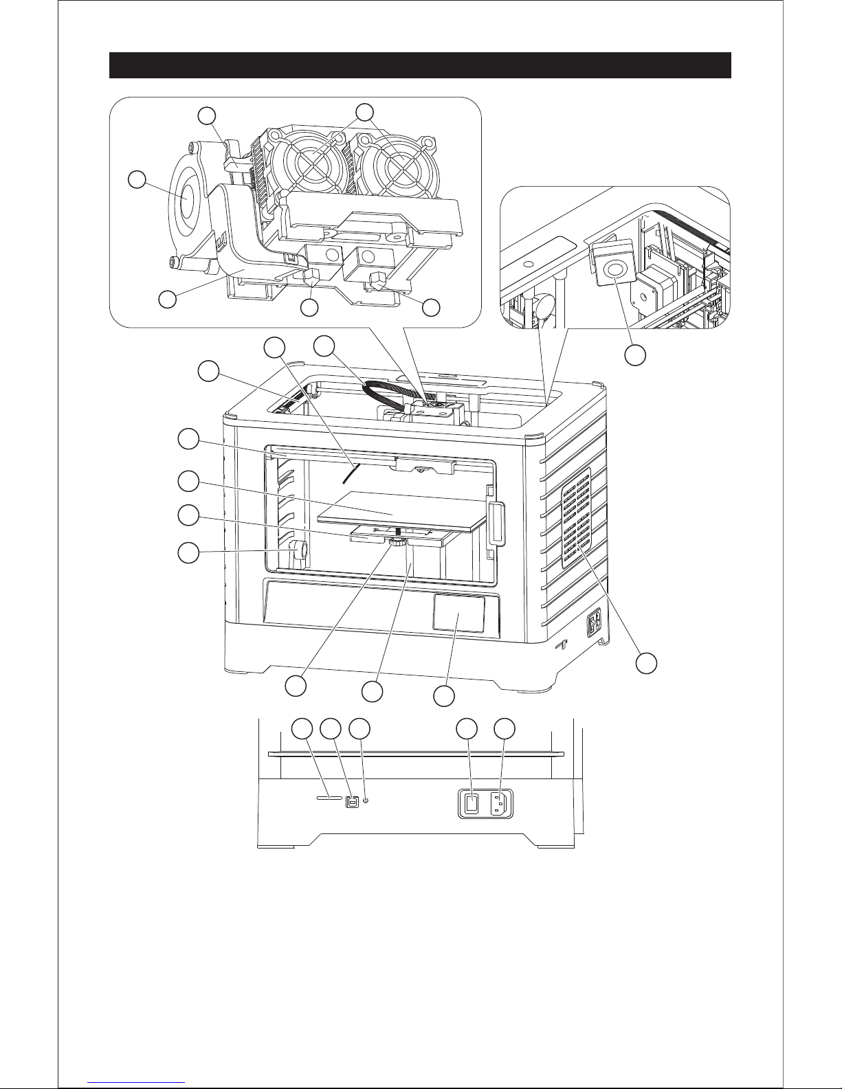
Extruder
Camera
1.Extruder Cable Bunch 2.Filament Guide Tube 3.Y-Axis Guide Rod 4.X-Axis Guide Rod
5.Build Plate 6.Build Platform
7.Bracket
8.LevelingKnob
9.Z-Axis Guide Rod
10.Touch Screen
11.Cooling Fan 12.Spring Presser
13.Turbofan 14.Turbofan Baffle
15.Left Nozzle
18.SD Card Input
19.USB Input
20.Reset Button
22.Power Input 23.Camera
17.Side Panel
16
21.Power Switch
16.Right Nozzle
Page 4
Unpacking
03
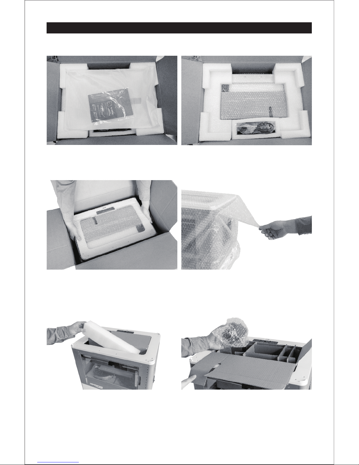
1.Open box and remove bag containing the lid,
Quick start guide, After-sales service card,
levelling card, and two build taps.
2.Take the power cable and two foam sheets
out from the top.
3.Firmly grasp the two sides handles of Inventor.
Lift it out from the carton and place it on a
stable surface. Then you will see the Toolbox
and USB cable in the shipping box.
4.Remove the packing bag.(Tip:Save your
packaging for future transportation and
storage.)
5.Take foam out of the Inventor.
6.Open the box inside the printer. It should
contain: dual extruder, two side panels,
and extruder's accessory kit. Remove dual
extruder and place it on a clean surface.
Note: the extruder cable is short; please do
not leave the extruder hanging by the cable.
Page 5
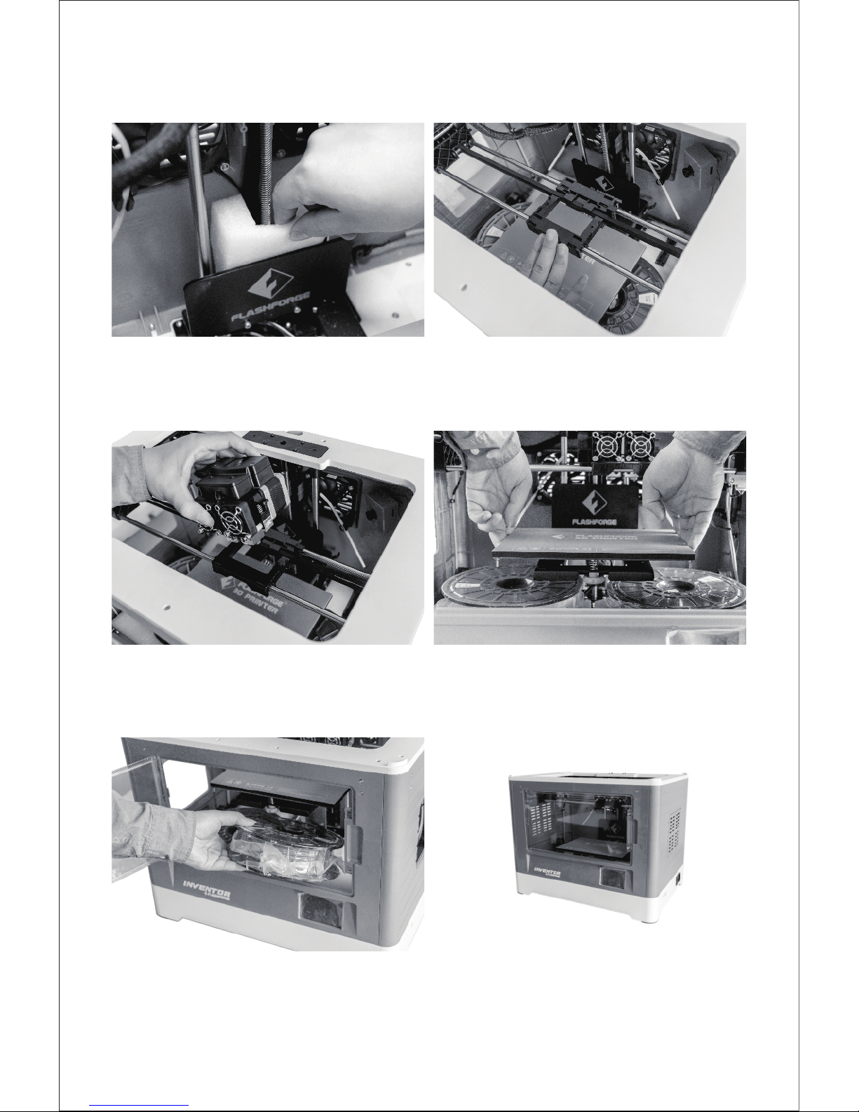
04
8.Remove the bubble wrap from extruder and
slide the x-axis rod to the middle of the printer.
10.Elevate the build plate to its limit.
Notes: Do not let build plate touch extruder.
11.Remove both filament rolls and foam pieces
from printer. Note: Take both spool holders
out of the foam.
9.Place the dual extruder on the extruder seat
as show.
7.Remove the foam from the back of the logo
board.
12.Lower the build plate fully. Congratulations!
You've unpacked your printer.
(Tip: Save packaging for future transportation
and storage)
Page 6
05
Hardware Assembly
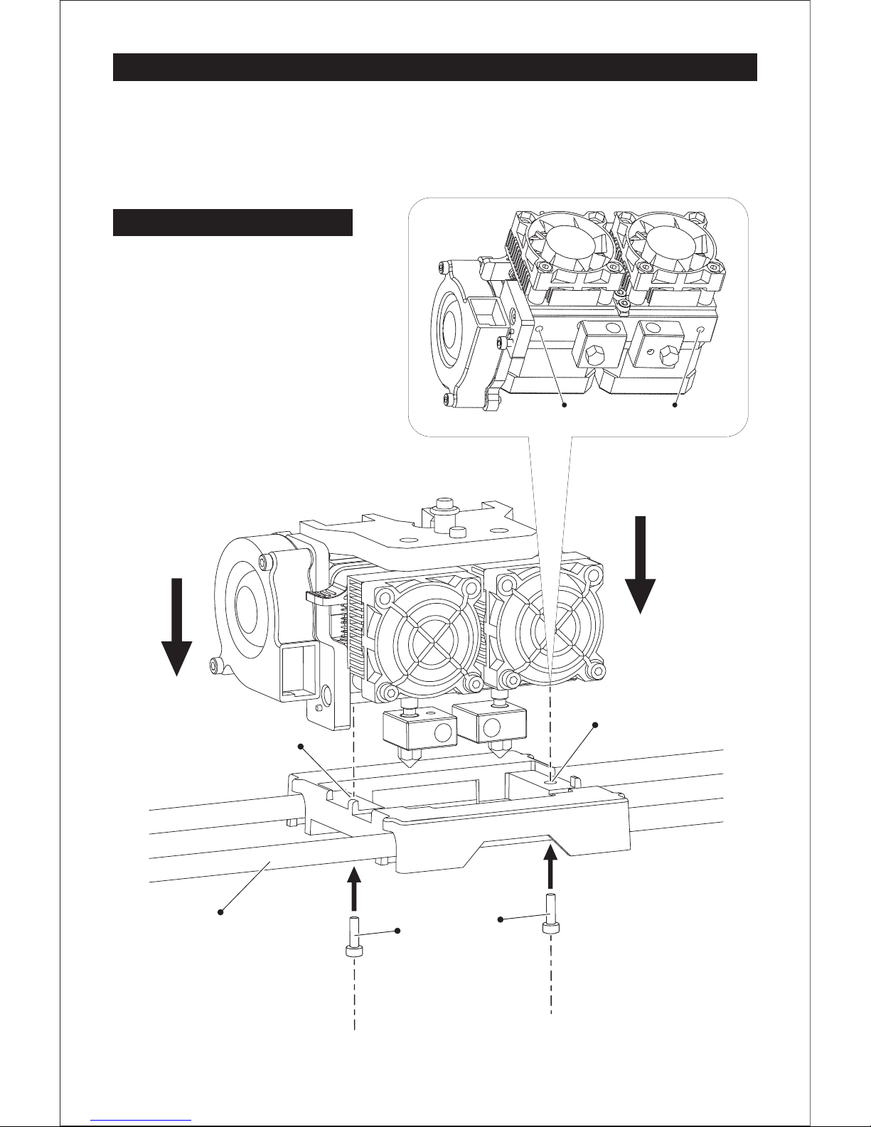
Extruder Assembly
1. Place the dual extruder on the extruder
seat.
2. Take the M2.5 Allen Wrench from the tool
bag and two M3 x 8 bolts(longer ones)
from the extruder’s accessory kit.
3. Adjust the extruder location to align the
bolt holes.
4. Secure the extruder onto the extruder
seat by screwing the M3 x 8 bolts in.
Bolt Hole Bolt Hole
M3 x 8 bolts
X-Axis Guide Rod
Bolt Hole
Bolt Hole
Page 7
06
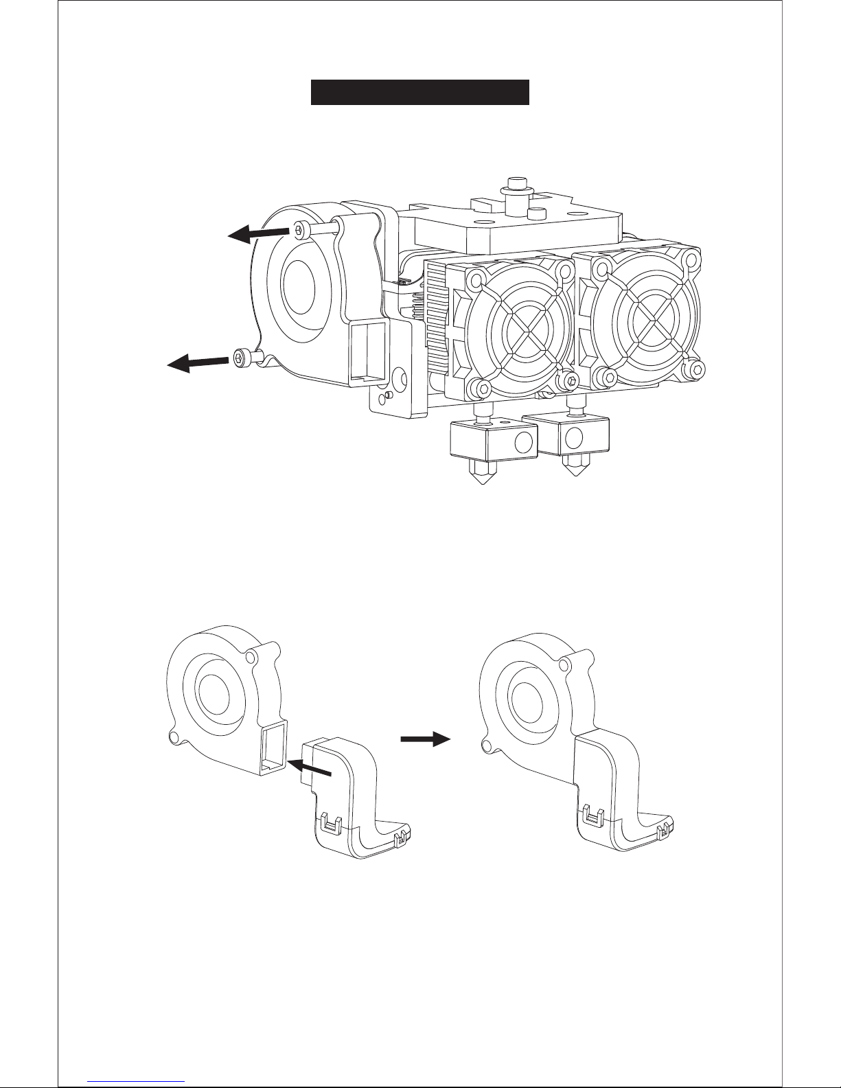
Turbofan Baffle Assembly
1. Use the M2.5 Allen Wrench to remove two turbofan bolts.
2. Take the turbofan baffle from the extruder’s accessory kit.
3. Install the turbofan baffle to the turbofan.
Bol
t
Re
m
ova
l
B
ol
t
R
emo
v
a
l
Page 8

07
1. Place the turbofan sub-assembly besides the
turbofan seat.
2. Insert the bump on the turbofan seat to the
turbofan sub-assembly.
3. Screw the two bolts in.
4. Take a M3 x 6 bolt from the extruder’s accessory
kit and complete installation according to the
instruction below.
Turbofan Seat
B
ol
t Mo
un
ti
n
g
B
ol
t Mo
un
ti
n
gB
ol
t Mo
un
ti
n
g
M3
X6 Bolt M
o
u
ntin
g
B
ol
t
Mount
i
ng
Align the bump on the turbofan
seat to the hole in turbofan
sub-assembly.
Page 9
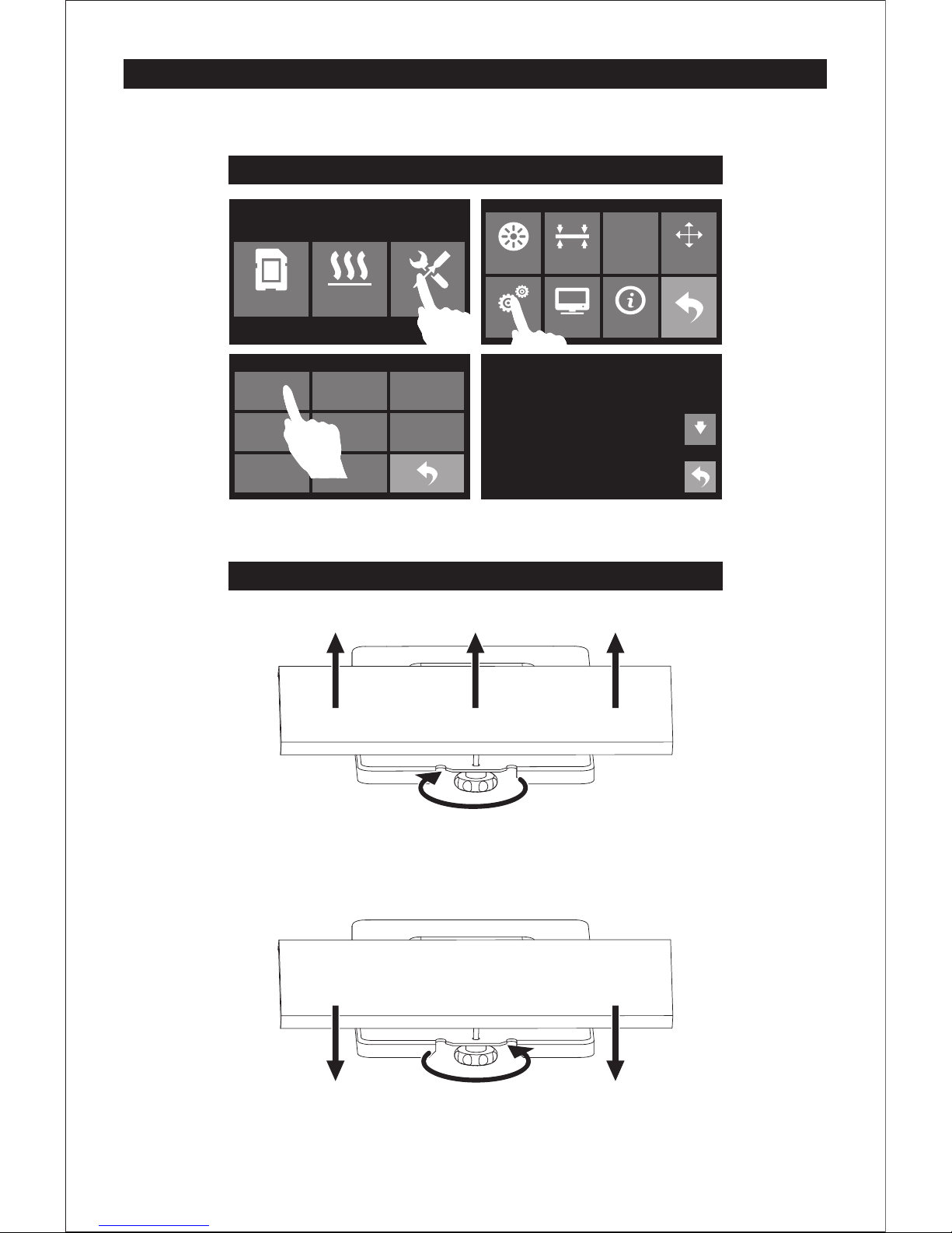
Leveling Build Plate
How to use the leveling knobs
Raise the build plate to reduce the distance between the nozzle and build plate.
Lower the build plate to increase the distance between the nozzle and build plate.
Rotate knob clockwise
Rotate knob anticlockwise
Print Preheat Tools
HOME
Filament Level Home Manual
Setting Status About
Language Fan On
FactoryReset
Update
WiFi
Pulley
简体中文
English
繁體中文
日本語
Deutsch
Resume Print
ON
How to change language
08
한국어
Camera
Page 10
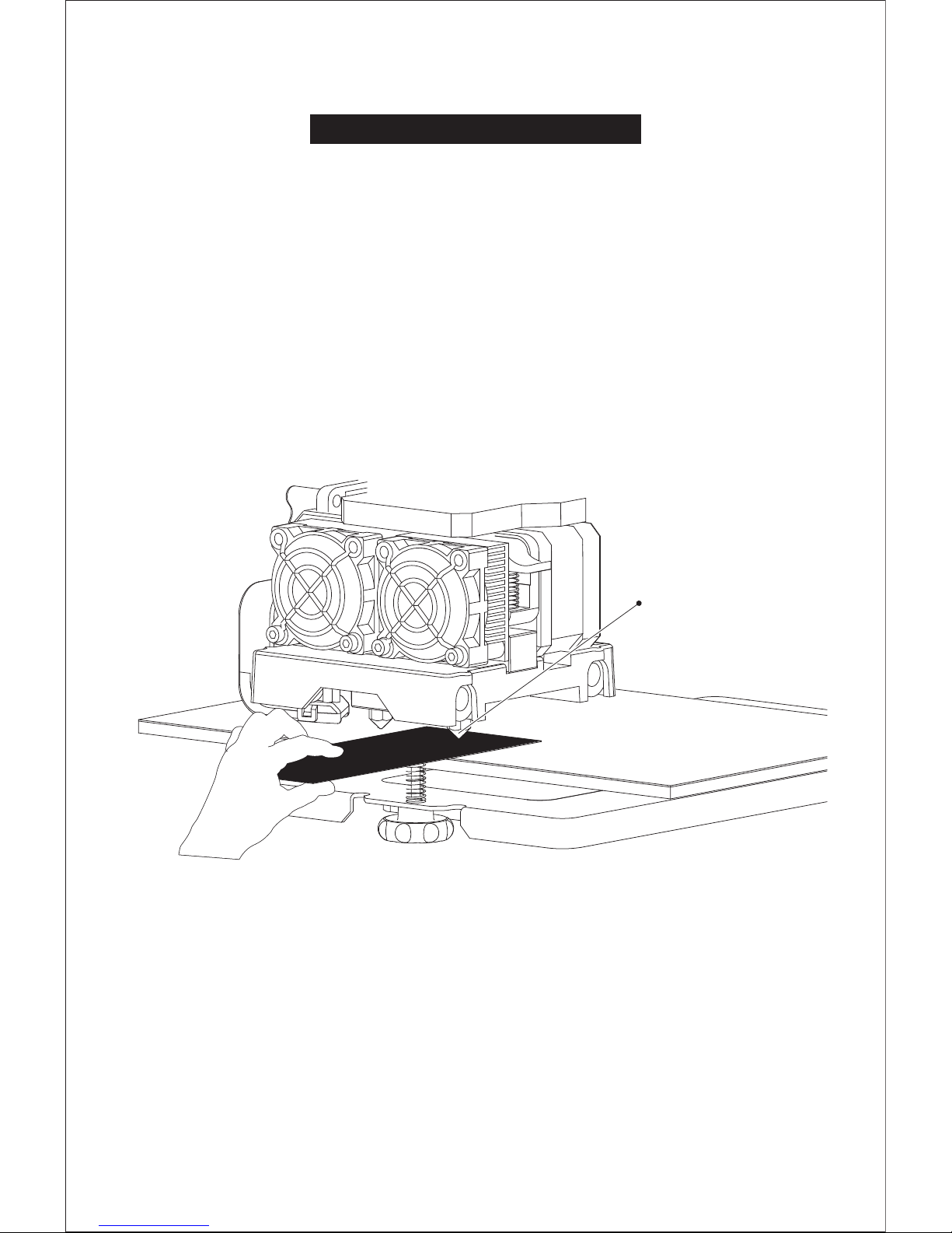
How to level the build plate
1. Tighten the three leveling knobs under the build platform until you cannot tighten them any more.
2. Tap [Tools], [Leveling] to start leveling.
3. The build plate and nozzle will start to move. Wait for them to stop, then adjust the corresponding knob
under the right nozzle first using the leveling card.
4. The leveling card should slide between the nozzle and build plate with some friction/resistance.
If the card slides through easily, the nozzle and build plate are too far apart. Rotate the knob clockwise to
decrease the distance between them. If the card cannot slide through, rotate the knob anticlockwise.
5. After leveling the first point, tap [OK] to continue to the next point.
6. Adjust all three knobs as outlined above. Then, check that the nozzle is also correctly placed when it is
at the center of the build plate, using the leveling card. That's it!
The distance should be that
between the right nozzle and
build plate.
09
Page 11
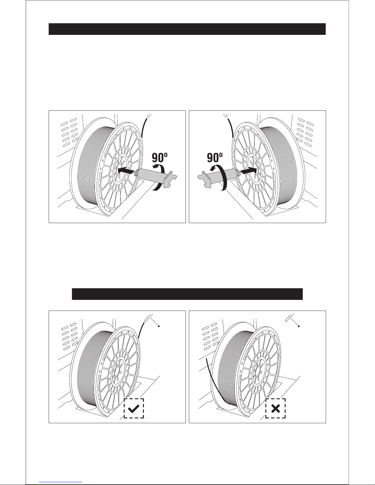
Place Filament and Loading Filament
1. Remove PLA filament from packaging.
2. Place filament in spool slots located on both sides of the printer.
3. As shown below, insert spool holder into the center hole of the filament. Rotate 90 degrees to
lock. To remove spool holder, rotate in the opposite direction.
Ensure filament is placed in spool slots with correct orientation.
Correct Direction
Wrong Direction
Guide Wire Guide Wire
10
Fixed the filament by left spool holder Fixed the filament by right spool holder
Page 12
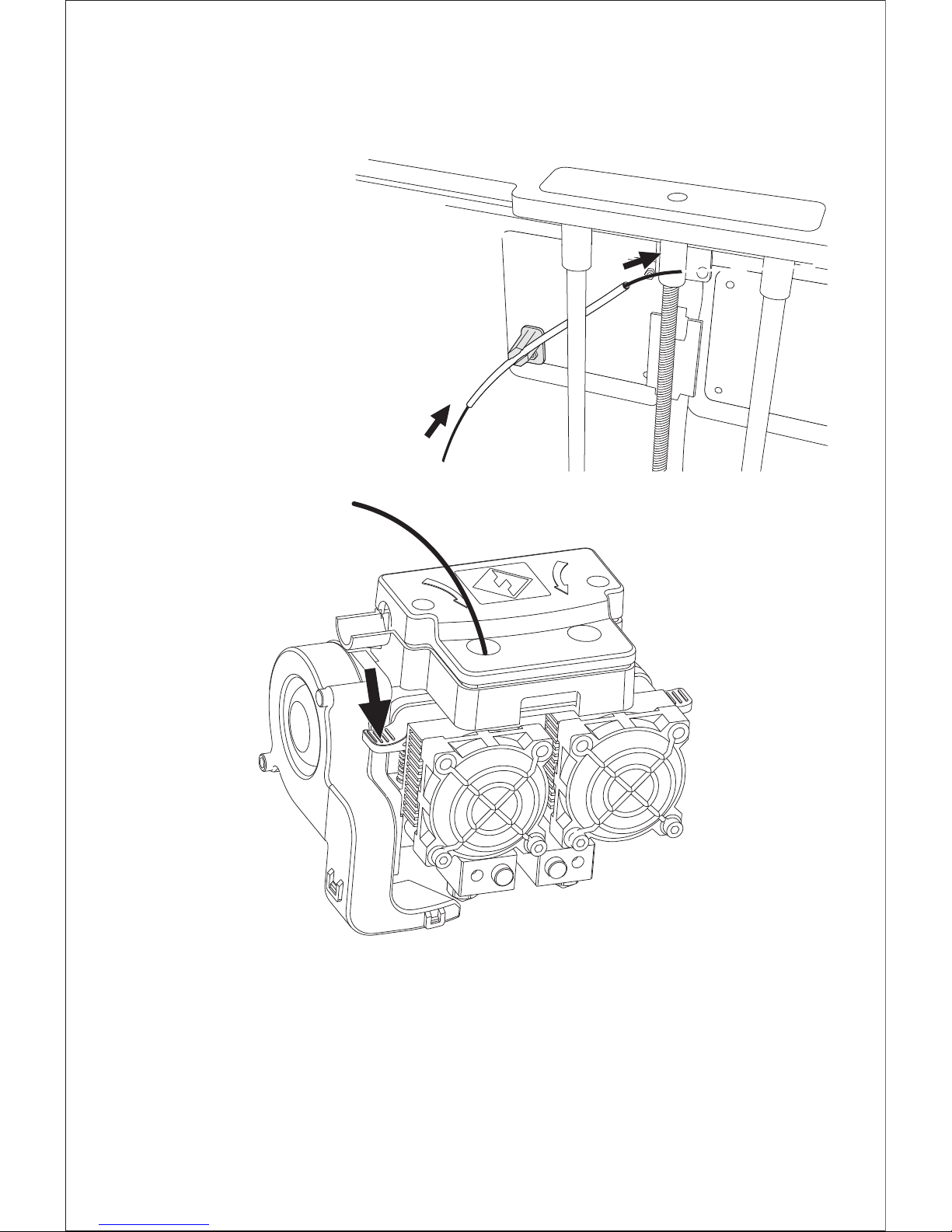
1. Tap the right icon labeled [Tools] button, then tap [Filament].
2. Select [Load Left].
3. Wait for the extruder to reach operating temperature. An alert will indicate this.
4. Secure the filament with a flat cross-section and load it by inserting the filament into the
extruder at an upright angle, meanwhile press down the spring presser.
5. Filament will flow out of the nozzle. Continue loading until the filament is extruded in a
straight line.
1. After filament placement, thread the filament
through guide tube.
2. Insert the filament into the left extruder at a
perpendicular angle while pressing down the
spring presser. Ensure the end of the filament
has a flat surface before loading it.
11
Page 13
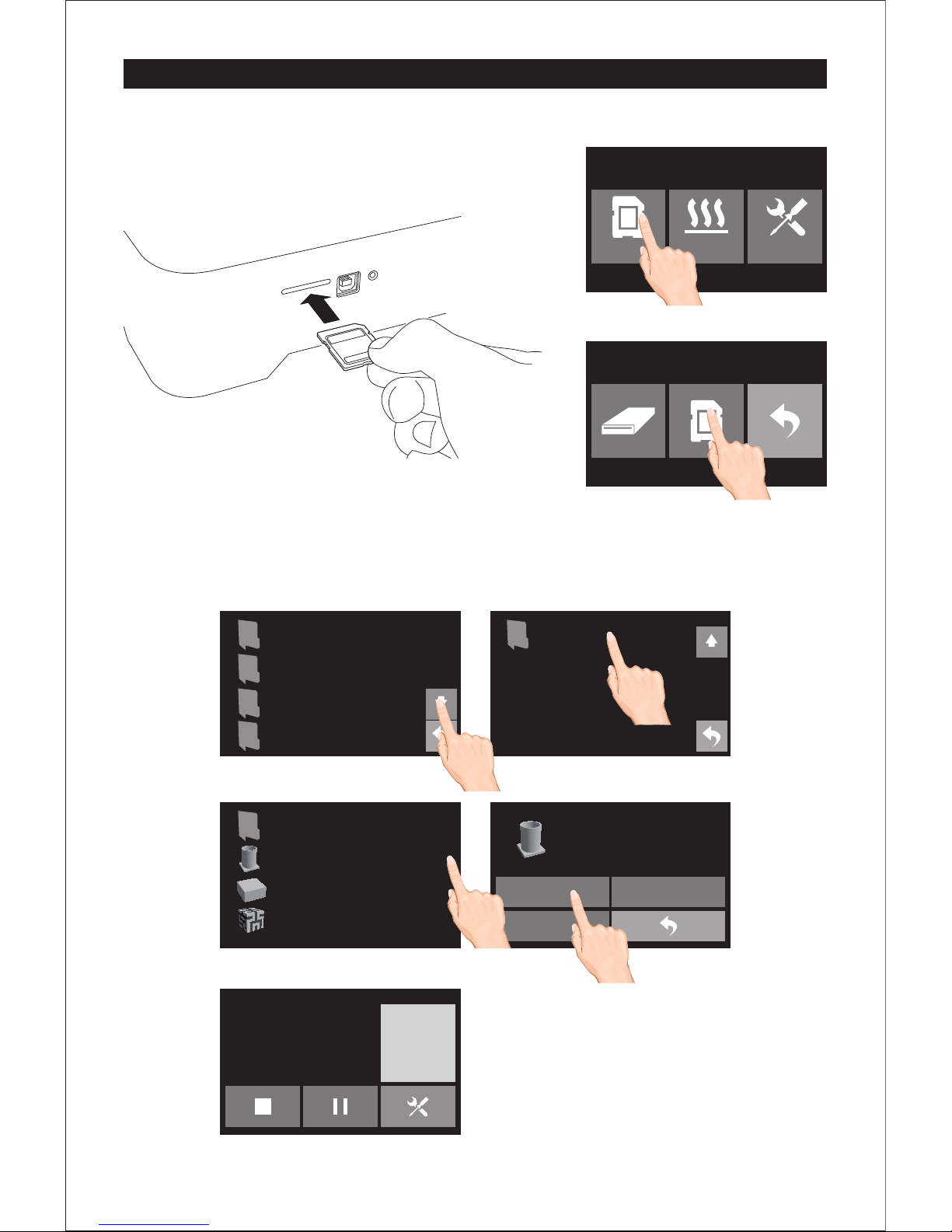
Print Preheat Tools
First Print
12
1. Insert SD card into SD card slot which is on the right side of printer.
2. Tap [Print]-[SD card], turn to next page, tap [Test Files],
click first 3D modeling file, and than tap [print]. Once heated, the printer will
start printing automatically.
F-Test left ex tr ud er -P LA
40mm_Box -l ef t ex tr ud er -P LA
Hilbert_ Cu be _a b- RL ex tr ud er-
Pri nt
Cop y
Del ete
Print Time: 1 :2 4
..
FlashP ri nt切 片软件
Inventor说 明书U se r Gu ide
测试文件Tes t Fi le s
Happy3 D 软件 安装 包 Software
Inventor快 速启 动指 南Quick St
F-Test left ex tr ud er -P LA
Pri nt Time
L Ext rud er
0:00
30℃
0%
R Ext ruder
Pla tform
30℃ / 50℃
30℃ / 20 0℃
F-Test left ex tr ud er -P LA
Page 14
Scan QR to Get More
After-Sales Support
Tel: +86 579 8227398 9 Web: www.flashforge.com Add: 2/F, No.5 18, Xianyuan Road, Jin hua, Zhejiang, China
After-Sales Service: [email protected]
 Loading...