

FLASHELEK JX 5600 User Manual
© FLASHELEK 2007 : 17 rue Marcel Sembat F-21000 DIJON
JX 5600
User manual
Release 1.24
This document is subject to modification without notice
Please, if necessary, ask for new release at : contact@flashelek.com
FLA
SH
EL
EK

2 / 22
Table of contents
1 Generals...................................................................................................................................................................3
1.1 Physical wiring.................................................................................................................................................3
1.2 Commanding the Flash sets ........................................................................................................................7
1.3 Querying the Flash sets.................................................................................................................................7
1.4 Case of J-Bus fault ..........................................................................................................................................7
2 Dialog with JX 5600 ..............................................................................................................................................8
3 Harware local mode ...............................................................................................................................................8
4 Ethernet mode........................................................................................................................................................9
4.1 Machine level ...................................................................................................................................................9
4.1.1 ASCII mode...............................................................................................................................................9
4.1.2 ModBus-Jbus mode............................................................................................................................... 11
4.1.2.1 Querying the JX5600......................................................................................................................... 11
4.1.2.2 Answer from the JX5600.................................................................................................................. 12
4.1.2.3 Error trapping..................................................................................................................................... 12
4.2 Human level .................................................................................................................................................. 13
4.3 Web site........................................................................................................................................................... 14
4.3.1 Index page............................................................................................................................................... 14
4.3.2 Maintenance of the JX 5600 ................................................................................................................ 15
4.3.3 Maintenance of the SFLS Clock Cards............................................................................................... 16
4.4 JX5600Mgr...................................................................................................................................................... 17
4.5 Recovering factory configuration............................................................................................................ 20
4.5.1 Using reset button ................................................................................................................................. 20
4.5.2 Entering parameters .............................................................................................................................. 21
3 / 22
1 Generals
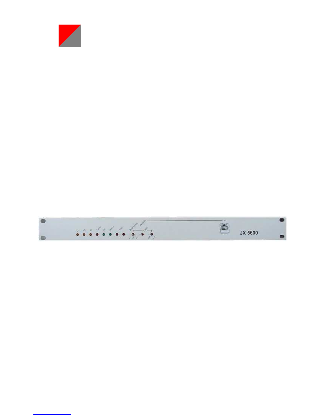
The JX 5600 set has to be used in conjonction either with JX 2360 or JX 2600 families Flash Light Power
Sets.
1.1
Physical wiring
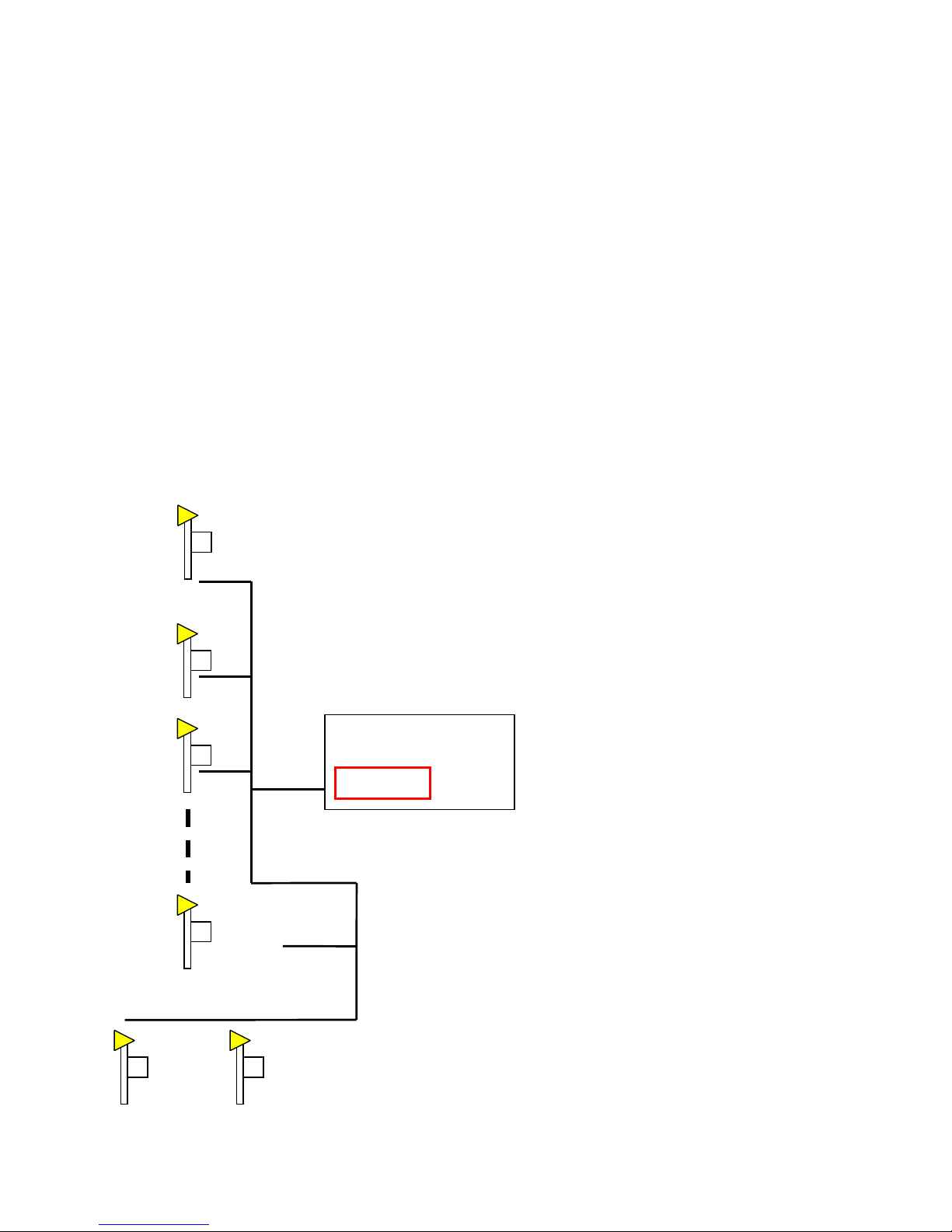
It is used to monitor and remote control a SFLS assembly such as described underneath :
The Power Station supplies the sets with main 240V AC +/- 10 % (Black wire on diagram).
The mains cable has to be able to supply 0,5 rms A (220 V AC) or 1 rms A (110 V AC) for each flash lamp.
This power supply is maintained continuously on line, as the eventual heater resistor may has to be supplied.
The JX 5600 will be in charge of switching On and Off the flashes.
Power Station
JX 5600

4 / 22
The sets are hierarchicaly sequenced via an unique analog time base line (clock signal, blue wire on diagram)
This signal passes through single shielded wire.
Each clock top is a 20Vpp pulse of 10 ms duration.
This flash is the Master.
His internal clock pilots the repetition
period of the whole SFLS
Power Station
JX 5600
This flash is the Master.
Its internal clock pilots the repetition
period of the whole SFLS.
It has to be set in factory
These 2 flashes are REILS.
They have no intervall delay and, by
the fact, flash always together as
one.
The R1, first in the sequence, has to
be set in factory.
5 / 22
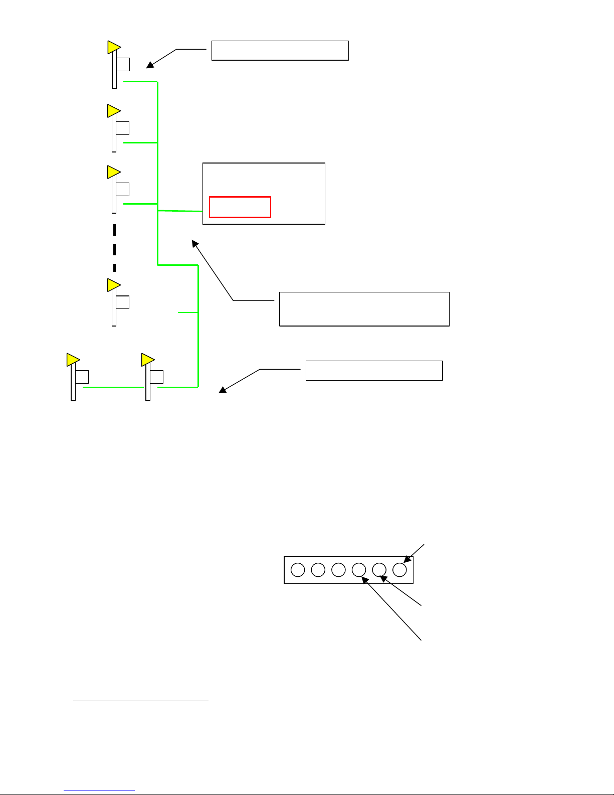
The sets are monitored and controled via a serie (RS485) digital bus called J-Bus (Green wire on diagram)
This bus is constructed with a shielded twist pair cable.
This bus allows JX 5600 to :
1.
Command the sets
2. Query the sets
JX 5600 Rear panel connector
(Jbus connections).
It is necessary to connect a J-Bus Load on each “end of line” to insure a perfect impedance for the digital
signal. 3 J-Bus Loads are delivered with eachJX 56001.
1
If you need spare parts do not hesitate to ask your reseller or contact@flashelek.com
Power Station
JX 5600
Connect a J-Bus
Load
here
Connect a J-Bus
Load
here
It is recommanded to insert a
« signal repeater » every 1 000 m
Connect to J-Bus B
Connect to J-Bus A
GND
6 / 22
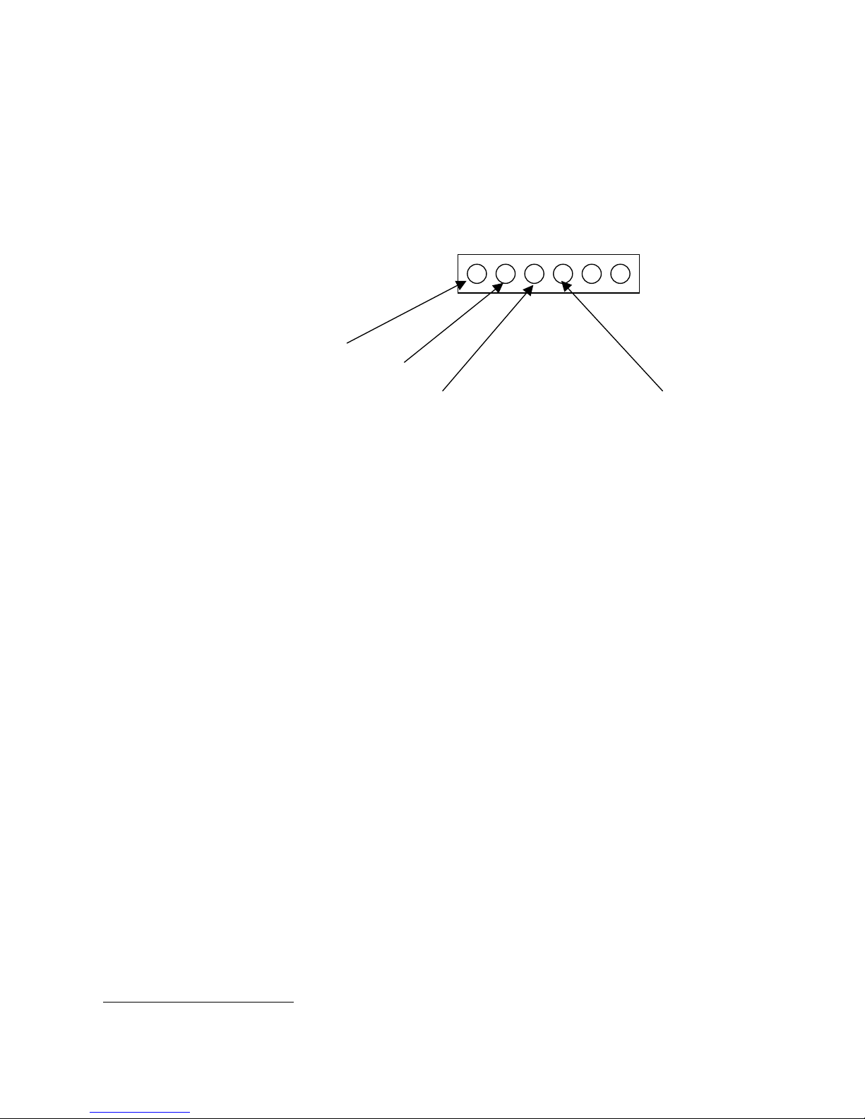
HI
MI
ON
GND
A “signal repeater”2 (symetrical amplifier) may be necessary when the line is longer than 1 000 m, even if a
1 600 m trial succeded.
The J-Bus lets the JX 5600 command the flash sets state and query sets infos.
It is also possible to command the set via analog way. (see JX2360 Connection manual for details)
JX 5600 Rear panel connector
(Analog connections).
To switch on the sets, short-circuit “ON” and “GND”
When ON, to change brilliance levels, short-circuit “MI” or “HI” and “GND”. If both are short-ciruited,
only “HI” is functionnal.
The total resistance of the short circuit have to be less than 125 Ohmx for a SFLS of 31 boxes
2
Ordered separately. Ask your reseller for details or send a mail at contact@flashelek.com

7 / 22
1.2
Commanding the Flash sets
The JX 5600 may :
• Switch on/off the sets
• Select brilliance level (3% low intensity : LI,
10% medium intensity : MI
100% hight intensity : HI)
If necessary, the JX 5600 may :
• Change the repetition period of the SFLS from 500 ms to 1 s , 1,5 s or 2 s.
• Change the inter flash intervall delay from 0, 14, 66 or 266 ms.
1.3
Querying the Flash sets
The JX 5600 may query the sets for:
• The present brightness set up
• Wether a lamp operates or not (curative maintenance)
• The number of flashes a lamp has done since the last global switch on (preventive maintenance)
• Internal un-documented technical datas
1.4
Case of J-Bus fault
When a box do not receive any J-Bus frame during a period longer than 2mn, then it automaticaly force
its internal J-Bus command to the state OFF/Low Intensity.
Analog commands keep their action.
 Loading...