

8 Amp Micro Stepping
Pro Series CNC Controller
Hardware Guide
Midwest Office
444 Lake Cook Road, Suite 22
Deerfield, IL 60015
Phone (847) 940-9305 Fax (847) 940-9315
www.flashcutcnc.com
Revised 11/02/2010
© 1998-2010 WPI, Inc.


Table of Contents
1. GETTING STARTED ....................................................................................................................................... 6
ABOUT THIS MANUAL ................................................................................................................................................ 6
TURNING OFF THE CONTROLLER ............................................................................................................................... 6
SAFETY AND USAGE GUIDELINES ............................................................................................................................... 7
2. STEPPER CNC CONTROLLER ..................................................................................................................... 8
FRONT PANEL............................................................................................................................................................. 8
REAR PANEL .............................................................................................................................................................. 9
3. SYSTEM CONNECTIONS ............................................................................................................................ 13
4. REMOVING THE TOP COVER ................................................................................................................... 14
5. SIGNAL GENERATOR ................................................................................................................................. 15
INPUT ................................................................................................................................................................ ....... 15
OUTPUT .................................................................................................................................................................... 16
JUMPER SETTINGS .................................................................................................................................................... 17
JP83 – DB to USB Ground ................................................................................................................................ 18
JP84/JP85 – Input Power Select ........................................................................................................................ 18
JP 86 – USB to Chassis Ground ........................................................................................................................ 19
JP 87 – Internal Signal to Chassis Ground ...................................................................................... 20
INTERNAL CONNECTIONS ......................................................................................................................................... 20
JP30 – Auxiliary Inputs ..................................................................................................................................... 21
JP31 – Status LEDs ........................................................................................................................................... 21
JP32 – Bus Expansion ....................................................................................................................................... 22
JP33 – Step & Direction .................................................................................................................................... 22
JP40 – Input Aux Header ................................................................................................................................... 23
JP50 – Output Aux Header ................................................................................................................................ 23
JP80 – Rear Panel Power .................................................................................................................................. 24
JP81 – Rear Panel Fuse .................................................................................................................................... 24
JP82 – Front Panel Switch .......................................................................................................... 24
AXIS PLUG-IN INTERFACES ...................................................................................................................................... 24
6. DRIVE SETTINGS .......................................................................................................................................... 26
CONFIGURING THE DRIVES ....................................................................................................................................... 27
Selecting a Motor............................................................................................................................................... 27
Setting the Current ............................................................................................................................................. 29
Setting Idle Current ............................................................................................................................................ 29
Load
Inertia ........................................................................................................................................................ 30
Step Size ................................................................................................................................... 30
STEP PULSE NOISE FILTERING .................................................................................................................................. 32
SELF TEST ................................................................................................................................................................ 33
ALARM CODES ......................................................................................................................................................... 33
7. MOTOR SIGNAL SETTINGS ....................................................................................................................... 34
8. STEPPER MOTOR CABLING ..................................................................................................................... 35
MOTOR WIRING FOR OTHER STEPPER MOTORS ....................................................................................................... 35
9. POWER BOARD ............................................................................................................................................. 37
10. DRIVER MODULE UPGRADES .................................................................................................................. 39
11. APPENDIX ....................................................................................................................................................... 45
SAMPLE WIRING DIAGRAMS .................................................................................................................................... 45
Typical Output Line Circuit ............................................................................................................................... 45
Typical Input Line Circuit – Internal Power ...................................................................................................... 46
Typical Input Line Circuit – External Power ................................................................ ................................ ..... 47

Signal Generator Board Layout ......................................................................................................................... 49
Connector Pin-Out Table ............................................................................................................ 50
POWER ..................................................................................................................................................................... 52
OUTPUTS .................................................................................................................................................................. 53
INPUTS ..................................................................................................................................................................... 54
CONNECTORS ........................................................................................................................................................... 55
AXIS PLUG-IN INTERFACE ........................................................................................................................................ 56
12. INTERNAL CONNECTIONS ........................................................................................................................ 57
CONNECTION SCHEMATIC ........................................................................................................................................ 58
REVISION HISTORY .................................................................................................................................................... 1


6
1. Getting Started
Always turn off the CNC Controller when it is not in use.
About This Manual
FlashCut CNC is a unique application involving hardware and software. We
recommend that you read all of these instructions before using the product.
Since automated machining is potentially dangerous, please take
the time to completely read through this manual and the software
User’s Guide to understand the operation of the electronics,
software and machine before cutting a part.
FlashCut CNC Section 1 Getting Started
Turning Off The Controller

FlashCut CNC Section 1 Getting Started
7
When running an automated machine tool, safety is of the utmost
importance. For proper and safe use of the FlashCut CNC program and
your CNC machine, the following safety guidelines must be followed:
1. Never let the machine tool run unattended.
2. Require any person in the same room as a running machine tool to
wear safety goggles, and to stay a safe distance from the machine.
3. Allow only trained operators to run the machine tool. Any operator
must have:
Knowledge of machine tool operation.
Knowledge of personal computer operation.
Knowledge of Microsoft Windows.
Good common sense.
4. Place safety guards around the machine to prevent injury from flying
objects. It is highly recommended that you build a safety shield
around the entire tool envelope.
5. Never place any part of your body within the tool envelope while the
machine is online, since unexpected machine movement can occur at
any time.
6. Always keep the tool envelope tidy and free of any loose objects.
7. Be on alert for computer crashes at all times.
FlashCut CNC, Inc. is not responsible for the safe installation and use of
this product. You and only you are responsible for the safety of yourself
and others during the operation of your CNC machine tool. FlashCut CNC
supplies this product but has no control over how it is installed or used.
Always be careful!
FlashCut CNC, Inc. or its affiliates are not responsible for damage to any
equipment or workpiece resulting from use of this product.
If you do not understand and agree with all of the above safety guidelines,
do not use this product.
Safety and Usage Guidelines
FlashCut CNC Section 2 Stepper CNC Controller
8
2. Stepper CNC Controller
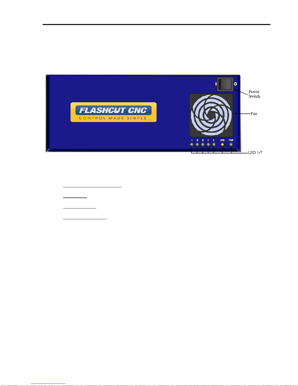
Front Panel
The front panel of the CNC controller has the power switch, the fan and 7 LED’s with the
following functions:
AXIS LED’s 1, 2, 3, 4, 5 – Turns green when the respective axis is moving.
USB LED– Turns yellow when connected to the host PC USB port.
POWER LED– Turns green when the power switch is turned on.
POWER SWITCH – Turns the unit on and off. “I” is on and “O” is off. If there is ever a
communications error while running FlashCut CNC, turn the switch off and on to reset
the internal microprocessor.
9
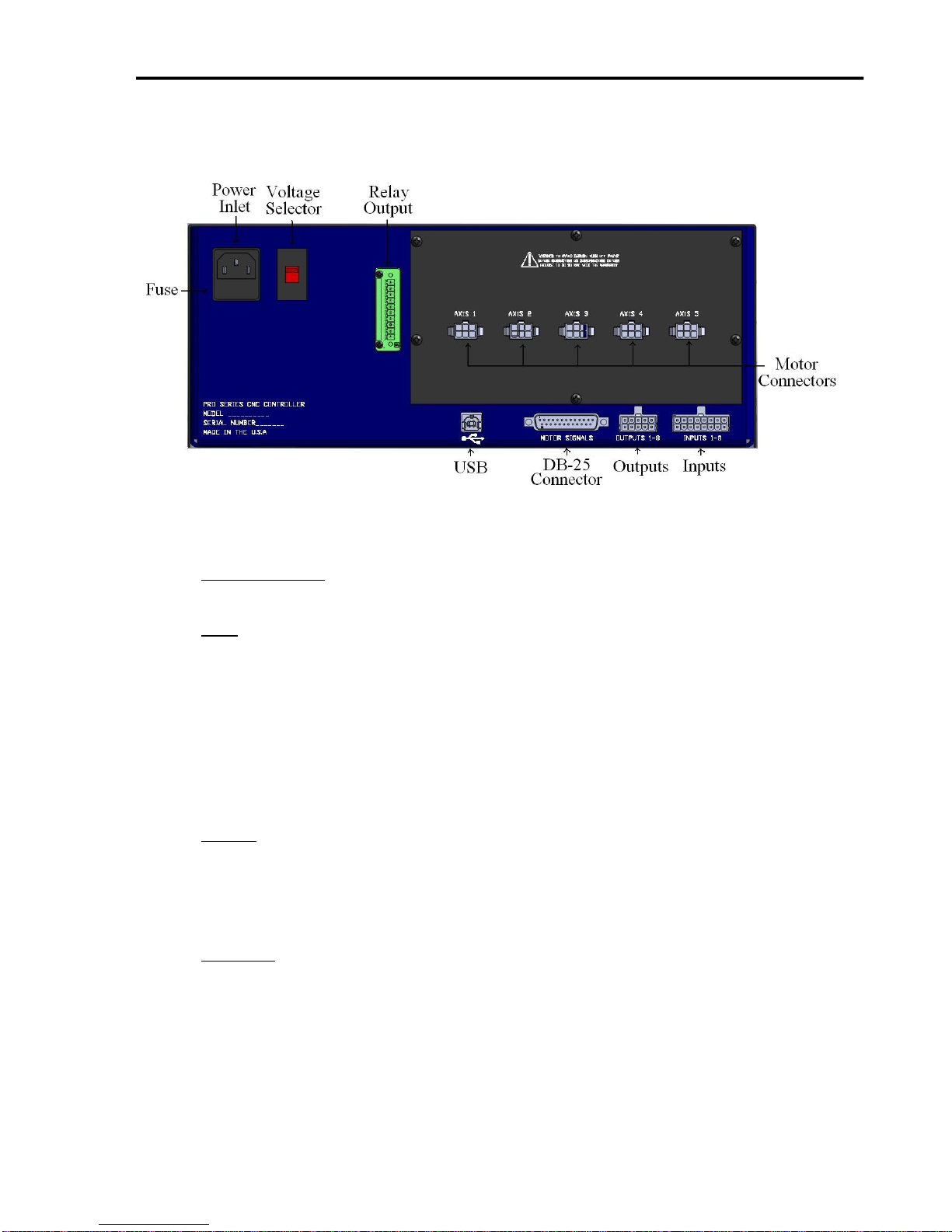
Rear Panel
The rear panel has connectors for input and output signals as described below.
FlashCut CNC Section 2 Stepper CNC Controller
POWER INLET – Receptacle for the power supply. The unit is shipped with a standard
grounded power cable for use with a 115VAC wall outlet.
USB – USB connector for communication with the USB port on the host PC. Use a USB-A
to B cable with a maximum length of 3 meters to make the connection. For the most robust
communication, plug the cable directly into PC, as opposed to a USB repeater or a hub. If
the FlashCut software loses communication with the Signal Generator, electrical noise may
be the cause. To reduce electrical noise problems, try using a shorter USB cable, or attach
one or more ferrite chokes to the USB cable. Toroid-shaped chokes are more effective than
snap-on cylindrical chokes. If you need more than 3m of USB cable length, you can use an
active extension cable which comes in 4.5m lengths. Note that when running an active
extension cable, the USB will run in Full Speed mode.
INPUT – The connector for up to 8 input lines. The most common use of the input lines
is for limit or safety switches. These lines are all TTL- and CMOS-compatible optically
isolated inputs. When a switch is open, its input signal is high (+5V). When the switch is
closed, its input signal is grounded low (0V). If you need more than 8 input lines, an I/O
extension board is available.
OUTPUT – The connector for up to 8 output lines. These lines are all compatible with
TTL/CMOS level outputs. The Output ports are not setup to drive a 24V external system
unless it accepts TTL/CMOS levels. They are all driven by HCT family logic. Output
logic high is normally 5V and can go down to 3.9V at full load. Output logic low is
normally 0V and can go up to 0.3V at full load. Each of these signals can provide up to
20mA of current. If you need more than 8 output lines, an I/O extension board is
available.
FlashCut CNC Section 2 Stepper CNC Controller
10
FUSE – In this drawer is a 250V/ 10Amp slow blow fuse. If you have chronic fuse
problems, please call FlashCut CNC or your distributor for assistance.
RELAY OUTPUT – This connector is a back compatible relay output. Connection
should be made in pins 7 and 8 of the 10 pin Phoenix terminal block. Output provides an
optically isolated switch closure for controlling both AC and DC devices. Max current
loading is 0.5 Amps for this non-polarity sensitive connection.
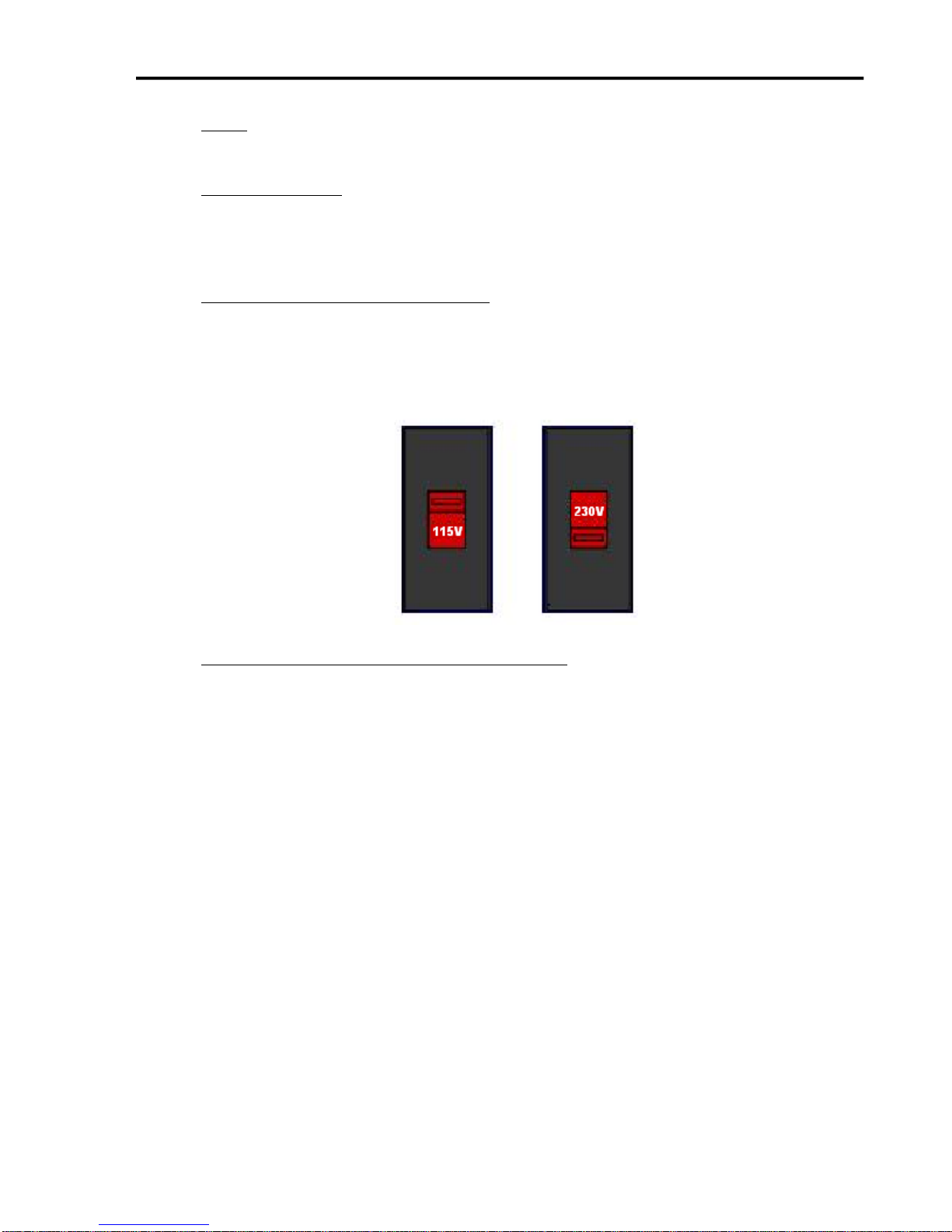
115-230 VAC SELECTION SWITCH– This switch allows you to use an external power
source of 115 or 230 VAC. If your building is wired for 230VAC, then simply flip the
switch with a flat-head screwdriver so that “230V” is clearly visible. If your building is
wired for 115 VAC, then flip the switch until “115V” is clearly visible. Note that severe
damage can occur if you have 115 selected and your building is wired for 230VAC.
DB-25 CONNECTOR FOR MOTOR SIGNALS – This uses a DB-25 Cable to send step
and direction signals from the FlashCut CNC Signal Generator to an additional external
drive box. The pin assignments are as follows:
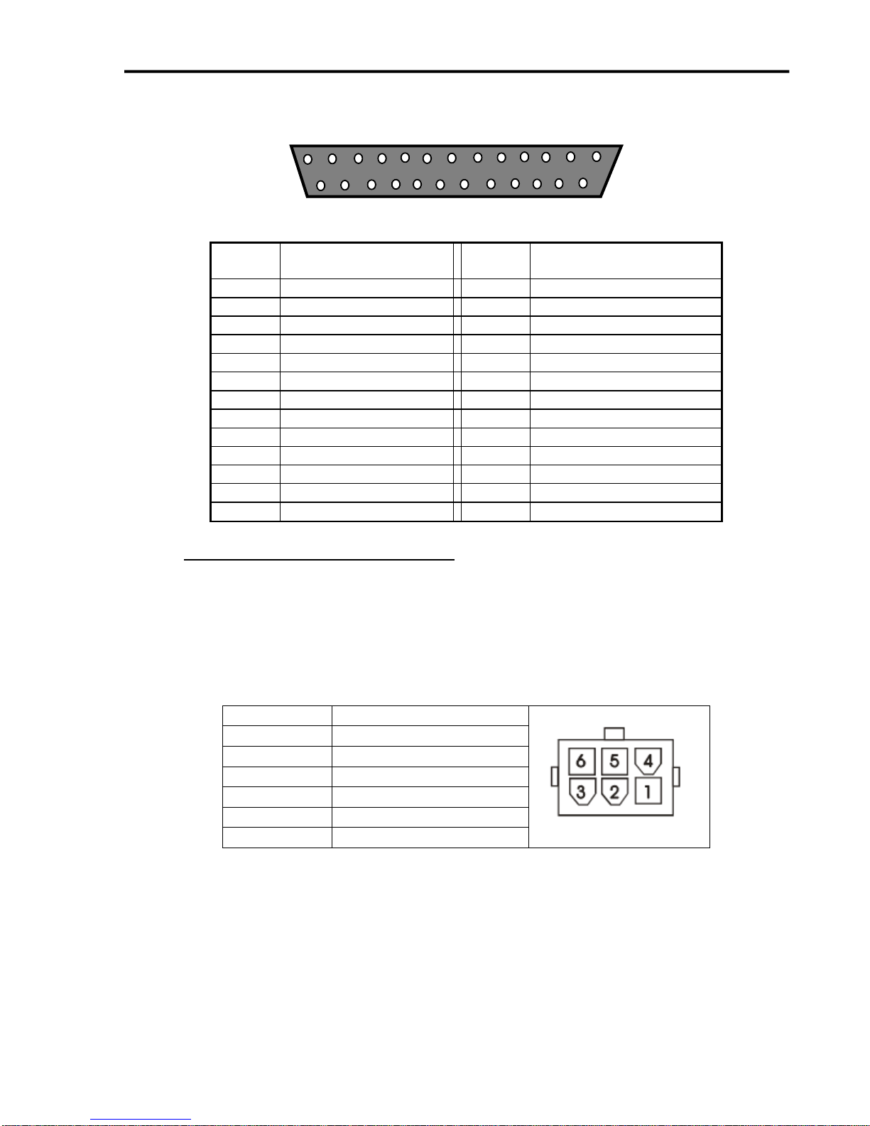
FlashCut CNC Section 2 Stepper CNC Controller
11
1
13
14
25
DB25
Pin No.
Signal
DB25
Pin No.
Signal
1
OUTPUT 1
14
ENABLE ALL
2
OUTPUT 2
15
INPUT 1
3
STEP AXIS 5
16
INPUT 2
4
DIRECTION AXIS 5
17
INPUT 3
5
INPUT 5
18
INPUT 4
6
INPUT 6
19
DIRECTION AXIS 4
7
INPUT 7
20
DIRECTION AXIS 3
8
INPUT 8
21
DIRECTION AXIS 2
9
DIRECTION AXIS 1
22
Internal VCC +5V
10
STEP AXIS 4
23
OPT VCC (INPUT)
11
STEP AXIS 3
24
Internal GND
12
STEP AXIS 2
25
OPT GND (INPUT)
13
STEP AXIS 1
Molex Pin
Wire
1 B 2
Cable Ground Shield
3 A 4
B~ 5 No Connection
6
A~
POWER CONNECTOR TO MOTORS – The motors for axes 1-5 plug into these
connectors. The motor lines 1-5 are correlated to any combination of the X, Y, Z, A
and/or B axes in the Motor Signal Setup menu in the FlashCut CNC software. A dummy
plug as installed on any unused motor connector for units with less than 5 axes. Each
motor connector is a Molex Mini Fit Jr. 6 Pin Receptacle with Male Pins (See Section on
Motor Cabling for Mating Connector Information). The pin assignments for the Motor
Connector are as follows (looking from the rear of the unit):

FlashCut CNC Section 2 Stepper CNC Controller
12
Never connect or disconnect motor cables while the power
is on. This will result in damage to the driver box.
The mating motor cable connector is a Molex - Waldom 6-Pin Mini-Fit Jr. Receptacle Housing
Part # 39-01-2060 with Female Pins Part # 39-00-0039 or 39-00-0047. Please see the section on
Stepper Motor Cabling later in this manual for more information.
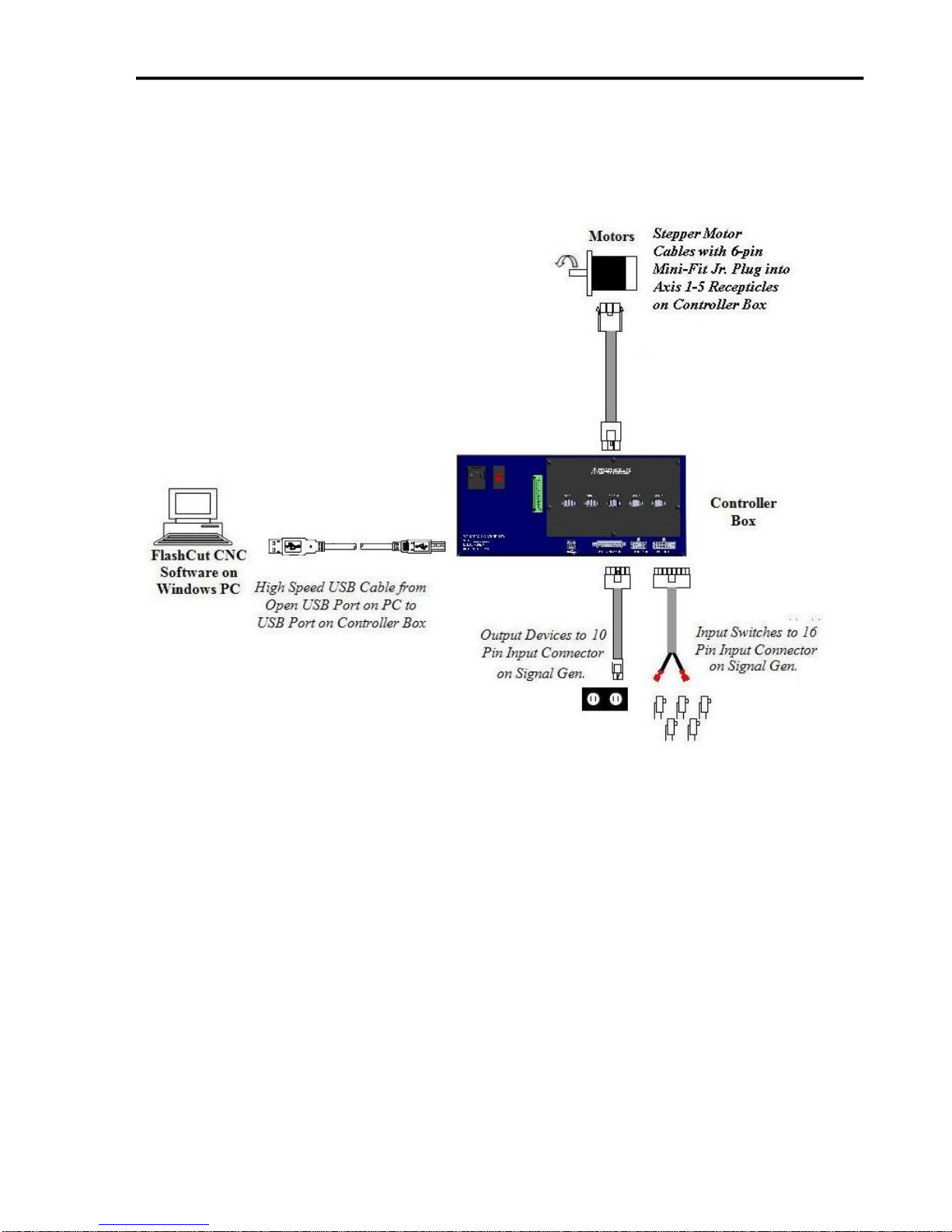
FlashCut CNC Section 3 System Connections
13
3. System Connections
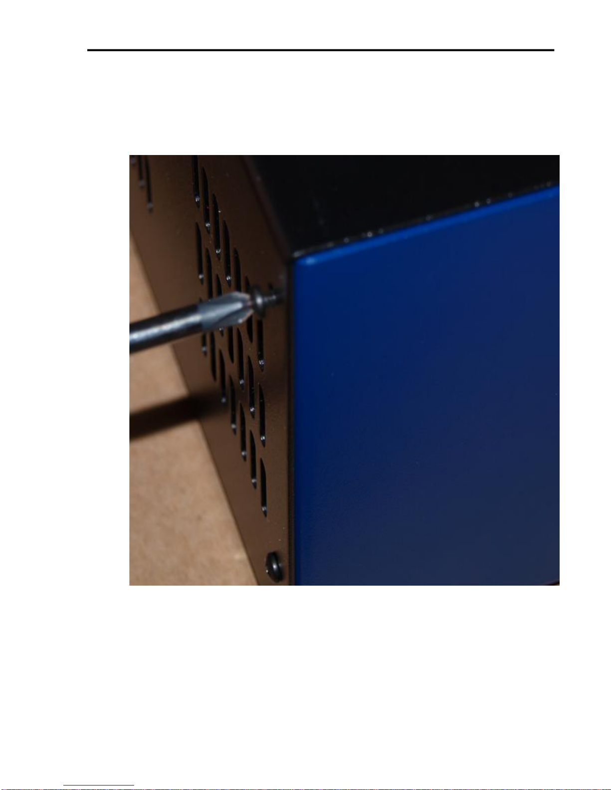
FlashCut CNC Section 4 Removing the Top Cover
14
4. Removing the Top Cover
To remove the cover from the unit remove the 8 total screws located on the left and right
sides of the unit. There are 4 screws on either side. Then lift the top cover off.

FlashCut CNC Section 5 Signal Generator
15
5. Signal Generator
Input
The default setting for each of the input lines is normally closed (NC). The input line
settings can be individually changed between normally closed (NC) or normally open
(NO) input lines using FlashCut CNC software. Please refer to the FlashCut CNC
User’s Guide under “Input Line Settings” for further information.
In the FlashCut CNC software, the Input Line Status dialog displays "OPEN" for a
high-level input voltage, or open switch, and "CLOSED" for a low-level input voltage
or closed switch.
The input lines are all optically isolated. Jumpers J84 and J85 enable you to choose
between the internal power of the Signal Generator and isolated power from an
external source. Both jumpers must be set on the same pair of pins (either both must
be on pins 1 and 2 or both must be on pins 2 and 3).
Internal Power- This is the most convenient option and works well for most
applications, but negates some of the signal isolation. When JP84 shorts pins 1
and 2, OPT VCC gets its power from the Internal 5V power source. When JP85
shorts pins 1 and 2, OPT GND is directly connected to the Internal GND.
External Isolated Power
For the best noise immunity, connect an external 5V-24V power supply to the
LED side of the optical couplers. When JP84 shorts pins 2 and 3, OPT VCC gets
its optically isolated power from the TB-VCC. When JP85 shorts pins 2 and 3,
OPT GND is directly connected to the TB-GND.
Choose only one of the following methods to supply power:
1. Connect a power source to the TB 40 screw terminal.
2. Connect a power source through pins 23 and 25 of the DB-25 connector.
If you are providing an external voltage through pins 23 and 25 of the DB25
Motor Signal connector or via TB-40, then you must have both JP84 and
JP85 jump pins 2 and 3, OTHERWISE SEVERE DAMAGE COULD
RESULT.
BE VERY CAREFUL WHEN DOING ANY WIRING. IMPROPER
WIRING WILL DAMAGE THE SIGNAL GENERATOR.
Input lines 1, 2, 3 & 4 are also connected through pins 15, 16, 17 & 18 respectively of
the Motor Signal connector, and input lines 5, 6, 7 & 8 are also connected through
pins 5, 6, 7 & 8 respectively of the Motor Signal connector. This makes it convenient
to send any signals from an external motor driver box, such as limit lines or servo
position error signal, back to the Signal Generator through the DB25 cable without
FlashCut CNC Section 5 Signal Generator
16
Mini-Fit Jr.
Pin No.
Signal
Mini-Fit Jr.
Pin No.
Signal
1
OPT-GND
9 INPUT 1
2
OPT-GND
10
INPUT 2
3
OPT-GND
11
INPUT 3
4
OPT-GND
12
INPUT 4
5
OPT-GND
13
INPUT 5
6
OPT-GND
14
INPUT 6
7
OPT-GND
15
INPUT 7
8
OPT-GND
16
INPUT 8
16 15 14 13 12 11 10 9
◦ ◦ ◦ ◦ ◦ ◦ ◦ ◦
◦ ◦ ◦ ◦ ◦ ◦ ◦ ◦
8 7 6 5 4 3 2 1
using a separate input cable. Note that if an input line is being used through the
Motor Signal connector, that line must remain open in the Input connector.
The receptacle that plugs into this connector is a Molex-Waldom Mini-Fit Jr. Series
16 pin receptacle (part number 39-01-2160), with female pins (part number 39-000039 or 39-00-0047 for 22 gauge or thinner wires).
The Molex 63811-1000 for 14-24 AWG universal or Molex 11-01-0197 Crimp Tools
are recommended for installing the pins. Kits containing connectors and pins are
available through FlashCut CNC or an electronics distributor.
The input lines as seen from the back of the box are arranged as follows (all
connections denoted by “OPT-GND” are optically isolated ground.):
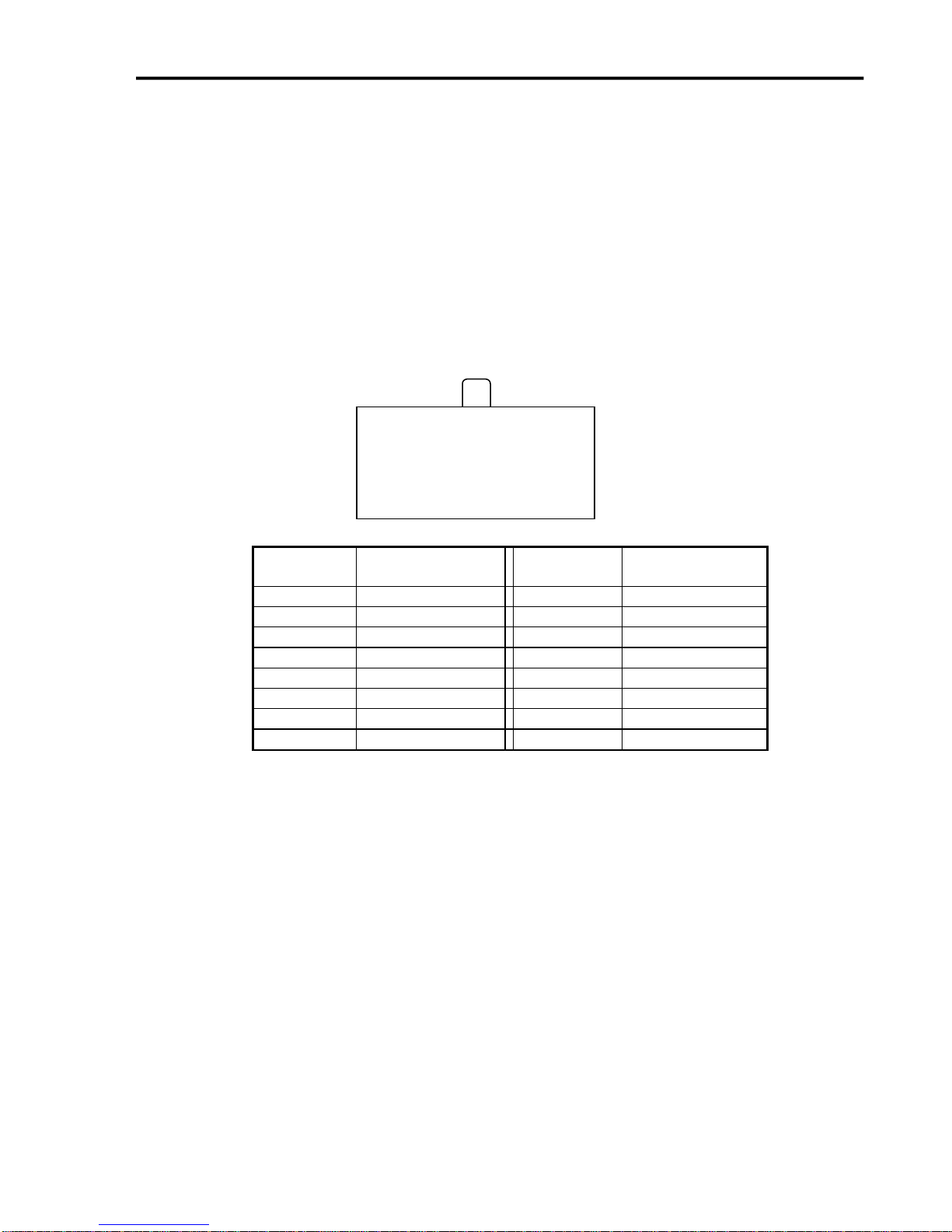
Output
This connector is for up to 8 output lines. These lines are all compatible with
TTL/CMOS level outputs. The Output ports are not setup to drive a 24V external
system unless it accepts TTL/CMOS levels. They are all driven by HCT family
logic. Output logic high is normally 5V and can go down to 3.9V at full load.
Output logic low is normally 0V and can go up to 0.3V at full load. Each of these
signals can provide up to 20mA of current.
Two additional pins on this connector are provided for your output lines: ground and
+5V. These are connected to GND and +5V and are not optically isolated. This 5V
circuit can source up to 100 mA. Any larger current demand would require a larger
power source.
FlashCut CNC Section 5 Signal Generator
17
Mini-Fit Jr.
Pin No.
Signal
Mini-Fit Jr.
Pin No.
Signal
1
OUTPUT 1
6 OUTPUT 2
2
OUTPUT 3
7 OUTPUT 4
3
OUTPUT 5
8 OUTPUT 6
4
OUTPUT 7
9 OUTPUT 8
5
+5V
10
GROUND
10 9 8 7 6
◦ ◦ ◦ ◦ ◦
◦ ◦ ◦ ◦ ◦
5 4 3 2 1
BE VERY CAREFUL WHEN DOING ANY WIRING. IMPROPER WIRING
WILL DAMAGE THE SIGNAL GENERATOR.
The output lines are all initialized to low (0V) when you turn on the Signal
Generator. Output lines 1 and 2 are also connected through pins 1 and 2 respectively
of the Motor Signal connector. This makes it convenient to connect up to 2 output
signals to an external motor driver box to drive devices such as solid-state relays that
might be in an external motor driver box.
The receptacle that plugs into this connector is a Molex-Waldom Mini-Fit Jr. Series
10 pin receptacle (part number 39-01-2100), with female pins (part number 39-000039 or 39-00-0047 for 22 gauge or thinner wires).
The Molex 63811-1000 for 14-24 AWG universal or Molex 11-01-0197 Crimp
Tools are recommended for installing the pins. Kits containing connectors and pins
are available through FlashCut CNC or an electronics distributor.
The output lines as seen from the back of the box are arranged as follows:
Jumper Settings
Pin 1 of all jumpers is indicated by a small white dot printed on the PCB.
FlashCut CNC Section 5 Signal Generator
18
JP83 – DB to USB Ground
This connects the DB 25 ground to the USB ground. By default pins 1 and 2, 3 and
4, and 5 and 6 are jumped as pairs
.
JP84/JP85 – Input Power Select
These two jumpers enable you to choose between the internal power of the Signal
Generator and isolated power from an external source. Both jumpers must be set on
the same pair of pins (either both must be on pins 1 and 2 or both must be on pins 2
and 3).
Internal Power
This is the most convenient option and works well for most applications, but
negates some of the signal isolation. When JP84 shorts pins 1 and 2, OPT VCC
gets its power from the Internal 5V power source. When JP85 shorts pins 1 and
2, OPT GND is directly connected to the Internal GND.

FlashCut CNC Section 5 Signal Generator
19
DB25 PIN22
DB25 PIN23
DB25 PIN24
DB25 PIN25
TB40
OPT-GRD
TB-VCC
OPT-VCC
TB-GRD
+5V
1
2
3
JP84
VCC
JP85
GRD
1
2
3
2
1
DB25 PIN22
DB25 PIN23
DB25 PIN24
DB25 PIN25
OPT-GRD
TB-VCC
OPT-VCC
TB-GRD
+5V
1
2
3
JP84
VCC
JP85
GRD
3
2
1
External Isolated Power
For the best noise immunity, connect an external 5V-24V power supply to the
LED side of the optical couplers. When JP84 shorts pins 2 and 3, OPT VCC
gets its optically isolated power from the TB-VCC. When JP85 shorts pins 2
and 3, OPT GND is directly connected to the TB-GND.
Choose only one of the following methods to supply power:
1. Connect a power source to the TB 40 screw terminal.
2. Connect a power source through pins 23 and 25 of the DB-25 connector.
3. Check the resistor value in RP41 to make sure it matches the voltage in
TB40.
If you are providing an external voltage through pins 23 and 25 of the
DB25 Motor Signal connector or via TB-40, then you must have both JP84
and JP85 jump pins 2 and 3, OTHERWISE SEVERE DAMAGE COULD
OCCUR.
JP 86 – USB to Chassis Ground
This jumper connects the USB shield to the chassis ground of the Signal Generator
when jumped.
TB40 Voltage RP41 Value (10 pin 9 Resistor SIP)
5V 3.9k (Default)
12V 11k
24V 22k

20
FlashCut CNC Section 5 Signal Generator
JP 87 – Internal Signal to Chassis Ground
This jumper connects the internal signal ground to the chassis ground of the Signal
Generator when jumped.
Internal Connections
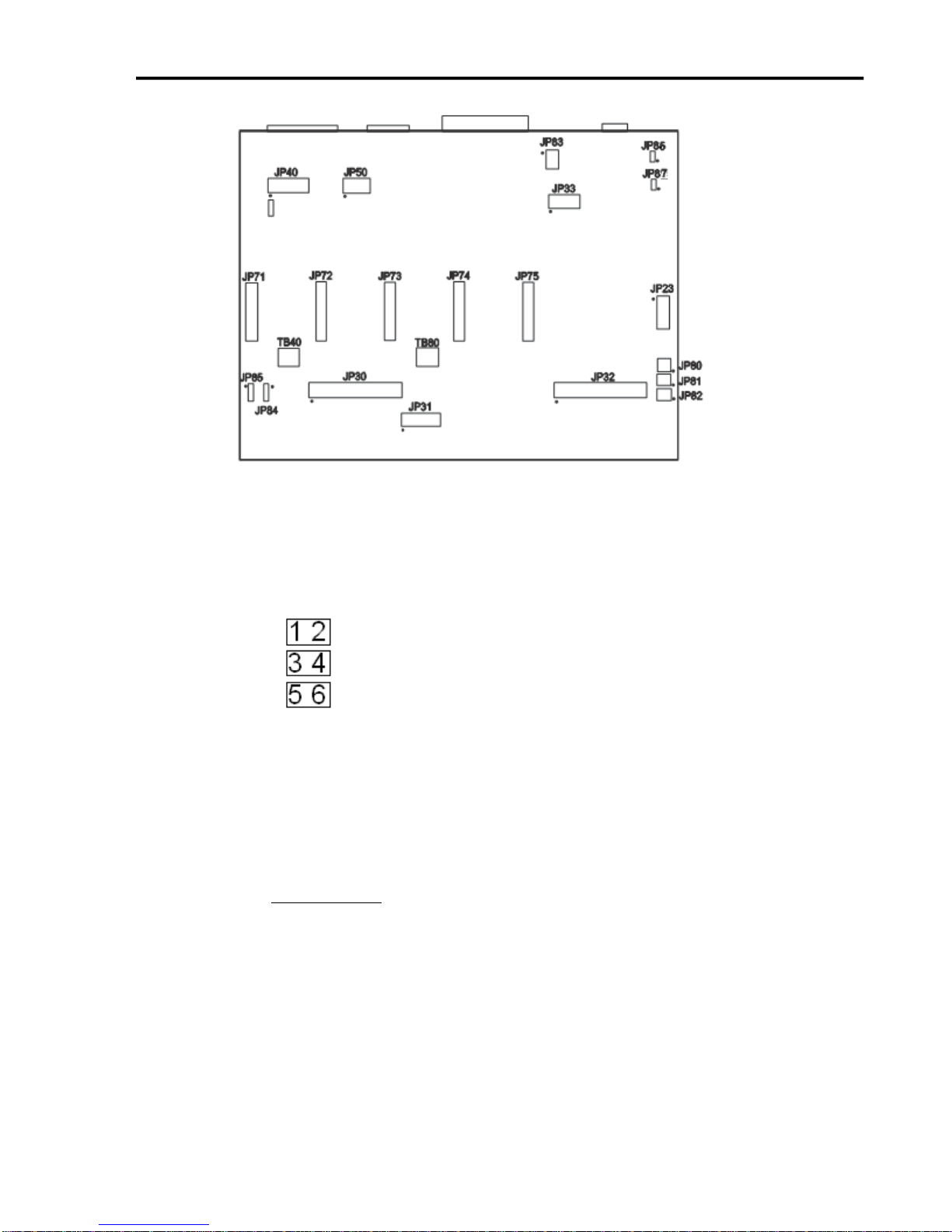
The diagram below shows the locations of the internal connectors. The top of the
diagram corresponds to the back side of the signal generator (where the external
connectors are located). The small dot next to some of the connectors designates
the number 1 pin position.
On the following diagrams, the positions of the connectors will be highlighted in
black.
Connectors JP30, JP31, JP32, JP33

21
This contains all of the Input
Signals 1-8 which come out of
the 501A board and Input
Signals 9-32 which come out
of the I/O Expansion board.
+3.3V
1 2 +3.3V
GPI32
3 4 GPI1
GPI31
5 6 GPI2
GPI30
7 8 GPI3
GPI29
9
10
GPI4
GPI28
11
12
GPI5
GPI27
13
14
GPI6
GPI26
15
16
GPI7
GPI25
17
18
GPI8
GND
19
20
GND
GPI24
21
22
GPI9
GPI23
23
24
GPI10
GPI22
25
26
GPI11
GPI21
27
28
GPI12
GPI20
29
30
GPI13
GPI19
31
32
GPI14
GPI18
33
34
GPI15
GPI17
35
36
GPI16
+3.3V
37
38
+3.3V
GND
39
40
GND
This is for connecting wired
LEDs from a custom chassis
to the 501A LED signals.
+5V
1 2 N/C
LED-DIR1
3 4 LED-STEP1
LED-DIR2
5 6 LED-STEP2
LED-DIR3
7 8 LED-STEP3
LED-DIR4
9
10
LED-STEP4
LED-DIR5
11
12
LED-STEP5
LED-AUX
13
14
LED-USB
GND
15
16
LED-PWR
FlashCut CNC Section 5 Signal Generator
JP30 – Auxiliary Inputs
JP31 – Status LEDs

FlashCut CNC Section 5 Signal Generator
22
This contains signal and
address lines for the I/O
Expansion board.
+3.3V
1 2 GND
CS6
3 4 STATUS6
TXD2
5 6 FAULT6
RXD2
7 8 AUX1-STB
OUT-ENA
9
10
AUX2-STB
OUT2-STB
11
12
OUT1-STB
OUT4-STB
13
14
OUT3-STB
+5V
15
16
+5V
GND
17
18
GND
A0
19
20
A1
DATA1
21
22
DATA2
DATA3
23
24
DATA4
DATA8
25
26
DATA7
DATA6
27
28
DATA5
+7V
29
30
+7V
SPHOME
31
32
ENC CLK
+3.3V
33
34
ENC DIR
AGND
35
36
AV+
DAC2
37
38
DAC1
ADC1
39
40
AGND
This contains all of the step
and direction signals for 5
axes of motion.
STEP5
1 2 ENA
STEP4
3 4 DIR5
STEP3
5 6 DIR4
STEP2
7 8 DIR3
STEP1
9
10
DIR2
GND
11
12
DIR1
JP32 – Bus Expansion
JP33 – Step & Direction

FlashCut CNC Section 5 Signal Generator
23
This contains the same
signals as the Mini-Fit Jr.
Input Connector. It is
provided for the convenience
of using a different input
connector or an external input
connector on a custom
chassis.
GPI1
1 2 OPT-GND
GPI2
3 4 OPT-GND
GPI3
5 6 OPT-GND
GPI4
7 8 OPT-GND
GPI5
9
10
OPT-GND
GPI6
11
12
OPT-GND
GPI7
13
14
OPT-GND
GPI8
15
16
OPT-GND
This contains the same
signals as the Mini-Fit Jr.
Input Connector. It is
provided for the convenience
of using a different input
connector or an external input
connector on a custom
chassis.
GPO2
1 2 GPO1
GPO4
3 4 GPO3
GPO6
5 6 GPO5
GPO8
7 8 GPO7
GND
9
10
VCC
Connectors JP40, JP50
JP40 – Input Aux Header
JP50 – Output Aux Header

FlashCut CNC Section 5 Signal Generator
24
Connectors JP80, JP81, JP82
JP80 – Rear Panel Power
Connect the main power here. It can be 8.5V – 16V DC or AC. See
current draw chart for power requirements.
JP81 – Rear Panel Fuse
This is for an optional power fuse. The unit is shipped with a shunt
instead of a fuse. If you replace the shunt with a fuse, it should be sized
according to your power requirements.
JP82 – Front Panel Switch
Connect the main power switch here.
Axis Plug-In Interfaces
Axis Plug-Ins JP71 – JP75

FlashCut CNC Section 5 Signal Generator
25
1 2
3 4
5 6
7 8
9 10
11 12
13 14
15 16
17 18
19 20
Each of these plug-in cards is a SKT10X2 connector, with the
pin configuration on the left. Pin numbers 1-5, 7, 13, 15 and
17-20 perform the same function on each jumper.
Per the chart below, pins 6, 8-12, 14 and 16 have different
values of Status, Fault, InputA, Dir, InputB, Step, SCOM and
CS respectively for each plug-in card.
Pin
No.
Label
Function
JP-71
JP-72
JP-73
JP-74
JP-75
1
HV-PWR
High Voltage Power
HV-PWR
HV-PWR
HV-PWR
HV-PWR
HV-PWR
2
HV-PWR
High Voltage Power
HV-PWR
HV-PWR
HV-PWR
HV-PWR
HV-PWR
3
GND
Ground
GND
GND
GND
GND
GND
4
GND
Ground
GND
GND
GND
GND
GND
5
RxD2
Serial Com. Receive
RxD2
RxD2
RxD2
RxD2
RxD2
6
STATUS
Status
STATUS1
STATUS2
STATUS3
STATUS4
STATUS5
7
TxD2
Serial Com. Transmit
TxD2
TxD2
TxD2
TxD2
TxD2
8
FAULT
Fault Indicator
FAULT1
FAULT2
FAULT3
FAULT4
FAULT5
9
INPUTA
Input A
IN8
IN10
IN12
IN14
IN16
10
DR
Direction
DR1
DR2
DR3
DR4
DR5
11
INPUTB
Input B
IN9
IN11
IN13
IN15
IN17
12
ST
Step
ST1
ST2
ST3
ST4
ST5
13
SM0
SM0
SM0
SM0
SM0
SM0
SM0
14
SCOM
SCOM
SCOM1
SCOM2
SCOM3
SCOM4
SCOM5
15
SM1
SM1
SM1
SM1
SM1
SM1
SM1
16
CS
Chip Select
CS1
CS2
CS3
CS4
CS5
17
ENA
Enable
ENA
ENA
ENA
ENA
ENA
18
+5V
+5V
+5V
+5V
+5V
+5V
+5V
19
GND
GND
GND
GND
GND
GND
GND
20
GND
Ground
GND
GND
GND
GND
GND
The Axis plug-in interfaces are used to add additional functions to the main signal
generator board. For example, a stepper drive plug-in card or cable will enable
you to drive a stepper motor directly from the signal generator box.

FlashCut CNC Section 6 Drive Settings
26
6. Drive Settings
Inside of the controller box are the individual drive modules for axes 1-5.
Each drive module has Logic Connector for the Step, Direction, COM and Enable signals
coming from the Axis Plug-in connector on the Signal generator, a Motor Connector for
the A and B Coils of the motor, a Power Connector, and a group of DIP Switches for
configuring the drive for your specific requirements. The configuration of the DIP
switches vary depending on your application.

FlashCut CNC Section 6 Drive Settings
27
Configuring the Drives
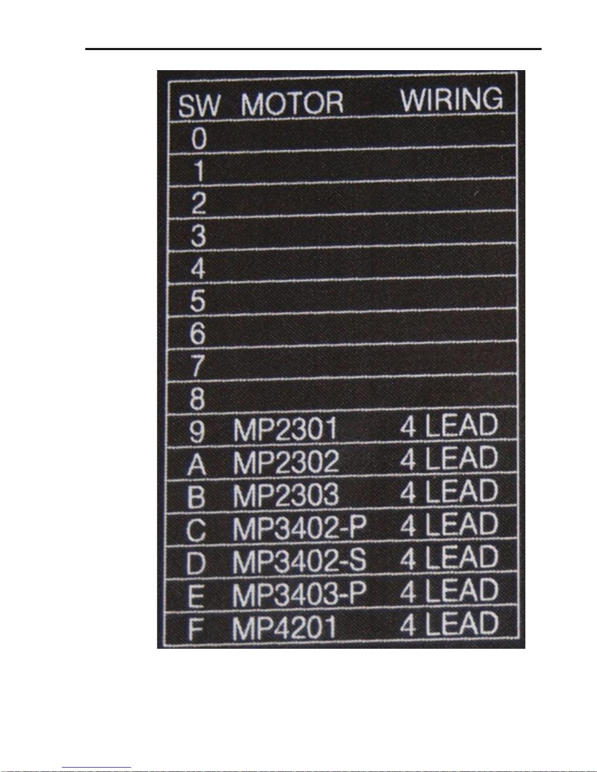
Selecting a Motor
The drives are optimized for use with selected variety of stepper motors.
Each setting matches the current and inertia of a given motor providing the
most power with minimum resonance. To select a motor, simply move the
rotary switch to the letter or number that corresponds to the motor of your
choice. Make sure the power is off before changing this setting, or damage
could occur to your motor or drive.
If your motor is not on the list please set the switch to a selection whose rotor
inertia, holding torque and current are within 10% of your motor.
FlashCut CNC Section 6 Drive Settings
28

FlashCut CNC Section 6 Drive Settings
29
Setting the Current
The maximum current for the motor you have selected is set automatically
when you set the rotary switch. But you may want to reduce the current to
save power or lower motor temperature. This is important if the motor is not
mounted to a surface that will help it dissipate heat or if the ambient
temperature is expected to be high.
Step motors produce torque in direct proportion to current, but the amount of
heat generated is roughly proportional to the square of the current. If you
operate the motor at 90% of rated current, you’ll get 90% of the rated torque.
But the motor will produce approximately 81% as much heat. At 70%
current, the torque is reduced to 70% and the heating to about 50%.
Two of the small switches on the front of the drive are used to set the percent
of rated current that will be applied to the motor: SW1 and SW2. Please set
them according to the illustration below. The factory default setting is 70%.
Setting Idle Current
Motor heating and power consumption can also be reduced by lowering the
motor current when it is not moving. The drive will automatically lower the
motor current when it is idle to either 50% or 90% of the running current.
The 50% idle current setting will lower the holding torque to 59%, which is
enough to prevent the load from moving in most applications. This reduced
motor heating by 75%. In some applications such as those supporting a
vertical load, it is necessary to provide a high holding torque. In such cases,
the idle current can be set to 90% as shown below. The default setting is for
50% idle current.

FlashCut CNC Section 6 Drive Settings
30
Load
Inertia
The drives include anti-resonance and electronic damping features which
greatly improve motor performance. To perform optimally, the drive must
understand the electromechanical characteristics of the motor and load. Most
of this is done automatically when you select the motor by setting the rotary
switch. To further enhance performance you must set a switch to indicate the
appropriate inertia ratio of the load and motor. The ranges are 0 to 4X and 5
to 10X. Simply divide the load inertia by the rotor inertia to determine the
ratio, then set switch 3 accordingly, as shown.
Step Size
The drive module requires a source of step pulses to command motion. This
may be a PLC, an indexer, a motion controller or another type of device. The
only requirement is that the device be able to produce step pulses whose
frequency is in proportion to the desired motor speed, and be able to
smoothly ramp the step speed up and down to produce smooth motor
acceleration and deceleration.
Smaller step sizes result in smoother motion and more precise speed, but also
require a higher step pulse frequency to achieve maximum speed. The
smallest step size of the drives is 1/20,000th of a motor turn while the
maximum step rate of the signal generator is typically between 50,000 and

FlashCut CNC Section 6 Drive Settings
31
100,000 steps/sec.Six different settings are provided in the drive module, as
shown in the table below. Please choose the one that best matches the
capabilities for your system.
At lower step resolutions such as 200 steps/revolution (full step) and 400
steps/revolution (half step), motors run a little rough and produce more
audible noise than when they are microstepped (2000 steps/revolution and
beyond). The drives include a feature called “microstep emulation”, also
called “step smoothing”, that can provide smooth motion from coarse
command signals. If you select “200 SMOOTH or 400 SMOOTH”, this
feature is automatically employed to provide the smoothest possible motion
from a less than ideal signal source.
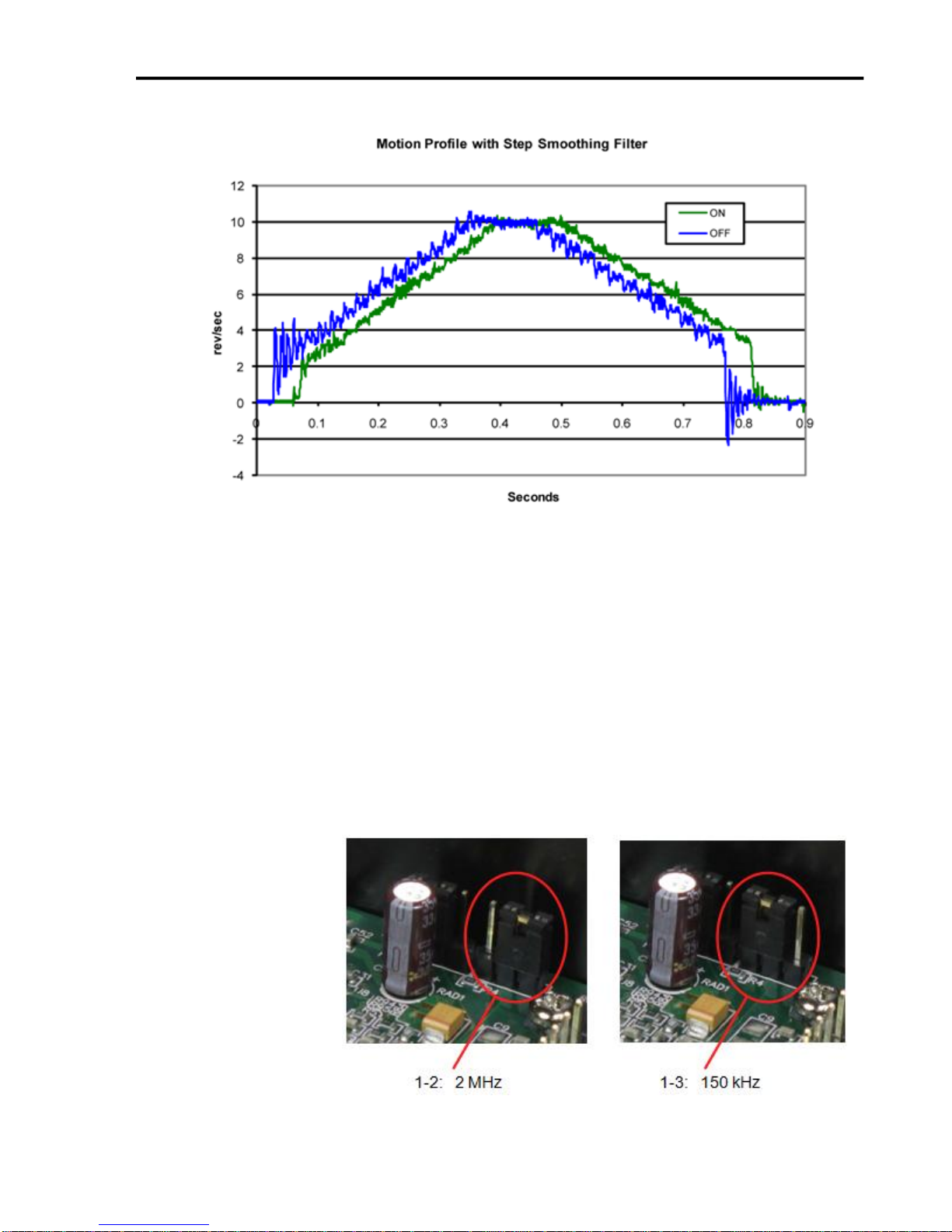
Because a command filter is used as part of the step smoothing process, there
will be a slight delay, or “lag” in the motion. If this delay is objectionable for
your application, please choose the non-filtered setting “200” or “400”. The
chart on the next page shows an example of the delay that can occur from
using the step smoothing filter. If you are using the smoothing feature, you
must have all axis in the same smoothing mode, otherwise there will be a
timing problem with multi-axis interpolation.
FlashCut CNC Section 6 Drive Settings
32
Step Pulse Noise Filtering
Electrical noise can affect the STEP signal in a negative way, causing the
drive to think that one step pulse is two or more pulses. This results in extra
motion and inaccurate motor and load positioning. To combat
this problem the drives include a digital noise filter on the STEP and DIR
inputs. The default factory setting of this filter is 150 kHz, which works well
for most applications.
However as discussed in “Step Size” of this section, if you are operating the
drive module at a high number of steps/revolution and at high motor speeds
you will be commanding the drive at step rates above 150 kHz. In such cases
you should remove the cover and move jumper S4 from the 150 kHz position
(1-3) to the 2 MHz position (1-2) as shown
below.

33
.
Self Test
FlashCut CNC Section 6 Drive Settings
Your maximum pulse rate will be the highest motor speed times the
steps/revolution. For example, 40 revolutions/second at 20,000
steps/revolution is 40 X 20,000 = 800 kHz. Please consider this when
deciding if you must increase the filter frequency,
If you are having trouble getting your motor to turn you may want to try the
built-in self test. Anytime switch 8 is moved to the ON position, the drive
will automatically rotate the motor back and forth, two turns in each
direction. This feature can be used to confirm that is correctly wired, selected
and otherwise operational.
Alarm Codes
In the event of a drive fault or alarm, the green LED will flash one or two
time, followed by a series of red flashes. The pattern repeats until the alarm
is cleared.

FlashCut CNC Section 7 Motor Signal Settings
34
7. Motor Signal Settings
The motor settings in the Motor Signal Setup Screen in the FlashCut CNC software need
to be properly set according to the driver box that you have. Please refer to Motor Signal
Setup section of the User’s Guide for the best way to set up your drive for your software
version.
For this drive, the best signals are as follows:
Driver Model: 8A Pro Micro Stepper (6501-X-080-M
Step Pulse: High
Step Pulse Width: 5
Min. Time Between Steps: 5
Direction-Step Setup: 5
Min. Step-Direction Lag: 5
Enable Signal Polarity: High

FlashCut CNC Section 8 Stepper Motor Cabling
35
Molex Pin
Motor Wire
1 B 2
Cable Ground Shield
3
A
4
B~
5
No Connection
6
A~
8. Stepper Motor Cabling
Motor Cable - 2 Twisted pair (one pair for A coil and one pair for B Coil) 22 gauge and
shielded (18 gauge for 6A motors). Shield is only connected to noted pin on MolexWaldom connector and should not be connected to motor end. Use Belden - M 8723 CM
2PR22 Shielded Cable or equivalent.
Connector - Molex - Waldom 6-Pin Mini-Fit Jr.
Receptacle Housing Part # 39-01-2060.
Female Pins Part # 39-00-0039 or 39-00-0047
Motor Wiring for Other Stepper Motors
If you have your own stepper motor, you can use the following charts for your
wiring. Note that the motor wire colors will vary.

FlashCut CNC Section 8 Stepper Motor Cabling
36
A to A~
About 1-10 ohms (Equal to B to B~)
B to B~
About 1-10 ohms (Equal to A to A~)
A or A~ to B or B~
No Continuity
A Center to A or A~
½ the resistance of A to A~
B Center to B or B~
½ the resistance of B to B~
B Center to A or A~
No Continuity
A Center to B or B~
No Continuity
6 Lead Motor – ½ Coil Bipolar 6 Lead Motor – Series Bipolar
8 Lead Motor – Parallel Bipolar 8 Lead Motor – Series Bipolar
Unknown Motor Wiring
If you are uncertain which is the A pair and which is the B pair, you can use an
ohm meter and the following chart to determine the pairs (and the center taps on a
6- wire motor)
If the A and A~ or the B and B~ are reversed, the motor will spin the opposite
direction. This can easily be corrected by changing the motor polarity in the
Setup…Motor Settings menu in the FlashCut CNC software.

37
9. Power Board
FlashCut CNC Section 9 Power Board
The function of the Power Board is to supply DC voltage to the drive modules as well
as to the cooling fan and logic signals to the Signal Generator. The power enters the
board in the form AC voltage from a transformer; the AC voltage is then converted to DC
voltage. The Power Board also contains the indication LED’s:
AXIS LED’s 1, 2, 3, 4, 5 – Turns green when the respective axis is moving.
USB LED– Turns yellow when connected to the host PC USB port.
POWER LED– Turns green when the power switch is turned on.
LOGIC AC INPUT- This connector takes in the power from the transformer for the logic
signals. The AC voltage from the transformer is then converted to a DC voltage to be
used for logic signals. The two contacts are labeled as follows: L is the hot, N is the
neutral.
MOTOR AC INPUT- This connector takes in the power from the transformer for the
drive modules. The AC voltage from the transformer is then converted to a DC voltage
of 40-80V, depending on the connection configuration, to be used for powering the drive

FlashCut CNC Section 9 Power Board
38
+5V
1 2 N/C
LED-DIR1
3 4 LED-STEP1
LED-DIR2
5 6 LED-STEP2
LED-DIR3
7 8 LED-STEP3
LED-DIR4
9
10
LED-STEP4
LED-DIR5
11
12
LED-STEP5
LED-AUX
13
14
LED-USB
GND
15
16
LED-PWR
modules. The three contacts are labeled as follows: R is the reserve, L is the hot, N is the
neutral. The reserve and the hot may be switched to vary the voltage. For example if R is
red and L is purple the resulting DC voltage is approximately 67 VDC, where if R is
purple and L is red the resulting DC voltage is approximately 80 VDC.
SIGNAL GENERATOR DC OUTPUT- This output sends a 9 VDC signal to power the
Signal Generator. When viewing the power board in the configuration above the top
contact of the signal generator DC output is positive and the bottom contact is negative.
FAN DC OUTPUT- This output sends a 24 VDC signal to power the fan for cooling the
box. When viewing the power board in the configuration above the top contact of the fan
DC output is positive and the bottom contact is negative.
MOTOR DC OUTPUT- This output sends a 40-80 VDC, depending on the connection
configuration, DC signal to power the drive modules. Power for up to 5 individually
powered drive modules. The contacts alternate positive and negative starting with
positive on the contact nearest the large capacitor.
LED INPUT- This input receives logic signal from the signal generator in order to
illuminate any of the 7 LED’s indicating axis movement, power or USB connectivity.
The contact connections for the LED input are as follows:
JP31 – STATUS LEDS
2 X 8 - 2MM SPACING

FlashCut CNC Section 10 Driver Module Upgrades
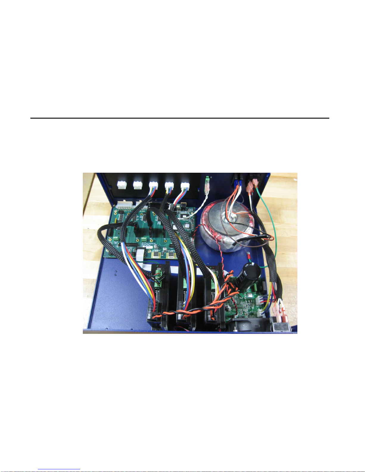
39
10. Driver Module Upgrades
To upgrade your CNC controller such as adding a 4th or 5th axis you should install the
new drive module(s) using the following instructions.
Improper wiring can cause damage to your driver box and/or motors. Please take
care in following these instructions properly. Please refer to the drawings below for
the correct logic connectors.
1. Set the Dip Switches to the appropriate settings for your application (default settings
pictured).

FlashCut CNC Section 10 Driver Module Upgrades
40
2. Mount the drive module to the driver box chassis using (2) 6-32 conducting screws.

FlashCut CNC Section 10 Driver Module Upgrades
41
3. Connect the power cable from the power board into V- and V+ on the drive making
sure to note polarity.

FlashCut CNC Section 10 Driver Module Upgrades
42
4. Connect the wires from the motor receptacle to the drive module motor connector
labeled B-, B+,A- and A+ on the drive module.

FlashCut CNC Section 10 Driver Module Upgrades
43
To properly ground your motor cable shield, connect Pin 2 of the motor cable
directly to the base of the drive module using the 6-32 hold down screw.

FlashCut CNC Section 10 Driver Module Upgrades
44
5. Connect the step, direction, enable and fault lines from the drive module to the signal
generator via the axis plug-in interface located on the PCB.
FlashCut CNC Section 11 Appendix
45
11. Appendix
Sample Wiring Diagrams
Typical Output Line Circuit
Signal Generator Model 501A
So lid State Relay
Continen tal In d u stries
S5 0 5-0SJ610-000
+ 3
Load
1
2
AC
Fuse
3.3K
4
OPT
GND
Output1
74ACT16373DL
Q8
U50A
Q1
Q4
Q6
Q7
Q5
Q3
Q2
GPO7
GPO6
GPO5
GPO4
GPO3
GPO2
GPO1
GPO0
22 OHM
11
9
10
13
12
14
R 51P
16
15
Output Line 1
Output Line 8
Output Line 5
Output Line 7
Output Line 6
Output Line 3
Output Line 4
Output Line 2
The above schematic shows a typical connection of one solid state relay controlled by output line 1 of the Signal
Generator. A typical load would be a spindle, a vacuum, a laser, etc. In this example, the solid-state relay used is a
Continental Industries model S505-0SJ610-000. It takes a 3 to 32VDC input and has an output of 24-330VAC.
Each of the output signals has a 22-ohm resistor in series with their outputs. This is to reduce any “ringing” at the
transient switching points. Ground and 5V are provided on this connector for your convenience. The FlashCut Spindle
On/Off Relay Box is wired as shown in the above schematic.

FlashCut CNC Section 11 Appendix
46
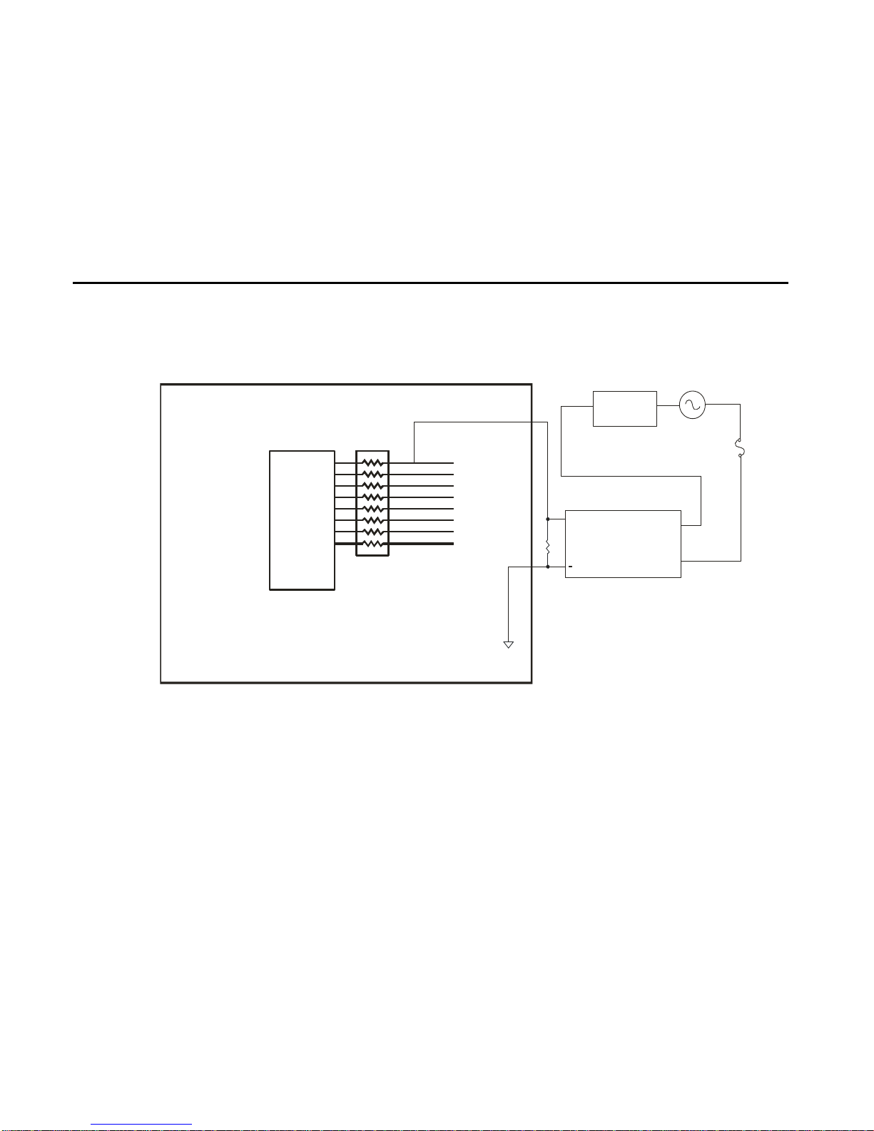
Typical Input Line Circuit – Internal Power
In p ut 8
In p ut 7
In p ut 6
In p ut 5
In p ut 4
In p ut 3
In p ut 2
In p ut 1
Signal G enerator M odel 501 A
DB25 Pin8
DB25 Pin7
DB25 Pin6
DB25 Pin5
DB25 Pin18
DB25 Pin17
DB25 Pin16
DB25 Pin15
O
P
T
G
N
D
OPT GND
NC-NO
U42
OPT_VCC
RP41
GPI0
GPI1
GPI2
GPI3
820
PS2501L-4
IN0
IN1
IN2
IN3
GPI4
GPI5
GPI6
GPI7
PS2501L-4
U41
VCC
IN4
IN5
IN6
2.7K
8
1236457
RP42
IN7
DB25 PIN22
DB25 PIN23
DB25 PIN24
DB25 PIN25
6
2143510879
TB40
OPT-GRD
TB-VCC
OPT-VCC
TB-GR D
+5V
1
2
3
JP84
VCC
JP85
GRD
1
2
3
2
1
9
10

FlashCut CNC Section 11 Appendix
47
Typical Input Line Circuit – External Power
In p u t 8
In p u t 7
In p u t 6
In p u t 5
In p u t 4
In p u t 3
In p u t 2
In p u t 1
Signal Generator M odel 501 A
DB25 P in8
DB25 P in7
DB25 P in6
DB25 P in5
DB25 P in18
DB25 P in17
DB25 P in16
DB25 P in15
O
P
T
G
N
D
OPT GND
NC-NO
U42
OPT_VCC
RP41
GPI0
GPI1
GPI2
GPI3
820
PS2501L-4
IN0
IN1
IN2
IN3
GPI4
GPI5
GPI6
GPI7
PS2501L-4
U41
VCC
IN4
IN5
IN6
2.7K
8
1236457
RP42
IN7
DB25 P IN22
DB25 P IN23
DB25 P IN24
DB25 P IN25
6
2143510879
TB40
OPT-GRD
TB-VCC
OPT-VCC
TB-GRD
+5V
1
2
3
JP84
VCC
JP85
GRD
1
2
3
2
1
9
10

FlashCut CNC Section 11 Appendix
48
The above schematic shows a typical connection of 5 normally closed switches. These switches are connected
between input lines 1-5 and ground. Lines 6-8 are connected directly to ground with jumper wires. All external
connections shown are made through the Input connector on the back of the Signal Generator. This resistor pack
(RP41) is socketed so that you can change the value if needed for your application.
The input lines are all optically isolated. In this example, JP84 and JP85 are shorted using the internal power
to source the external side of the optical couplers. However, for the best isolation, JP84 and JP85 should be
open, and power should be provided through pins 23 and 25 of the DB25 Motor Signal connector. Input lines
1-4 and 5- 8 are internally connected to pins 15-18 and 5-8 respectively of the DB25 Motor Signal connector.
Note that the FlashCut CNC limit switch kit has the same wiring as shown in this example.

FlashCut CNC Section 11 Appendix
49
Signal Generator Board Layout

FlashCut CNC Section 11 Appendix
50
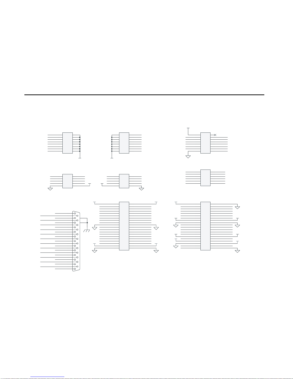
Connector Pin-Out Table
EXTERNAL CONNECTORS (RED)
CON1: STANDARD USB TYPE-A
CON3 – DB25F
GPO1
1
14
ENA
GP02
2
15
GPI1
STEP5
3
16
GPI2
DIR5
4
17
GPI3
GPI5
5
18
GPI4
GPI6
6
19
DIR4
GPI7
7
20
DIR3
GPI8
8
21
DIR2
DIR1
9
22
VCC
STEP4
10
23
OPT-VCC
STEP3
11
24
GND
STEP2
12
25
OPT-GND
STEP1
13 SHIELD
CON4 - INPUTS
OPT-GND
1 9 GPI1
OPT-GND
2
10
GPI2
OPT-GND
3
11
GPI3
OPT-GND
4
12
GPI4
OPT-GND
5
13
GPI5
OPT-GND
6
14
GPI6
OPT-GND
7
15
GPI7
OPT-GND
8
16
GPI8
CON5 - OUTPUTS
GPO1
1 6 GPO2
GPO3
2 7 GPO4
GPO5
3 8 GPO6
GPO7
4 9 GPO8
VCC
5
10
GND
INTERNAL CONNECTORS (ORANGE)
PIN 1 OF ALL HEADERS IS INDICATED
BY A SMALL WHITE DOT PRINTED ON
THE PCB.
JP30 – AUXILIARY INPUTS
2 X 20 - 2MM SPACING
+3.3V
1 2 +3.3V
GPI32
3 4 GPI1
GPI31
5 6 GPI2
GPI30
7 8 GPI3
GPI29
9
10
GPI4
GPI28
11
12
GPI5
GPI27
13
14
GPI6
GPI26
15
16
GPI7
GPI25
17
18
GPI8
GND
19
20
GND
GPI24
21
22
GPI9
GPI23
23
24
GPI10
GPI22
25
26
GPI11
GPI21
27
28
GPI12
GPI20
29
30
GPI13
GPI19
31
32
GPI14
GPI18
33
34
GPI15
GPI17
35
36
GPI16
+3.3V
37
38
+3.3V
GND
39
40
GND
JP31 – STATUS LEDS
2 X 8 - 2MM SPACING
+5V
1 2 N/C
LED-DIR1
3 4 LED-STEP1
LED-DIR2
5 6 LED-STEP2
LED-DIR3
7 8 LED-STEP3
LED-DIR4
9
10
LED-STEP4
LED-DIR5
11
12
LED-STEP5
LED-AUX
13
14
LED-USB
GND
15
16
LED-PWR
INTERNAL CONNECTORS (ORANGE)
JP32 – BUS EXPANSION
2 X 20 - 2MM SPACING
+3.3V
1 2 GND
CS6
3 4 STATUS6
TXD2
5 6 FAULT6
RXD2
7 8 AUX1-STB
OUT-ENA
9
10
AUX2-STB
OUT2-STB
11
12
OUT1-STB
OUT4-STB
13
14
OUT3-STB
+5V
15
16
+5V
GND
17
18
GND
A0
19
20
A1
DATA1
21
22
DATA2
DATA3
23
24
DATA4
DATA8
25
26
DATA7
DATA6
27
28
DATA5
+7V
29
30
+7V
SPHOME
31
32
ENC CLK
+3.3V
33
34
ENC DIR
AGND
35
36
AV+
DAC2
37
38
DAC1
ADC1
39
40
AGND
JP33 – STEP & DIRECTION
2 X 6 - 2MM SPACING
STEP5
1 2 ENA
STEP4
3 4 DIR5
STEP3
5 6 DIR4
STEP2
7 8 DIR3
STEP1
9
10
DIR2
GND
11
12
DIR1

FlashCut CNC Section 11 Appendix
51
INTERNAL CONNECTORS (ORANGE)
JP40 – INPUT AUX HEADER
2 X 8 - 2MM SPACING
GPI1
1 2 OPT-GND
GPI2
3 4 OPT-GND
GPI3
5 6 OPT-GND
GPI4
7 8 OPT-GND
GPI5
9
10
OPT-GND
GPI6
11
12
OPT-GND
GPI7
13
14
OPT-GND
GPI8
15
16
OPT-GND
JP50 – OUTPUT AUX HEADER
2 X 5 - 2MM SPACING
GPO2
1 2 GPO1
GPO4
3 4 GPO3
GPO6
5 6 GPO5
GPO8
7 8 GPO7
GND
9
10
VCC
JP53 – OUT 1&2 LOW SIDE DRIVER
1 X 6 - 2MM SPACING
+5V VCC
1
CLAMP for GP02
2
GPO2 Low Side Driver
3
GPO1 Low Side Driver
4
CLAMP for GP01
5
LOGIC GND
6
JP80 - REAR PANEL POWER
JP81 - REAR PANEL FUSE
JP82 - FRONT PANEL SWITCH
CONFIGURATION JUMPERS (BLUE)
PIN 1 OF ALL JUMPERS IS INDICATED BY
A SMALL WHITE DOT PRINTED ON THE
PCB.
JP83: DB TO USB GROUND
ALWAYS LEAVE PIN 1 JUMPED TO PIN
2, PIN3 JUMPED TO PIN 4 AND PIN 5
JUMPED TO PIN 6 UNLESS DIRECTED
OTHERWISE BY FLASHCUT TECH
SUPPORT.
JP84/JP85: INPUT POWER SELECT
SHOULD BE JUMPERED THE SAME
WAY…
1-2: INPUTS DRIVEN BY ON-BOARD
VCC
2-3: INPUTS BIASED BY VOLTAGE ON
TB40
JP86: USB GROUND
SHOULD BE JUMPED TO PULL USB
GROUND TO CHASSIS GROUND
JP87: CHASSIS GROUND
SHOULD BE JUMPED TO PULL
INTERNAL SIGNAL GROUND OF THE
SIGNAL GENERATOR TO CHASSIS
GROUND.
TERMINAL BLOCKS (GREEN)
TB40: ISOLATED INPUT POWER
VOLTAGE APPLIED HERE BIASES
INPUTS IF JP84/JP85 ARE SHORTED
PINS 2-3; DO NOT
EXCEED 5V ON THIS TERMINAL
UNLESS SPECIFICALLY ARRANGED
WITH FLASHCUT TECH SUPPORT.
TB80: SMC POWER (24V)
APPLY 24 VDC HERE TO BIAS THE
STEPPER MOTOR CONTROLLER
BOARD(S) PLUGGED INTO SLOTS
SMC1-SMC5

FlashCut CNC Section 11 Appendix
52
Power
+3.3V
3.3 V 3000 MA
1
2
TB80
MKDSN
LOGIC POWER
4.8 TO 15 V IN
HV-PWR
HV-GND
CHASSIS
HV-PWR
24-40 V AT UP TO 10 A FOR FUNCTION SLOTS
+5V
VCC
GND
POWER JUMPERS
UL CLASS C: 10 A @ 300 V WITH 14 AWG
1
2
JP87
10 A!
+5V
6.5 TO 25 V IN
5.0 V 3000 MA
9 - 24 VDC @ 2 A
LOW ESR LOW ESR
C85
0.1 UF
+
C82
22 UF
+
C83
22 UF
1
2
JP80
D80
TVS 26V 400W
1
2
JP81
FUSE
POWER
1
2
JP82
SWITCH
+7V
+3.3V
VIN3+5.0
2
+5.0
4
GND
1
U80
LM1085IS-5.0
FWB80
GBPC6005
1
2
TB40
MKDSN
TB-VCC
TB-GND
OPT-VCC
OPT-GND
NOTE 1.
FB80
434-6H-901
1
2
3
JP84
1
2
3
JP85
VIN3+3.3
2
+3.3
4
GND
1
U81
LM1085IS-3.3
NOTE 1.
UPPER RIGHT SCREW MOUNT HOLE IS CHASSIS
FOR U80
5734
FOR U81
5734
HEATSINK HEATSINK
+
C80
330 UF
C86
1 UF
+
C84
330 UF
C81
1 UF
1 2
3 4
5 6
JP83
Header 3X2
USBSHIELD
1
2
JP86
DBSHIELD USBSHIELD
SYSTEM GROUNDING OPTIONS
C87
0.001 UF
R87
1M
C88
0.1 UF

FlashCut CNC Section 11 Appendix
53
Outputs
GPO0
GPO1
GPO2
GPO3
GPO4
GPO5
GPO6
GPO7
LED-USB
LED-AUX
LED-PWR
OUT1-STB
OE
1
LE
48
D147Q1
2
D246Q2
3
D344Q3
5
D443Q4
6
D541Q5
8
D640Q6
9
D738Q7
11
D837Q8
12
U50A
74ACT16373DL
DATA0
DATA1
DATA2
DATA3
DATA4
DATA5
DATA6
DATA7
OE
24
LE
25
D136Q1
13
D235Q2
14
D333Q3
16
D432Q4
17
D530Q5
19
D629Q6
20
D727Q7
22
D826Q8
23
U50B
74ACT16373DL
VOH = 4.3 V
VOL = 0.44 V
AT 24 MA THRU 22 OHMS:
VOH = 3.8 V
VOL = 0.97 V
VBUS-OK
PANEL LED DRIVER
5V-OKVBUS OKAXIS1 AXIS2 AXIS3 AXIS4
12
CR51
GRN
12
CR52
GRN
12
CR53
GRN
12
CR54
GRN
12
CR57
YEL
1
2
3
4
5
6
7
8
16
15
14
13
12
11
10
9
RP51
22 OHM
1
2
3
4
5
6
7
8
16
15
14
13
12
11
10
9
RP54
470
+5V
AXIS5
12
CR55
GRN
CR61
ORG
FOR DEBUG
OUT-ENA
LED-ST1
LED-ST2
LED-ST3
LED-ST5
LED-ST4
SEE MAKO-IF SHEET FOR DIR LED DRIVE U52B
ENCODER DIR
LED-STEP1
LED-STEP2
LED-STEP3
LED-STEP4
LED-STEP5
R57
10K
+5V
+5V
12
CR58
GRN
STEP LEDS
S
1
2Y
6
1A
2
2A
7
VCC
8
GND
4
1Y
3
CLM
5
U53
SN75477D
+5V
1
2
3
4
5
6
JP53
RELAY DRIVE
24V 300MA
5-24V RAIL
LO-SIDE OUT0
LO-SIDE OUT1

FlashCut CNC Section 11 Appendix
54
Inputs
GPI 0
GPI 1
GPI 2
GPI 3
GPI 4
GPI 5
GPI 6
GPI 7
PS 2501L-4
U 42
PS 2501L-4
U 41
O P T-V C C
+3 .3 V
1
2
3
4
5
6
7
8
9
10
820
R P4 1
SOCKETED
1
2
3
4
5
6
7
8
16
15
14
13
12
11
10
9
2.7K
R P4 2
IN 0
IN 1
IN 2
IN 3
IN 4
IN 5
IN 6
IN 7
FlashCut CNC Section 11 Appendix
55
Connectors
1
2
3
4
5
6
7
8
9
10
WM 3904
CO N5
GP O0 GPO 1
GP O2 GPO 3
GP O4 GPO 5
GP O6 GPO 7+5 V
1
2
3
4
5
6
7
8
9
10
11
12
13
14
15
16
WM 3907
CO N4
GPI 0
GPI 1
GPI 2
GPI 3
GPI 4
GPI 5
GPI 6
GPI 7
O P T-G N D
BAC K PANEL MINI- FI T JR.S
EN A
1
20
2
21
3
22
4
23
5
24
6
25
7
8
9
10
11
12
13
14
15
16
17
18
19
27
26
DB -25M
CO N3
+5V
OPT-V CC
GN D
OPT-G ND
SE E M AKO -IF. SC HDO C FOR
MA KO H EAD ERS 2 X10 (5 EA )
SE E M CU .SCH DO C FOR
SEE PO WE R.SC HDO C F OR
HV & 5 V TE RMIN AL BLO CK S
PWR & SH IELD ING JU MPER S
SEE US B.SCH DO C FO R
US B CO NN ECTO R 1X4
GPO 0
GPO 1
ST 5
DR 5
GPI 0
GPI 1
GPI 2
GPI 3
GPI 4
GPI 5
GPI 6
GPI 7
AN D PAC U
ST1
ST2
ST3
ST4
DR 1
DR 2
DR 3
DR 4
1 2
3 4
5 6
7 8
9 10
HD R5X 2
JP50
OU TPU T A UX HEAD ER
1 2
3 4
5 6
7 8
9 10
11 12
13 14
15 16
HD R8X 2
JP40
IN PU T A UX HEAD ER
O P T-G N D
+5 V
PINO UTS AR E FOR 1:1 MAP PING TO M INI-FIT JR. FO R JTAG HEAD ER 2 X5
GPO 0GPO 1
GPO 2GPO 3
GPO 4GPO 5
GPO 6GPO 7
EXP ANS ION
GPI 0
GPI 1
GPI 2
GPI 3
GPI 4
GPI 5
GPI 6
GPI 7
1 2
3 4
5 6
7 8
9 10
11 12
13 14
15 16
17 18
19 20
21 22
23 24
25 26
27 28
29 30
31 32
33 34
35 36
37 38
39 40
He ad er 2 0X2
JP30
ST ATU S6
FAUL T6
IN 8
IN 9
IN 11
IN 12
IN 13
IN 14
IN 15IN 16
IN 17
IN 18
IN 19
IN 20
IN 21
IN 22
IN 23<<
<
<
<
<
<
<
<>
>
>
>
>
>
>
>
>
+3 .3 V
1 2
3 4
5 6
7 8
9 10
11 12
13 14
15 16
HD R8X 2
JP31
ST AT US LED S (G EMV ISION )
LED- DR4
LED- DR5
LED -USBLED- AUX
LED -PW R
LED -ST 1
LED -ST 2
LED -ST 3
LED -ST 5
LED- DR1
LED- DR2
LED- DR3
LED -ST 4
+5 V
IN 24
IN 25
IN 26
IN 27
IN 28
IN 29
IN 30
IN 31
ENC OD ER DIR
MC U-D AC0MC U-D AC1
MC U-A DC0
OU T4 -STB
AU X1- STB
AU X2- STB
AN D PACU
DATA 0 DATA 1
DATA 2 DATA 3
DATA 4DATA 5
DATA 6DATA 7
OU T3-S TB
OU T2 -STB
+5 V
EX PAN SION
<
<
<
<>
>
>
>
>
+3 .3 V
ENC OD ER CL KSP HO ME
AGND
OU T1-S TB
OU T-ENA
+5 V
>
+3 .3 V
>
>
>
>
>
>
>
>
<
<
<
<
<
<
<
+3 .3 V
+3 . 3 V
+3 . 3 V
AG ND
AV+
<
1 2
3 4
5 6
7 8
9 10
11 12
13 14
15 16
17 18
19 20
21 22
23 24
25 26
27 28
29 30
31 32
33 34
35 36
37 38
39 40
He ader 20X2
JP32
+3 .3 V
Rx D2
TxD 2
FR OM M CU
TO M CU
>
<
<
>
>CS 6
<
IN 0
IN 1
IN 2
IN 3
IN 4
IN 5
IN 6
IN 7
IN 10
1 2
3 4
5 6
7 8
9 10
11 12
WM 18561
JP33
ST EP & DIR ( GEMV ISIO N)
ENA
GN D
ST 5
DR 5
ST 1
ST 2
ST 3
ST 4
DR 1
DR 2
DR 3
DR 4
A0 A1><
+7 V +7 V

FlashCut CNC Section 11 Appendix
56
Axis Plug-In Interface
DIR1
DIR2
DIR3
ST 1
ST 2
ST 3
ST 4
DR 1
DR 2
DR 3
1
2
3
4
5
6
7
8
16
15
14
13
12
11
10
9
22 OH M
RP5 5
ST P1
ST P2
ST P3
ST P4
ST PX & D IRX FROM CPL D
HV-P WR HV-P WR
HV -GN DHV -GN D
EA RTH
DR 1
DR 2
DR 3
DR 4
EN A
CS1
CS2
CS3
CS4
SM 0
SM 1
HV -P W RMA KO-1
MA KO-2
MA KO-3
MA KO-4
STAT US 4
STAT US 3
STAT US 2
STAT US 1
+5 V
FR OM M CU
TO M CU
FAULT 4
FAULT 3
FAULT 2
FAULT 1
ST 1
ST 2
ST 3
ST 4
SCO M1
SCO M2
SCO M3
SCO M4
Rx D2
TxD 2
1 2
3 4
5 6
7 8
9 10
11 12
13 14
15 16
171918
20
SKT 10X2
JP71
1 2
3 4
5 6
7 8
9 10
11 12
13 14
15 16
171918
20
SKT 10X2
JP73
1 2
3 4
5 6
7 8
9 10
11 12
13 14
15 16
171918
20
SKT 10X2
JP72
1 2
3 4
5 6
7 8
9 10
11 12
13 14
15 16
171918
20
SKT 10X2
JP74
DR 5
CS5
MA KO-5
STAT US 5
FAULT 5
ST 5
SCO M5
1 2
3 4
5 6
7 8
9 10
11 12
13 14
15 16
171918
20
SKT 10X2
JP75
OE
1
LE
48
D147Q1
2
D246Q2
3
D344Q3
5
D443Q4
6
D541Q5
8
D640Q6
9
D738Q7
11
D837Q8
12
74AC T16 373DLU52A
SM 0
SM 1
CS1
CS2
CS3
CS4
SCO M1
SCO M2
SCO M3
SCO M4
CS5
SCO M5
ST P5 ST 5
SCOM-STB
ILCS -ST B
OE
1
LE
48
D147Q1
2
D246Q2
3
D344Q3
5
D443Q4
6
D541Q5
8
D640Q6
9
D738Q7
11
D837Q8
12
74AC T16 373DLU51A
DATA 0
DATA 1
DATA 2
DATA 3
DATA 4
DATA 5
DATA 6
DATA 7
OE
24
LE
25
D136Q1
13
D235Q2
14
D333Q3
16
D432Q4
17
D530Q5
19
D629Q6
20
D727Q7
22
D826Q8
23
74AC T16 373DLU51B
DATA 0
DATA 1
DATA 2
DATA 3
DATA 4
DATA 5
DATA 6
DATA 7
1
2
3
4
5
6
7
8
16
15
14
13
12
11
10
9
22 OH M
RP5 2
1
2
3
4
5
6
7
8
16
15
14
13
12
11
10
9
22 OH M
RP5 3
FALLIN G ED GE OF I L-CSX IS
LATC H F OR SM0:1 O N M AKO-X
+5 V
+5 V
+5 V
+5 V
ST P-E NA
DIR4
EN AB LE
DR 4
EN A
DIR5
DR 5
LED -DR 4
LED -DR 5
OE
24
LE
25
D136Q1
13
D235Q2
14
D333Q3
16
D432Q4
17
D530Q5
19
D629Q6
20
D727Q7
22
D826Q8
23
74AC T16 373DLU52B
DIR1
DIR2
DIR3
DIR4
DIR5
LED -DR 1
LED -DR 2
LED -DR 3
ST P-E NA
IN 8
IN 9
IN 11
IN 12
IN 13
IN 14
IN 15
IN 16
IN 17
<
<
<
<
<
<
<
<
<
<
CS6
22R5 1
22R5 2
22R5 3
IN 10
10K
R5 6
+5 V S W
+5 V S W
FlashCut CNC Section 12 Internal Connections
57
12. Internal Connections

FlashCut CNC Section 12 Internal Connections
58
Connection Schematic
8 Amp Microstepping Drive 8 Amp Microstepping Drive 8 Amp Microstepping Drive
JP83
JP33
JP50
JP40
JP71
JP72
JP73
JP74
JP75
JP85
JP84
JP30
JP31
JP32
JP80
JP81
JP82
JP23
TB40
TB80
Signal Generator
P203
P108
P204
P103
P201
P101
C101
LED's
Power Board
Switch
Voltage
Selector
1
1A
1B
1A
1
2
2
2A
2A
2B
GND
N
L
AC
Inlet
To Fan
1
2
3
4
6
5
1
2
3
4
6
5
1
2
3
4
6
5
Axis 1
Axis 2
Axis 3
Axis 1
Axis 2 Axis 3
JP53
Relay
Output

FlashCut CNC Section 12 Internal Connections
1
Revision History
Revision
Date
Description of Revision
A
2/26/10
Initial write up
B
5/3/10
1st Edit
C
5/7/10
1st Revision
D
8/17/10
2
nd
Revision
E
11/03/10
3rd Revision
 Loading...