

Page 1

RadioRouter
Installation Guide
®
Base Station
Issue Date: 08-04-2003
Version 0.5
Flarion Technologies, Inc.
Bedminster One
135 Route 202/206 South
Bedminster, NJ 07921
Tel (908) 947 7000
Fax (908) 947 2050
Web: [email protected]
Page 2

Intentionally blank page
RadioRouter®BaseStation Installation Guide — Draft
Version 0.5 - © 2003
Page 3

COPYRIGHT STATEMENT
Copyright© 2003 Flarion Technologies, Inc. All rights reserved. Flarion™, flash-OFDM™, RadioRouter®,
Vector-LDPC™ and FlashView™ are trademarks of Flarion Technologies, Inc. All other trademarks
contained herein are the property of their respective owners. Data subject to change without notice.
Printed in USA. FTDS-200 013003
NOTICE:
Regulatory Compliance Information
The Flarion RadioRouter complies with the following regulatory compliance requirements:
• Safety
-
UL 60950 — Underwriters Laboratories, Inc.
-
CAN/CSA -C22.2 No. 60950 — Canadian Standards Association
-
EN 60950 — European Norm
-
IEC 60950 — International Electrotechnical Commission
• EMC — Electromagnetic Compatibility
-
FCC Part 15 (CFR 47) Class A — Federal Communications Commission, Code of Federal
Regulations
-
ICES-003 Class A — Interference-Causing Equipment Standard
-
EN55022 Class A
-
CISPR22 Class A
• Telecom
-
FCC Part 24
• Industry/Environmental
-
GR-63-CORE NEBS Level 3 — Network Equipment Building System
-
GR-1089-CORE NEBS Level 3
-
ETSI EN 300 019-2-3 V2.1.2 — European Telecommunications Standards Institute
i
FCCClassAStatement
This equipment has been tested and found to comply with the limits for a Class A digital device,
pursuant to Part 15 of the FCC rules. These limits are designed to provide reasonable protection
against harmful interference when the equipment is operated in a commercial environment.
This equipment generates, uses, and can radiate radio freque
and used in accordance with the instruction manual, may cause harmful interference to radio
communications. Operation of this equipment in a residential area is likely to cause harmful
interference in which case the user will be required to correct the interference at his own
expense. (CFR reference 15.105)
RadioRouter®BaseStation Installation Guide — Draft
Version 0.5 - © 2003
ncy energy and, if not installed
i
Page 4

ii
Modifying the equipment with out Flarion’s authorization may result in the equipment no longer
complying with FCC requirements for Class A digital device. In that event, your right to use
the equipment may be limited by FCC regulations, and you may be required to correct any
interference to radio or television communications at your own expense. (CFR reference 15.21)
Canadian Class A Statement
This Class ‘A’ digital apparatus complies with Canadian ICES-003.
Cet appareil numerique de la classe ‘A’ est conforme á la norme NMB-003 de Canada.
ii
RadioRouter®BaseStation Installation Guide — Draft
Version 0.5 - © 2003
Page 5

HOWTOUSETHISMANUAL
This manual is intended for use by qualified engineering personnel only. The RadioRouter
Base Station Installation Guide covers all of the necessary information required to install the
RadioRouter Base Station. It contains the following sections:
•Overview
• Verifying the Site Preparation
• Installing the Cabinet
• Connecting the Power System
• Connecting the Core Network Cables
• Connecting the Antennas Cables
• Installing the Alarm Connections
• Powering Up the RadioRouter
• Powering Down the RadioRouter
• Verifying the Installation
A list of abbreviations used in this manual can be found at the beginning of the document in the
LIST OF ABBREVIATIONS section.
iii
There is c ertain critical information contained within this manual that MUST be adhered to.
Failure to observe this information can result in death or serious injury. Such information is
marked as follows:
WARNING:
WARNINGS ARE ALWAYS IN UPPER CASE. WARNINGS RELATE TO
POTENTIALLOSSOFLIFEORSERIOUSINJURY.YOUMUSTOBEY
ALL WARNINGS.
CAUTION:
Normal Cautions are in bold type. Ca utions relate to potential damage to
equipment. You must obey all cautions.
ESD CAUTION:
This is an ESD caution. This is signified by the electrostatic symbol
which appears to the left of the caution information.
RadioRouter®BaseStation Installation Guide — Draft
Version 0.5 - © 2003
iii
Page 6

iv
Note:
Notes are displayed in italic. Notes contain certain information that may be valuable to the reader.
iv
RadioRouter®BaseStation Installation Guide — Draft
Version 0.5 - © 2003
Page 7

TABLE OF C ONTE NTS
1. Overview.....................................................................................Page 1
2. Verifying the Site Preparation ............................................................Page 3
2.1. Site Preparation Checklist — Indoor BaseStation ...............................Page 3
2.2. Preparing the Floor ...................................................................Page 4
3. Installing the Cabinet ......................................................................Page 6
4. Connecting the Power System ......................................................... Page 11
4.1. Routing the Cables ................................................................. Page 11
4.2. Connecting to Power and Ground................................................ Page 16
5. Connecting the Core Network Cables................................................. Page 21
6. Connecting the Antennas Cables...................................................... Page 26
7. Installing the Alarm Connections ...................................................... Page 30
8. Powering Up the Cabinet................................................................ Page 32
9. Powering Down the Cabinet ........................................................... Page 36
10. Verifying the Installation ............................................................... Page 37
10.1. Verifying the Physical Installation. .............................................. Page 37
10.2. Verifying the Base Station Operation .......................................... Page 37
v
LIST OF PROCEDURES
Procedure 3-1 Removing the Cabinet from the Pallet ...................................Page 6
Procedure 3-2 Lifting the Cabinet ...........................................................Page 9
Procedure 3-3 Mounting the Cabi net to the Floor ...................................... Page 10
Procedure 4-1 Routing Cables Through the Cable Entry Port........................ Page 12
Procedure 4-2 Connecting the Power Cables........................................... Page 18
Procedure 4-3 Connecting the Ground Cables . . ....................................... Page 19
Procedure 5-1 Connecting to the Network via T1 ...................................... Page 21
Procedure 5-2 Connecting to the Network via Ethernet ............................... Page 24
Procedure 6-1 Connecting the Antenna Cables . ....................................... Page 29
Procedure 8-1 Powering Up the Cabinet................................................. Page 33
Procedure 9-1 Powering Down the Cabinet ............................................. Page 36
Procedure 10-1 Communicating with the Core Network .............................. Page 37
LIST OF TABLES
Table 8.1 Power On Expected LEDs...................................................... Page 35
RadioRouter®BaseStation Installation Guide — Draft
Version 0.5 - © 2003
v
Page 8

vi
LIST OF FIGURES
Figure 1.1 Flat Equipment Dolly.............................................................Page 2
Figure 2.1 Clearance Holes in RadioRouter Base — Schematic View................Page 4
Figure 2.2 Clearance Holes in RadioRouter Base........................................Page 5
Figure 3.1 Side Brace and Screws..........................................................Page 7
Figure 3.2 Cabinet-to-Pallet Mounting Screws............................................Page 8
Figure 3.3 Top of Cabinet with Panels Removed .........................................Page 9
Figure 4.1 Cable Access Plate on Top of Cabinet ...................................... Page 11
Figure 4.2 Cable Entry Port ................................................................ Page 12
Figure 4.3 Channel Cover with Mounting Screw........................................ Page 13
Figure 4.4 Cable Routed in Cha nnel .. ................................................... Page 14
Figure 4.5 Cable Routed Through Structure ............................................ Page 15
Figure 4.6 Access to Power Connections — Front View . ............................. Page 16
Figure 4.7 Power Connections Viewed from inside the Cabinet ..................... Page 17
Figure 4.8 Schematic View of Power Connections ..................................... Page 17
Figure 4.9 Cabinet w ith Gro und Bus Bar — Rear View ............................... Page 19
Figure 4.10 Ground Bus Bar ............................................................... Page 20
Figure 5.1 Cabinet with T1 Connectors — Rear View . . . . ............................. Page 21
Figure 5.2 DSX Cables in T1 Connectors . . . ............................................ Page 22
Figure 5.3 DSX Cables Removed from T1 Connectors.. . ....................... ...... Page 23
Figure 5.4 Cabinet w ith Ethernet Connection — Front View.......................... Page 24
Figure 5.5 Route o f Ethernet Cable — Front View ..................................... Page 25
Figure 6.1 Top of Cabinet with Cable A ccess Plate Removed........................ Page 26
Figure 6.2 Antenna Connectors — Rear View .......................................... Page 28
Figure 6.3 Antenna Connectors S chematic — Rear View ............................ Page 28
Figure 6.4 Top of Cabinet with Two Antenna Cables Installed........................ Page 29
Figure 7.1 Cabinet with Alarm Connection — Rear View ............................. Page 31
Figure 7.2 Alarm Connector ............................................................... Page 31
Figure 8.1 Distribution Panel with Circuit Breakers — Front View ................... Page 33
Figure 8.2 Circuit B reakers — Front View ............................................... Page 34
Appendix A RadioRouter BaseStation Site Preparation Punchlist.................Page A -1
Appendix B RadioRouter BaseStation Installation Punchlist .......................Page B -1
vi
APPENDICES
RadioRouter®BaseStation Installation Guide — Draft
Version 0.5 - © 2003
Page 9

Page 7
LIST OF ABBREVIATIONS
DSX................................................................... Digital Signal Cross-Connect
LNA.............................................................................. Low Noise Amplifier
MCU ................................................................... .......... Master Control Unit
PA ............................................ ......................................... Power Amplifier
PCU.........................................................................Power Conditioning Unit
RRC........................................................................... Radio Router Chassis
RadioRouter®BaseStation Installation Guide — Draft
Version 0.5 - © 2003
Page 7
Page 10

Page 8
Intentionally blank page
Page 8
RadioRouter®BaseStation Installation Guide — Draft
Version 0.5 - © 2003
Page 11

Page 1
Chapter 1. Over view
The RadioRouter BaseStation Installation Guide covers all of the necessary information required
to physically install the RadioRouter BaseStation hardware. This guide assumes that a suitable
site has already been prepared. A checklist is provided to assess the site prior to installation.
Once the physical installation is complete, the RadioRouter BaseStation can be configured
and commissioned. Instructions for the configuration process can be found in the RadioRouter
BaseStation Commissioning Guide.
The RadioRouter BaseStation has the following physical characteristics:
• Standard EIA 19 inch rack mount
• 38 U of electronics mounting height
• 71”H X 24”W X 26.5”D with door and back panel installed
• 71”H X 24”W X 24.5”D without door and back panel installed
• 631 lb with door and back panel installed
• 559 lb without door and back panel installed
• Inherent forced air cooling
• Front access only required for maintenance
• Welded steel construction
• Antenna cable connectors on top 7/16” DIN female
• Power cable and T1 entry from top
• Color: Antique Ivory
WARNING:
THE RADIOROUTER BASESTATION INDOOR CABINET WEIGHS
APPROXIMATELY 650 LB AND IS TOP HEAVY. CARE MUST BE TAKEN
TO HANDLE THE CABINET PROPERLY WITHOUT DANGER TO THE
INSTALLATION PERSONNEL OR OTHER NEARBY EQUIPMENT.
IT IS THE RESPONSIBILITY OF THE INSTALLER TO ENSURE THAT
ALL LOCAL, STATE, AND FEDERAL SAFETY REQUIREMENTS ARE
FOLLOWED.
RadioRouter®BaseStation Installation Guide — Draft
Version 0.5 - © 2003
Page 1
Page 12
Page 2
ESD CAUTION:
It is the responsibility of the installer to ensu re that all necessary
precautions are taken to avoid electrostatic discharge damage to the
equipment.
Note:
All installation work must be coordinated with the carrier to insure compliance with carrier requirements regarding scheduling work during maintenance windows.
In addition to standard installation tools, it is recommended that special equipment be used to
move the RadioRouter cabinet. The following list gives examples of equipment which can be
used:
• Pallet jack with 27” width across the jacks. Pallet jack 4YX97 from Dayton or equivalent.
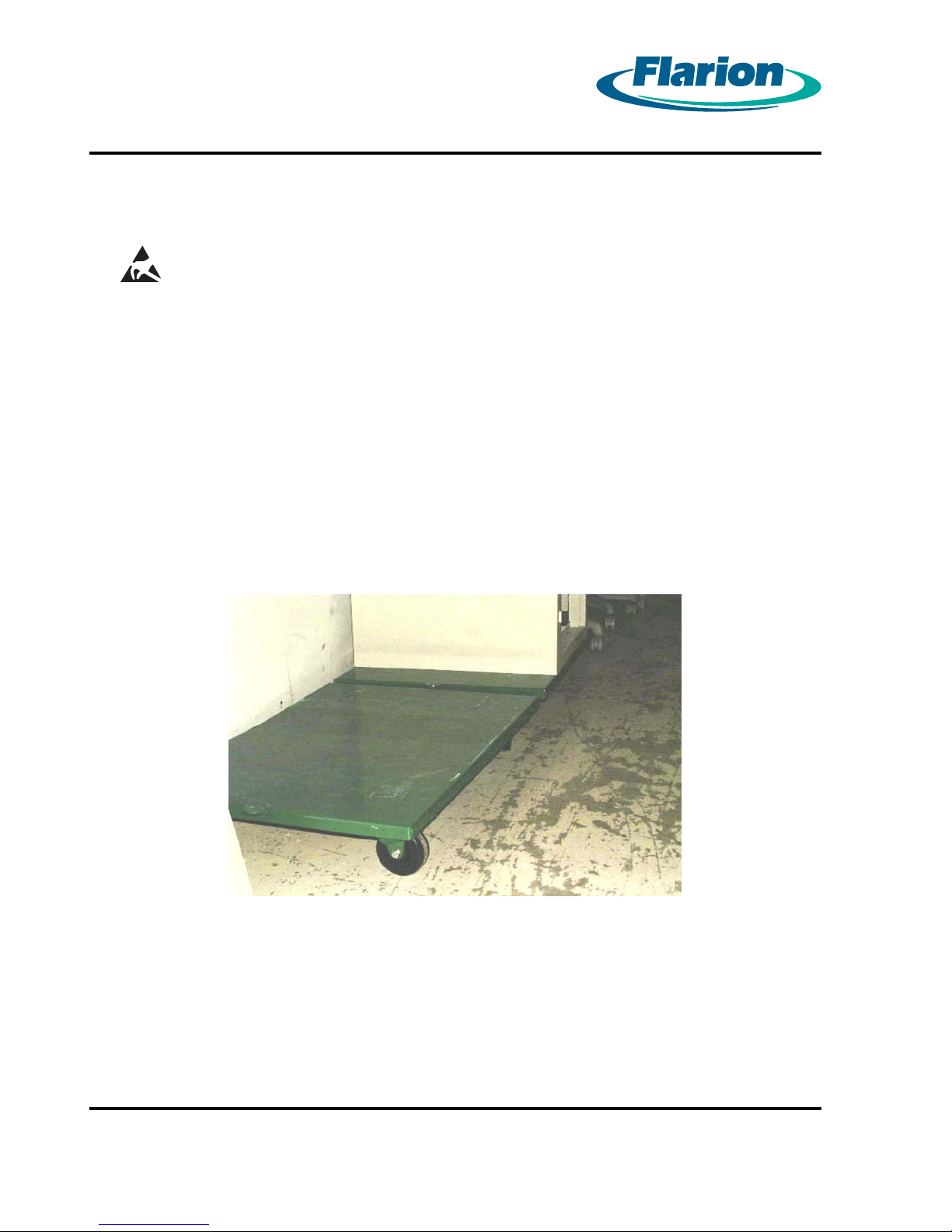
• A 36” L x 24” W x 5.5” H flat equipment dolly. McMaster Carr part number 2730T6 or equivalent.
See Figure 1.1 Flat Equipment Dolly
• Hoist or crane with heavy duty structural straps — 1000 lb load capability
Figure 1.1 Flat Equipment Dolly
Page 2
RadioRouter®BaseStation Installation Guide — Draft
Version 0.5 - © 2003
Page 13

Page 3
Chapter 2. Verifying the Site P reparation
Before you begin the physical installation of the RadioRouter BaseStation, confirm that the site
preparation is complete. The checklist that follows identifies all items that must be in place
before the installation can begin. If any items are incomplete or missing, fill out the Punchlist in
Appendix A - RadioRouter BaseStation Site Preparation Punchlist.
2.1. Site Preparation Checklist — Indoor BaseStation
• Floor Plan
-
Sketch of site indicating location of all equipment to be installed including base station cabinet and cables.
• Environment
-
Enclosed space with functional HVAC
-
Floor plan allows adequate space for cabinet — at least 24” front and 6” rear
• Electrical system
-
Load center, transfer switch, electrical outlets, and feeds for rectifiers available
-
Internal ground halo and master ground bar available
• Antenna plant
-
Surge arrestor mounting available
-
Six Tx/Rx antenna line surge protectors installed on surge arrestor mounting
• T1 connection
-
T1 surge arrestor installed
-
Surge arrestor grounded and ready to be connected to T1 network termination
• Alarm connection
-
One AC power failure alarm termination point — AMP 554954–2 connector
-
One high temperature alarm termination point — AMP 554954–2 connector
• Cable Support
-
Trays or other support mechanisms for cables available
• Cables
-
DC power cabling: #6 AWG THHN or THWN
-
Ground cabling to master ground bar: #6 AWG THHN or THWN
-
RF cabling to surge arrestors: Andrews 1/2” SuperFlex jumpers or equivalent
-
T1 cabling: 2–pair shielded
-
Alarm sensor cables
RadioRouter®BaseStation Installation Guide — Draft
Version 0.5 - © 2003
Page 3
Page 14
Page 4
2.2. Preparing the Floor
Before the cabinet can be placed into position, mounting holes must be drilled into the floor.
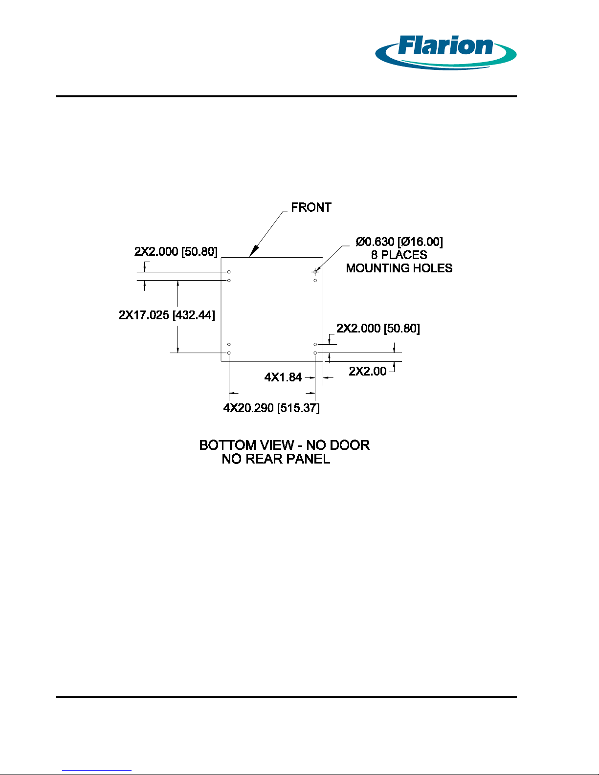
There are a total of 8 clearance holes in the base of the cabinet — 2 in each corner. Figure 2.1
Clearance Holes in RadioRouter Base — Schematic View shows the positioning of the holes.
Figure 2.1 Clearance Holes in RadioRoute r Base — Schematic View
Page 4
RadioRouter®BaseStation Installation Guide — Draft
Version 0.5 - © 2003
Page 15
Page 5
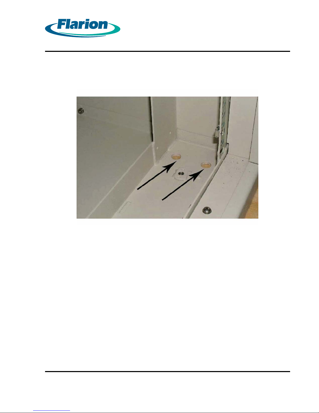
Figure 2.2 Clearance Holes in RadioRouter Base shows the holes as v iewed from inside the
front corner of the cabinet.
Figure 2.2 Clearance Holes in RadioRouter Base
Only one hole per cor ner is required to mount the cabinet. All holes must have threads to
accommodate 1/2” diameter bolts with flat washers, 1” minimum length.
RadioRouter®BaseStation Installation Guide — Draft
Version 0.5 - © 2003
Page 5
Page 16

Page 6
Chapter 3. Installing the Cabinet
The RadioRouter BaseStation cabinet is shipped completely assembled, shrouded in cardboard,
and mounted on a shipping pallet. The pallet is 35” L x 30” W x 6.75” H.
WARNING:
THE RADIOROUTER BASESTATIONINDOORCABINETWEIGHS
APPROXIMATELY 650 LB. AND IS TOP HEAVY. CARE MUST BE TAKEN
TO HANDLE THE CABINET PROPERLY WITHOUT DANGER TO THE
INSTALLAT ION PERSONNEL OR OTHER NEARBY EQUIPMENT.
Equipment that can be used to move the base station is described in Chapter 1. Overview.
Procedure 3-1 Removing the Cabinet from the Pallet
When this procedure is completed, the cabinet will be free to move directly into place.
Alternatively, the cabinet can be placed onto a flat dolly to facilitate moving the cabinet through
narrow equipment aisles. See Figure 1.1 Flat Equipment Dolly.
Remove the cardboard shroud and discard.
1.
Inspect the cabinet for damage. If there is any damage, fill out the Punchlist in Appendix
2.
B - RadioRouter BaseStation Installation Punchlist. If the damage is minor and does
not prevent continuation of the installation procedures, continue with the installation. If
the damage prevents continuation of the installation, contact the Project Manager for
instructions.
Page 6
RadioRouter®BaseStation Installation Guide — Draft
Version 0.5 - © 2003
Page 17
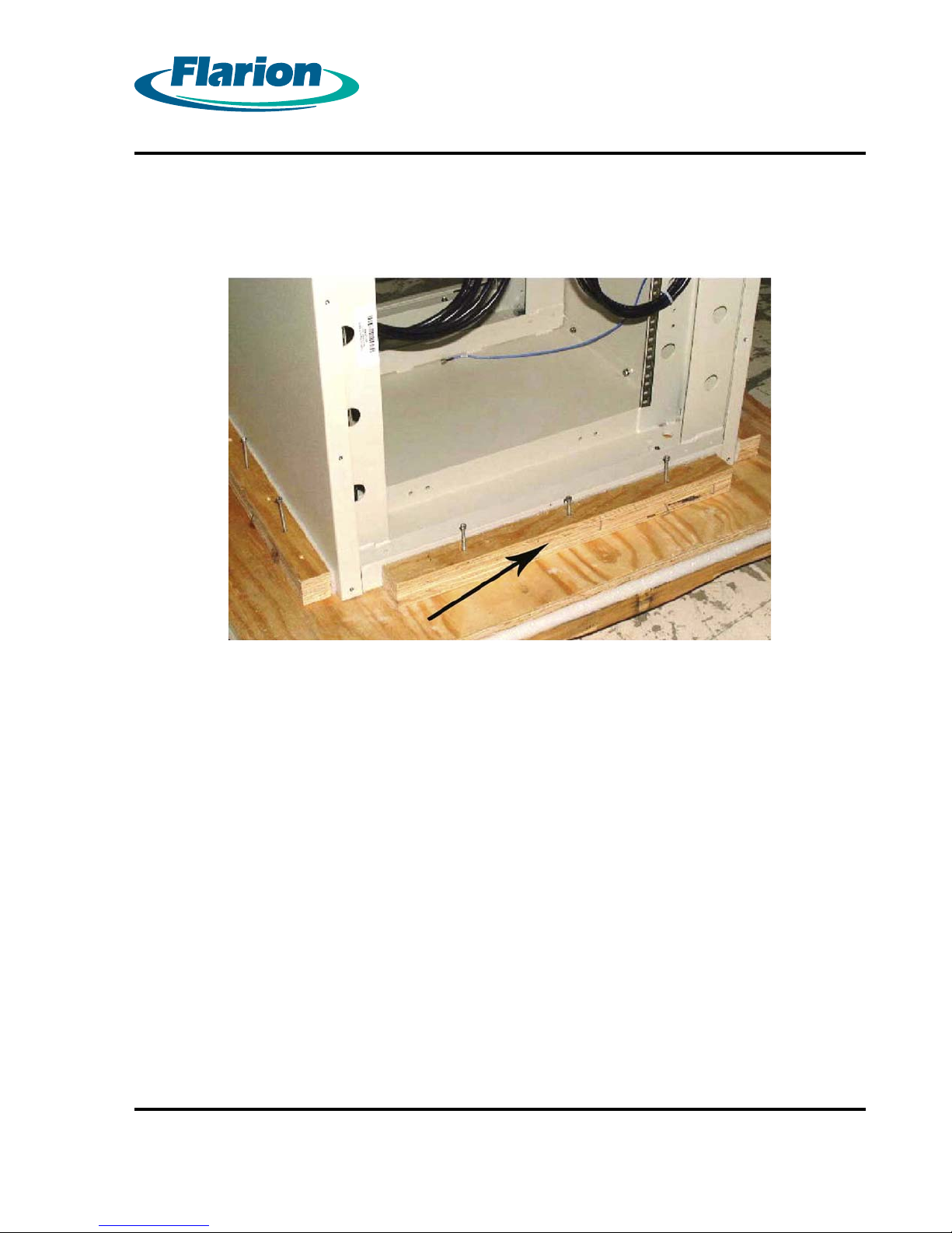
Locate the side support braces from the pallet. See Figure 3.1 Side Brace and Screws.
3.
Unscrew the braces and remove them.
Page 7
Figure 3.1 Side Brace and Screws
Open the front door of the cabinet. Lift the door upwards and remove the door from its
4.
hinges.
Unfasten all the screws on the rear panel and remove the panel.
5.
Note:
Reinstallation of the rear panel is optional. However, if the rear panel is to be reinstalled and there
is not sufficient rear clearance to reinstall the panel in place, the panel must be reinstalled prior to
final positioning of the cabinet.
Unscrew the 8 screws on the bottom front access panel. Remove the panel.
6.
RadioRouter®BaseStation Installation Guide — Draft
Version 0.5 - © 2003
Page 7
Page 18
Page 8
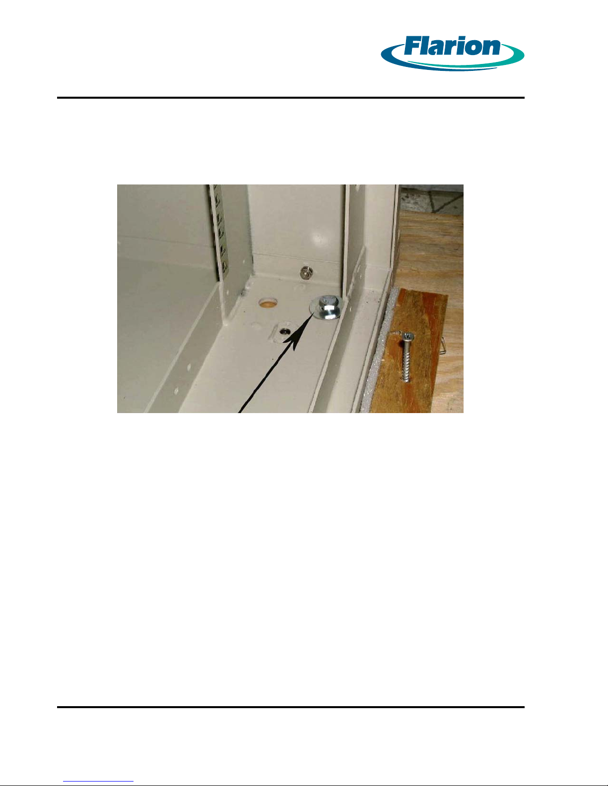
Unscrew the cabinet-to-pallet mounting screws. These are located on the inside corners of
7.
the cabinet. See Figure 3.2 Cabinet-to-Pallet Mounting Screws.
Page 8
Figure 3.2 Cabinet-to-Pallet Mounting Screws
RadioRouter®BaseStation Installation Guide — Draft
Version 0.5 - © 2003
Page 19

Page 9
Procedure 3-2 Lifting the Cabinet
Once the cabinet is near its final position, it can be moved into place. It is recommended that the
cabinet be lifted by a hoist or crane using heavy duty structural straps with 1000 lb load capability.
Note:
Before lifting the cabinet into place, make sure all necessary holes have been drilled. See Section
2.2. Preparing the Floor. Make sure the back panel and front door have been removed.
Remove the 1U blank panel at the top of the c abinet.
1.
Figure 3.3 Top of Cabinet with Panels Removed
Route the structural straps through the top of the cabinet from front to back.
2.
Lift the cabinet into place.
3.
Replace the 1U blank panel at the top of the cabinet.
4.
RadioRouter®BaseStation Installation Guide — Draft
Version 0.5 - © 2003
Page 9
Page 20

Page 10
Procedure 3-3 Mounting the Cabinet to the Floor
Once the cabinet has been moved to its final location, it must be bolted to the floor.
Note:
If the rear panel is to be reinstalled and there is not sufficient rear clearance to reinstall the panel
in place, the panel must be reinstalled prior to mounting the cabinet.
Align the clearance holes in the base of the cabinet to the threaded holes in the floor.
1.
Although there are two clearance holes in each corner, only one is necessary for mounting.
Screw the cabinet to the floor using 1/2” diameter screws and flat washers.
2.
Tighten the screws to 400 in-lb +/- 25 in-lb.
3.
Replace the front access panel after all cables have been routed and connected.
4.
Page 10
RadioRouter®BaseStation Installation Guide — Draft
Version 0.5 - © 2003
Page 21
Page 11
Chapter 4. Connecting the Power System
The RadioRouter BaseStation Indoor Cabinet requires a connection to DC power. This chapter
contains procedures for routing the power cables and connecting to power and ground.
WARNING:
WHEN PERFORMING ANY TASKS INVOLVING THE POWER SYSTEMS,
MAKE SURE THAT THE POWER IS NOT LIVE. ALL POWER OPERATIONS
SHOULD BE PERFORMED BY QUALIFIED PERSONNEL ONLY.
4.1. Routing the Cables
Cables are routed from the top of the cabinet either through the cable access opening or through
one of the cable entry ports.
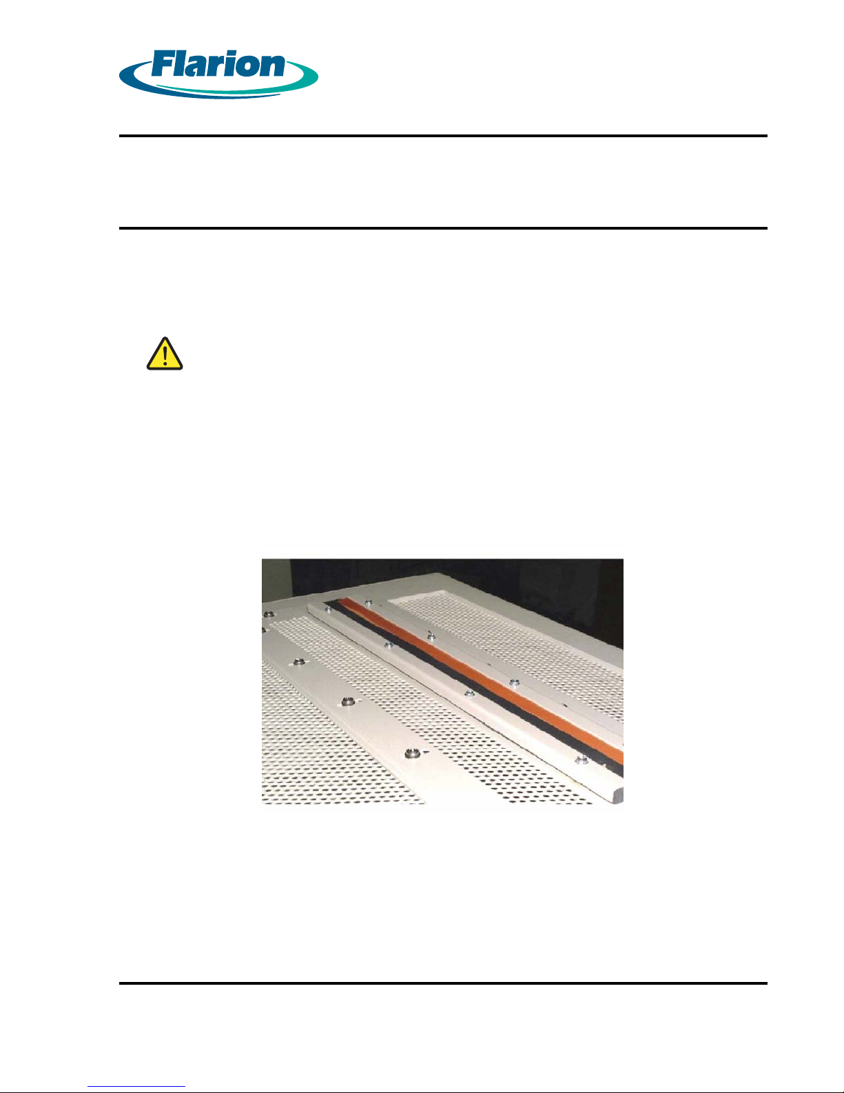
The cable access opening is located across the top of the cabinet as shown in Figure 4.1 Cable
Access Plate on Top of Cabinet.
Figure 4.1 Cable Access Plate on Top of Cabinet
RadioRouter®BaseStation Installation Guide — Draft
Version 0.5 - © 2003
Page 11
Page 22
Page 12
Procedure 4-1 Routing Cables Through the Cable Entry Port
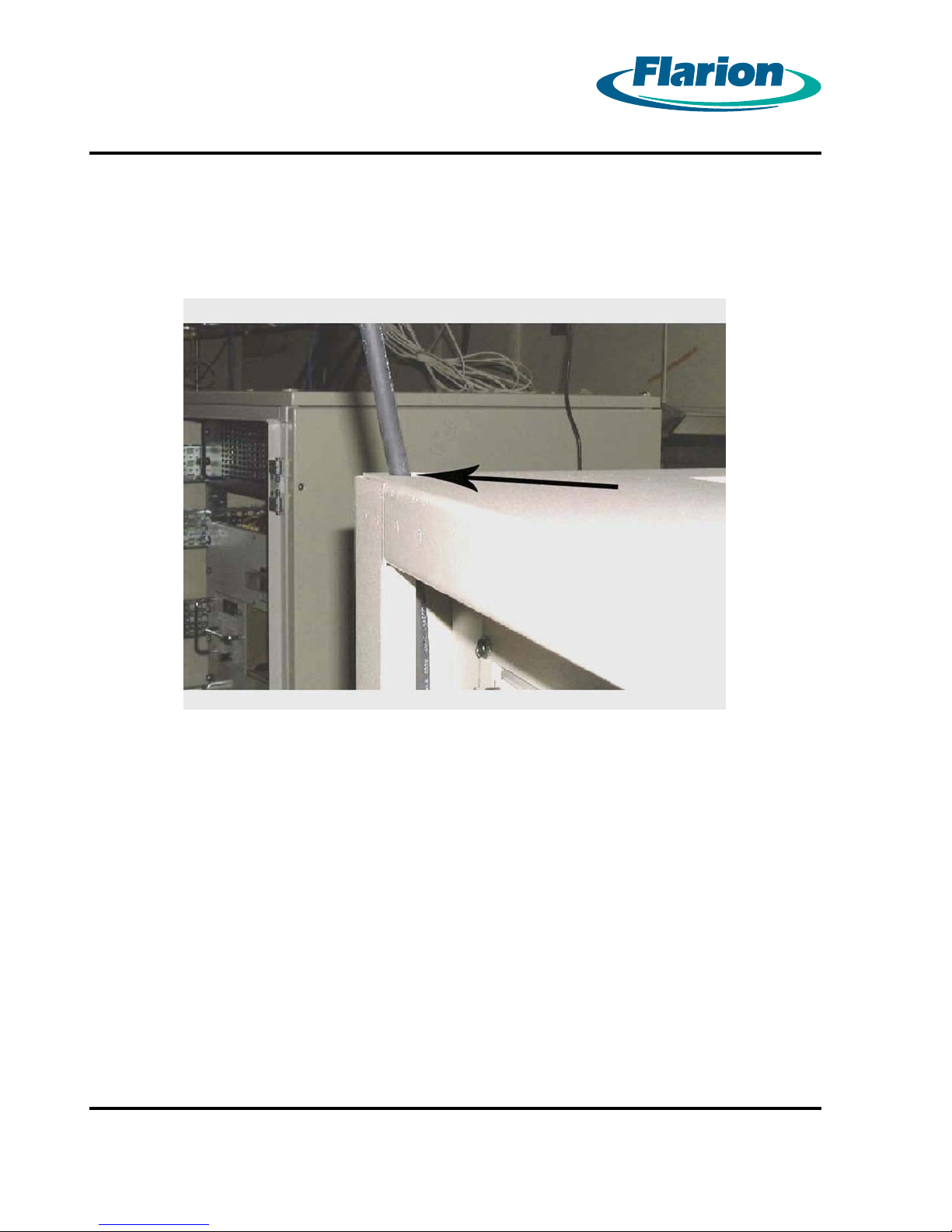
There are two cable entry ports located in the top front corners as shown in Figure 4.2 Cable
Entry Port.
Page 12
Figure 4.2 Cable Entry Port
RadioRouter®BaseStation Installation Guide — Draft
Version 0.5 - © 2003
Page 23
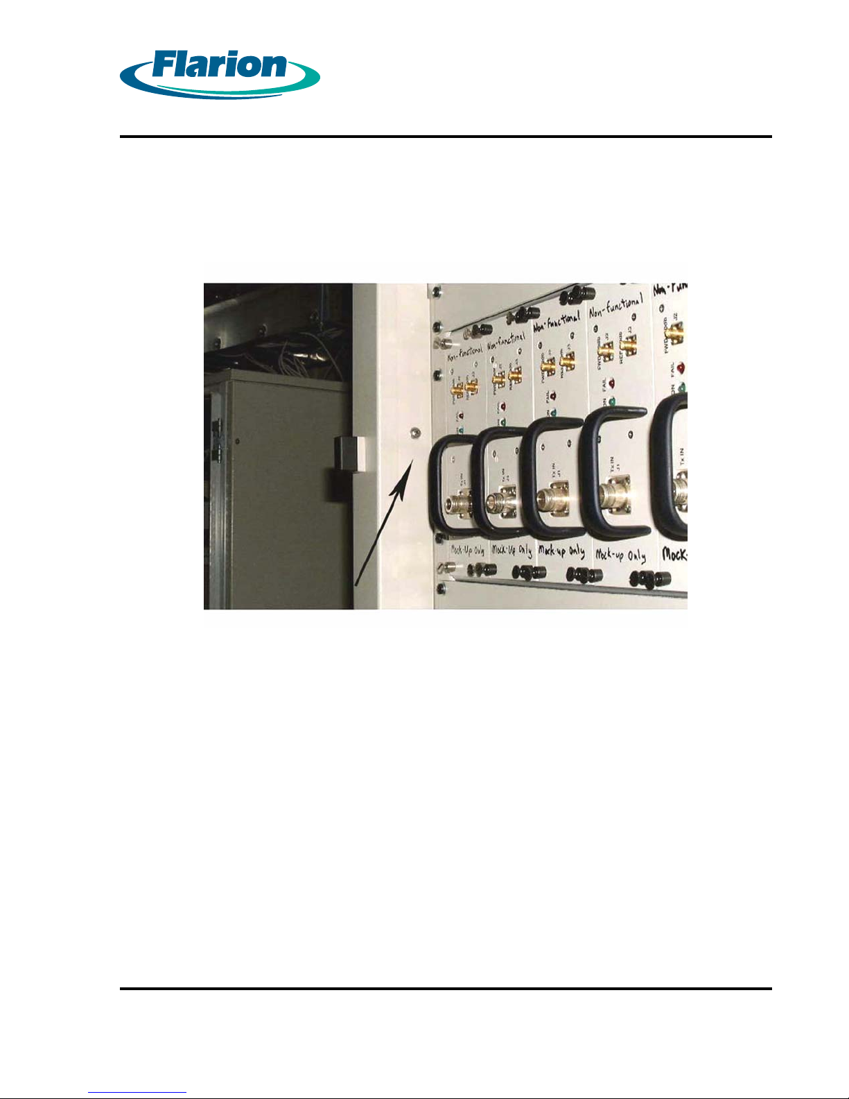
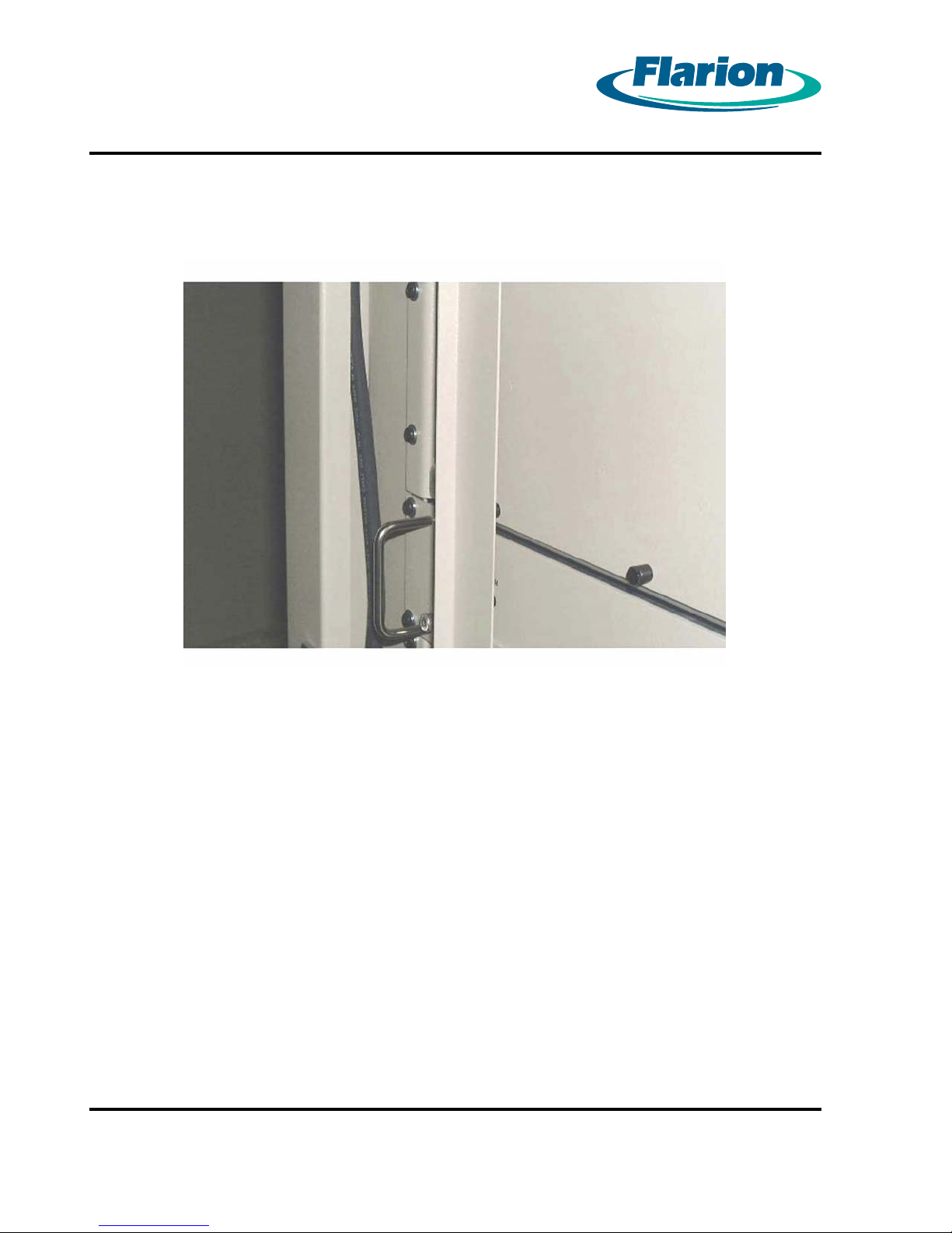
To route a cable through a cable entry hole, the cable channel covers must be removed.
1.
Figure 4.3 Channel Cover with Mounting Screw shows the cable channel cover in place.
Remove all three mounting screws and remove the channel cover.
Page 13
Figure 4.3 Channel Cover with Mounting Screw
RadioRouter®BaseStation Installation Guide — Draft
Version 0.5 - © 2003
Page 13
Page 24
Page 14
Route the cable through the channel to the lower portion of the cabinet.
2.
Page 14
Figure 4.4 Cable Routed in Channel
RadioRouter®BaseStation Installation Guide — Draft
Version 0.5 - © 2003
Page 25
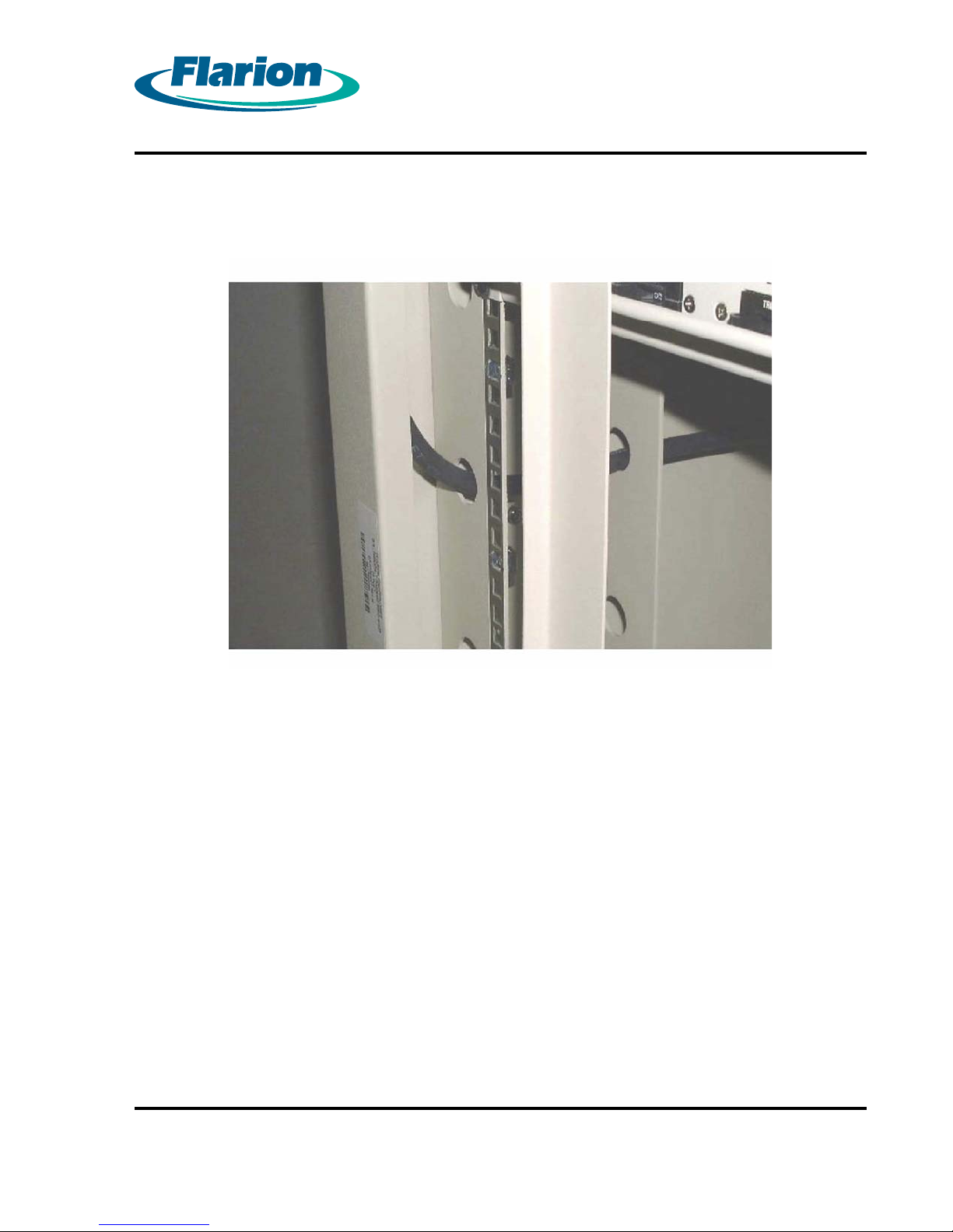
Route the cable through the holes in the cabinet structure to access the connection point.
3.
Page 15
Figure 4.5 Cable Routed Through Structure
When all cables have been routed, reinstall the channel covers.
4.
RadioRouter®BaseStation Installation Guide — Draft
Version 0.5 - © 2003
Page 15
Page 26
Page 16
4.2. Connecting to Power and Ground
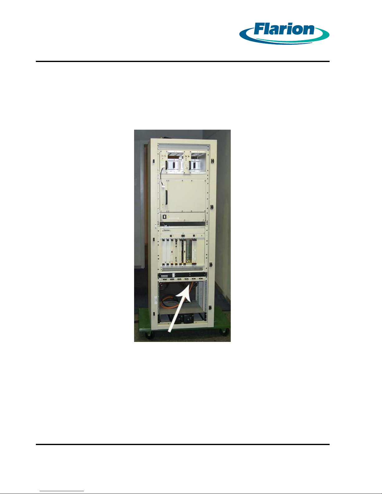
The power distribution panel with the power connections are located at the bottom of the
cabinet. The power distribution panel contains circuit breakers and is visible from the front. The
connections are at the bottom of the panel. To reach them, remove the front access panel.
Figure 4.6 Access to Power Connections — Front View
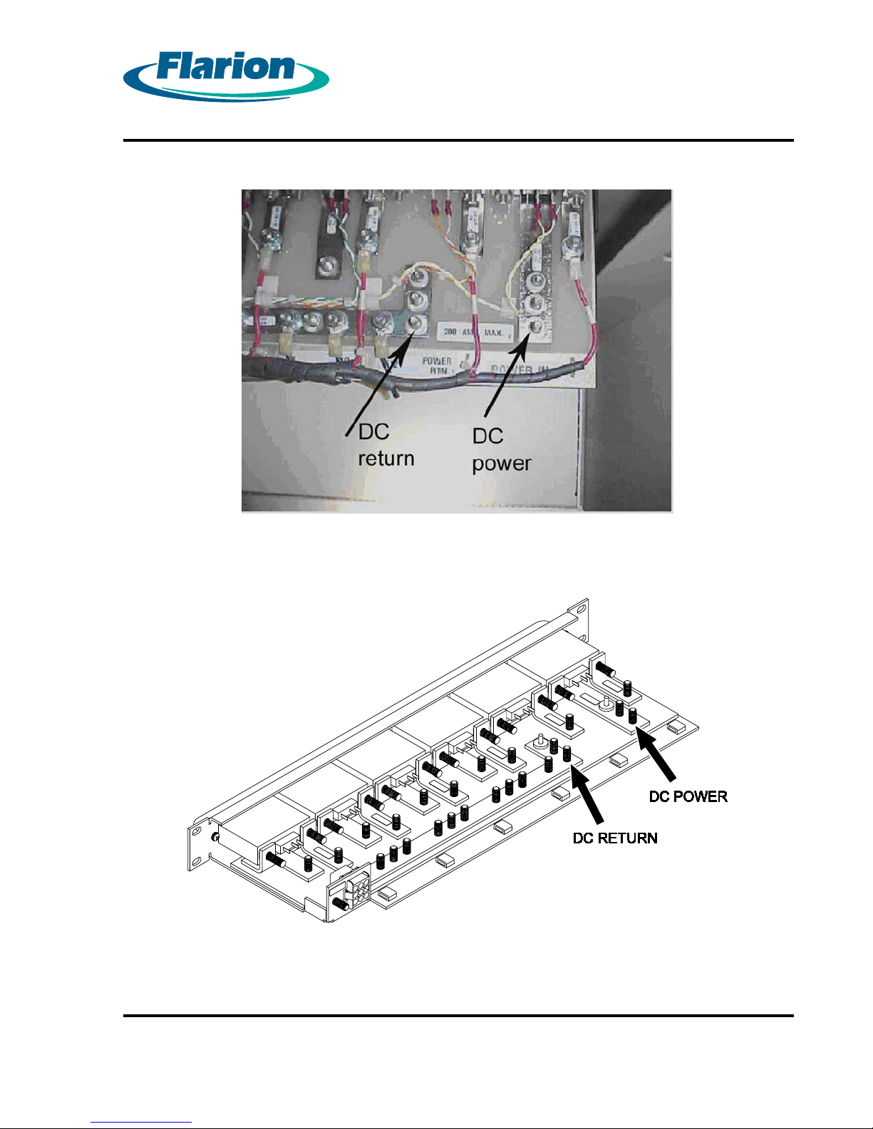
Once the front panel is removed, the connections are visible from underneath.
Page 16
RadioRouter®BaseStation Installation Guide — Draft
Version 0.5 - © 2003
Page 27
Page 17
Figure 4.7 Power Connections Viewed from inside the Cabinet
Figure 4.8 Schematic View of Power Connections
RadioRouter®BaseStation Installation Guide — Draft
Version 0.5 - © 2003
Page 17
Page 28
Page 18
Procedure 4-2 Connecting the Power Cables
WARNING:
WHEN PERFORMING ANY TASK S INVOLVING THE POWER SYSTEMS,
MAKE SURE THAT THE POWER IS NOT LIVE. ALL POWER OPERATIONS
SHOULD BE PERFORMED BY QUALIFIED PERSONNEL ONLY.
Locate the DC power connection point and the DC return connection point. See Figure
1.
4.7 Power Connections Viewed from inside the Cabinet and Figure 4.8 Schematic View of
Power Connections.
Connect the power cable to the connectors with 6 AWG wire with a 2–hole lug for a 1/4”
2.
diameter stud.
Fasten the lug on to the stud with the nuts provided. Tighten nuts to 40–50 in-lb torque.
3.
Connect the other end of the cable to the DC power source.
4.
Page 18
RadioRouter®BaseStation Installation Guide — Draft
Version 0.5 - © 2003
Page 29
Procedure 4-3 Connecting the Ground Cables
The cabinet must be connected to earth ground at the installation site.
CAUTION:
Failure to properly connect the cabinet to ground could result in
permanent damage to the equipment.
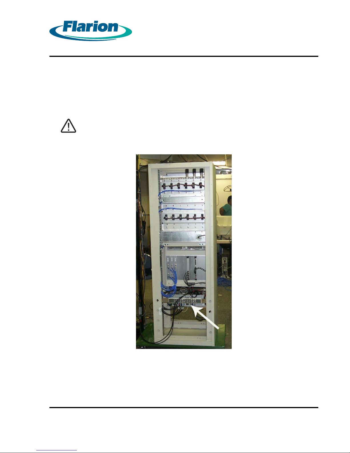
Locate the ground bus bar. See Figure 4.9 Cabinet with Ground Bus Bar — Rear View.
1.
Page 19
Figure 4.9 Cabinet with Ground Bus Bar — Rear View
RadioRouter®BaseStation Installation Guide — Draft
Version 0.5 - © 2003
Page 19
Page 30
Page 20
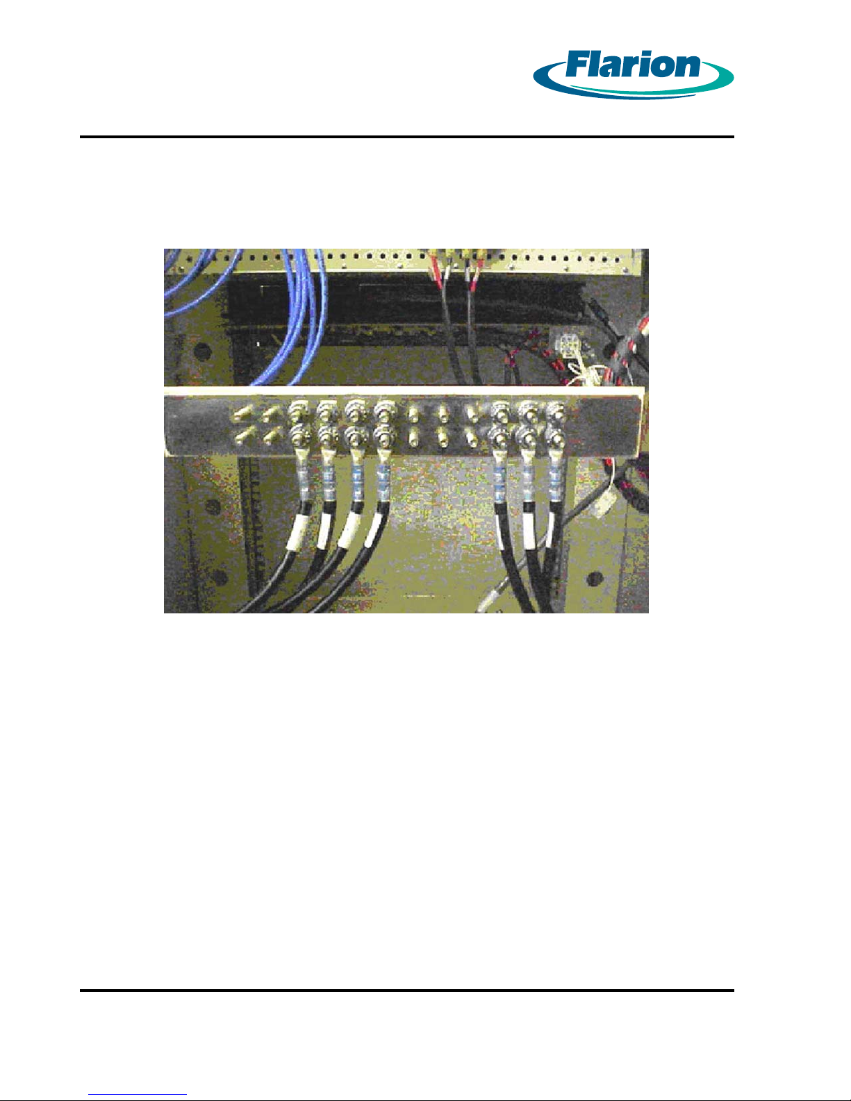
Connect the ground cable to the connectors with 6 AWG wire with a 2–hole lug for a 1/4”
2.
diameter stud. SeeFigure 4.10 Ground Bus Bar.
Figure 4.10 Ground Bus Bar
Fasten the lug on to the stud with the nuts provided. Tighten nuts to 40–50 in-lb torque.
3.
Connect the other end of the cable to the Master Ground Bar or other suitable ground
4.
source available at the installation site.
RadioRouter®BaseStation Installation Guide — Draft
Version 0.5 - © 2003
Page 20
Page 31
Page 21
Chapter 5. Connecting the Core Network Cables
The RadioRouter BaseStation can access the core network through either T1 or Ethernet
connections. This section describes both methods.
Procedure 5-1 Connecting to the Network via T1
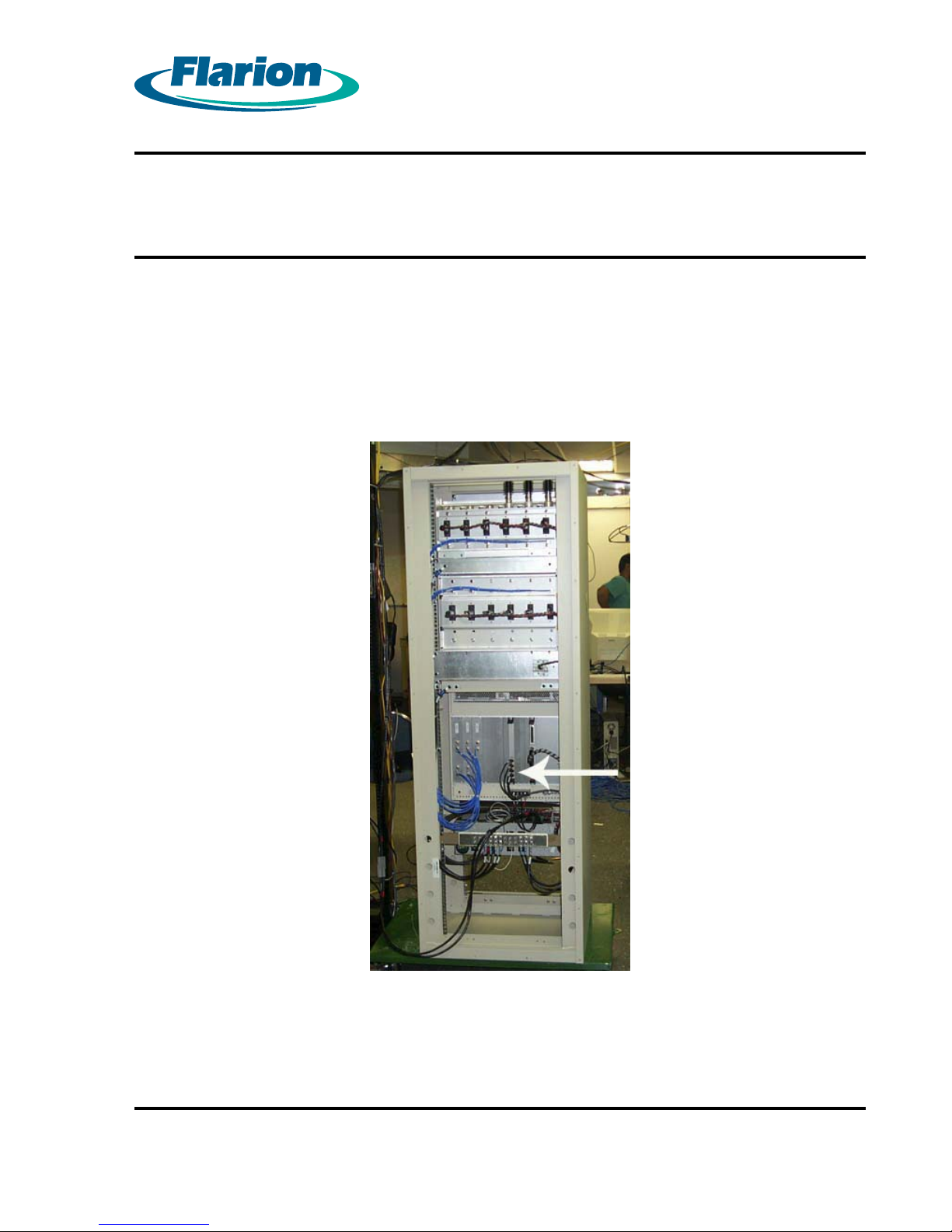
T1 connections are made using cables terminated in RJ-48 connectors.
Locate the T1 connectors on the rear of the cabinet.
1.
Figure 5.1 Cabinet with T1 Connectors — Rear View
RadioRouter®BaseStation Installation Guide — Draft
Version 0.5 - © 2003
Page 21
Page 32
Page 22
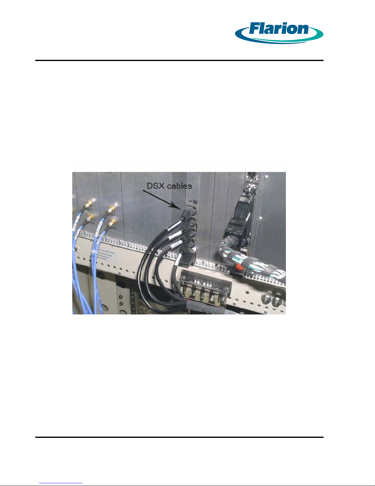
Remove the DSX cables from the connectors. Figure 5.2 DSX Cables in T1 Connectors
2.
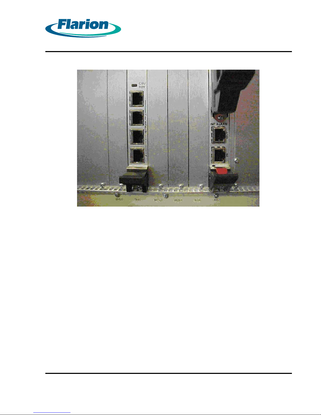
shows the cables in the connectors. Figure 5.3 DSX Cables Removed from T1 Connectors
shows the connectors with the cables removed.
Note:
Removing the D SX cables will disable the DSX-1 panel. The DSX cables must be reconnected to
use the DSX-1 panel.
Figure 5.2 DSX Cables in T1 Connectors
Page 22
RadioRouter®BaseStation Installation Guide — Draft
Version 0.5 - © 2003
Page 33
Page 23
Figure 5.3 DSX Cables Removed from T1 Connectors
Insert the first RJ-48 plug into the top jack which is labeled 1.
3.
Insert any additional plugs from the top down.
4.
RadioRouter®BaseStation Installation Guide — Draft
Version 0.5 - © 2003
Page 23
Page 34
Page 24
Procedure 5-2 Connecting to the Network via Ethernet
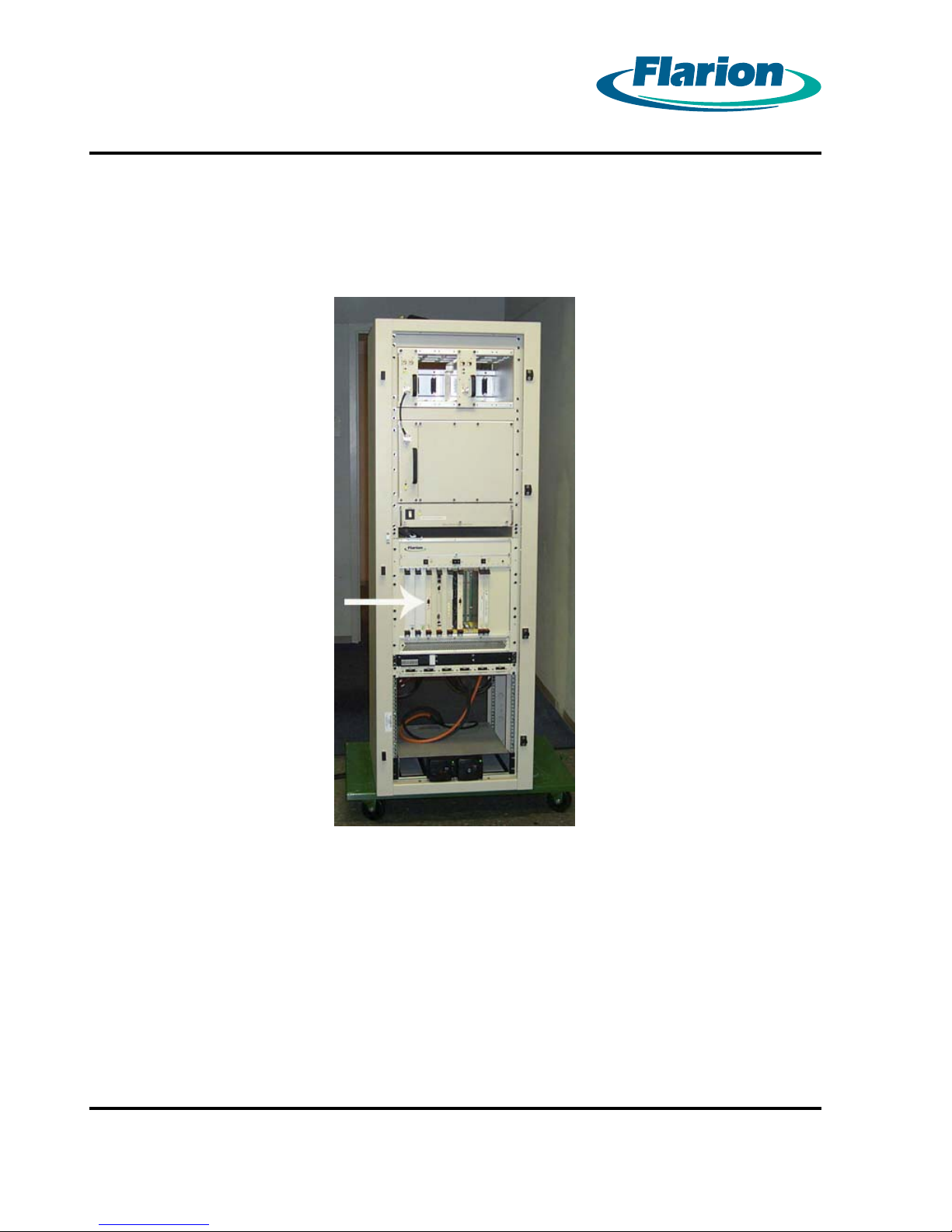
Ethernet connections are made using RJ-45 connectors. Figure 5.4 Cabinet with Ethernet
Connection — Front View shows the location of the Ethernet connector on the front of the cabinet.
Figure 5.4 Cabinet with Ethernet Connection — Front View
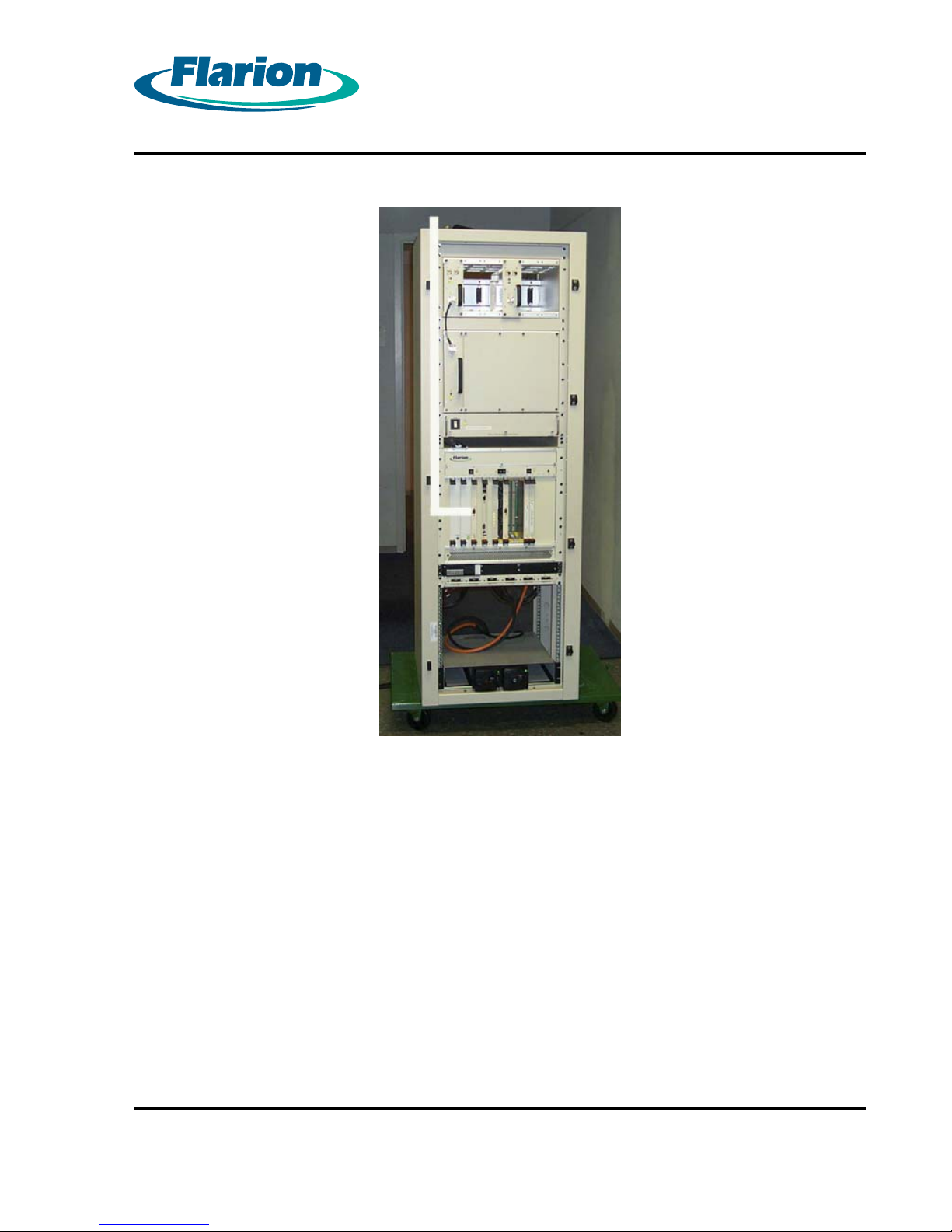
Route the Ethernet cable to the side cable channel and up the channel through the cable entry
port in the top of the cabinet as shown in Figure 5.5 Route of Ethernet Cable — Front View.
Page 24
RadioRouter®BaseStation Installation Guide — Draft
Version 0.5 - © 2003
Page 35
Page 25
Figure 5.5 Route of Ethernet Cable — Front View
RadioRouter®BaseStation Installation Guide — Draft
Version 0.5 - © 2003
Page 25
Page 36
Page 26
Chapter 6. Connecting the Antennas Cables
The antenna cables are connected through the cable access plate on the top of the cabinet.
Figure 4.1 Cable Access Plate on Top of Cabinet shows the cable access plate in place.
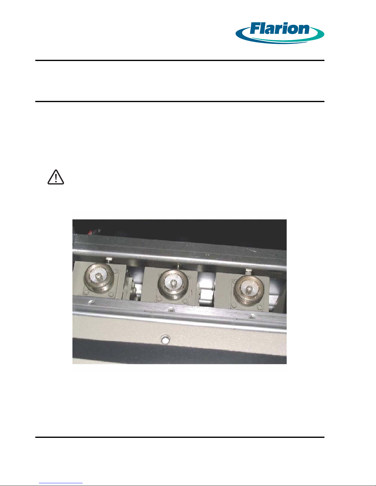
Before connecting the cables, the cable access plate must be removed. This gives access to the
cable mating connectors. See Figure 6.1 Top of Cabinet with Cable Access Plate Removed.
CAUTION:
All antenna ope rations should be performed by qualified personnel only.
Installers must meet the requirements of FCC Bulletin OET 65 and coax
terminations and have expertise working with RF coaxial cable. Care
must be taken not to crimp or d amag e the cables.
Figure 6.1 Top of Cabinet with Cable Access Plate Re moved
Page 26
RadioRouter®BaseStation Installation Guide — Draft
Version 0.5 - © 2003
Page 37

Page 27
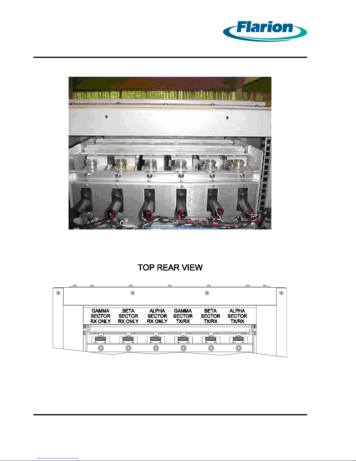
There are six Din Female connectors. From right to left they are:
1. Alpha sector Tx/Rx
2. Beta sector Tx/Rx
3. Gamma sector Tx/Rx
4. Alpha sector RX only
5. Beta sector Rx only
6. Gamma sector Rx only
The antenna cables that attach to the connectors should be clearly labeled with color-coded
bands as follows:
1. Alpha sector Tx/Rx — 1 white band
2. Beta sector Tx/Rx — 1 blue band
3. Gamma sector Tx/Rx — 1 green band
4. Alpha sector RX only — 2 white bands
5. Beta sector Rx only — 2 blue bands
6. Gamma sector Rx only — 2 green bands
See Figure 6.2 Antenna Connectors — Rear View and Figure 6.3 Antenna Connectors
Schematic — Rear View
RadioRouter®BaseStation Installation Guide — Draft
Version 0.5 - © 2003
Page 27
Page 38
Page 28
Figure 6.2 Antenna Connectors — Rear View
Figure 6.3 Antenna Connectors Schematic — Rear View
Page 28
RadioRouter®BaseStation Installation Guide — Draft
Version 0.5 - © 2003
Page 39
Procedure 6-1 Connecting the Antenna Cables
Route the antenna cable from the top and screw mount it to the mating connector. The
1.
connector nut is 1 1/4” hex (across flats).
Fully seat the connector and hand tighten with an appropriate tool. The connector may
2.
be tightened from either the rear or top.
Repeat Steps 1 and 2 for all antenna cables.
3.
Reinstall the cable access panel. Make sure the rubber edging is tight against the cables.
4.
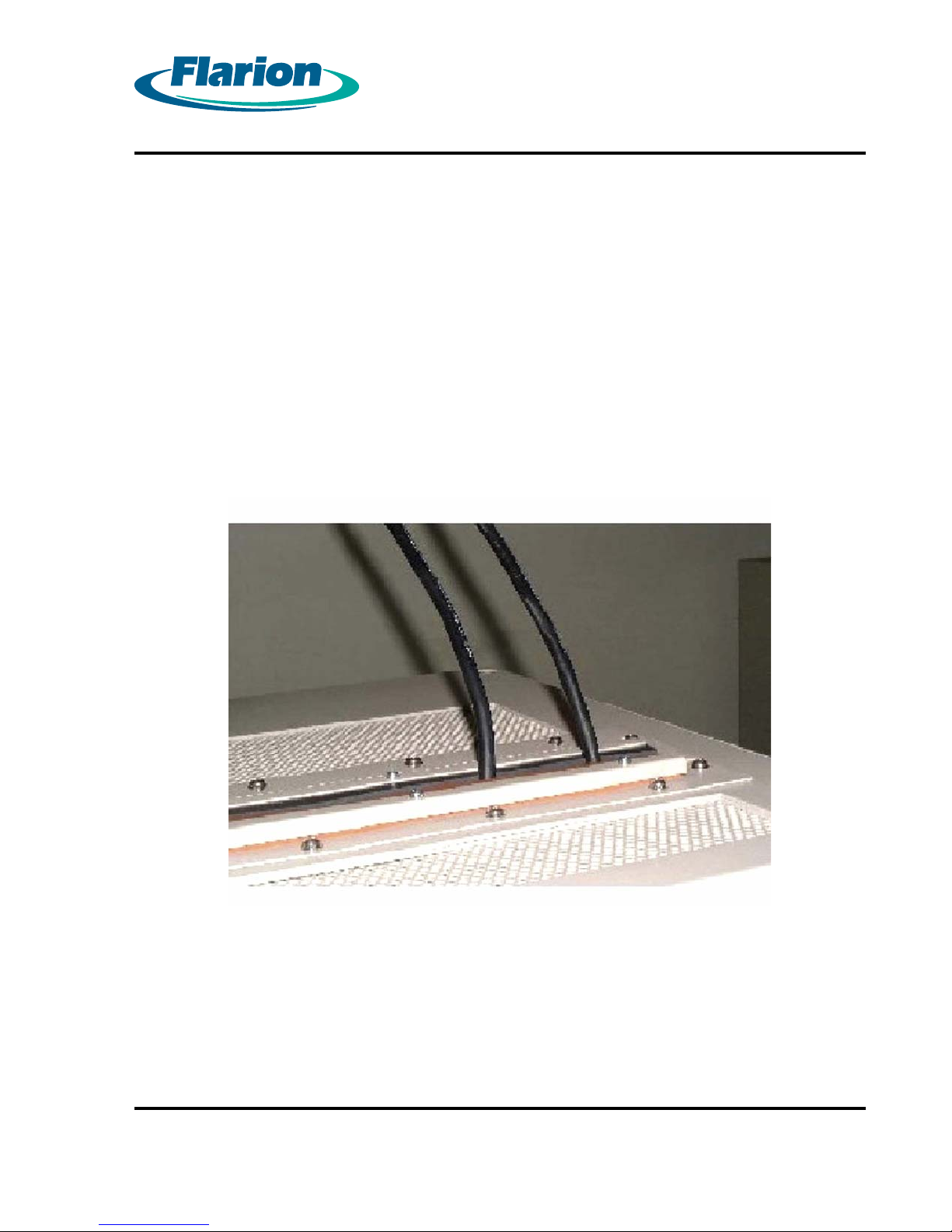
Figure 6.4 Top of Cabinet with Two Antenna Cables Installed shows two antenna cables
installed.
Page 29
Figure 6.4 Top of Cabinet with Two Antenna Cables Installed
RadioRouter®BaseStation Installation Guide — Draft
Version 0.5 - © 2003
Page 29
Page 40

Page 30
Chapter 7. Installing the Alarm Connections
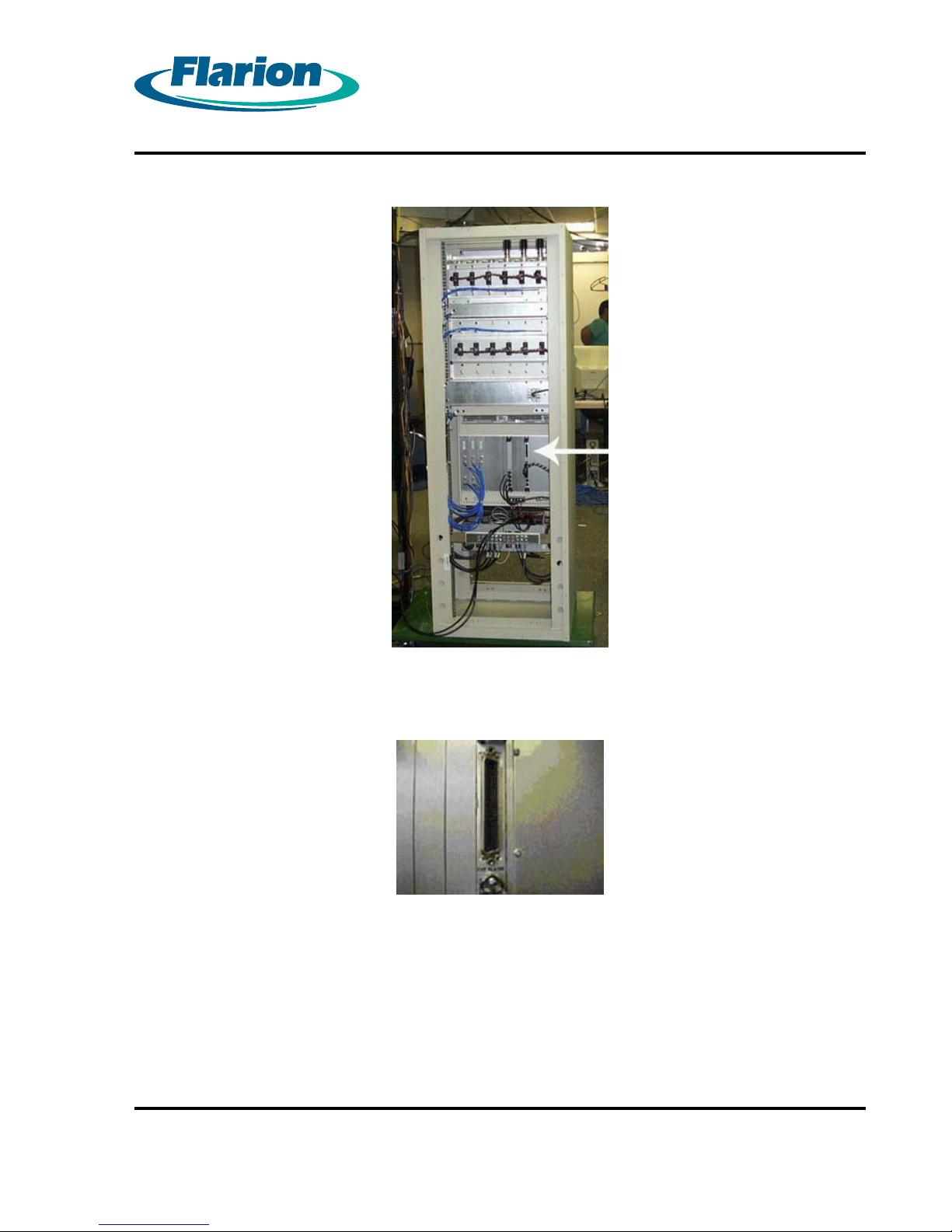
Connection to the system alarm contacts is through a 50–pin AMP connector (part no. 55494–2).
The connector is typically site specific depending on which alarms will be used in a given
installation.
The alarm connector is located in the rear of the cabinet. See Figure 7.1 Cabinet with Alarm
Connection — Rear View and Figure 7.2 Alarm Connector.
Page 30
RadioRouter®BaseStation Installation Guide — Draft
Version 0.5 - © 2003
Page 41
Page 31
Figure 7.1 Cabinet with Alarm Connection — Rear View
Figure 7.2 Alarm Connector
Cables can be routed to the connector using the procedures described in Section 4.1. Routing
the Cables.
RadioRouter®BaseStation Installation Guide — Draft
Version 0.5 - © 2003
Page 31
Page 42
Page 32
Chapter 8. Powering Up the Cabinet
The cabinet requires DC power to operate. Before attempting to power up the cabinet, verify that
DC power is available. It may be necessary to wait for a maintenance window to connect the
cabinet to DC power and perform this procedure.
WARNING:
ALL POWER OPERATIONS SHOULD BE PERFORMED BY QUALIFIED
PERSONNEL ONLY. BEFORE ATTEMPTING TO POWER UP THE
SYSTEM, CONFIRM THAT ALL POWER CONNECTIONS HAVE BEEN
MADE PROPERLY.
CAUTION:
After the RadioRouter BaseStation is powered up, it cannot be
powered down without the use of a craft access terminal. Powering
the BaseStation down witho ut the use of a craft access terminal could
permanently damage the equipment.
Page 32
RadioRouter®BaseStation Installation Guide — Draft
Version 0.5 - © 2003
Page 43
Page 33
Procedure 8-1 Powering Up the Cabinet
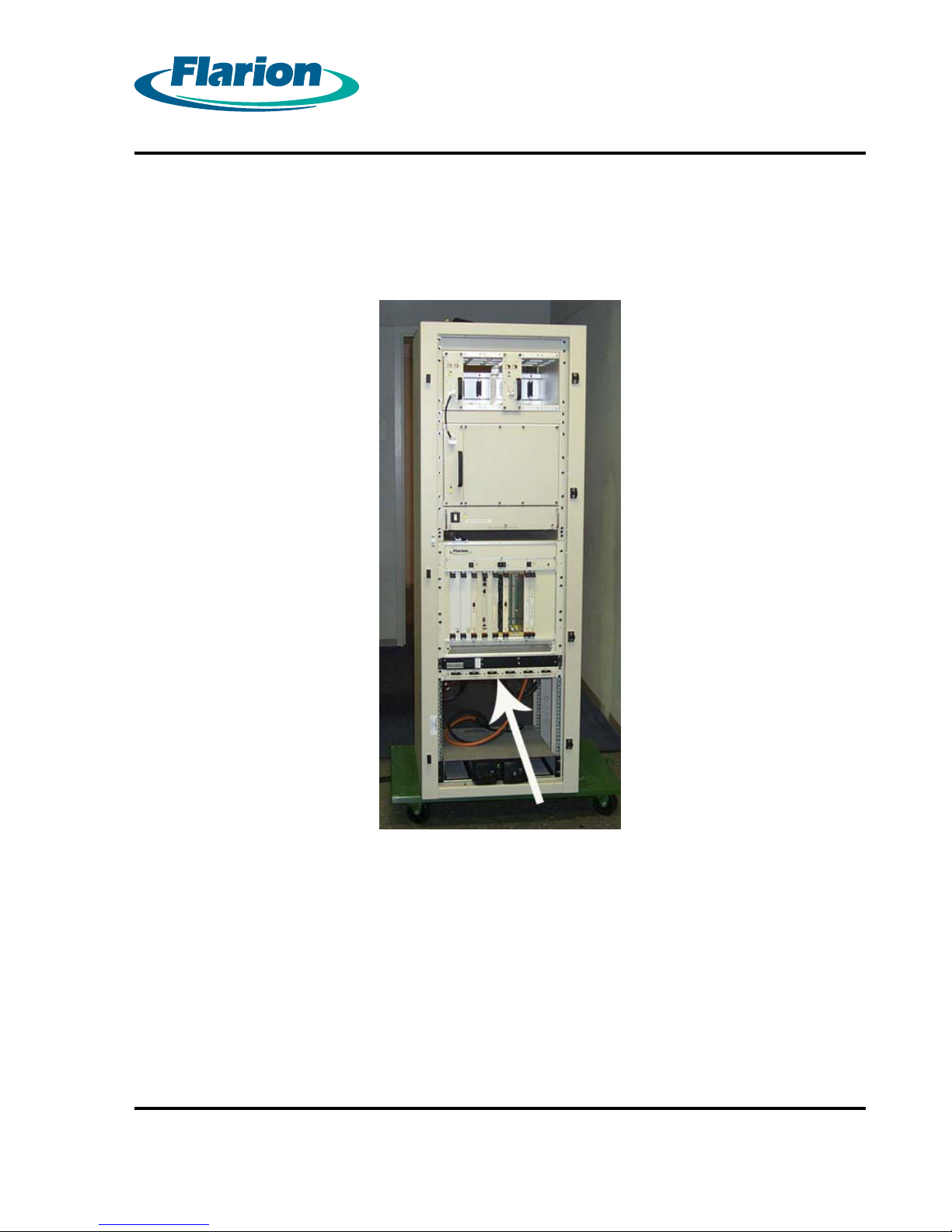
The cabinet is powered up using the circuit breakers o n the distribution panel on the front of the
cabinet. See Figure 8.1 Distribution Panel with Circuit Breakers — Front View
Figure 8.1 Distribution Panel with Circuit Breakers — Front View
RadioRouter®BaseStation Installation Guide — Draft
Version 0.5 - © 2003
Page 33
Page 44
Page 34
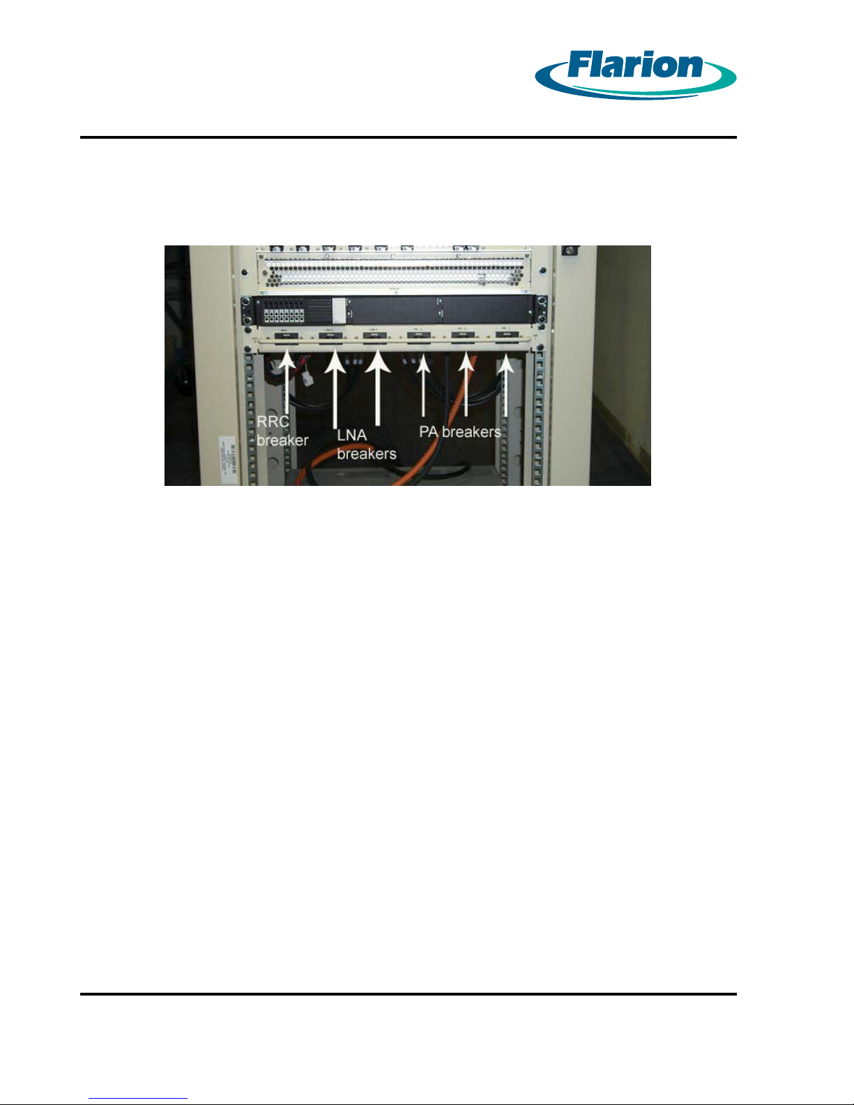
Turn on the RRC breaker. The RRC breaker is on the left as you face the cabinet. See
1.
Figure 8.2 Circuit Breakers — Front View
Figure 8.2 Circuit Breakers — Front View
Turn on the LNA breakers which are located next to the RRC breaker.
2.
Turn on the PA breakers. The PA breakers are on the right of the LNA breakers.
3.
Page 34
RadioRouter®BaseStation Installation Guide — Draft
Version 0.5 - © 2003
Page 45
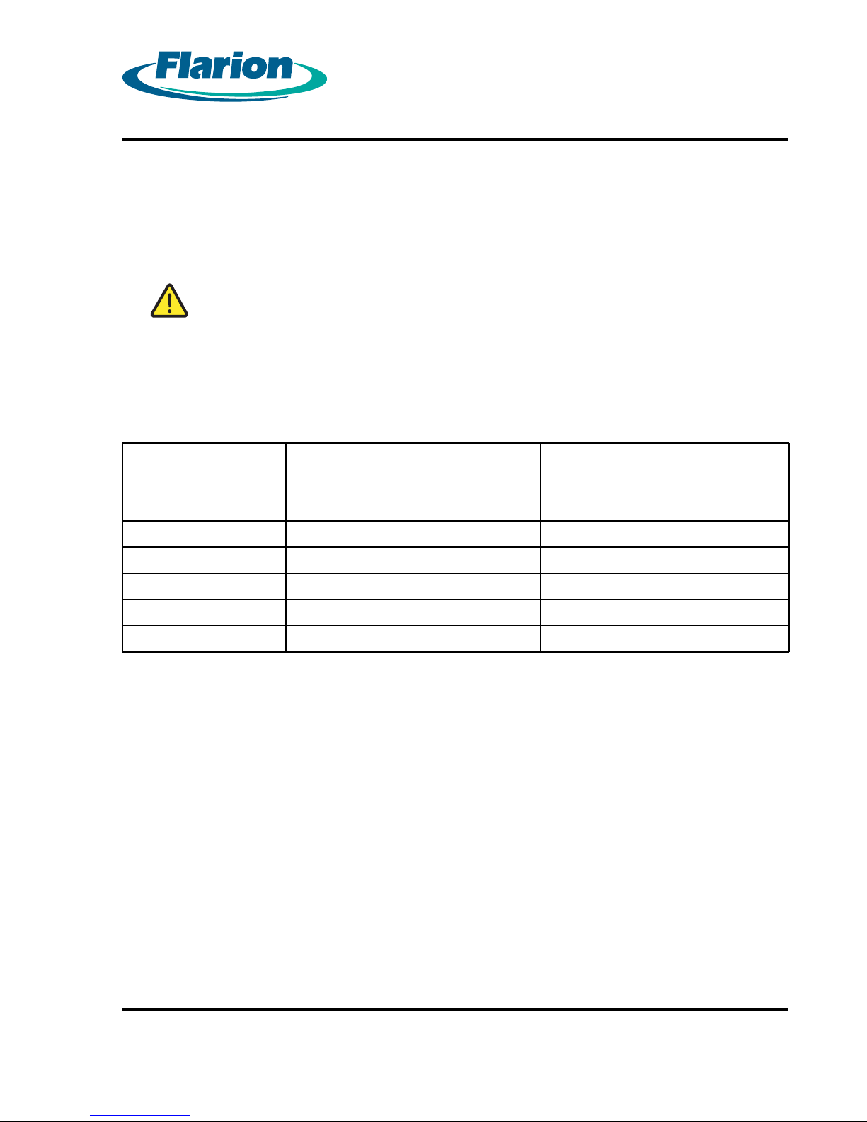
Verify that the LEDs on the front of the cabinet match Table 8.1 Power On Expected LEDs.
4.
If the LEDs do not match the table, power the system down and check the wiring.
WARNING:
AFTER THE RADIOROUTER BASESTATION IS POWERED U P, IT CANNOT
BE POWERED DOWN WITHOUT THE USE OF A CRAFT ACCESS
TERMINAL. POWERING THE BASESTATION DOWN WITHOUT TH E USE
OF A CRAFT ACCESS TERMINAL COULD PERMANENTLY DAMAGE
THE EQUIPMENT.
Table 8.1 Power On Expected LEDs
Page 35
Unit LED Name
PDU Fan Tray FAN Green
RRC FAN STA TUS Green
RRC FAN STA TUS Green
PCU1 ON (GREEN) FAIL (RED) Green
PCU2 ON (GREEN) FAIL (RED) Green
Condition
RadioRouter®BaseStation Installation Guide — Draft
Version 0.5 - © 2003
Page 35
Page 46

Page 36
Chapter 9. Powering Down the Cabinet
The RadioRouter BaseStation is powered down using a PC connected to the COM1 port on
the MCU board. The PC should be running a terminal emulation such as Microsoft Windows
HyperTerminal.
WARNING:
AFTER THE RADIOROUTER BASESTATION IS POWERED UP, IT CANNOT
BE POWERED DOWN WITHOUT THE USE OF A CRAFT ACCESS
TERMINAL. POWERING THE BASESTATION DOWN WITHOUT THE USE
OF A CRAFT ACCESS TERMINAL COULD PERMANENTLY DA MAGE
THE EQUIPMENT.
Procedure 9-1 Powering Down the Cabinet
Connect a PC to the serial port of the MCU.
1.
Run a terminal emulator such as Microsoft Window HyperTerminal.
2.
At the
3.
At the
4.
At the
5.
keys after hitting Enter or the system will restart.
The system will display the message
6.
Press any key to reboot.
Turn off the PA breakers. The PA breakers are on the right as you face the cabinet. See
7.
Figure 8.2 Circuit Breakers — Front View
Turn off the LNA breakers which are located to the left of the PA breakers.
8.
Turn off the RRC breaker. The RRC breaker is on the left as you face the cabinet next to
9.
the LNA breakers.
Login:
Password:
BS_Name#>
prompt, type
prompt, type the root login password and press Enter.
prompt, type
root
and press Enter.
halt
and press Enter. Be careful not to touch any other
System Halted
Do not press any keys.
followed by the message
Page 36
RadioRouter®BaseStation Installation Guide — Draft
Version 0.5 - © 2003
Page 47

Page 37
Chapter 10. Verifying the Installation
Verifying the proper installation of the cabinet is done in two parts:
1. Verifying the physical installation
2. Verifying the BaseStation operation
All items listed must be verified before the installation can be considered complete.
10.1. Verifying the Physical Installation
Verify the following:
1. Clearance requirements are met — at least 24” front and 6” rear. There must be room to
open the cabinet doors for service.
2. The base station is powered up. All the LEDs in Table 8.1 Power On Expected LEDs must
reflect the states listed in the table. The system should remai
is necessary to power down the base station, do so only in accordance with the instructions
in Chapter 9. Powering Down the Cabinet .
3. Correct terminations on all T1 and alarm cables
4. No crimps in RF cables
5. RF cable markings match those specified in Chapter 6. Connecting the Antennas Cables.
ninthepoweredupstate. Ifit
10.2. Verifying the Base Station Operation
Operation of the base station is verified by logging in and confirming communication with the
network. This verifies both the base station operation and the c onnectivity of the T1/Ethernet link.
Procedure 10-1 Communicating with the Core Network
Connect a PC to the serial port of the MCU.
1.
Run a terminal emulator such as Microsoft Window HyperTerminal.
2.
At the
3.
At the
4.
You should see status messages ending in the message
5.
The system is Up at the required run level — 4
The system should respond with the
6.
station is at least minimally operational.
Login:
Password:
prompt, type
prompt, type the install login password and press Enter.
install
and press Enter.
BS_Name#>
prompt. This confirms t
.PressEnter.
hat the base
RadioRouter®BaseStation Installation Guide — Draft
Version 0.5 - © 2003
Page 37
Page 48

Page 38
Ping the default gateway to verify network connectivity.
7.
Page 38
RadioRouter®BaseStation Installation Guide — Draft
Version 0.5 - © 2003
Page 49
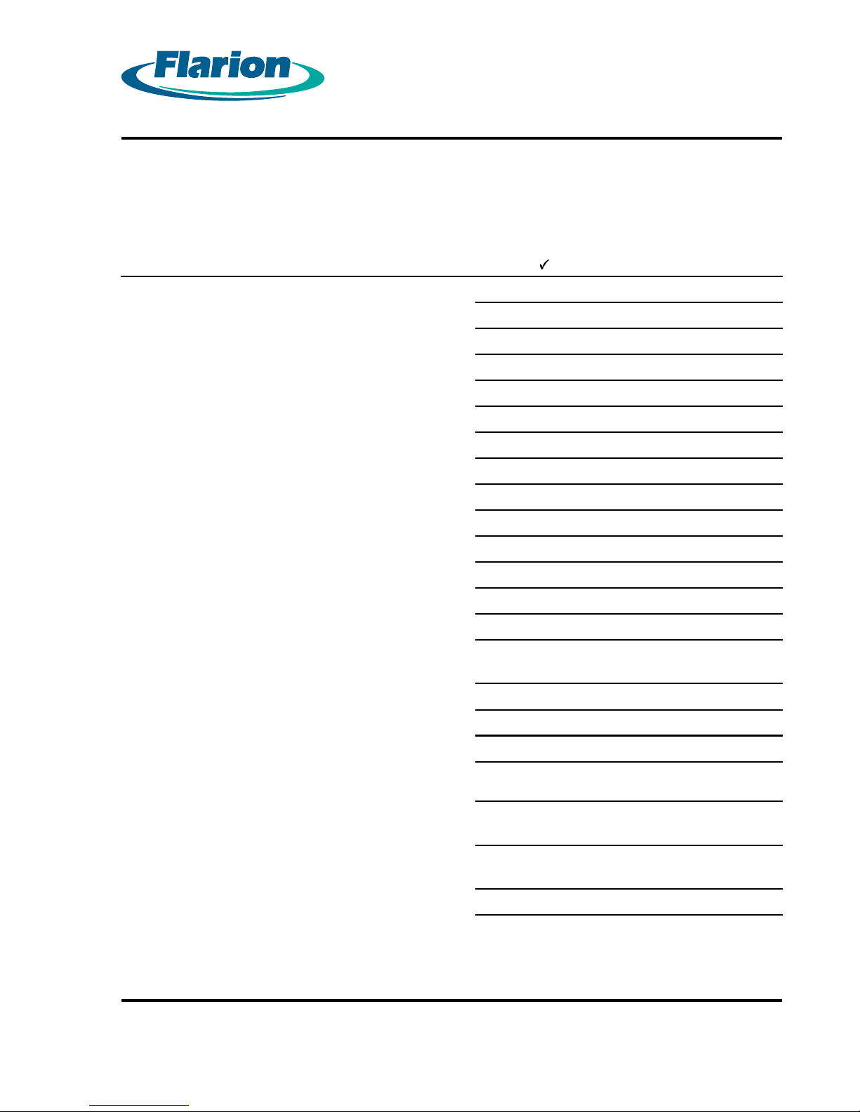
Page A-1
APPENDIX A
RadioRouter BaseStation Site Preparation Punchlist
Site Preparation Items If Okay OR Describe Outage
Environment
Adequate C learance: 24” front 6” rear
Electrical system
Electrical outlets
Master Ground Bar
Other
Antenna plant
Surge arrestor mounting
6 Tx/Rx antenna line surge protectors
T1 connection
T1 surge arrestor
Surge arrestor grounded
Alarm connection
1 AC power failure alar m termination point
1 high temperature power failure alarm
termination point
Cable Support
Trays or other support
Cables
DC power cabling: #6 AWG THHN or THWN
Ground cabling to master ground bar: #6 AWG
THHN or THWN
RF cabling to surge arrestors: 50–ohm
semiflexible rigid
T1 cabling: 2–pair shielded
RadioRouter®BaseStation Installation Guide — Draft
Version 0.5 - © 2003
Page A-1
Page 50

Page A-2
Alarm sensor cables
Page A-2
RadioRouter®BaseStation Installation Guide — Draft
Version 0.5 - © 2003
Page 51
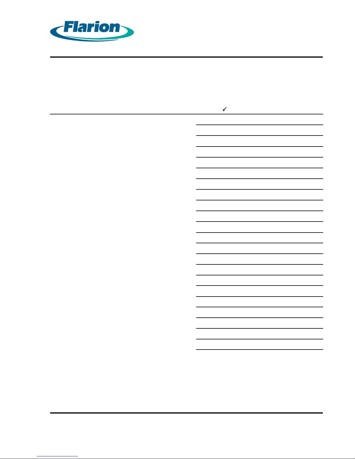
APPENDIX B
RadioRouter BaseStation Installation Punchlist
Page B-1
Installation Items
Overall
Cabinet is physically intact
RadioRouter Chassis
MCU
BHU
PCU
BBU
TXU
RXU
AIU
LNA/Duplexers
Power Subsystem
T1/Ethernet
If Okay
OR Describe Outage
Alarm Connection
Antenna Connections
Other
RadioRouter®BaseStation Installation Guide — Draft
Version 0.5 - © 2003
Page B-1
 Loading...