

Page 1
FF-1
ORIGINAL INSTRUCTIONS
EN
FR
TRADUCTION DES INSTUCTIONS ORIGINALES
DE
ÜBERSETZUNG DER ORIGINALANLEITUNGEN
ES
TRADUCCIÓN DE LAS INSTRUCCIONES ORIGINALES
C-1210 REV A
Page 2
FF-1
EN
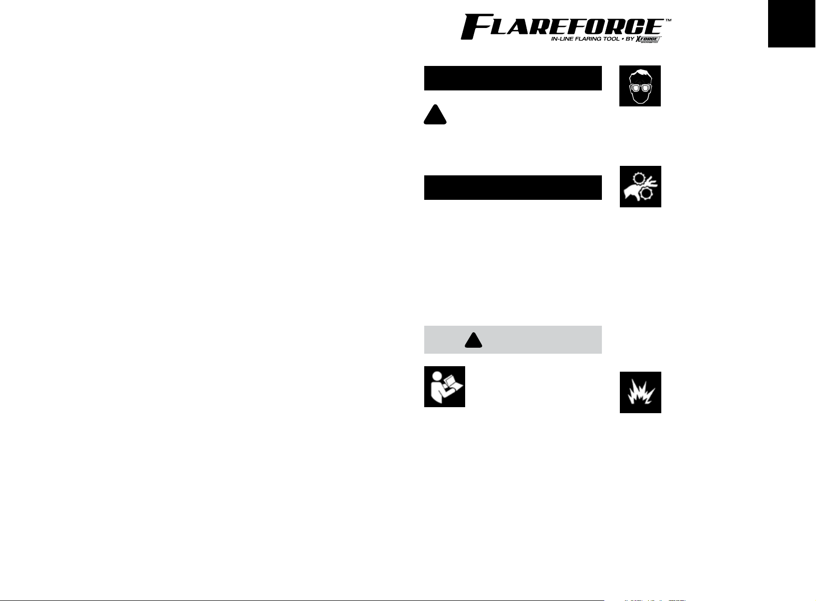
SAFETY INFORMATION
Read these instructions carefully before
!
setting up, operating, or servicing the
FF-1 FlareForce™ tool. Keep these
instructions in a safe, convenient place
for easy reference.
SAFETY MESSAGES
AGS/XForce Tools provides safety messages
covering reasonable situations that could be
encountered while using the FF-1 FlareForce™
tool. However, responsibility remains with the
operator to always be knowledgeable about
the tool, situation, materials and procedures
involved in any repair to ensure the safety of all
in the work environment.
!
WARNING
Flying particles can be
generated while using this tool.
• WEAR SAFETY GOGGLES —
user and bystander.
Flying particles can cause eye injury.
This tool has moving parts and
substantial weight.
• Keep hands and other body parts away
from moving parts.
• Disconnect from air supply before moving.
• Contain hair before use.
• Do not wear loose clothing or jewelry.
• Keep tool clean and free of oil and grease.
• Do not operate under the influence of
alcohol or drugs.
Hands, clothing or body parts can
become entangled causing injury if tool
is used without precaution.
Improper use of FlareForce™
can result in accidents.
• Read and follow all instructions, precautions,
and safety messages.
• Keep instructions available for training
new users.
Bodily injury can result from accidents due to
improper use.
Use of this tool for
reworking lines may expose
user to fire hazards.
• Do not use on gas lines or near other
flammable liquids or vapors.
• Do not lubricate tool with volatile liquids;
use only recommended lubricants.
Ignition of flammable vapors may cause
burns to use.
3
Page 3
FF-1FF-1
ENEN
PRECAUTIONS SAVE THESE
WORK AREA
• Keep a clean and well-lit work area.
• Keep FlareForce™ out of the reach
of children.
AIR SUPPLY
• Use a clean, moisture-free, well-lubricated,
air supply at 90 psig (6.2 bar, 620 kPA)
maximum pressure.
• Always use proper air line connectors and
attach air hoses securely.
• Shut off air supply when not in use.
Disconnect air supply when not used
for long periods of time.
MAINTENANCE
• For long term storage, lubricate and store in a
dry place at a moderate temperature.
• Do not modify the FlareForce™ or make
temporary repairs.
• If tool becomes damaged beyond repair,
return to manufacturer for disposition or
disassemble it and recycle materials.
INSTRUCTIONS
SPECIFICATIONS
Recommended Air Pressure
...........................90 psig (6.2 bar, 620kPA) max
Air Inlet Thread Size..........................1/4" NPT
Air Supply Hose Size.......3/8" (9.5 mm) ID min
Height.....................................10.25" (26.0 cm)
Length......................................9.50" (24.1 cm)
Width..........................................3.50" (8.9 cm)
Weight....................................7.51lbs (3.40 kg)
FLAREFORCE™ FF-1
The FlareForce™ in-line flaring tool is a
revolutionary new way to create tube flares. Its
patented design changes the way professional
mechanics perform fluid transfer repairs,
including brake, fuel, and transmission systems.
No other tube flaring product is as fast, versatile
and easy to use as FlareForce™! Create perfect
tube flares for brake, fuel, and transmission
lines in seconds!
• Creates 3 OE-style flares — single (not for
brake systems), double (or inverted), and
bubble (or ISO) flares.
• Works on steel lines, Poly-Armour
similar coated lines, and NiCopp® nickelcopper lines.
• For use with 3/16", 1/4", 6mm, 5/16", and
3/8" OD tubing.
®
or
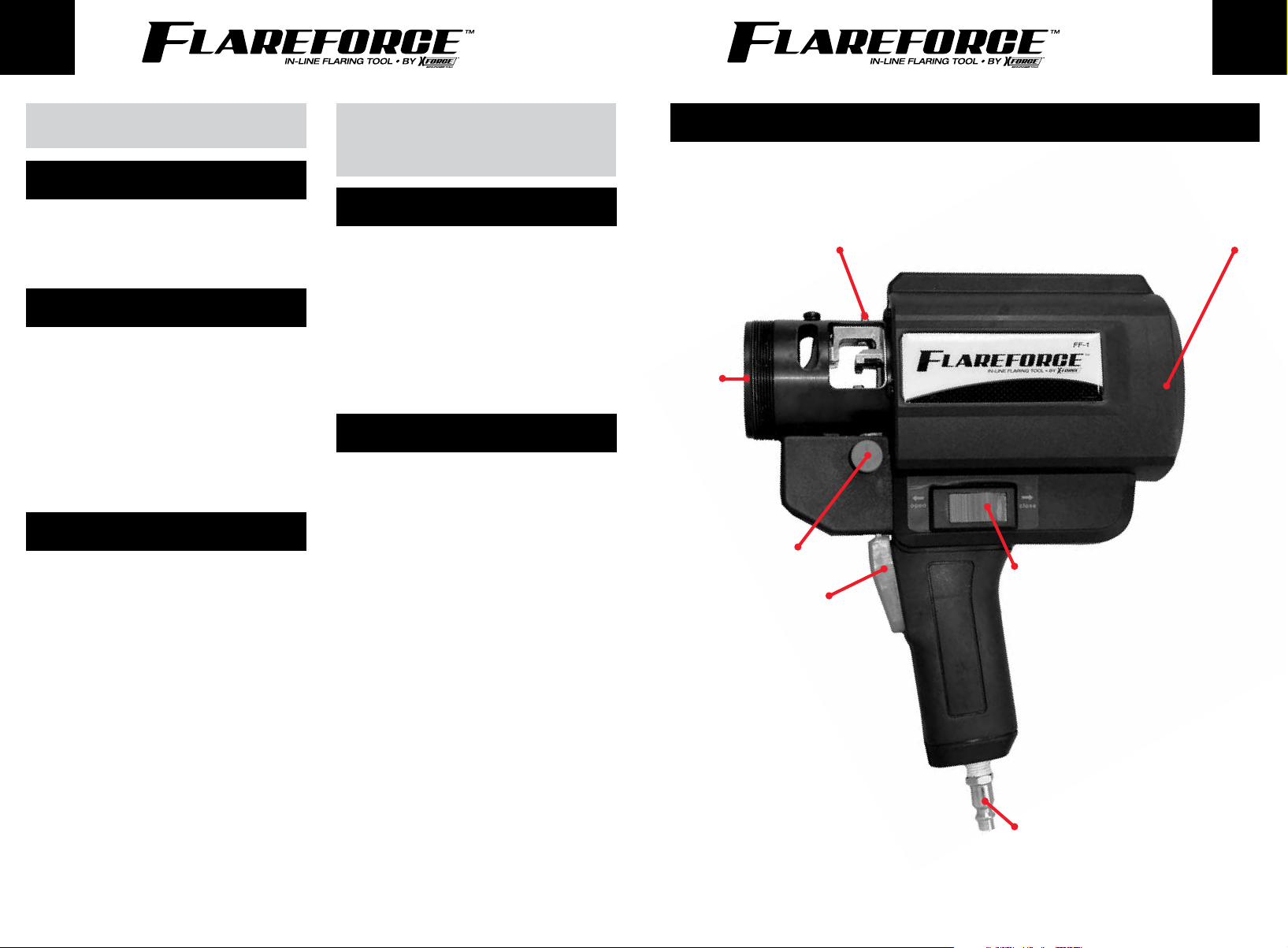
PARTS LISTING
1. Housing/Main Assembly (detailed listing of main assembly is available by request).
DIE SLIDE RETAINER TAB HOUSING/MAIN ASSEMBLY
CHUCK
RESET LEVER
ACTIVATION SWITCH
TRIGGER
AIR HOSE CONNECTOR
44 5
Page 4
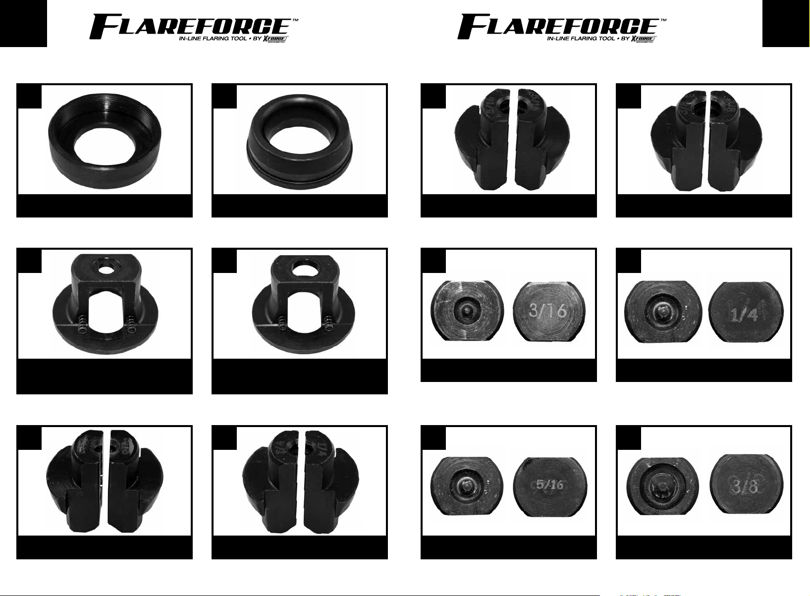
2. Retainer Assembly 4. Jaw Sets
FF-1FF-1
ENEN
2.1 4.3
RETAINER NUT 5/16" JAW SET
3. Jaw Holders 5. Stage 1 Dies
3.1
3/16" JAW HOLDER WITH SPRINGS
2.2 4.4
TAPER RING 3/8" JAW SET
3.2
1/4", 6MM , 5/16", 3/8" JAW HOLDER
WITH SPRINGS
5.1 5.2
FRONT FRONTBACK BACK
3/16" STAGE 1 DIE 1/4" (6MM) STAGE 1 DIE
4. Jaw Sets
4.1
3/16" JAW SET
4.2
1/4" (6MM) JAW SET
66 7
5.3 5.4
FRONT FRONTBACK BACK
5/16" STAGE 1 DIE 3/8" STAGE 1 DIE
Page 5
FF-1FF-1
ENEN
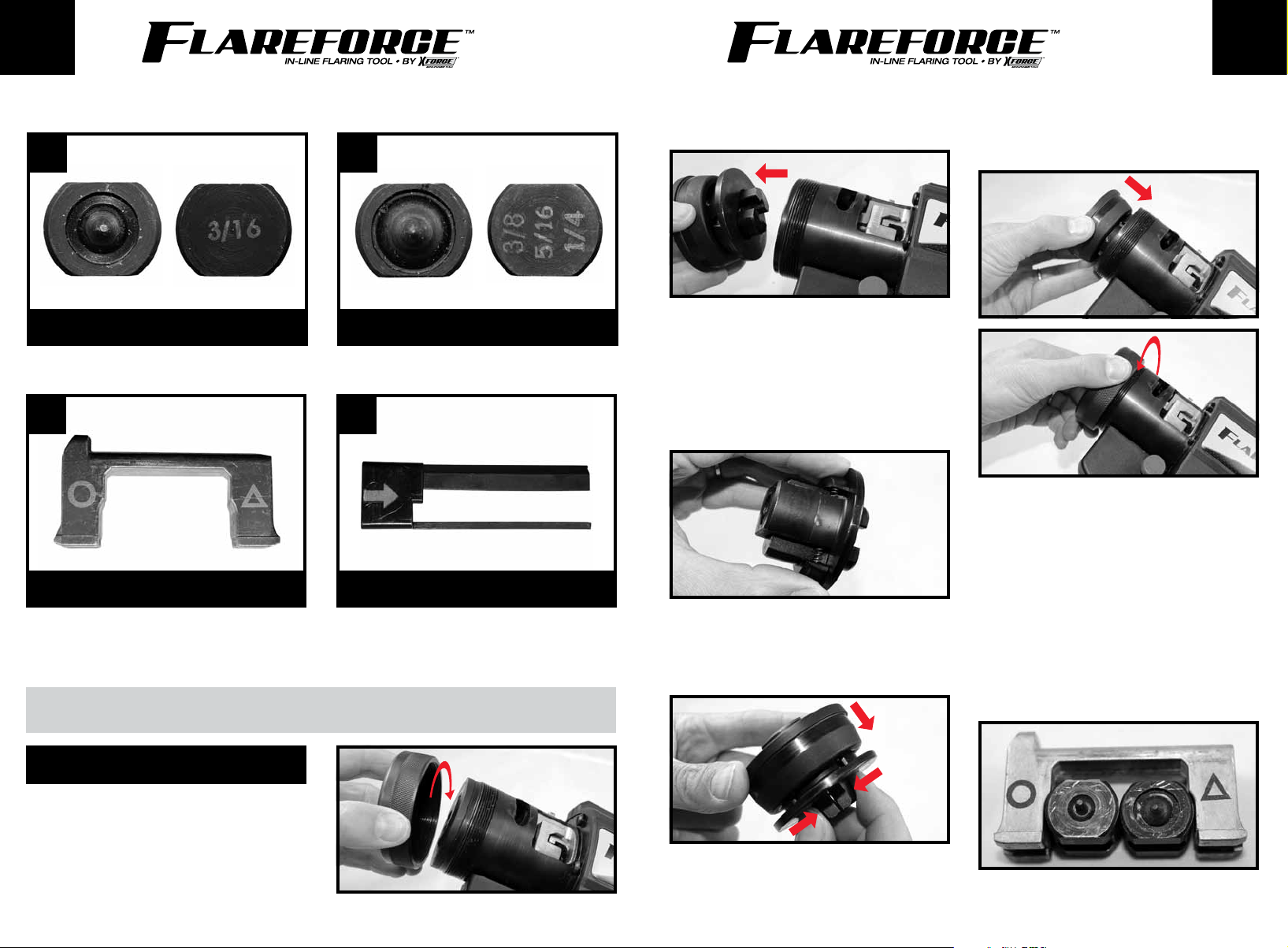
6. Stage 2 Dies
6.1 6.2
FRONTFRONT BACKBACK
3/16" STAGE 2 DIE 1/4", 6MM, 5/16", 3/8" STAGE 2 DIE
7. Die Slide Mechanism
7.1 7.2
DIE SLIDE PLASTIC LOADER
Tool comes assembled wiTh 3/16" jaws and dies.
INSTRUCTIONS
2. Remove (2.2) Taper Ring, (3) Jaw Holder and
(4) Jaw Set from chuck.
3. Place the correct size (4) Jaw Set for the
tubing you are flaring into the correct (3) Jaw
Holder, making sure the springs are properly
positioned *Use (3.1) 3/16"Jaw Holder with
Springs for (4.1) 3/16" Jaw Set, while all
other Jaw Sets will use the (3.2) 1/4", 6mm,
5/16", 3/8" Jaw Holder with Springs.
4. Squeezing rear end of the (4) Jaw Set
together to hold spring tension, place (2.2)
Taper Ring over the (3) Jaw Holder and
(4) Jaw Set.
5. Slide assembly into chuck housing and lock
down by rotating (2.1) Retainer Nut clockwise
until secured tightly in place.
To load The dies:
1. Place the correct Dies (5 & 6) for the
diameter tubing you are flaring into the
(7.1) Die Slide. DIES MUST BE PLACED IN
CORRECT ORDER AND ORIENTATION FOR
PROPER FUNCTION. The (5) Stage 1 Die will
be placed closest to the circular symbol on
the (7.1) Die Slide, while the (6) Stage 2 Die
will be placed closest to the triangular symbol
on the (7.1) Die Slide.
SETUP
To load The chuck:
1. Remove the (2.1) Retainer Nut on front of
chuck by rotating counterclockwise.
88 9
Page 6
FF-1FF-1
ENEN
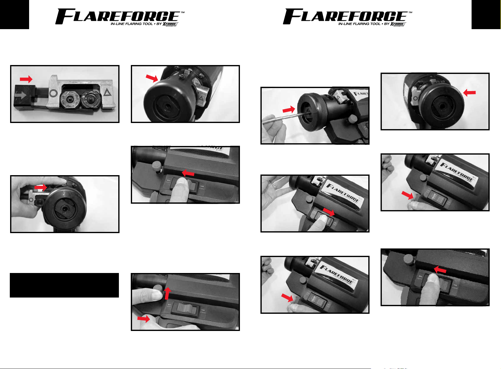
2. Slide the (7.2) Plastic Loader onto the (7.1)
Die Slide so that it just holds both Dies
(5 & 6) in place.
3. Push the Die Slide retainer tab at top of
chuck towards the body of the tool, while
inserting the (7) Die Slide Mechanism into
the chuck from the left to the right. The (7.2)
Plastic Loader will be pushed out as the (7.1)
Die Slide locks into position in the chuck.
These setup instructions apply to all tube
sizes. Be sure to select the proper sizes for
the entire assembly or damage to the tubing
and/or the tool will occur.
left side of tool as shown with triangular
symbol visible before flaring process is
started.
3. Position slide by placing activation switch in
the open position.
4. Set the tubing stop by depressing trigger
and (while trigger is still being depressed)
pushing up on the reset lever. You should hear
air pressure released and the mechanical
sound of the ram being positioned. While
still holding the reset lever in the up position,
release the trigger. The reset lever will remain
in the up position after releasing trigger.
5. Guide the end of the tubing to be flared into
the chuck until you feel it seated over the
pin on the (5) Stage 1 Die and it hits the
stop. The end of the line must be fully seated
and bottomed-out against the die for proper
flaring.
6. With end of the line seated against the (5)
Stage 1 Die and centered in the chuck, place
activation switch in the close position.
7. Hold down trigger for 2-3 seconds to perform
first part of the flaring operation.
9. Release trigger and push (7.1) Die Slide from
left side all the way to right position. Slide
should protrude from right side of tool with
the circular symbol now showing.
10. Hold down trigger for 2-3 seconds to
perform second part of flaring operation.
11. Place activation switch in the open position
and carefully remove line from chuck. You
should now have a completed, double
(inverted) or SAE 45 degree flared tube end.
FLARING A BUBBLE/ISO FLARE OR
AN INVERTED/DOUBLE FLARE
1. Attach air hose to connector at bottom of tool
handle.
2. Make sure (7.1) Die Slide is in place by
pushing from right side all the way to left
position. (7.1) Die Slide should protrude from
8. At this point you have created a bubble or
ISO flare. If this is the flare you required,
you may skip to step 11. To create an
inverted flare, proceed to step 9.
1010 11
Page 7
FF-1FF-1
ENEN
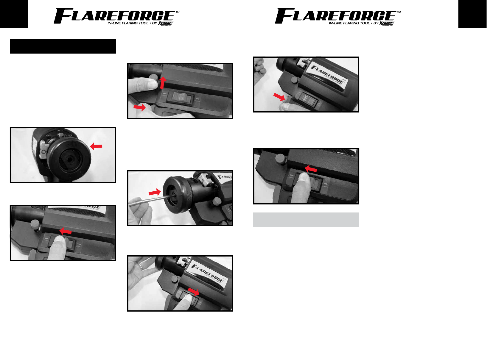
CREATING A SINGLE FLARE
1. Attach air hose to connector at bottom of tool
handle.
2. Make sure (7.1) Die Slide is in place by
pushing from left side all the way to right
position. (7.1) Die Slide should protrude
from right side of tool as shown with circular
symbol visible before flaring process is
started.
3. Position slide by placing activation switch in
the open position.
4. Set the tubing stop by depressing trigger
and (while trigger is still being depressed)
pushing up on the reset lever. You should hear
air pressure released and the mechanical
sound of the ram being positioned. While
still holding the reset lever in the up position,
release the trigger. The reset lever will remain
in the up position after releasing trigger.
5. Guide the end of the tubing to be flared into
the chuck until you feel it seated over the
cone on the (6) Stage 2 Die and it hits the
stop. The end of the line must be fully seated
and bottomed out against the die for proper
flaring.
6. With end of the line seated against the (6)
Stage 2 Die and centered in the chuck, place
activation switch in the close position.
7. Hold down trigger for 2-3 seconds to perform
the flaring operation.
8. Place activation switch in the open position
and carefully remove line from chuck. You
should now have a completed, single-flared
tube end.
WARRANTY
AGS® warrants to Customers who purchase
Product from authorized AGS® distribution
channels for use in their profession that AGS®
brand Products and XForce® brand Products
will be free from defects in workmanship
and materials. The warranty duration is one
year from the time of purchase. Consumable
Products are warranted, at the time of sale, only
against defects in workmanship or materials
that prevent their use. Consumable products
are goods reasonably expected to be used up
or damaged during use. This warranty only
extends to the original Customer and cannot be
transferred or assigned.
During the applicable duration of the warranty,
at its option, AGS® will repair or replace its
Products which fail to give satisfactory service
due to defective workmanship or materials,
or provide a refund by repaying or crediting
Customer with an amount equal to the purchase
price of such Products. Repair, replacement
or refund shall be at the election and expense
of AGS®, and is Customer’s exclusive remedy
in place of all other rights and remedies. Any
products or parts replaced or for which AGS®
has provided a refund are the property of
AGS® and will not be returned. By repairing
or replacing a Product, or providing a refund,
AGS® does not waive a claim that a Product
nevertheless has been subject to abnormal use.
To obtain warranty service, return Products to
an authorized AGS® distributor.
For Customers not serviced by an authorized
AGS® distributor, contact AGS® Customer
Service via telephone at 1-800-253-0403 or
e-mail [email protected].
The following information will be required
with the Customer’s warranty request: (1) date
and proof of purchase, (2) where Customer
purchased the Product, (3) full name, (4)
shipping address, (5) phone number, (6) e-mail
address, (7) item number(s) or approximate
weight of return package. Warranty requests
that do not include all of the required
information will not be processed. Once the
warranty request is validated, the Customer will
be provided an RGA number and sent a shipping
label either electronically thru e-mail or thru
the U.S. mail, and must ship the Product to
AGS®. Upon receipt of the Product, the warranty
claim will be reviewed and the Product will be
inspected. If the warranty request is found to be
valid, the Product will be repaired and returned
to the Customer or a replacement Product
1212 13
Page 8

EN
FF-1
or refund will be shipped to the Customer.
If the warranty claim is found to be invalid,
the original Product will be returned to the
Customer. By repairing or replacing a Product,
or providing a refund, AGS® does not waive a
claim that a Product nevertheless has been
subject to abnormal use.
If you choose not to (1) use a carrier that offers
tracking or (2) insure or declare the full value
of the Product, you will be responsible for any
loss or damage to the Product during shipping.
Replacement or refund will not be issued unless
a valid proof of delivery can be provided.
In addition to any limitations outlined in
warranty statements provided with the Product,
AGS® does NOT provide any warranty for (1)
Products labeled other than AGS® or XForce®
or (2) Products subjected to “abnormal
use”. Products that are not labeled AGS® or
XForce® are subject to the warranty provided
by the manufacturers of those Products and
AGS® will pass along any such warranties.
“Abnormal use” includes misuse, accident,
modification, unreasonable use, abuse, neglect,
lack of maintenance, use in product-related
service, or use after the Product is significantly
worn. Abnormal use also includes, without
limitation, situations when a unit is pulled
using a mechanical vehicle, rolled over large
drops, used in a highly corrosive environment,
modified with non-AGS® or XForce® parts,
overloaded or modified in any way.
THE FOREGOING WARRANTY IS IN LIEU OF
AND EXCLUDES ALL OTHER WARRANTIES
NOT EXPRESSLY SET FORTH HEREIN,
WHETHER EXPRESS OR IMPLIED, BY
OPERATION OF LAW OR OTHERWISE,
INCLUDING BUT NOT LIMITED TO ANY
IMPLIED WARRANTIES OF MERCHANTABILITY
OR FITNESS FOR A PARTICULAR PURPOSE.
Descriptions of Product contained in this
website are for the sole purpose of identifying
Product and shall not be construed as an
express warranty.
1414
Page 9

 Loading...