

Page 1
Page 2

Index
NOTE:
Before beginning you must first measure the width of your
front end from LEFT outer tie rod end zerk (grease) fitting to the
RIGHT outer tie rod end zerk fitting to determine the overall width of
your front end. Write dimension here for further reference
Installation hardware and inventory
PG 2
Section 1 Original System Removal
A. Steering Box & Linkage Removal PG 3
Section 2 Installation of The Flaming River Rack & Cradle
A. Installation of Rack and Cradle PG 4
Section 3 Universal Joint Installation
A. Universal Joint and Steering Shaft Installation PG 5-6
Torque Specs PG 6
Template PG 7
IMPORTANT!!
For safety, before starting, disconnect both battery
cables and ensure the vehicle is properly supported by jack stands.
We recommend that you always install new outer tie rod ends when installing
this kit.
We highly recommend
settings
.
a professional alignment to set the proper alignment
Warranty Disclaimer
Because of their intended usage, the manufacturer makes no warranties whatsoever expressed
or implied, oral or written, to purchasers of their products regarding performance, safety, fit,
merchantability or length of service. Purchasers are responsible for selection of proper goods and
must rely on their own skill or judgment that such goods are suitable for the purchaser’s
application.
- 1 –
11/28/2005
Page 3

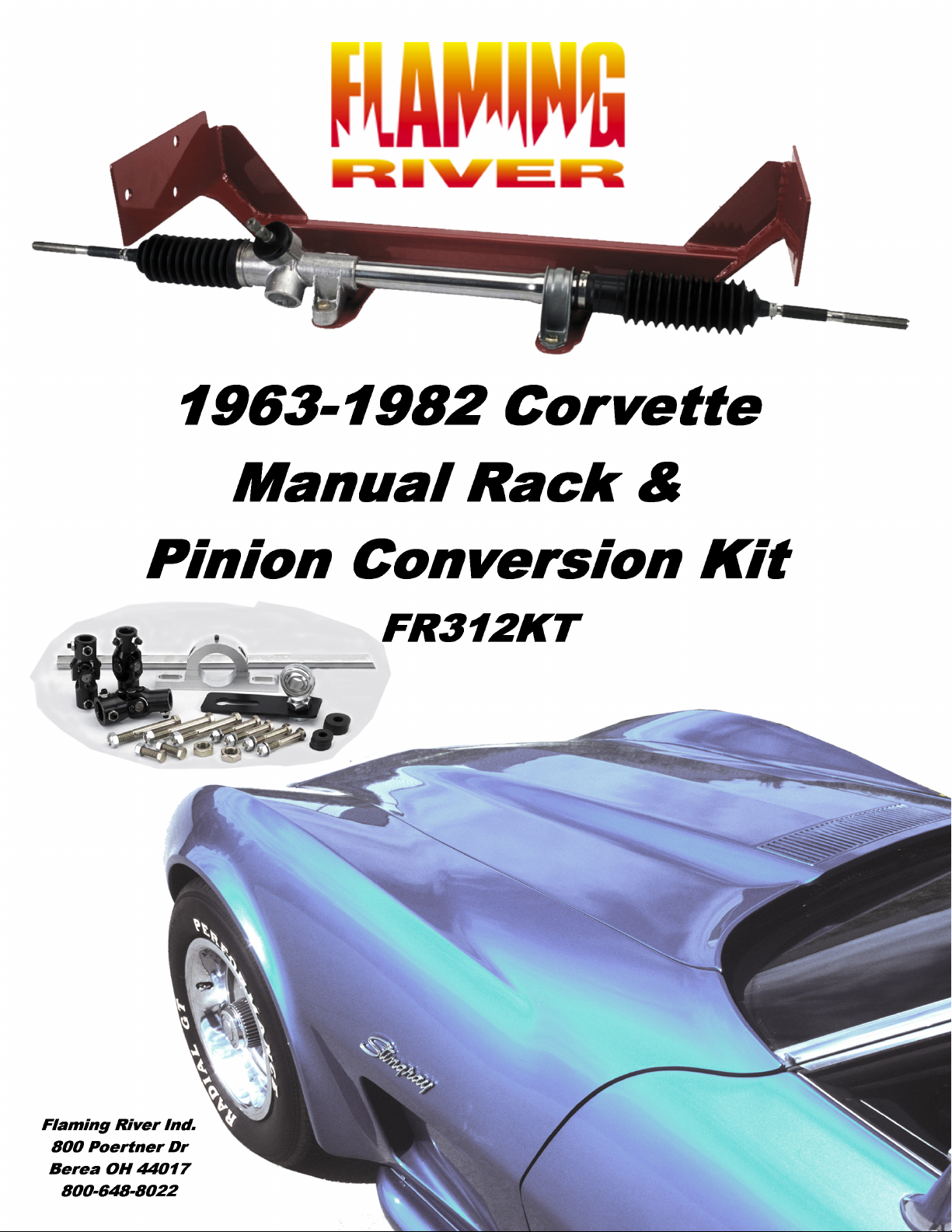
Installation Hardware and Inventory
Part Number Description
Qty
1 BK10300
Vette Support Bearing
Bracket
Bolt 3/8-
3/8-16 Grade 8 Bolt 1.25"
3
16x1.25
Long
3/8-16 Grade 8 Bolt 1.5"
2 Bolt 3/8-16x1.5
Long
Cbolt 3/8-
3/8-16 Carriage Bolt 4.5"
6
16x4.5
Long
1 FR1.75 Saw 1 3/4" Hole Saw
1 FR1507-3Q-8 Corvette Manual Rack
Omni Style Clamp with
1 FR1507C
Bushing
1 FR1709DD
9/16-26 x 3/4" DD U-joint
(Rack)
1 FR1712DD 1"-48 x 3/4"DD U-joint (Column)
1 FR1716DD
3/4"DD x 3/4"DD U-joint
(Center)
1 FR1810 Support Bearing
1 FR1850 18" DD Shaft
1 FRVTM1 Vette Cradle
11 Nut 3/8-16 Lock Nut 3/8-16
2 Nut 5/8-18 Jam nut 5/18-18 Grade 8
16 Wash 3/8 3/8 Flat Washer
- 2 –
11/28/2005
Page 4

Steering Box and Linkage Removal
1) Remove the pinch bolt that retains the rag joint (B-2) to the
steering box.
2) Remove the pitman arm from the steering box (C) using a
pitman arm puller.
3) Remove the two bolts that retain the idler arm to the frame rail.
4) Remove the cotter pins and castle nuts and separate the outer
tie rod ends from the spindles.
5) Next remove the steering linkage (D) from the car.
6) If you have power steering remove the lines from your power
box, pump and pump brackets. A shorter belt may need to be
installed.
7) Remove the three bolts that retain the box to the frame rail and
remove the box from the car.
- 3 –
11/28/2005
Page 5

Installation of Flaming River Rack & Pinion
1) Begin by centering the rack. Turn the rack all the too the left.
Next turn it all the way too the right counting the number of
turns. Then go back to the left half the number of turns.
2) Install the passenger side rack mounting clamp onto rack tube.
3) Place rack onto cradle mounting feet
4) Using the 1 ½”x 3/8 bolts on the driver’s side and 1”x 3/8 bolts
on the passenger side mount the rack to the cradle.
5) Install the rack and pinion mounting cradle by placing it in
between the frame rails and lining up the mounting holes. On
the driver’s side use the original steering box mounting holes
and on the passenger side the idler arm mounting holes.
6) Slide the new carriage bolts through the holes and tighten to
45-50 ft lbs.
7) Install the outer tie rod ends and jam nuts onto the outer tie rod
end assembly and install them into the inner tie rod ends.
Adjust the outer ends to the dimension that you checked on the
index page.
8) Install the outer tie rod ends into the spindle arms.
- 4 –
11/28/2005
Page 6

Universal Joint System
1) Remove the template on the last page.
2) Cut out template
motor mount bolt.
3) Place cut out template on the engine support bracket aligning the
motor mount bolt hole on the motor mount bolt. Template should
be facing the firewall.
4) Center punch the “X” in the large hole on the template and then
cut out the hole using the hole saw in the kit.
5) Install support-bearing mount onto a cradle mounting bolt. Note:
The angle of this mount is set for most applications. Some
adjustment may be necessary for the correct angle and u-joint
alignment.
along the solid line and cut out hole for the
6) We recommend the use of ¾” dowel rod to mock up the steering
shaft to obtain the correct length before you cut the steel DD shaft.
7) Install your shaft kit and snug each set screw so that it will leave a
mark in the shafts.
- 5 –
11/28/2005
Page 7

Universal Joint System Con’t
8) Remove shaft and dimple each setscrew mark using a ¼” drill bit.
(As shown below.)
9) Re-install the shafts using high strength (red) thread locker on
the set screw threads. Tighten each setscrew to 25 ft.-lbs. tighten
all lock nuts securely. We recommend that you Inspect setscrews
periodically for tightness.
Torque Specs
Cradle to Frame Mounting Bolts 45-50 ft lbs
Outer Tie Rod Ends to Spindle 30-40 ft lbs
Universal Joint Set Screws 25 ft-lbs
- 6 –
11/28/2005
Page 8

Template
- 7 –
11/28/2005
 Loading...