

Page 1
800 Poertner Drive
800
80
Berea, OH 44017
1-
-648-
22
Kit Includes:
NEW FR1497-series steering box (Long shaft) for 1964-1/2-66 Mustang, 1960-66 Ford Falcon,
Ranchero, Mercury Comet
WARRANTY: ONE (1) YEAR FROM DATE OF PURCHASE. REPLACEMENT OF PRODUCT DEEMED
DEFECTIVE BY THE FACTORY.
Tools Required:
Pitman arm puller, steering wheel puller, 3/8” drive socket set, Open/Closed box wrench set,
STEERING BOX INSTALLATION INSTRUCTIONS – 1964-1/2-1966 Mustang, 1960-66 Ford Falcon & Ranchero
torque wrench, red threadlocker, floor jack, 4 jack stands, straight blade screwdriver, Phillips
FR1497-series Long Shaft (including special order units)
head screwdriver (Optional: 3/8” drill, grinding wheel or flat file)
NEEDED PARTS (not supplied): None
IMPORTANT: Make certain the wheels are straight ahead b efore beginning and the vehicle is
properly supported on jack stands. With the wheels straight, mark the top center of the steering
wheel with a piece of tape around the grip to assure the wheel is centered.
NOTE: All boxes are pre-lubricated and pre-adjusted to factory specifications.
Removal of Steering Column
The first part of replacement of the steering box is the removal of the steering column. To remove
the column, follow these steps.
1) Disconnect the ground (–) terminal from the battery.
TECHNICAL BULLETIN # 1011
ANY LABOR INCURRED IS SPECIFICALLY EXCLUDED.
2)
Remove horn button by pushing down on horn hub and turning counter clockwise.
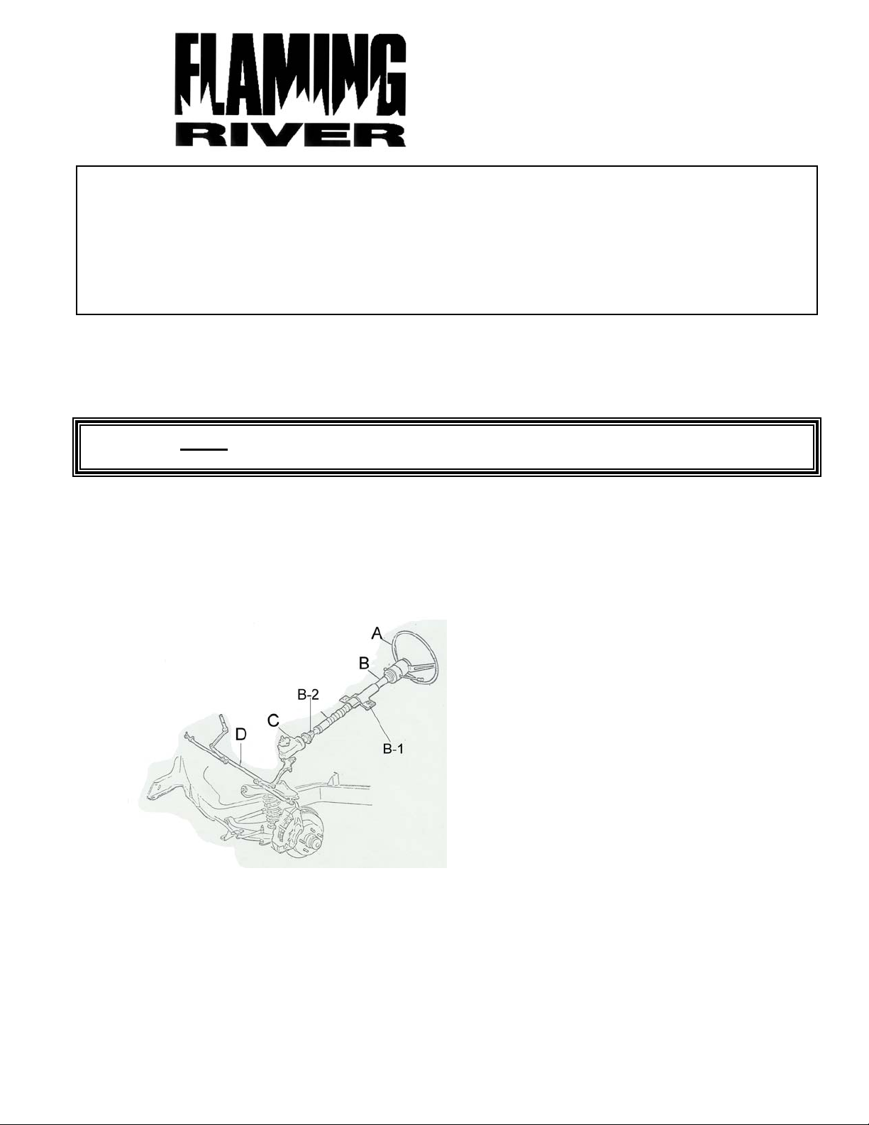
3) Remove steering wheel retaining nut and remove steering wheel (A) by using a steerin g wheel puller.
4) Disconnect the electrical plug towards the base of the column (B).
5) Before removing the column, see PAGE 3. Fill out wiring color verification form before
proceeding.
6) Remove the column support bracket under the dash. There are two nuts one on each side of the
column. (B-1)
7) Remove the upper bushing located at the center of the turn signal switch.
Page 2

8) Remove the column tube by sliding it up off the steering box shaft.
Removal of Steering Box
NOTE: The next steps are performed under the vehicle. For safety, the vehicle must be properly
supported with 4 jack stands.
1) Remove the bolt securing the steering drag link to the pitman arm. (SAVE THE BOLT, NUT,
WASHER; DISCARD COTTER PIN)
2) Remove the pitman arm retaining nut.
3) Using the pitman puller remove the pitman arm.
4) Remove the three bolts that hold the box to the frame rail. (SAVE MOUNTING BOLTS)
5) Remove the box from the vehicle.
Mounting the steering box
IMPORTANT! Center the steering box before installation. Refer to Flaming River Instruction
Bulletin #1012 (enclosed) and follow the procedures to center the steering box’s sector (outp ut)
shaft.
1) Slide long shaft upward through the opening in the firewall.
2) Install the steering box to the frame. Using the torque wrench, tighten the mounting bolts to
50-65 ft-lb.
3) Attach the pitman arm to the steering box. Using the torque wrench, tighten the sector shaft
bolt to 115 ft-lb.
4) Reattach the center link to the pitman arm. Install washer and nut. Tighten nut to 40-45 ft-lb,
install new cotter pin, and bend over ends.
NOTE: For 1960-66 Ford Falcons/Rancheros and Mercury Comets equipped wi th an automatic
column shifter, some grinding or filing is required on the coupler to clear the shifting mechanism
at the base of the steering column. Carefully remove only enough material until the column will
slide over the coupler.
Reinstall the steering column
1) Reinstall the floor mount bracket using the four mounting screws. Be certain to reinstall the
original seals that were removed.
2) Slide the column over the shaft extending upward from the steering box and continue
downward through the floor mount.
3) Insert the alignment bushing into the turn signal switch assembly
4) Fasten floor mount to column and tighten clamp.
5) Reattach turn signal/horn wiring to column.
6) Insert spring over steering shaft
7) Reinstall steering wheel with the tape at the 12 o’clock position and tighten retaining nut to
45-50 ft-lb of torque.
8) Connect horn contact wire to contact on wheel.
9) Reinstall horn button by pushing down and turning clockwise (right).
10) Reconnect the battery terminal
NOTE: Front-end alignment by a service professional following installation is advised.
NOTE: Flaming River recommends periodic inspection of all u-joint setscrews for tightness.
Because of their intended usage, the manufacturer makes no warranties whatsoever expressed or implied, oral or written,
to purchasers of their products regarding performance, safety, fit, merchantability, or length of service. Purchasers are
responsible for selection of proper goods and must rely on their own skill or judgment that such goods are suitable for the
purchaser’s application.
Warranty Disclaimer
021805
 Loading...